
Optimal Design of the Rotor Structure of a HSPMSM Based on Analytic Calculation of Eddy Current Losses

State Key Laboratory of Electrical Insulation and Power Equipment, School of Electrical Engineering, Xi’an Jiaotong University, Xi’an 710049, China
*
Author to whom correspondence should be addressed.
Energies 2017, 10(4), 551; https://doi.org/10.3390/en10040551
Submission received: 12 January 2017
/
Revised: 2 April 2017
/
Accepted: 11 April 2017
/
Published: 17 April 2017
Abstract
:The rotor eddy current losses of a high-speed permanent magnet synchronous motor reduce the efficiency of the motor and increase the temperature rise of the rotor. In severe cases, the permanent magnet of the rotor can be demagnetized, affecting the safe operation of the motor. In this paper, an analytical model of rotor eddy current losses calculation based on Maxwell equations is introduced. The eddy current losses of rotor structures, e.g., protection sleeve, shield layer and permanent magnets, are analyzed. The calculation results of rotor eddy current losses are compared with two-dimensional (2D) finite element analysis. The comparison verifies the accuracy and versatility of analytical calculation. Finally, the influences of the variables on eddy current losses in the derived model are analyzed. Based on the principle of minimizing eddy current losses, an optimized structure with copper layers covering both inner and outer surfaces of the protective sleeve is proposed. Furthermore, the optimized distribution parameter of copper film thickness is obtained.
1. Introduction
Due to the high-power density and excellent transmission efficiency, high-speed permanent magnet synchronous motors (HSPMSM) are widely used in aviation power supply, flywheel energy storage, large-scale high-speed machining, etc. [1,2,3,4,5,6,7]. Compared with traditional motors, the losses per volume and the working temperature rise of HSPMSMs are significantly increased. Especially, the rotor losses caused by the high-frequency magnetic field aggravate the rotor temperature rise [8,9,10,11,12]. Because permanent magnets (PM) in the rotor of the high-speed motor have a non-negligible conductivity, eddy current losses are generated in the high-frequency harmonic magnetic field, leading to more severe temperature rise. The PM demagnetization caused by the rotor temperature rise seriously threatens the safety and reliability of the high-speed motor. It is necessary to precisely calculate the eddy current losses and optimally design the rotor structure in order to reduce the rotor eddy current losses and temperature [13,14,15].
The rotor eddy current losses of PMSM are widely studied in the literature, which can be divided into two categories. Some studies have focused on establishing the approximate calculation model of the rotor eddy current losses. Other researchers have studied the effective measures of reducing rotor eddy current losses. The special rotor structure of HSPMSM makes the rotor eddy current losses analysis and rotor structure optimization more important. An analytic model of the PMs established for analyzing the eddy current losses in PMs of PMSMs was researched in [16,17,18]. Not only was the analytic model of the eddy current losses built, but also the influence of the axial segmentation on eddy current losses was considered in [19]. The rotor losses of the traditional PMSMs have been studied by experts and researchers and the calculation results has been verified in [20,21,22]. In [23,24,25], the influences on different rotor sleeves on the rotor eddy current losses were considered. M. Etemadrezaei, an Iranian scholar, has researched the influences of the copper layer added between the sleeves and the PMs on the rotor eddy current losses. Other methods for reducing losses such as the axial segmentation and circumferential segmentation were widely used in [26,27]. Because of the special rotor structure of HSPMSMs, it is extremely significant to analyze the rotor eddy current losses and optimize the rotor structure.
The traditional calculation and analysis methods of the electromagnetic field in the motor mainly include the analytic method and the numerical calculation method. The rotor eddy current losses can be calculated by the time-step finite element analysis (FEA) method [28,29]. However, the pre-processing, including geometric modeling, meshing and boundary condition setting, requires a long time and large storage memory, unsuitable for industrial applications. The analytic calculation method based on traditional partial differential equation solution without meshing requires only a short time and shows the relationships among variables obviously, which can be easily applied to the motors with the same structure. The rotor eddy current losses can be easily estimated by this method in order to provide the basis for the optimization design [30,31,32].
2. Analytic Calculation of Rotor Eddy Current Losses
2.1. Analytic Calculation Model
The high speed of HSPMSMs, ranging from tens of thousands of revolutions per minute to hundreds of thousands of revolutions per minute, results in large centrifugal force, requiring high mechanical strength of the rotor. Hence, a thick metallic protective sleeve is usually adopted to increase the mechanical strength. However, the thickness of the protective sleeve is several times the length of the air gap, seriously influencing the main magnetic circuit of the motor. In the HSPMSMs with the metallic protective sleeve in rotor, a high conductivity layer, e.g., copper layer, added between the metallic sleeve and the PMs can effectively reduce the eddy current losses in the PMs. The copper layer with high conductivity can shield the harmonics into the PM, effectively reducing the rotor eddy current losses.
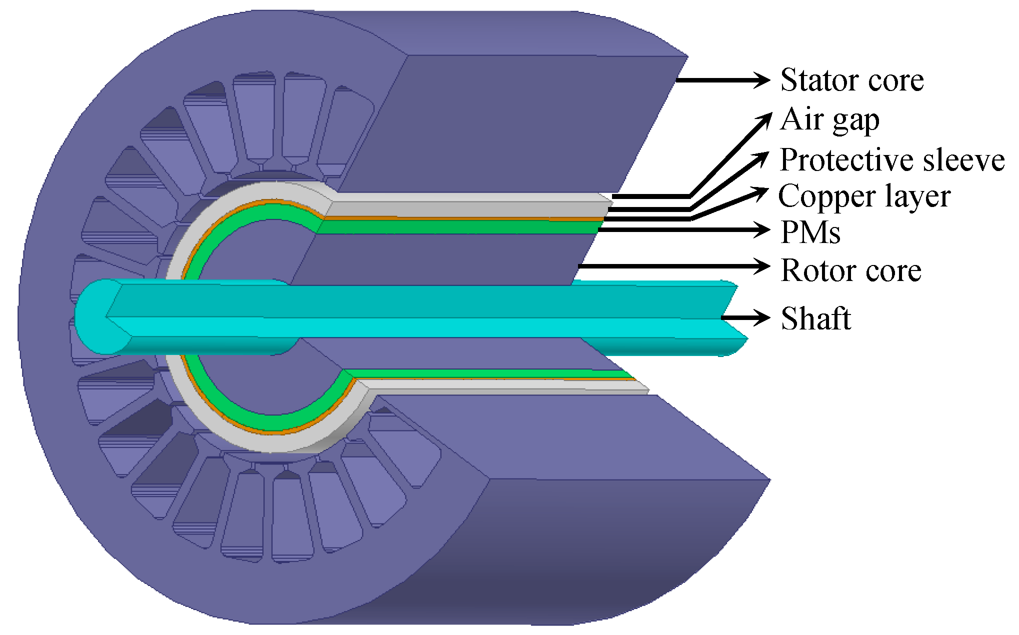
As shown in Figure 1, the analytic calculation model of the HSPMSM with the protective sleeve and copper layer can be divided into six domains, which are the stator core, air gap, protective sleeve, copper layer, PMs and rotor yoke. The detailed parameters of the high-speed permanent magnet motor are shown in Table 1.
This model assumes that:
- (1)
- The stator and rotor are expanded into a planar ferromagnetic body in a half space.
- (2)
- The stator winding current on the surface between the stator and air gap is equivalent to the sinusoidal distribution of surface current.
- (3)
- The magnetic permeability of the stator core is close to infinity and the conductivity is 0.
- (4)
- The harmonics hardly enter the rotor core area, so the eddy current losses of the rotor core are not considered in the calculation of the HSPMSM.
- (5)
- End effect is not considered.
- (6)
- All field quantities are sinusoidal over time.
The permeability of the air gap, protective sleeve, PMs and rotor yoke are μo, μr, μc, μp, μz. respectively. The conductivity of the protective sleeve, copper layer, PMs and rotor core are σr, σc, σp, σz. respectively. The thickness of the air gap, protective sleeve, copper layer, PMs and rotor yoke are da, dr, dc, dp, dz. respectively. Table 2 gives the basic parameters of the materials.
According to the established analytic model of HSPMSM, the magnetic field distribution can be determined by the Laplace equation or Poisson equation of the corresponding domain and the given boundary conditions. The magneto motive force (MMF) of each phase can be expressed as follows:
where, fa, fb, fc are separately three-phase harmonic MMF, v is the harmonic order, and N is the number of series turns per phase.
θs is the electrical angle in stationary frame, kwv is the winding factor of the vth order harmonic, and p is the number of the pole pairs. Where y1 is first pitch, τ is the fundamental pole pitch, q is the number of slots per pole, and α is the electrical angle per slot.
In stationary frame and rotating frame, the synthesis MMF of the three-phase windings can be obtained by superimposing the MMF of the three-phase independent windings, which are:
where is the synthesis MMF of the three-phase windings in stationary frame, is the synthetic MMF in the rotor rotating frame, and θr is the electrical angle in the rotor frame.
From the above formula, the synthetic MMF of the three-phase windings is not subject to time. The orders of the harmonics of the MMF are 6k ± 1th.
According to the harmonic MMF, the amplitude of the traveling wave current sheet can be obtained. The expression of the traveling wave current sheet in rotor rotating frame is:
where ra is the stator core diameter.
2.2. Calculation of the Rotor Eddy Losses in HSPMSM
Based on the coordinate system transformation of Equation (13), the rotor eddy current calculation issue can be converted to the issue in stationary 2D electromagnetic field. The magnetic vectors in each region contain only Z component.
where k1, k2 are consistent with the phase angle and frequency coefficient in the three-phase synthetic MMF formula in the rotor rotating frame and change with the v order space harmonic.
It is assumed that ωv = k1ω and τv = τ/k2, ωv is introduced by the coordinate transformation, and
In the case of sinusoidal steady-state:
The magnetic vector expression in different domains can be obtained.
In the air gap domain, the conductivity σ = 0, the magnetic vector satisfies the 2D Laplace equation.
The solution is
In the sleeve domain, copper layer domain and PMs domain, the magnetic vector satisfies the 2D complex eddy current equation.
It can be obtained that:
where:
In the rotor core domain, due to the ignorance of harmonics entering the rotor core in the HSPMSM, the conductivity of the rotor core is set as σz = 0. The component of the magnetic potential in the Z direction satisfies the 2D Laplace equation.
Equation (31) can be solved by Equation (32):
(1) The boundary condition of the surface between the stator and air gap.
Due to the permeability of stator core μFe = ∞, the magnetic field intensity in the stator iron core is 0 A/m, On the surface of the iron core, the tangential component of the magnetic field intensity equals the areal density of stator current harmonic.
where J0m is the amplitude of the traveling wave current sheet.
It can be obtained that:
(2) Because the normal component of the magnetic induction intensity and the tangential component of the magnetic field intensity are continuous, the boundary condition between the air-gap and the sleeve is Equation (37), the boundary condition between the sleeve and the copper layer is Equation (38), the boundary condition between the copper layer and the PMs is Equation (39), the boundary condition between the PMs and rotor core is Equation (40).
While , Equation (32) can be rewritten as:
According to the boundary conditions of the surface between the stator and air gap, the equations can be obtained as follows:
where, Dd = da + dr, Db = da + dr + dc, Dc = da + dr + dc + dp.
Equation (42) can be organized as the following form:
where:
The coefficients of the magnet vector can be obtained by solving Equation (42). Then, the eddy current density in the sleeve , the eddy current density in the copper layer and the eddy current density the PMs can be obtained.
Based on the formula of Joule losses, the eddy losses in the rotor sleeve Pr, the eddy losses in the copper layer Pc and the eddy losses in the PMs Pp can be solved.
where l is the axial length of the motor.
According to Equations (50)–(52), the eddy current losses in the sleeve, copper layer and PMs under the different harmonic magnetic field can be obtained. In Matlab-software environment, the sum of the losses in different domains under 5th, 7th, 11th and 13th harmonics can be separately calculated.
In this paper, through coordinate transformation, a Cartesian coordinate system has been used to calculate the rotor eddy current losses. When the thickness of air gap is relative small compared to inner diameter of stator, the curvature of the rotor can be neglected. However, the outer diameter of rotor of high speed PMSM is small while the air gap is large compared to conventional PMSM. Deviation will be caused by the assumption of the ignorance of the curvature of the rotor.
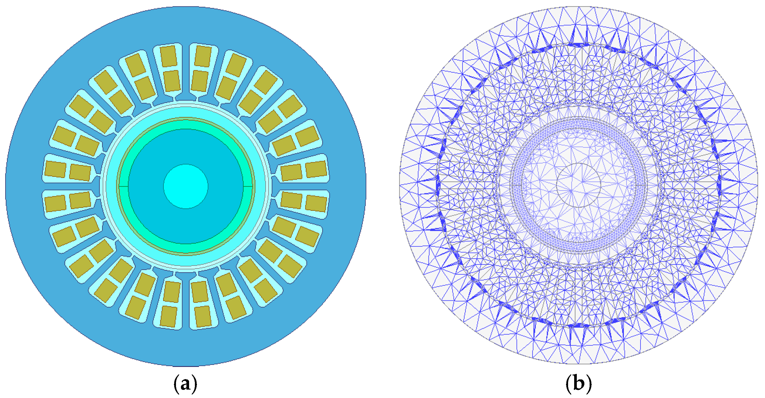
In order to verify the accuracy of the analytic calculation, a 2D finite element model that is shown in Figure 2a is built based on the ANSYS Maxwell software package. Figure 2b shows the mesh results of the model. The rotor eddy losses are calculated via 2D transient field.
The calculation time is set as 10 electric cycles, and every electric cycle has 50 steps. The highest harmonic in the analytic calculation is the 13th harmonic, thus the penetration depth in the FEA method is set as 20 times the fundamental frequency.
In comparison with the FEA results, the relative error is about 7.8%, as shown in Table 3. The error is mainly caused by the ignorance of the curvature of the rotor and higher order harmonics. If the other losses caused by higher order harmonics are considered, the differences between two methods are smaller.
3. The Influence of Rotor Structure Optimization on the Rotor Losses
According to the calculation results of the rotor eddy losses, the copper layer between the sleeve and the PMs can effectively reduce the eddy current losses. However, when the motor is operated at high speed, the harmonic magnetic field directly causes eddy current in the sleeve, which is the majority of the rotor eddy current losses, as can be seen in Table 3. Due to the complexity in the real manufacturing and processing, the metal surface treatment process is applied in rotor protective sleeve surface. When both the inner and outer surface of the rotor are coated with copper, the outer copper film reduces the eddy current losses of the rotor protective sleeve, reducing the rotor eddy current losses together with the inner copper film.
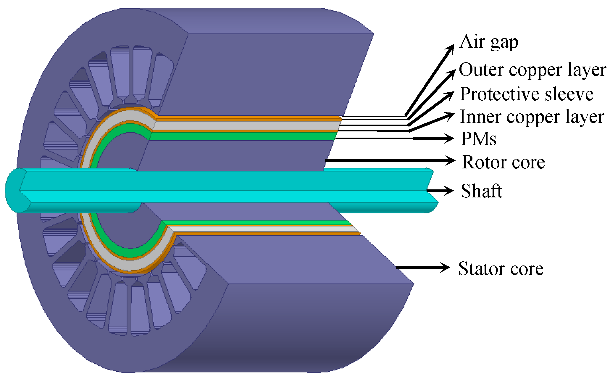
The material of the surface protective sleeve is titanium alloy and both the inner and outer surface is coated with copper. The total thickness of both layers is one millimeter. The influence of the outer copper film thickness and the inner copper film thickness on the rotor eddy current losses is reached without changing the structure and performance. The presented rotor structure is shown in Figure 3. The analytic model can be divided into seven domains, which are separately the iron core, air gap, outer copper film, sleeve, inner copper film, PMs and rotor core.
Using the method mentioned in the previous section, the equations can be obtained as Equation (53).
The magnetic permeability of the air gap, outer copper film, sleeve, inner copper film, PMs and rotor core are μ0, μc, μr, μc, μp, μz separately. The conductivity of the outer copper film, sleeve, inner copper film, PMs and rotor core are σc, σr, σc, σp, σz separately. The thickness of the air gap, outer copper film, sleeve, inner copper film, PMs and rotor core are da, do, dr, di, dp, dz separately. Because the harmonics can hardly enter the rotor core, the eddy current losses in rotor core can be ignored.
where, Dd = da + do, De = da + do + dr, Df = da + do + dr + di, Df = da + do + dr + di + dp.
The total thickness of the inner and outer copper films is one millimeter, which means that:
Equation (53) can be organized as the following form:
The coefficients of the magnet vector can be obtained by solving Equation (55). Then, the eddy current density, in the inner copper layer , the sleeve , the inner copper layer and the PMs can also be obtained.
Based on the Joule losses formula, the eddy losses in the inner copper layer Po, the rotor sleeve Pr, the inner copper layer Pi and the PMs Pp can be solved as:
where l is the axial length of the motor.
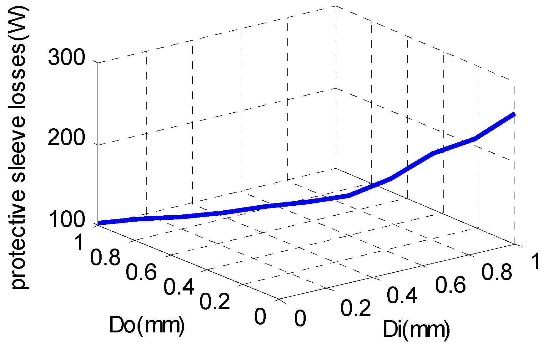
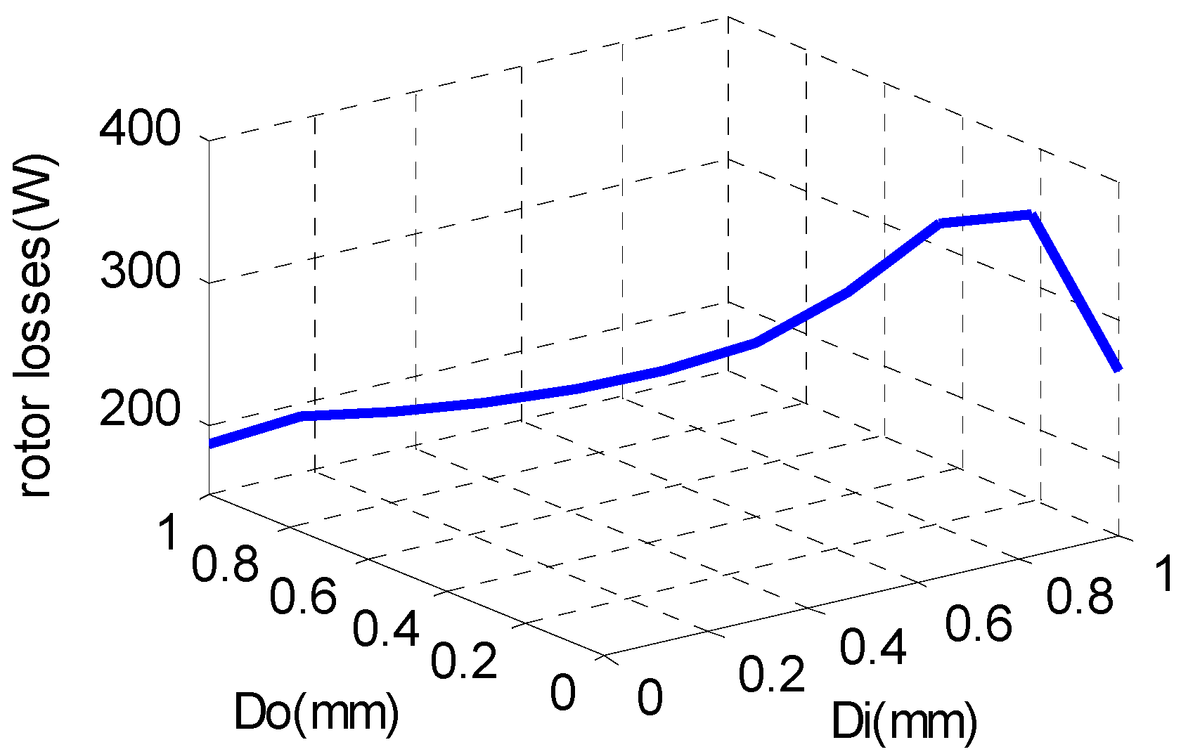
According to Equations (63)–(66), the eddy current losses in the sleeve, copper layer and the PMs under the different harmonic magnetic field can be computed. In Matlab-software environment, the sum of the losses in different domains under 5th, 7th, 11th and 13th harmonics can be separately calculated. The Figure 4, Figure 5, Figure 6, Figure 7 and Figure 8 show the rotor protection sleeve outer copper film thickness is not the same, the distribution of the various parts of the rotor eddy current losses.
As shown in the Figure 8, the sum of the eddy current losses changes with changes to the thickness of the copper films covered on the inner and outer surfaces of the sleeve. The relationship between the thickness of the copper films and the eddy current losses is nonlinear. When the thickness increasing, the eddy current losses decrease. However, when the thickness of the outer copper film is less than 0.4 mm, as can be seen from Figure 5, the eddy current losses of the outer film obviously increase.
With the further decrease of the thickness of the copper film, the eddy current losses of the copper film increase exponentially. When the thickness of the outer copper film is greater than 0.5 mm, the eddy current losses change of the copper film is not obvious.
The inner copper film can effectively reduce the intensity of the harmonics which enter the PMs, directly reducing the eddy current losses of the PMs. With the increase of the copper thickness, the eddy current losses of PMs reduce, as can be obtained from Figure 4, while the losses of inner copper film slightly increase.
From the losses results of the analytical calculation, the copper plating process on the inner and outer surface of protective sleeve can effectively reduce the total losses of the rotor. However, the actual thickness of the copper plating cannot be arbitrarily increased; in this case, only when the thickness of the copper film is greater than 0.4 mm, will the total rotor eddy current losses be significantly reduced. Therefore, by comparing the thickness of the inner and outer copper films, it is possible to find an optimal way to reduce the total losses of the rotor in the achievable process.
4. Conclusions
In this paper, the rotor structure is researched, and the rotor structure with the copper layer between the PMs and the rotor sleeve are analyzed. Combined with Maxwell equations, the analytic model for calculating the rotor eddy current losses is proposed. In comparison with the FEA results, the accuracy of the analytic method is verified. The inner and outer surfaces of the rotor protective sleeve are coated with the high-conductivity copper films, which improve the conductivity and thermal conductivity of the sleeve surfaces. By optimizing the thickness of the copper layers, the eddy current losses can be effectively reduced. Compared with the protective copper film placed between the PM and protective sleeve, the proposed scheme simplifies the processing and reduces the rotor eddy current losses, having obvious practical application.
Author Contributions
Yanan Yu and Deliang Liang conceived and designed this study. Yanan Yu wrote this manuscript. Xing Liu reviewed and edited this paper. All authors read and approved this paper.
Conflicts of Interest
The authors declare no conflict of interest.
References
- Han, S.H.; Jahns, T.M.; Zhu, Z.Q. Analysis of rotor core eddy-current losses in interior Permanent-Magnet Synchronous Machines. IEEE Trans. Ind. Appl. 2010, 46, 196–205. [Google Scholar] [CrossRef]
- Han, S.H.; Jahns, T.M.; Zhu, Z.Q. Analysis of rotor core eddy-current losses in interior permanent magnet synchronous machines. In Proceedings of the 2008 IEEE Industry Applications Society Annual Meeting, Edmonton, AB, Canada, 5–9 October 2008; pp. 1–8. [Google Scholar]
- Deiana, F.; Serpi, A.; Abrahamsson, J.; Marongiu, I.; Gatto, G. Extensive losses estimation of a novel high-speed permanent magnet synchronous machine for flywheel energy storage systems. In Proceedings of the 2016 XXII International Conference on Electrical Machines (ICEM), Lausanne, Switzerland, 4–7 September 2016; pp. 1728–1734. [Google Scholar]
- Wan, Y.; Cui, S.M.; Wu, S.P. Design and temperature rise analysis of a high speed PMSM for pulsed power system. In Proceedings of the 2015 IEEE International Conference on Applied Superconductivity and Electromagnetic Devices (ASEMD), Shanghai, China, 20–23 November 2015; pp. 177–178. [Google Scholar]
- Martin, F.; Belahcen, A.; Zaïm, M.E.H. Effect of magnet materials on optimal design of a high speed PMSM. In Proceedings of the 2015 18th International Conference on Electrical Machines and Systems (ICEMS), Pattaya City, Thailand, 25–28 October 2015; pp. 661–667. [Google Scholar]
- Yulong, P.; Xing, L.; Yi, L.; Feng, C. Effect of air gap eccentricity on rotor eddy current loss in high speed PMSM used in FESS. In Proceedings of the 2014 17th International Symposium on Electromagnetic Launch Technology, San Diego, CA, USA, 7–11 July 2014; pp. 1–6. [Google Scholar]
- Liu, X.; Du, J.; Liang, D. Analysis and speed ripple mitigation of a space vector pulse width modulation-based permanent magnet synchronous motor with a particle swarm optimization algorithm. Energies 2016, 9, 923. [Google Scholar] [CrossRef]
- Chiodetto, N.; Bianchi, N.; Alberti, L. Improved analytical estimation of rotor losses in high-speed PM synchronous machines. In Proceedings of the 2016 XXII International Conference on Electrical Machines (ICEM), Lausanne, Switzerland, 4–7 September 2016; pp. 1788–1794. [Google Scholar]
- Gengji, W.; Ping, W. Rotor loss analysis of PMSM in Flywheel Energy Storage System as Uninterruptable Power Supply. IEEE Trans. Appl. Supercond. 2016, 26, 1–5. [Google Scholar] [CrossRef]
- Wang, G.J.; Wang, P.; Wang, X.Y. Analyze of permanent magnet loss of high speed permanent magnet synchronous motor for flywheel energy storage system. In Proceedings of the 2015 IEEE International Conference on Applied Superconductivity and Electromagnetic Devices (ASEMD), Shanghai, China, 20–23 November 2015; pp. 549–550. [Google Scholar]
- Jardan, R.K.; Varga, Z.; Stumpf, P.; Nagy, I.; Endisch, C.; Sipos, P.; Simon, M. Development of a dedicated laboratory system for measurement of iron losses in high speed PMSM. In Proceedings of the 2015 IEEE International Conference on Industrial Technology (ICIT), Seville, Spain, 17–19 March 2015; pp. 708–713. [Google Scholar]
- Marashi, A.N.; Abbaszadeh, K.; Alam, F.R. Analysis and reduction of magnet eddy current losses in surface mounted permanent magnet machines. In Proceedings of the 2014 22nd Iranian Conference on Electrical Engineering (ICEE), Tehran, Iran, 20–22 May 2014; pp. 782–786. [Google Scholar]
- Lahne, H.C.; Gerling, D.; Staton, D.; Chong, Y.C. Design of a 50,000 rpm high-speed high-power six-phase PMSM for use in aircraft applications. In Proceedings of the 2016 Eleventh International Conference on Ecological Vehicles and Renewable Energies (EVER), Monte Carlo, Monaco, 6–8 April 2016; pp. 1–11. [Google Scholar]
- Gerada, D.; Mebarki, A.; Gerada, C. Optimal design of a high speed concentrated wound PMSM. In Proceedings of the 2009 International Conference on Electrical Machines and Systems, Tokyo, Japan, 15–18 November 2009; pp. 1–6. [Google Scholar]
- Zhao, L.; Chan, H.; Wu, T. A new design approach of an ultra high-speed permanent magnet synchronous motor (PMSM) system. In Proceedings of the INTERMAG 2006—IEEE International Magnetics Conference, San Diego, CA, USA, 8–12 May 2006; p. 306. [Google Scholar]
- Kim, S.I.; Kim, Y.K.; Lee, G.H.; Hong, J.P. A novel rotor configuration and experimental verification of interior PM synchronous motor for high-speed applications. IEEE Trans. Magn. 2012, 48, 843–846. [Google Scholar] [CrossRef]
- Sough, M.; Depernet, D.; Dubas, F.; Boualem, B.; Espanet, C. Analytical model of PMSM designed for high-frequency operation machine and inverter sizing compromise. In Proceedings of the 2011 IEEE Energy Conversion Congress and Exposition, Phoenix, AZ, USA, 17–22 September 2011; pp. 1436–1440. [Google Scholar]
- Zheng, L.; Wu, T.X.; Acharya, D.; Sundaram, K.B.; Vaidya, J.; Zhao, L.; Zhou, L.; Ham, C.H.; Arakere, N.; Kapat, J.; et al. Design of a super-high speed permanent magnet synchronous motor for cryogenic applications. In Proceedings of the IEEE International Conference on Electric Machines and Drives, San Antonio, TX, USA, 15–18 May 2005; pp. 874–881. [Google Scholar]
- Dubas, F.; Rahideh, A. Two-dimensional analytical permanent-magnet eddy-current loss calculations in slotless PMSM equipped with surface-inset magnets. IEEE Trans. Magn. 2014, 50, 54–73. [Google Scholar] [CrossRef]
- Rabiei, A.; Thiringer, T.; Lindberg, J. Maximizing the energy efficiency of a PMSM for vehicular applications using an iron loss accounting optimization based on nonlinear programming. In Proceedings of the 2012 XXth International Conference on Electrical Machines, Marseille, France, 2–5 September 2012; pp. 1001–1007. [Google Scholar]
- Riemer, B.; Leßmann, M.; Hameyer, K. Rotor design of a high-speed permanent magnet synchronous machine rating 100,000 rpm at 10 kW. In Proceedings of the 2010 IEEE Energy Conversion Congress and Exposition, Atlanta, GA, USA, 12–16 September 2010; pp. 3978–3985. [Google Scholar]
- Hongbo, Q.; Ran, Y.; Weili, L.; Nan, J. Influence of rectifiers on high-speed permanent magnet generator electromagnetic and temperature fields in distributed power generation systems. IEEE Trans. Energy Convers. 2015, 30, 655–662. [Google Scholar] [CrossRef]
- Weili, L.; Hongbo, Q.; Xiaochen, Z.; Ran, Y. Influence of copper plating on electromagnetic and temperature fields in a high-speed permanent-magnet generator. IEEE Trans. Magn. 2012, 48, 2247–2253. [Google Scholar] [CrossRef]
- Li, W.; Qiu, H.; Zhang, X.; Cao, J.; Yi, R. Analyses on electromagnetic and temperature fields of superhigh-speed permanent-magnet generator with different sleeve materials. IEEE Trans. Ind. Electron. 2014, 61, 3056–3063. [Google Scholar] [CrossRef]
- Li, W.; Qiu, H.; Zhang, X.; Cao, J.; Zhang, S.; Yi, R. Influence of rotor-sleeve electromagnetic characteristics on high-speed permanent-magnet generator. IEEE Trans. Ind. Electron. 2014, 61, 3030–3037. [Google Scholar] [CrossRef]
- Mlot, A.; Lukaniszyn, M.; Korkosz, M. Influence of an end-winding size on proximity losses in a high-speed PM synchronous motor. In Proceedings of the 2015 Selected Problems of Electrical Engineering and Electronics (WZEE), Kielce, Poland, 17–19 September 2015; pp. 1–6. [Google Scholar]
- Yu, Y.; Liang, D.; Liu, X.; Liang, Z.; Ze, Q. The influence on the rotor loss of the high-speed motor by optimizing the rotor structure. In Proceedings of the 2016 Eleventh International Conference on Ecological Vehicles and Renewable Energies (EVER), Monte Carlo, Monaco, 6–8 April 2016; pp. 1–4. [Google Scholar]
- Yongxiang, X.; Qingbing, Y.; Jibin, Z.; Hao, W. Influence of periodic carrier frequency modulation on stator steel core loss and rotor eddy current loss of permanent magnet synchronous motor. In Proceedings of the 2014 17th International Conference on Electrical Machines and Systems (ICEMS), Hangzhou, China, 22–25 October 2014; pp. 2094–2100. [Google Scholar]
- Nair, S.S.; Wang, J.; Chen, L.; Chin, R.; Manolas, I.; Svechkarenko, D. Computationally efficient 3D rotor eddy current loss prediction in permanent magnet machines. In Proceedings of the 2016 XXII International Conference on Electrical Machines (ICEM), Lausanne, Switzerland, 4–7 September 2016; pp. 1426–1432. [Google Scholar]
- Bernard, N.; Dang, L.; Olivier, J.C.; Bracikowski, N.; Wasselynck, G.; Berthiau, G. Design optimization of high-speed PMSM for electric vehicles. In Proceedings of the 2015 IEEE Vehicle Power and Propulsion Conference (VPPC), Montreal, QC, Canada, 19–22 October 2015; pp. 1–6. [Google Scholar]
- Hemeida, A.; Sergeant, P. Analytical modeling of surface PMSM using a combined solution of Maxwell’s equations and magnetic equivalent circuit. IEEE Trans. Magn. 2014, 50, 1–13. [Google Scholar] [CrossRef]
- Hemeida, A.; Sergeant, P. Analytical modeling of eddy current losses in Axial Flux PMSM using resistance network. In Proceedings of the 2014 International Conference on Electrical Machines (ICEM), Berlin, Germany, 2–5 September 2014; pp. 2688–2694. [Google Scholar]
Figure 1.
Rotor structure with shield. PMs: Permanent magnets.

Figure 2.
2D finite element model. (a) The schematic; and (b) mesh results.

Figure 3.
Rotor structure diagram.

Figure 4.
Losses of inner copper film.

Figure 5.
Losses of outer copper film.
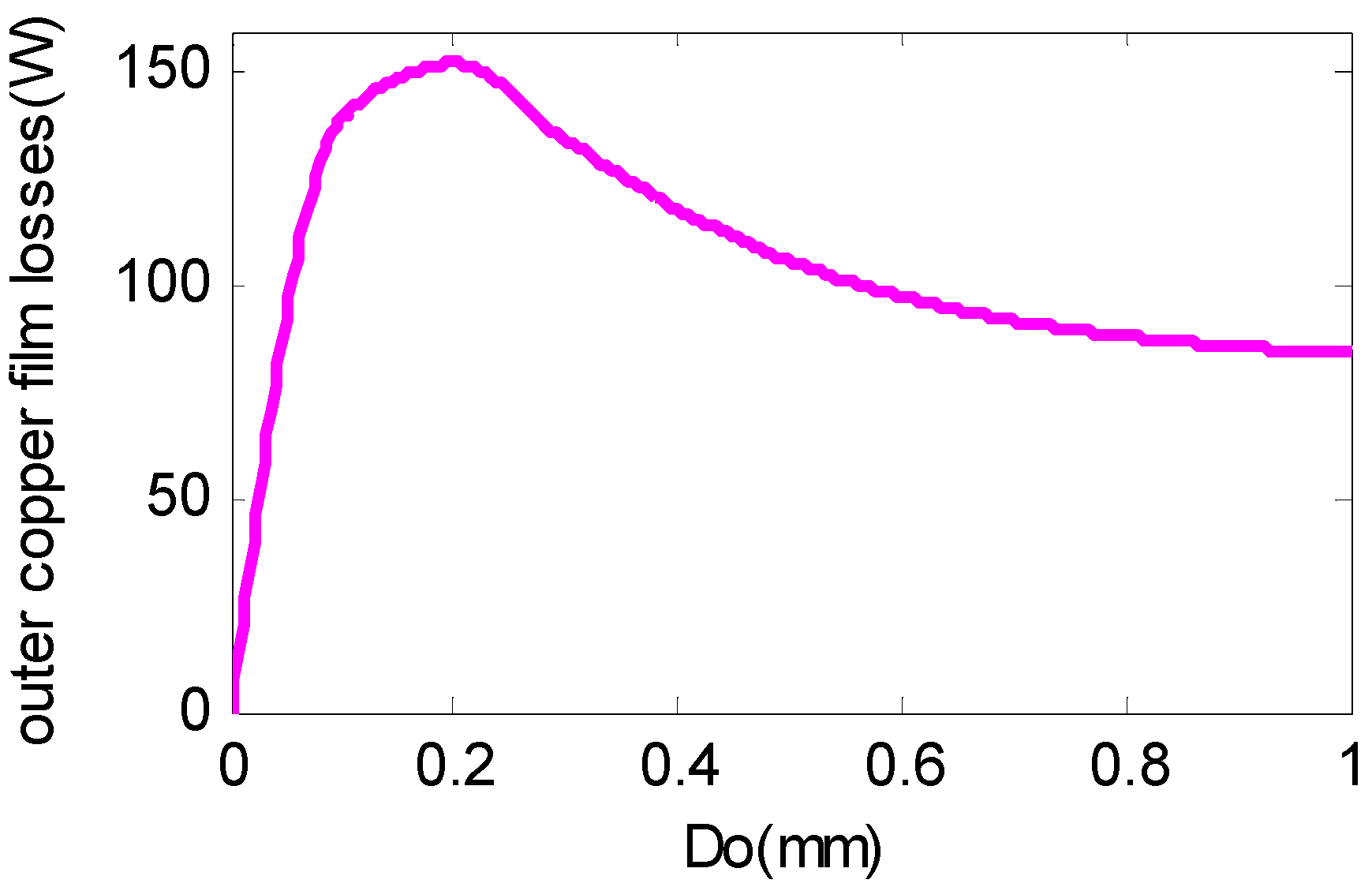
Figure 6.
Losses of protective sleeve.

Figure 7.
Losses of PMs.
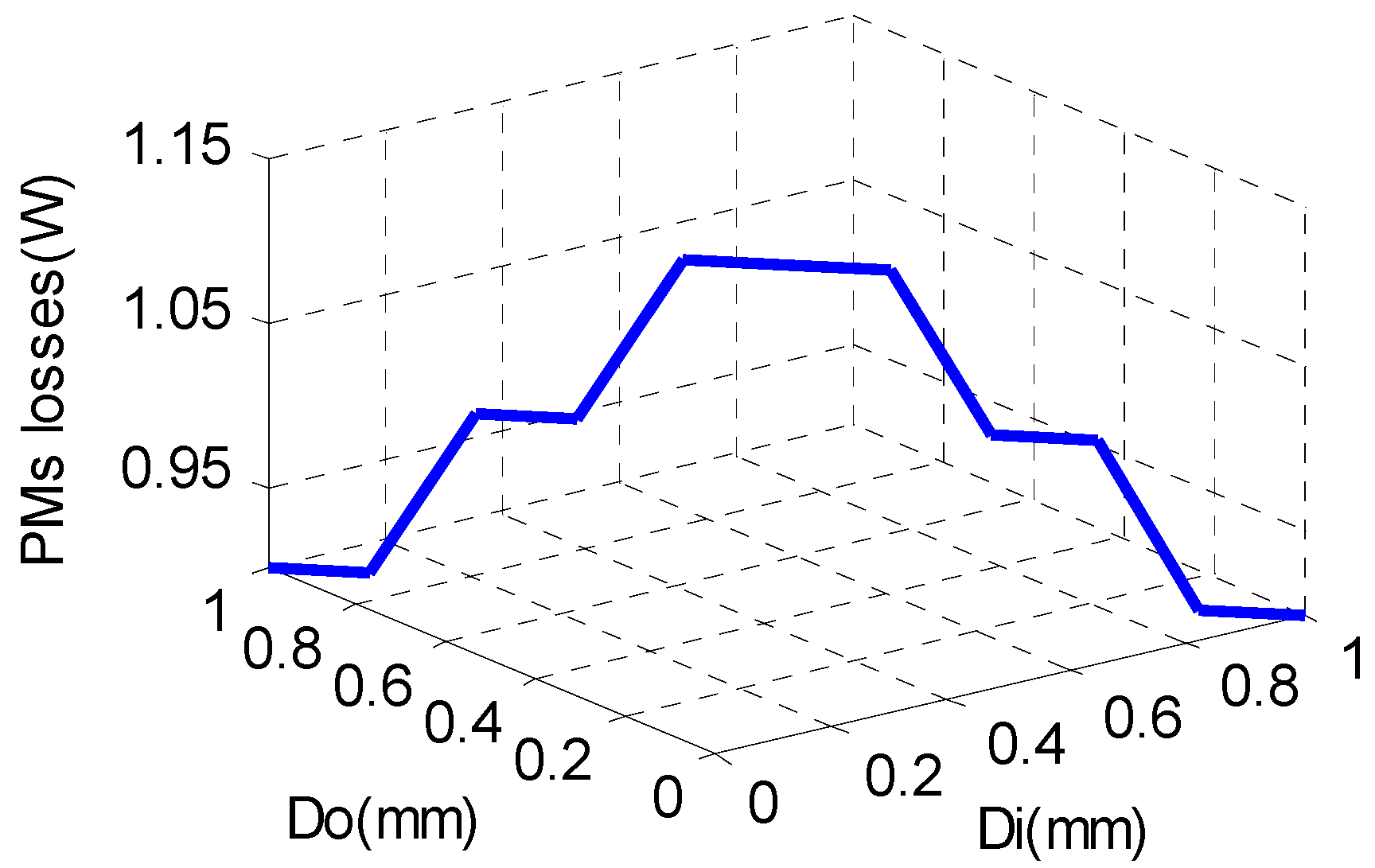
Figure 8.
Total losses of rotor.


Table 1.
Basic parameters of the high-speed permanent magnet synchronous motors (HSPMSM).
| Parameter | Value | Parameter | Value |
|---|---|---|---|
| Stator outer diameter | 135 mm | Copper layer thickness | 1 mm |
| Stator inner diameter | 66 mm | Permanent magnet thickness | 3.5 mm |
| Rotor outer diameter | 61 mm | Rated speed | 60,000 rpm |
| Protective sleeve thickness | 4 mm | Rated frequency | 1000 Hz |
Table 2.
Basic parameters of the materials.
| Relative Permeability | Value | Conductivity | Value |
|---|---|---|---|
| μo | 1 | σr | 1,315,789 S/m |
| μr | 1 | σc | 59,000,000 S/m |
| μc | 1 | σp | 1,182,791 S/m |
| μp | 1 | σz | 1,000,000 S/m |
| μz | 7000 | - | - |
Table 3.
Calculation results of the rotor eddy losses by analytic method and finite element analysis (FEA) method.
Table 3.
Calculation results of the rotor eddy losses by analytic method and finite element analysis (FEA) method.
| Symbol | Analytic Calculation Results | FEA Results |
|---|---|---|
| Pr | 239.4 W | 260.8 W |
| Pc | 4.1 W | 4.4 W |
| Pp | 0.86 W | 0.9 W |
| Pr+c+p | 244.36 W | 265.2 W |
© 2017 by the authors. Licensee MDPI, Basel, Switzerland. This article is an open access article distributed under the terms and conditions of the Creative Commons Attribution (CC BY) license (http://creativecommons.org/licenses/by/4.0/).
Share and Cite
MDPI and ACS Style
Yu, Y.; Liang, D.; Liu, X. Optimal Design of the Rotor Structure of a HSPMSM Based on Analytic Calculation of Eddy Current Losses. Energies 2017, 10, 551. https://doi.org/10.3390/en10040551
AMA Style
Yu Y, Liang D, Liu X. Optimal Design of the Rotor Structure of a HSPMSM Based on Analytic Calculation of Eddy Current Losses. Energies. 2017; 10(4):551. https://doi.org/10.3390/en10040551
Chicago/Turabian StyleYu, Yanan, Deliang Liang, and Xing Liu. 2017. "Optimal Design of the Rotor Structure of a HSPMSM Based on Analytic Calculation of Eddy Current Losses" Energies 10, no. 4: 551. https://doi.org/10.3390/en10040551
Note that from the first issue of 2016, this journal uses article numbers instead of page numbers. See further details here.