
Power-Smoothing Scheme of a DFIG Using the Adaptive Gain Depending on the Rotor Speed and Frequency Deviation


1
Department of Electrical Engineering and Wind Energy Grid-Adaptive Technology (WeGAT) Research Center, Chonbuk National University, Chonju 54896, Korea
2
National Renewable Energy Laboratory, Golden, CO 80401, USA
3
Department of Wind Energy, Technical University of Denmark, 4000 Roskilde, Denmark
4
Department of Electrical Engineering, WeGAT Research Center, and Smart Grid Research Center, Chonbuk National University, Chonju 54896, Korea
*
Author to whom correspondence should be addressed.
Energies 2017, 10(4), 555; https://doi.org/10.3390/en10040555
Submission received: 16 December 2016
/
Revised: 4 April 2017
/
Accepted: 5 April 2017
/
Published: 18 April 2017
Abstract
:In an electric power grid that has a high penetration level of wind, the power fluctuation of a large-scale wind power plant (WPP) caused by varying wind speeds deteriorates the system frequency regulation. This paper proposes a power-smoothing scheme of a doubly-fed induction generator (DFIG) that significantly mitigates the system frequency fluctuation while preventing over-deceleration of the rotor speed. The proposed scheme employs an additional control loop relying on the system frequency deviation that operates in combination with the maximum power point tracking control loop. To improve the power-smoothing capability while preventing over-deceleration of the rotor speed, the gain of the additional loop is modified with the rotor speed and frequency deviation. The gain is set to be high if the rotor speed and/or frequency deviation is large. The simulation results based on the IEEE 14-bus system clearly demonstrate that the proposed scheme significantly lessens the output power fluctuation of a WPP under various scenarios by modifying the gain with the rotor speed and frequency deviation, and thereby it can regulate the frequency deviation within a narrow range.
1. Introduction
For an electric power grid that has a high penetration level of wind, the high fluctuation of wind causes difficulties in regulating the system frequency within a narrow range [1,2,3,4,5,6]. This is because variable-speed wind turbine generators (WTGs), such as doubly-fed induction generators (DFIGs) and fully-rated converter-based WTGs, perform maximum power point tracking (MPPT) control, which is unable to mitigate the fluctuating output power of the WTGs caused by the continuously varying wind speeds. To minimize these problems, some countries specify requirements on the ramp rates of the output power of a wind power plant (WPP) [7].
Power-smoothing schemes of WTGs can be divided into two groups: those with or without energy storage systems (ESSs) [8,9,10,11,12]. In [8,9,10], ESSs such as flywheels, supercapacitors, or batteries were suggested to smooth the frequency fluctuation caused by WTGs. ESSs help mitigate the frequency fluctuation by using their stored energy; however, these devices require an extra cost for installation and maintenance, particularly for a large-scale WTG.
To avoid or reduce the additional cost for the ESS, power-smoothing schemes have been suggested that release or absorb the kinetic energy stored in the rotating masses of a WTG. These schemes use additional control loops operating in conjunction with the MPPT control loop: the rate-of-change-of-frequency (ROCOF) loop and/or frequency deviation loop [11,12]. These loops help smooth the frequency fluctuation; however, these schemes use the fixed gain for additional control loops. A large gain can improve the power-smoothing capability of a WTG, but it is unable to prevent over-deceleration of the rotor speed in the low-rotor-speed region; thus, to avoid this, the use of a small gain is inevitable, thereby providing a limited contribution to mitigating the frequency fluctuation.
This paper proposes a power-smoothing scheme of a DFIG to regulate the frequency deviation within a narrow range. The proposed scheme uses an additional control loop relying on the frequency deviation operating in conjunction with the MPPT control loop. To improve the power-smoothing capability while preventing over-deceleration of the rotor speed, the gain of the additional control loop varies with the rotor speed and frequency deviation. The performance of the proposed scheme is investigated under various scenarios, including continuously varying wind conditions for two wind power penetration levels in the IEEE 14-bus system using an EMTP-RV simulator.
2. Proposed Power-Smoothing Scheme of a DFIG
2.1. DFIG Model
Figure 1a shows a typical configuration of a DFIG, which includes a mechanical power model, two-mass shaft model, back-to-back converters, and a pitch control model.
The mechanical power extracted from the wind (Pm) is defined as:
where ρ, A, vw, cp, λ, and β are the air density, rotor-swept area by blades, wind speed, power coefficient, tip-speed ratio, and pitch angle, respectively.
In this paper, the maximum cp and optimal λ for β = 0° are set to 0.5 and 9.95, respectively.
The drivetrain system is modeled as a two-mass shaft model for the dynamics between the low-speed turbine and high-speed generator. A two-mass shaft model is represented by:
where Ht, Hg, ωt, ωr, Tt, Tg, Dt, and Dg are the inertia time constants, angular speeds, torques, and damping constants of a wind turbine and generator mass, respectively; and Ks, Ds, θs, and ω are the shaft stiffness, damping constant, torsional twist, and base value of the angular speed, respectively [14]. In this paper, the parameters are set as follows: Ht = 4 s, Hg = 1 s, Ks = 1.25 p.u., Ds = 1.5 p.u., Dg = 0 p.u., and Dt = 0 p.u.
Figure 1b shows an electrical equivalent circuit of an induction generator. When the Park’s transformation is applied, the rotor and stator voltage equations of an induction generator in the d-q reference frame can be written as:
where vds and vqs are the stator voltages in the d- and q-axis, respectively; vdr and vqr are the rotor voltages in the d- and q-axis, respectively; ids and iqs are the stator currents in the d- and q-axis, respectively; idr and iqr are the rotor currents in the d- and q-axis, respectively; rs and rr are the rotor and stator resistances, respectively; ψds and ψqs are the stator flux linkages in the d- and q-axis, respectively; ψdr and ψqr are the rotor flux linkages in the d- and q-axis, respectively; and rs and rr are set to 0.023 p.u. and 0.016 p.u., respectively.
The flux linkages for the stator and rotor windings can be represented as:
where ls, lr, and lm are the stator, rotor, and magnetizing inductances, respectively; and they are set to 3.1 p.u., 0.16 p.u., and 2.9 p.u., respectively.
The DFIG controller comprises a rotor-side converter (RSC), grid-side converter (GSC), and pitch-angle controller, as shown in Figure 1a. An RSC controls the active power injected into an electric power grid and the reactive current (idr) to regulate the stator terminal (see Figure 1c); in addition, a GSC controls the DC-link and terminal voltages (see Figure 1d) [15]. To extract the maximum power from the wind, the reference for the MPPT control (PMPPT) is set to (13), as in [16]:
where kg is constant, and it is set to 0.512 in this paper.
A pitch-angle controller is used to prevent ωr from exceeding the maximum operating limit (ωmax), as shown in Figure 1e. To obtain realistic results, this paper includes the rate and angle limiters, which are set to ±10°/s and 30°, respectively.
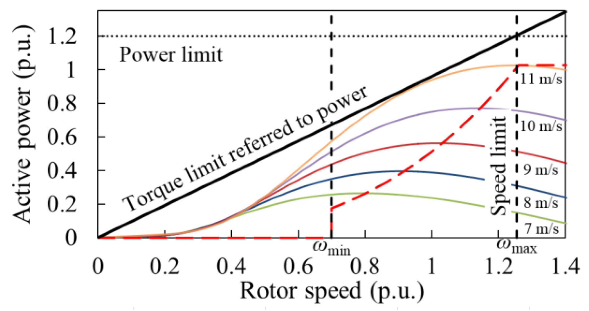
In addition, the excessive increase of output power may cause mechanical stresses [17,18]. To avoid these, this paper considers the torque, power, and rate limits, as shown in Figure 2. The active power limit (Plimit) and the torque limit (Tlimit) are set to 1.20 p.u. and 1.17 p.u., respectively [18]. The rate limit is set to 0.45 p.u./s [19]. The operating range of ωr is from 0.7 p.u. (ωmin) to 1.25 p.u. (ωmax).
2.2. Conventional Power-Smoothing Scheme in [12]
Conventional power-smoothing schemes of a DFIG rely on the ROCOF and/or frequency deviation (Δf). The proposed scheme uses the Δf loop only, as in the conventional scheme in [12], because the ROCOF loop is prone to noise components contained in the measured system frequency. This subsection briefly describes the features of the conventional scheme in [12].
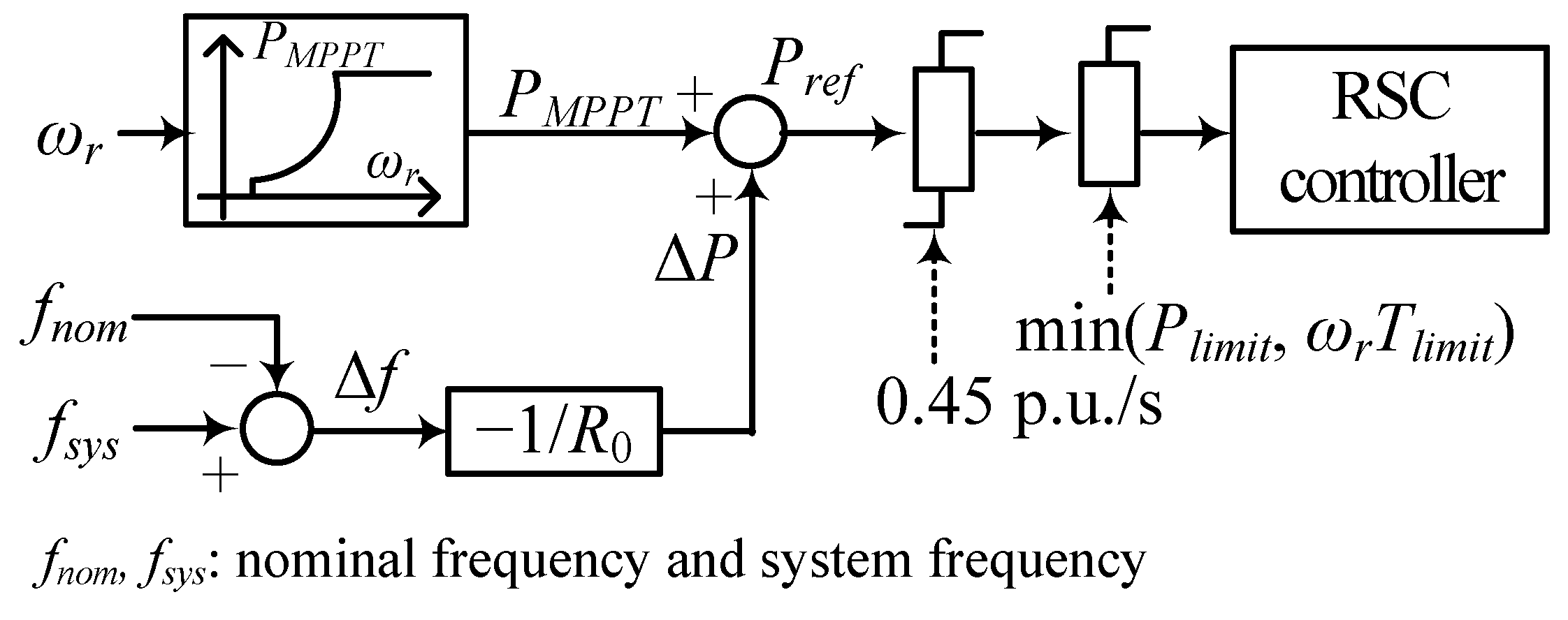
Figure 3 shows the conventional power-smoothing scheme of a DFIG in [12], which is implemented in the RSC controller. The power reference (Pref) in [12] consists of PMPPT and the output of the Δf loop (ΔP) as in:
In the conventional scheme, ΔP in (14) is determined as:
where 1/R0 is the fixed gain of the Δf loop, and in this paper it is set to 25 to prevent over-deceleration of the rotor speed for the low-rotor-speed region [11].
2.3. Proposed Power-Smoothing Scheme Using the Adaptive Gain with the Rotor Speed and Δf
In the conventional scheme, the gain of the Δf loop is set to be the small value of 25 irrespective of the stored kinetic energy. Thus, the conventional scheme provides a limited contribution to smoothing the power fluctuation, even though there is a large amount of kinetic energy in the rotating masses of a WTG.
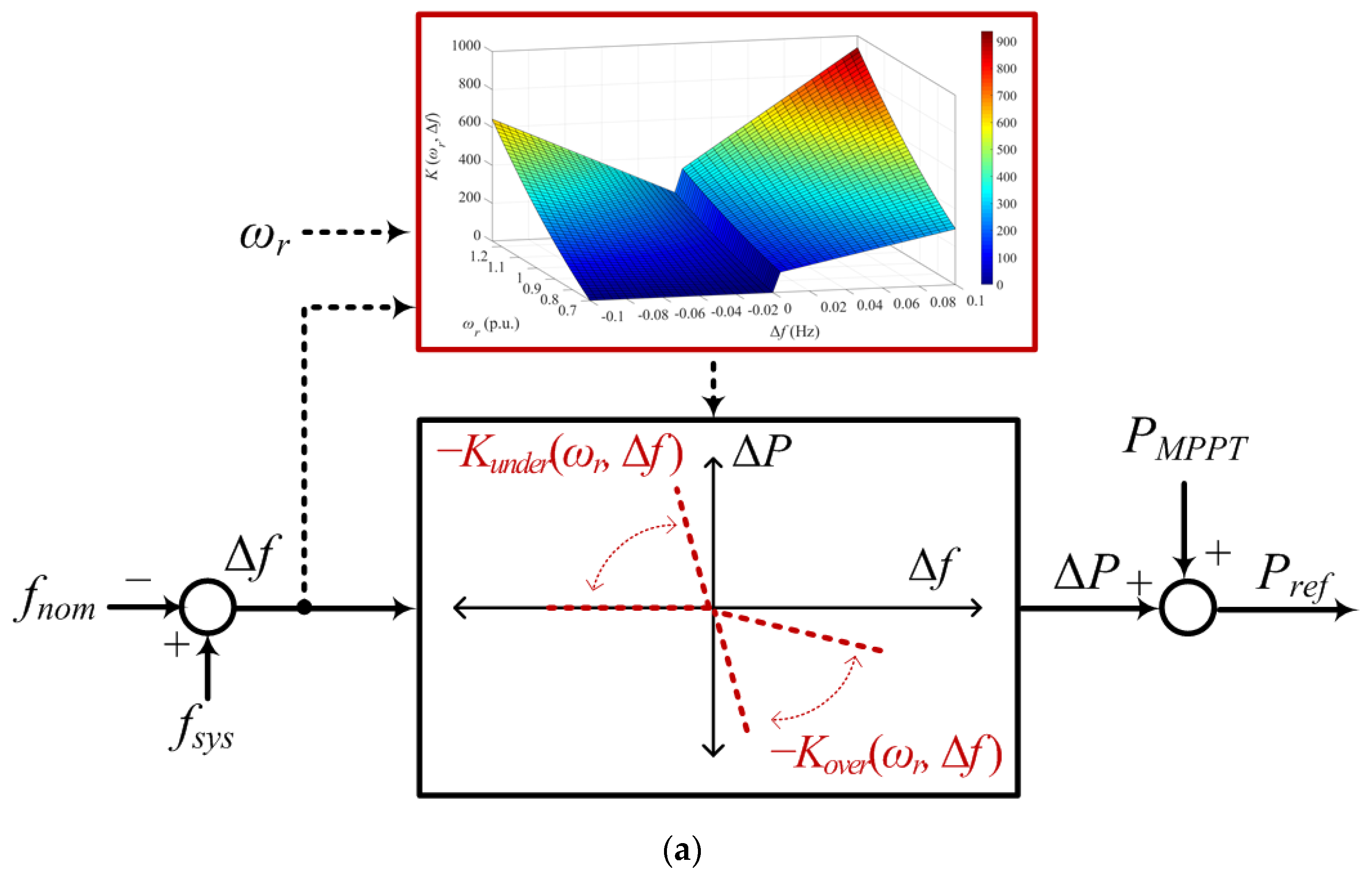
Figure 4 shows the operational characteristics of the proposed scheme, which aims to improve the power-smoothing capability of a DFIG while preventing over-deceleration of the rotor speed. To achieve this objective, the proposed scheme suggests the adaptive gain of the Δf loop (K (ωr, Δf)) modifying with ωr and Δf.
In the proposed scheme, ΔP is determined as:
where KUF (ωr, Δf) and KOF (ωr, Δf) are the gains of the Δf loop, and they are separately defined in the under- and over-frequency regions, respectively, as in:
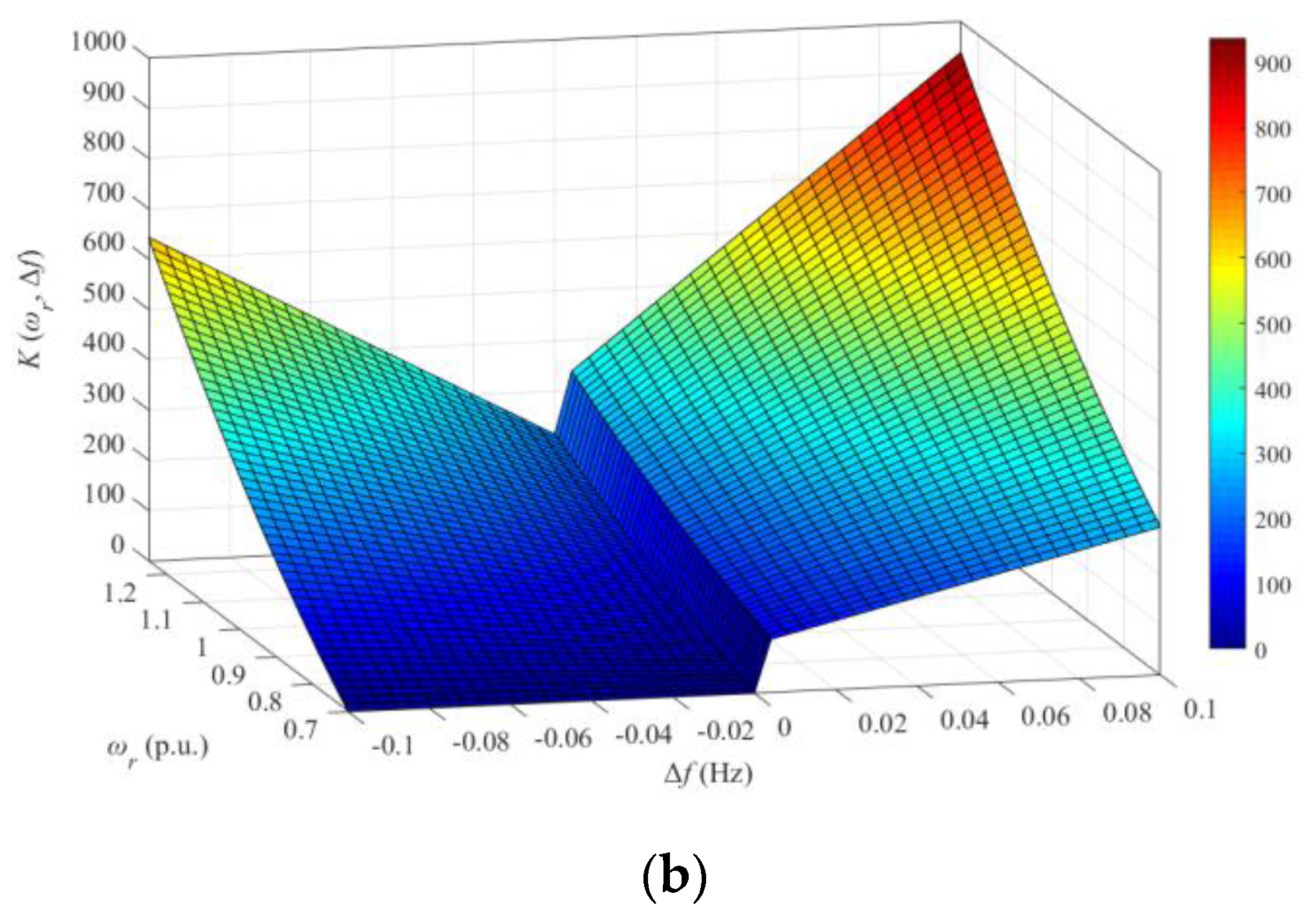
where C0 and a are the constants, and they are set to 200 and 20 in this paper, respectively. C0 and a can be determined in many ways depending on the design purposes and system conditions. A larger value of C0 and a can be used to increase ΔP at any ωr and Δf.
To improve the power-smoothing capability of a DFIG, both KUF and KOF are set to be proportional to the stored kinetic energy; this means that the gain becomes large if there is a large amount of stored kinetic energy; otherwise, the gain becomes small. However, KUF is set to be proportional to (ωr2 − ωmin2), and KOF is set to be proportional to ωr2. The reason for this is as follows. To mitigate the frequency fluctuation, a DFIG should release kinetic energy in the under-frequency region to increase the frequency, but it should absorb kinetic energy in the over-frequency region to reduce the frequency. To prevent over-deceleration of a DFIG in the under-frequency region, KUF is set to zero at ωr = ωmin.
Further, to suppress the large frequency deviation, the magnitude of KUF and KOF increases as the magnitude of Δf increases. The increase rate depends on a. This means that a can be set to be large to attain high power-smoothing capability as Δf increases. Thus, the proposed scheme can significantly mitigate the frequency fluctuation as Δf increases.
As shown in Figure 4b, it can be concluded that KUF and KOF depend on ωr and Δf; they are set to be large if the kinetic energy and/or magnitude of Δf is large.
3. Model System
Figure 5 shows the IEEE 14-bus system used to validate the proposed power-smoothing scheme using an EMTP-RV simulator. The system includes five synchronous generators, static loads, and two aggregated DFIG-based WPPs. The parameters of the synchronous generators [20] and the load consumptions of the buses are shown in Figure 5. The droop gains of all of the synchronous generators are set to 5%, which is the typical droop setting of the synchronous generators used in Korea’s power system. To simulate an electric power grid that has a low ramping capability, all of the generators are assumed to be steam turbines; the steam turbine governor model is the IEEEG1 [21]. The total static load is set to approximately 600 MW and 57.4 MVAr.
4. Case Studies
The system frequency of an electric power grid with a high penetration level of wind fluctuates because of the wind speed variation. This section investigates the performance of the power-smoothing schemes under the scenarios by continuously varying the wind speeds for the wind power penetration levels set to 16.7% and 33.3%, which indicate the installed capacity of each WPP of 50 MW and 100 MW, respectively. In this paper, the wind power penetration level is defined as the installed capacity of a WPP divided by the load [22].
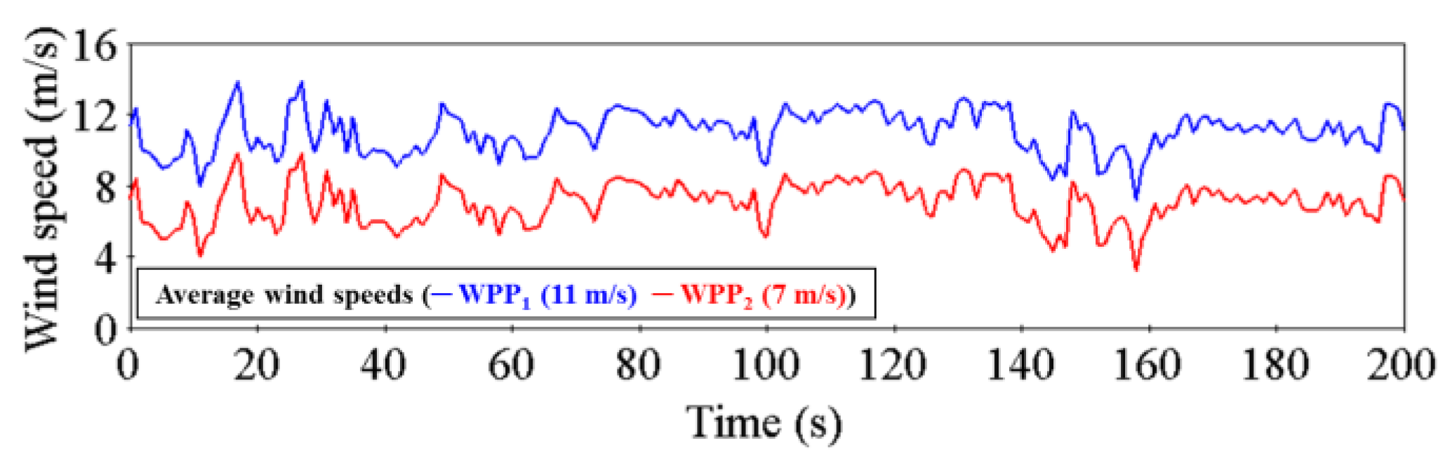
Figure 6 shows the input wind speeds of two WPPs, which have the same pattern with different average wind speeds: 7 m/s for WPP2 and 11 m/s for WPP1. The performance of the proposed scheme is compared to that of the conventional scheme in [12] with the fixed gain of 25 and to a case that performs MPPT operation. In all schemes, if ωr reaches ωmax, a pitch-angle controller is activated.
4.1. Case 1: Wind Power Penetration Level of 16.7%
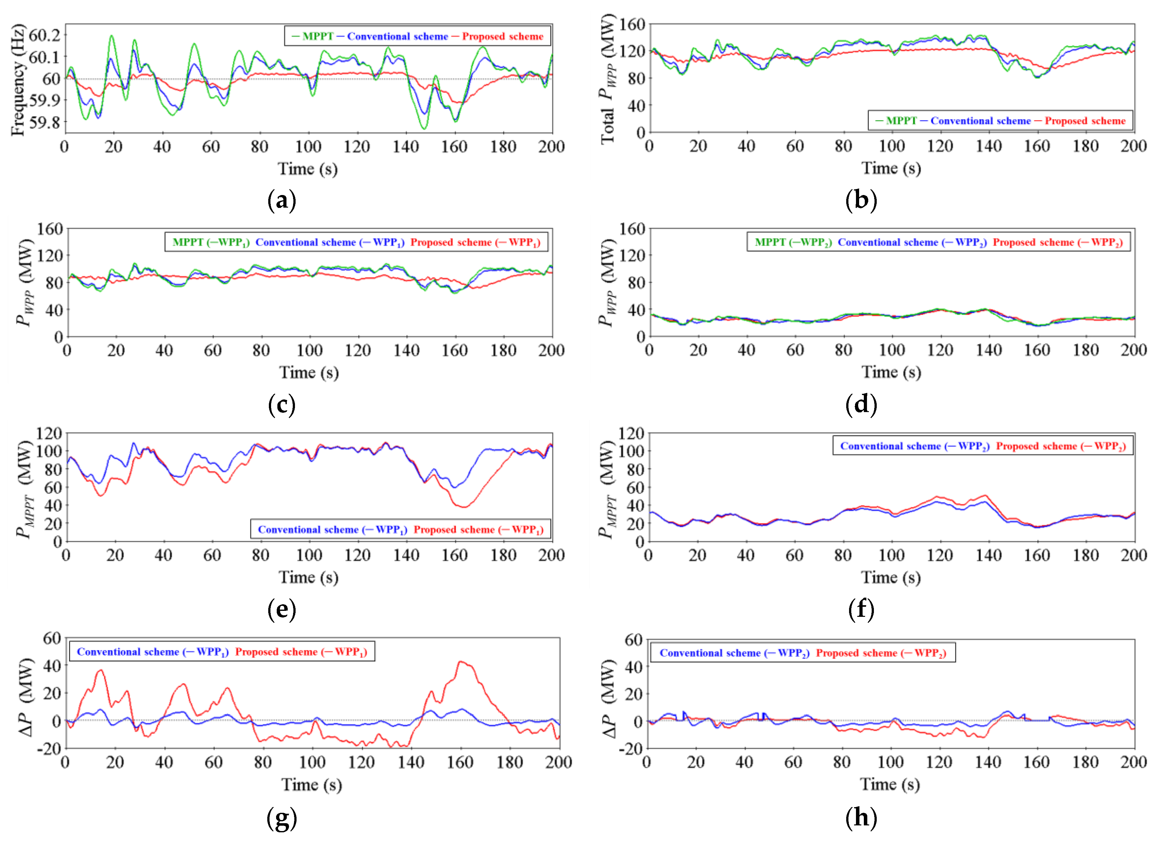
This subsection investigates the performance of the power-smoothing schemes under the varying wind speeds in the wind power penetration level of 16.7%. As shown in Figure 7a, in the proposed scheme, the frequency fluctuation is significantly mitigated compared to the conventional scheme because the proposed scheme significantly smooths the total output power of the WPPs by modifying the control gain with ωr and Δf (see Figure 7b).
As shown in Table 1, the root mean square (RMS) values of Δf in the conventional and proposed schemes are 84% and 47% of that of MPPT operation, respectively. In addition, the maximum frequency deviations (Δfmax) in the conventional and proposed schemes are 73% and 20% of that of MPPT operation, respectively; in contrast, the minimum frequency deviations (Δfmin) in the conventional and proposed schemes are 88% and 62% of that of MPPT operation, respectively. This means that the proposed scheme provides better performance in regulating the frequency deviation in the over-frequency region than in the under-frequency region. This is because KOF in (17) is larger than KUF.
As shown in Figure 7c,d, the proposed scheme shows better performance as the wind speed increases. This is because K (ωr, Δf) of WPP1 (high wind speed) is larger than that in WPP2 (low wind speed) (see Figure 7i,j); subsequently, the ΔP of WPP1 is significantly larger than that of WPP2.
In the proposed scheme, ωr varies more widely than it does in the conventional scheme because K (ωr, Δf) in the proposed scheme is significantly larger than that in the conventional scheme; this means that the proposed scheme utilizes the operating range of ωr more than the conventional scheme. In addition, in the proposed scheme, the operating range of ωr for WPP1 is larger than that of WPP2. This means that ωr varies more widely as the wind speed increases in the proposed scheme.
In all schemes, the pitch-angle controller is activated for WPP1 when ωr reaches ωmax (see Figure 7m); however, the pitch angle of the proposed scheme is larger than that in the conventional scheme because of the larger gain.
4.2. Case 2: Wind Power Penetration Level of 33.3%
As the wind power penetration level increases, the system frequency fluctuation is more severe when the wind speed is continuously varying. Thus, this subsection investigates the performance of the power-smoothing schemes for a higher wind power penetration level.
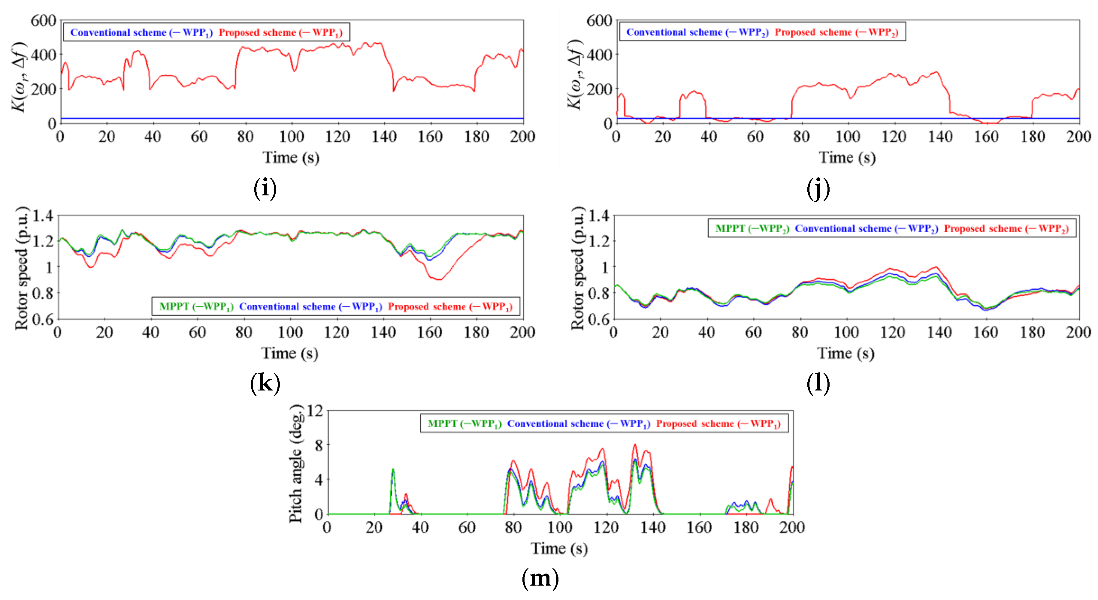
Figure 8 shows the results for Case 2, which is identical to Case 1 except for a wind power penetration level of 33.3%. As expected, in this case, the frequency fluctuation is more severe than it is in Case 1. As in Case 1, the frequency fluctuation is significantly mitigated compared to the conventional scheme (see Figure 8a). In addition, in this case the proposed scheme can smooth the frequency fluctuation more than it does in Case 1; compare Figure 8a with Figure 7a.
As in Case 1, the proposed scheme provides better performance to smoothing the frequency fluctuation in the over-frequency region than in the under-frequency region. The RMS values of Δf in the conventional and proposed schemes are 78% and 38% of that of MPPT operation, respectively (see Table 2). The values of Δfmax in the conventional and proposed schemes are 65% and 13% of that of MPPT operation, respectively; and the values of Δfmin in the conventional and proposed schemes are 81% and 48% of that of MPPT operation, respectively. Further, the proposed scheme provides a better contribution to lessening the frequency fluctuation as the wind speed increases.
In this case, at approximately 15 s, 45 s, and 160 s, ΔP of the conventional scheme is temporarily set to zero because ωr of WPP2 reaches ωmin. This is because ΔP is larger than that in Case 1 because of the larger frequency deviation (see Figure 8h).
As in Case 1, in the proposed scheme ωr varies more widely than it does in the conventional scheme because of the large gain; the pitch-angle controller is activated for WPP1 if ωr reaches ωmax.
5. Conclusions
This paper proposes a power-smoothing scheme of a DFIG relying on the frequency deviation loop, the gain of which is modified depending on the rotor speed and frequency deviation. To enhance the power-smoothing capability of a DFIG while preventing over-deceleration of the rotor speed, the control gain in the over-frequency region is set to be higher than that in the under-frequency region. Further, the gain increases if the frequency deviation increases.
Simulation results clearly demonstrate that the proposed scheme significantly smooths the output power fluctuation of a DFIG by adjusting the control gain of the frequency deviation loop, thereby mitigating the frequency fluctuation caused by varying wind speeds. In addition, the proposed scheme provides better performance when the wind speed increases and/or wind power penetration level is high.
The advantages of the proposed scheme are that it can significantly mitigate the DFIG’s output power fluctuation by releasing or absorbing the kinetic energy under continuously varying wind speeds; therefore, it can regulate the frequency deviation into a narrow range in an electric power grid that has a high level of wind penetration. Thus, it will help reduce the size of the ESS required to regulate the frequency fluctuation caused by varying wind speeds.
Acknowledgments
This work was supported in part by the National Research Foundation of Korea (NRF) grant funded by the Korea government (MSIP) (No. 2010-0028509) and in part by the Energy Efficiency & Resources of the Korea Institute of Energy Technology Evaluation and Planning (KETEP) grant funded by the Korea government Ministry of Trade, Industry & Energy (2012T100201551). The National Renewable Energy Laboratory’s (NREL’s) contribution to this work was supported by the U.S. Department of Energy under Contract no. DE-AC36-08-GO28308 with NREL. Funding provided by DOE Wind Energies Technologies Office.
Author Contributions
All the authors contributed to publish this paper. Hyewon Lee, Min Hwang, and Yong Cheol Kang mainly proposed the scheme of this paper. Hyewon Lee and Min Hwang carried out the simulation tests; Eduard Muljadi, Poul Sørensen, and Yong Cheol Kang revised the original scheme. Writing was done by Hyewon Lee, Min Hwang, Eduard Muljadi, Poul Sørensen, and Yong Cheol Kang. Final review was also done by Hyewon Lee, Min Hwang, Eduard Muljadi, Poul Sørensen, and Yong Cheol Kang.
Conflicts of Interest
The authors declare no conflict of interest.
References
- Bevrani, H. Robust Power System Frequency Control, 2nd ed.; Springer: New York, NY, USA, 2014. [Google Scholar]
- Alegría, I.M.; Andreu, J.; Martín, J.L.; Ibañez, P.; Villate, J.L.; Camblong, H. Connection requirements for wind farms: A survey on technical requirements and regulation. Renew. Sustain. Energy Rev. 2007, 11, 1858–1872. [Google Scholar] [CrossRef]
- Eriksen, P.B.; Ackermann, T.; Abildgaard, H.; Smith, P.; Winter, W.; Garcia, J.R. System operation with high wind penetration. IEEE Power Energy Mag. 2005, 3, 65–74. [Google Scholar] [CrossRef]
- Liserre, M.; Cardenas, R.; Molinas, M.; Rodriguez, J. Overview of multi-MW wind turbines and wind parks. IEEE Trans. Ind. Electron. 2011, 58, 1081–1095. [Google Scholar] [CrossRef]
- Ekanayake, J.B.; Jenkins, N. Comparison of the response of doubly-fed and fixed-speed induction generator wind turbines to changes in network frequency. IEEE Trans. Energy Convers. 2004, 19, 800–802. [Google Scholar] [CrossRef]
- Lalor, G.; Mullane, A.; O’Malley, M. Frequency control and wind turbine technologies. IEEE Trans. Power Syst. 2005, 20, 1905–1913. [Google Scholar] [CrossRef]
- Fagan, E.; Grimes, S.; McArdle, J.; Smith, P.; Stronge, M. Grid code provisions for wind generators in Ireland. In Proceedings of the 2005 IEEE Power Engineering Society General Meeting, San Francisco, CA, USA, 12–16 June 2005. [Google Scholar]
- D’ıaz-Gonz’alez, F.; Bianchi, F.D.; Sumper, A.; Gomis-Bellmunt, O. Control of a flywheel energy storage system for power smoothing in wind power plants. IEEE Trans. Energy Convers. 2014, 29, 204–214. [Google Scholar] [CrossRef]
- Pegueroles-Queralt, J.; Bianchi, F.D.; Gomis-Bellmunt, O. A power smoothing system based on supercapacitors for renewable distributed generation. IEEE Trans. Ind. Electron. 2015, 62, 343–350. [Google Scholar] [CrossRef]
- Xiangjun, L.; Dong, H.; Xiaokang, L. Battery energy storage station (BESS)-based smoothing control of photovoltaic (PV) and wind power generation fluctuations. IEEE Trans. Sustain. Energy 2013, 4, 464–473. [Google Scholar]
- Margaris, I.D.; Papathanassiou, S.A.; Hatziargyriou, N.D.; Hansen, A.D.; Sørensen, P. Frequency control in autonomous power systems with high wind power penetration. IEEE Trans. Sustain. Energy 2012, 3, 189–199. [Google Scholar] [CrossRef]
- Wang-hansen, M.; Josefsson, R.; Mehmendovic, H. Frequency controlling wind power modeling of control strategies. IEEE Trans. Sustain. Energy 2013, 4, 954–959. [Google Scholar] [CrossRef]
- Yang, S. Novel Sensorless Generator Control and Grid Fault Ride-through Strategies for Variable-Speed Wind Turbines and Implementation on a New Real-Time Simulation Platform. Ph.D. Thesis, Department of Electrical and Computer Engineering, Iowa State University, Ames, Iowa, 2010. [Google Scholar]
- Ye, R.-J.; Li, H.; Chen, Z.; Gao, Q. Comparison of transient behaviors of wind turbines with DFIG considering the shaft flexible models. In Proceedings of the 2008 IEEE International Conference on Electrical Machines and Systems (ICEMS), Wuhan, China, 17–20 October 2008. [Google Scholar]
- Lie, X.; Yi, W. Dynamic modelling and control of DFIG-based wind turbines under unbalanced network conditions. IEEE Trans. Power Syst. 2007, 22, 314–323. [Google Scholar]
- Shen, B.; Mwinyiwiwa, B.; Zhang, Y.; Ooi, B. Sensorless maximum power point tracking of wind by DFIG using rotor position phase lock loop. IEEE Trans. Power Electron. 2009, 24, 942–951. [Google Scholar] [CrossRef]
- Wang, Y.; Delille, G.; Bayem, H.; Guilaud, X.; Francois, B. High wind power penetration in isolated power systems—Assessment of wind inertial and primary frequency responses. IEEE Trans. Power Syst. 2013, 28, 2412–2420. [Google Scholar] [CrossRef]
- Mauricio, J.M.; Marano, A.; Gómez-Expósito, A.; Ramos, J.L.M. Frequency regulation contribution through variable-speed wind energy conversion systems. IEEE Trans. Power Syst. 2009, 24, 173–180. [Google Scholar] [CrossRef]
- Clark, K.; Miller, N.W.; Sanchez-Gasca, J.J. Modeling of GE Wind Turbine-Generators for Grid Studies, version 4.5; GE Energy: Schenectady, NY, USA, 2010. [Google Scholar]
- Sutter, J.; Maleche, J.; Muriithi, C. Analysis of power system transient stability due to increased integration of geothermal power. In Proceedings of the 39th Workshop on Geothermal Reservoir Engineering, Stanford, CA, USA, 24–26 February 2014. [Google Scholar]
- Byerly, R.T.; Aanstad, O.; Berry, D.H.; Dunlop, R.D.; Ewart, D.N.; Fox, B.M.; Johnson, L.H.; Tschappat, D.W. Dynamic models for steam and hydro turbines in power system studies. IEEE Trans. Power Appar. Syst. 1973, 92, 1904–1915. [Google Scholar]
- Ackermann, T. Wind Power in Power Systems, 2nd ed.; John Wiley & Sons, Ltd.: Chichester, UK, 2012. [Google Scholar]
Figure 1.
Typical topology and pitch control scheme of a doubly-fed induction generator (DFIG). (a) Typical configuration of a DFIG; (b) Electrical equivalent circuit of an induction generator; (c) Simplified rotor-side converter (RSC) control scheme; (d) Simplified grid-side converter (GSC) control scheme; (e) Pitch-angle control scheme used in this paper. MPPT: maximum power point tracking.
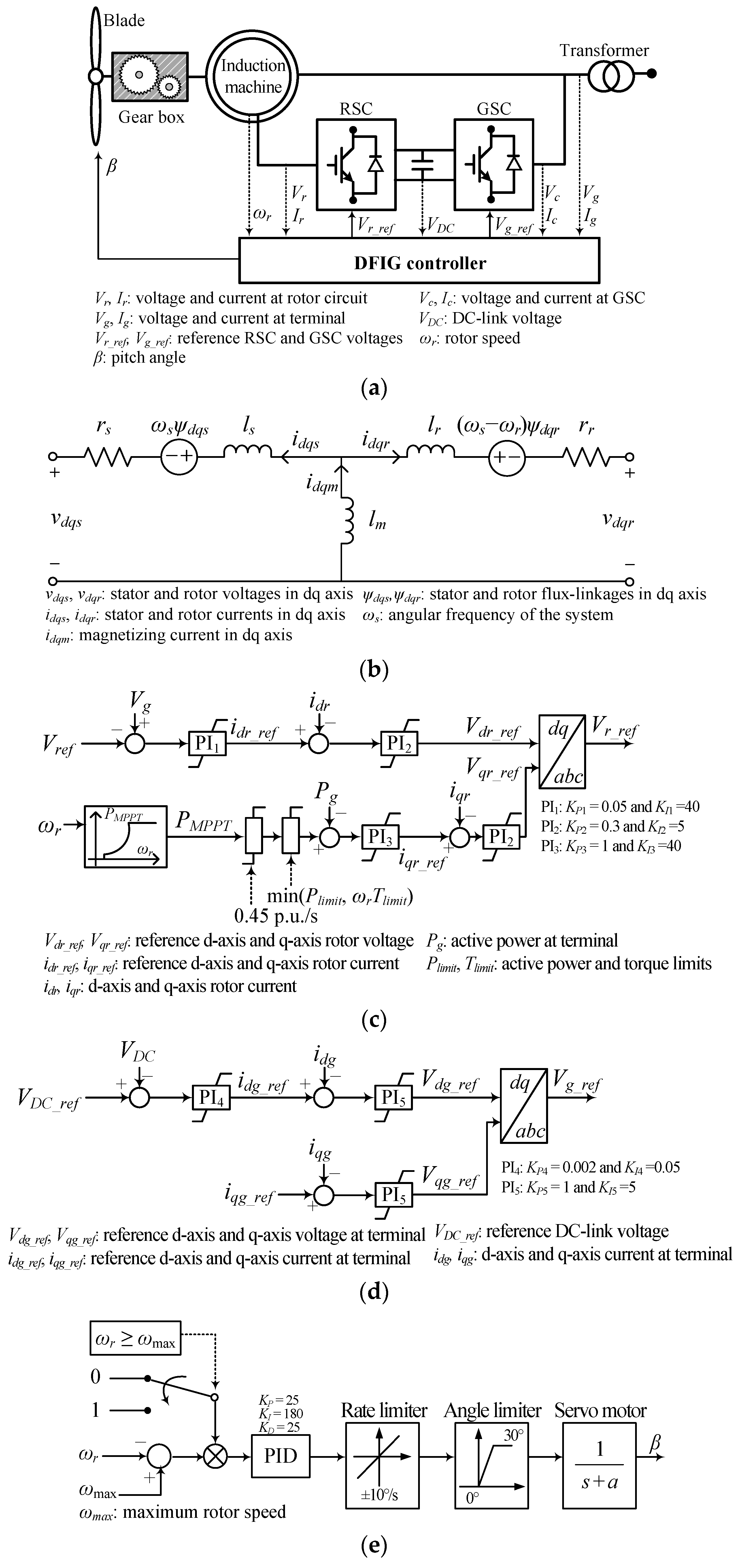
Figure 2.
Input–output power characteristics of a DFIG.

Figure 3.
Conventional power-smoothing scheme in [12].
Figure 3.
Conventional power-smoothing scheme in [12].

Figure 4.
Proposed power-smoothing scheme of a DFIG. (a) Proposed power-smoothing scheme; (b) K (ωr, Δf) represented in the three-dimensional space used in this paper.
Figure 4.
Proposed power-smoothing scheme of a DFIG. (a) Proposed power-smoothing scheme; (b) K (ωr, Δf) represented in the three-dimensional space used in this paper.


Figure 5.
IEEE 14-bus system with two wind power plants (WPPs).
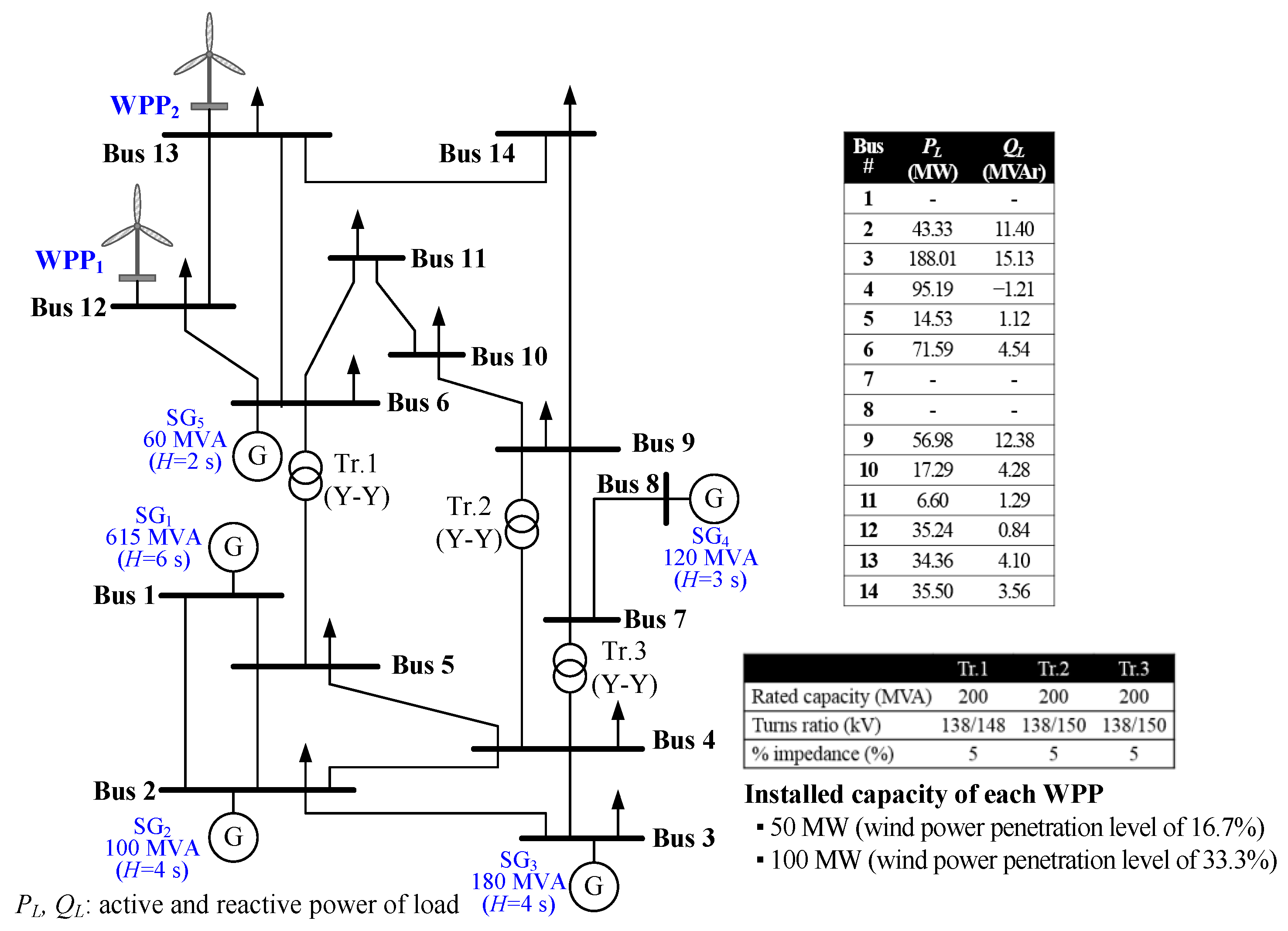
Figure 6.
Input wind speeds for WPPs.

Figure 7.
Results for Case 1. (a) Frequency; (b) Total output power of two WPPs; (c) Output power of WPP1; (d) Output power of WPP2; (e) PMPPT of WPP1; (f) PMPPT of WPP2; (g) ΔP of WPP1; (h) ΔP of WPP2; (i) K (ωr, Δf) of WPP1; (j) K (ωr, Δf) of WPP2; (k) Rotor speed of WPP1; (l) Rotor speed of WPP2; (m) Pitch angle of WPP1.
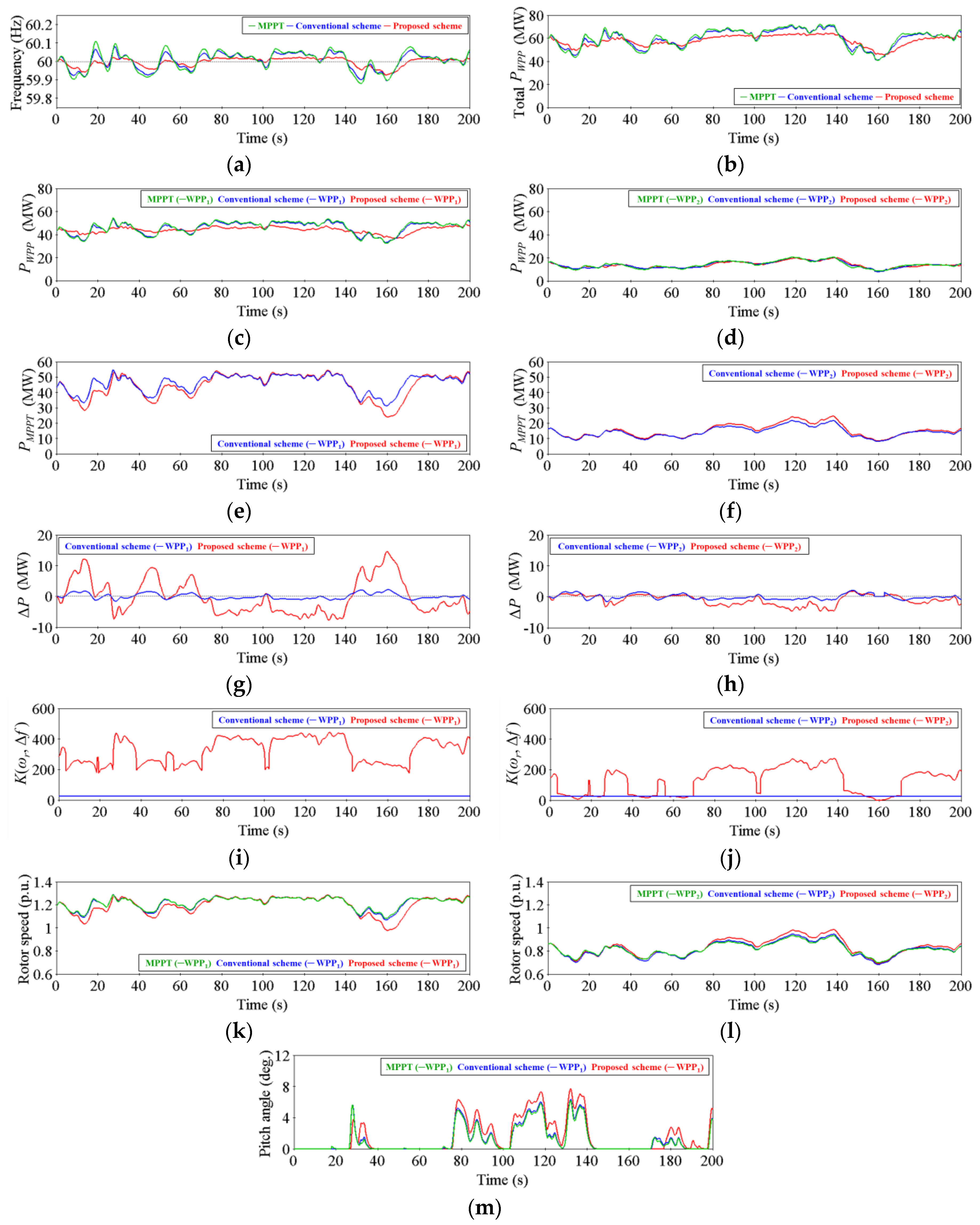
Figure 8.
Results for Case 2. (a) Frequency; (b) Total output power of two WPPs; (c) Output power of WPP1; (d) Output power of WPP2; (e) PMPPT of WPP1; (f) PMPPT of WPP2; (g) ΔP of WPP1; (h) ΔP of WPP2; (i) K (ωr, Δf) of WPP1; (j) K (ωr, Δf) of WPP2; (k) Rotor speed of WPP1; (l) Rotor speed of WPP2; (m) Pitch angle of WPP1.


Table 1.
Results for Case 1. RMS: root mean square.
| Parameter | MPPT Operation | Conventional Scheme | Proposed Scheme |
|---|---|---|---|
| RMS {Δf} (Hz) | 0.051 | 0.043 | 0.024 |
| Δfmax (Hz) | 0.108 | 0.079 | 0.022 |
| Δfmin (Hz) | −0.121 | −0.106 | −0.075 |
| Operating Range of ωr for WPP1 (p.u.) | 0.205 | 0.218 | 0.308 |
| Operating Range of ωr for WPP2 (p.u.) | 0.237 | 0.267 | 0.297 |
Table 2.
Results for Case 2.
| Parameter | MPPT Operation | Conventional Scheme | Proposed Scheme |
|---|---|---|---|
| RMS {Δf} (Hz) | 0.098 | 0.076 | 0.037 |
| Δfmax (Hz) | 0.196 | 0.128 | 0.026 |
| Δfmin (Hz) | −0.235 | −0.191 | −0.113 |
| Operating Range of ωr for WPP1 (p.u.) | 0.209 | 0.235 | 0.385 |
| Operating Range of ωr for WPP2 (p.u.) | 0.245 | 0.285 | 0.320 |
© 2017 by the authors. Licensee MDPI, Basel, Switzerland. This article is an open access article distributed under the terms and conditions of the Creative Commons Attribution (CC BY) license (http://creativecommons.org/licenses/by/4.0/).
Share and Cite
MDPI and ACS Style
Lee, H.; Hwang, M.; Muljadi, E.; Sørensen, P.; Kang, Y.C. Power-Smoothing Scheme of a DFIG Using the Adaptive Gain Depending on the Rotor Speed and Frequency Deviation. Energies 2017, 10, 555. https://doi.org/10.3390/en10040555
AMA Style
Lee H, Hwang M, Muljadi E, Sørensen P, Kang YC. Power-Smoothing Scheme of a DFIG Using the Adaptive Gain Depending on the Rotor Speed and Frequency Deviation. Energies. 2017; 10(4):555. https://doi.org/10.3390/en10040555
Chicago/Turabian StyleLee, Hyewon, Min Hwang, Eduard Muljadi, Poul Sørensen, and Yong Cheol Kang. 2017. "Power-Smoothing Scheme of a DFIG Using the Adaptive Gain Depending on the Rotor Speed and Frequency Deviation" Energies 10, no. 4: 555. https://doi.org/10.3390/en10040555
Note that from the first issue of 2016, this journal uses article numbers instead of page numbers. See further details here.