
Synchronization of Low-Frequency Oscillation in Power Systems

Department of Electrical Engineering, Chonnam National University, Gwangju 500-757, Korea
*
Author to whom correspondence should be addressed.
Energies 2017, 10(4), 558; https://doi.org/10.3390/en10040558
Submission received: 14 January 2017
/
Revised: 22 March 2017
/
Accepted: 14 April 2017
/
Published: 19 April 2017
(This article belongs to the Special Issue Advances in Power System Operations and Planning)
Abstract
:This paper presents the well-documented concept of synchronization of low frequency oscillation occurring in power systems and describes the characteristics of sync occurring in basic electrical circuits. The theory of sync, observed in basic circuits, is extended to analyze the dynamic characteristics of low-frequency oscillation in power systems.
1. Introduction
In a power system, generators and loads are interconnected through a network, and the generators are operated in synchronization at a constant system frequency. If the speed of one generator deviates from the synchronous speed, the power change affects all other generators in the system. When this happens, the system maintains synchronous speed by applying the appropriate control action, such as altering the controllers in the exciter or turbine. However low-frequency oscillation can occur if the setting of the controllers or the state of the network is inadequate. In particular, the high-speed excitation system (used to prevent the loss of synchronizing torque and to improve transient stability) tends to weaken the damping characteristics of low-frequency oscillations [1].
In a power system, low-frequency oscillation is a phenomenon wherein oscillation continues for a relatively long period of time, which can threaten the stability of the system. The dominant oscillation modes occur mainly in a frequency range of 2.0 Hz or less, and especially in the wide-area mode at 1.0 Hz or less. The local mode oscillates several local generators, while the wide-area mode oscillates many generators between areas [2,3,4,5].
Until now, low-frequency analysis in the power system was performed by computing the eigenvalue of the system state matrix. Eigenvalue analysis can accurately calculate the dominant oscillation mode of a large-scale system, and many commercial programs related to eigenvalue analysis and controller design have been developed [6,7,8].
Synchronization (meaning that all machines of a system are operating at the same frequency) is the most important principle for the stable operation of large-scale power systems. Therefore, commercial frequency (50 Hz or 60 Hz) is a topic of considerable interest.
Sync is a phenomenon wherein two events occur simultaneously and continuously for a specific period of time. We also say that sync is a spontaneous order characterized by self-organization and simultaneity [9]. So far, various sync phenomena have been explored involving both living and nonliving objects, including fireflies, brain waves, quantum choruses, asteroid belts, and pacemaker cells, as well as complex network architectures that include regular networks of coupled dynamical systems and small-world networks. These references characterize sync with self-organization and spontaneous order [10,11]. This principle of sync in dynamic systems has recently been expanding into power system analysis [12,13,14]. Dorfler et al. [12] proposed a closed-form condition for synchronization of the fully nonlinear, non-equilibrium, and dynamic network. Dorfler and Bullo [13] described a coupled oscillator approach to the problem of synchronization and transient stability in power networks, and Shim et al. [14] proposed methods to search the synchronization that takes place in power systems.
In this paper, the term ”sync” is differentiated from ”synchronization,” a term that has been widely used in power systems for some time. Synchronization is important for system frequency, but sync of low-frequency oscillation involves not only frequency but also phases.
This paper describes the phenomenon wherein low-frequency oscillations occurring within a power system are synchronized with one another. First, sync is defined, and then the sync phenomenon occurring between voltages and currents in a simple circuit is explained. In addition, the sync of low-frequency oscillation in a power system is analyzed by the synchronization occurring in the parallel circuit. This paper is the first work to analyze the causes of synchronization of low frequency oscillation in a power system using sync of a dynamic system.
The structure of this paper is as follows. Section 2 provides a definition of sync, and gives an example of sync in a basic circuit. Section 3 describes the sync of low-frequency oscillation, and Section 4 discusses the results of the sync in two-area systems and Korea Electric Power Corporation (KEPCO) systems. Finally, Section 5 presents the conclusion.
2. Sync of Basic Circuits
2.1. Definition of Sync
To analyze the sync that occurs in a dynamic system, it is important that the system contains a large number of interconnected oscillators, capable of independent oscillation, that operate at the same amplitude. The system characteristics should depend on the phase [10]. Because a power system has multiple generators connected to the same bus producing similar outputs, they provide the ideal environment for the occurrence of sync.
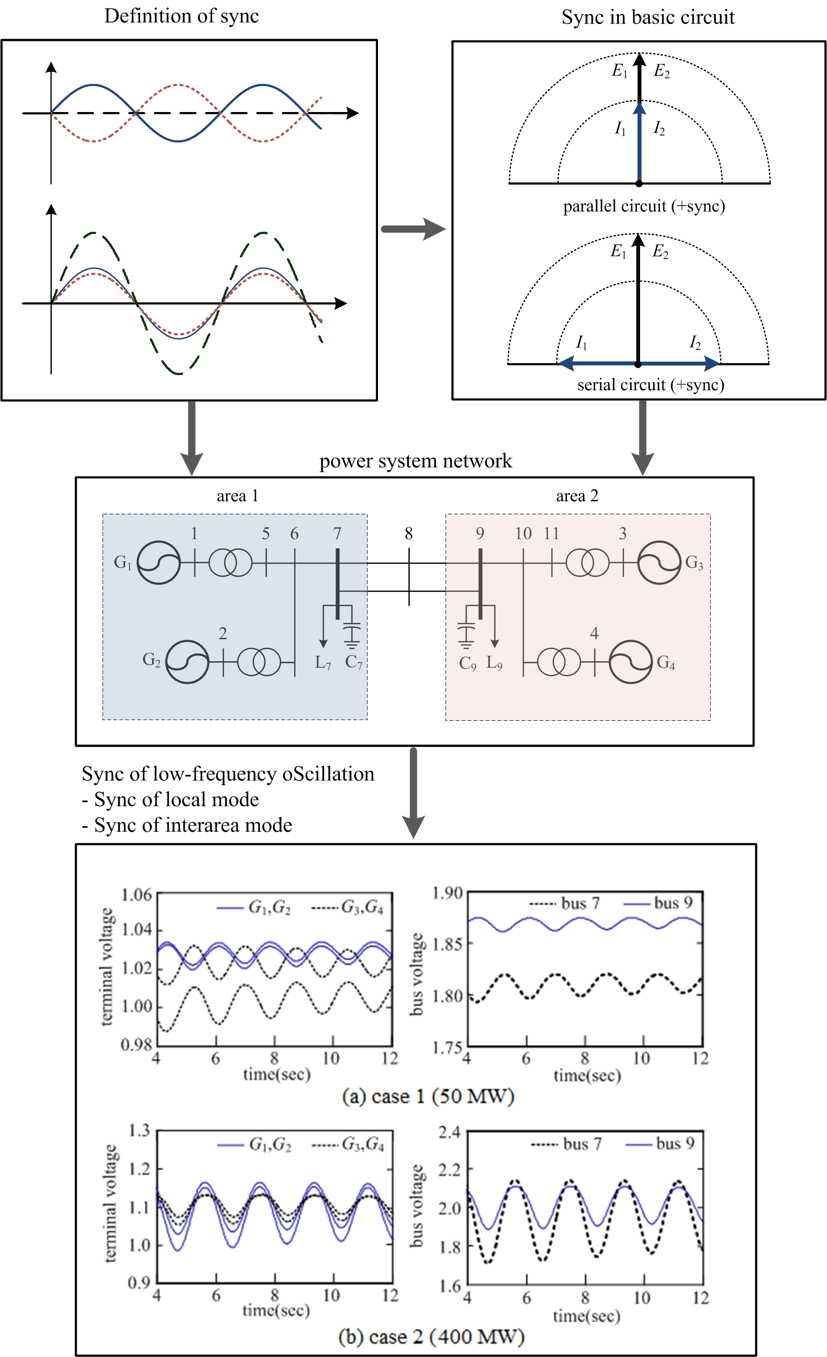
Figure 1 shows sine wave signals. If two signals are identical in amplitude, at a specific time, and their phase difference is 180°, the two signals oscillate in the opposite direction; their sum becomes zero, as in Figure 1a. If the phase difference is 0°, the two signals overlap, combining to create a larger signal, as in Figure 1b. Accordingly, it is called “−sync” if the phase difference between the two signals is 180°, or “+sync” if the difference is 0°. ”Quasi sync” is used to describe situations in which there is neither +sync or −sync.
2.2. Sync in Basic Circuits
Figure 2 shows a simple serial circuit, and a parallel circuit. In order to see the relationship between the phases of two voltage sources and a load current, the figure represents a current source that supplies constant power to the load without being affected by the phase of the voltage source. In Figure 2, it is assumed that current I0, by the current source, is much larger than currents I1 and I2, by the voltage source.
In the circuit, if the load bus voltage has a phase angle of ϕ = 0, and the current source induces a current of I0 = 0[A], the load current can be expressed as a function of the phase angle of the voltage source as follows:
where Ys1 and Ys2 are the composite admittances of the circuit. In the parallel circuit, the composite admittances are as follows:
In the serial circuit, the composite admittances are as follows:
The condition for making load current IL constant for the change of phase angles δ1 and δ2 of the voltage source can be obtained through the partial differentiation of the load current for each phase angle. That is:
If the voltage sources are the same in magnitude, and admittances Y1 and Y2 are identical, Ys1E1/Ys2E2 = 1. In the parallel circuit, the relation between phase angles δ1 and δ2 that satisfy (4) are as follows:
In the serial circuit, the relation between phase angles that satisfy (4) are as follows:
In these conditions, the load current does not flow. If I0 is constant, the load current IL = I0. Conversely, if the maximum load current flows, the voltage phase difference in the parallel circuit is as follows:
The voltage phase difference in the serial circuit is as follows:
Figure 3 shows a vector diagram representing the voltage-current relationship. In the vector diagram of the parallel circuit, if the voltage phase difference is 180°, the load current by the voltage source does not flow, and the phase difference between currents I1 and I2 also becomes 180°. However, if the difference of the voltage phase approaches 0°, the phase difference between currents I1 and I2 also approaches 0°, and the load current by the voltage source becomes the maximum level. The opposite phenomenon occurs in a serial circuit.
In a parallel circuit, if voltage is +sync, the current also becomes +sync and, therefore, the maximum load current flows. However, if the voltage is −sync, currents I1 and I2 become −sync and, therefore, the load current by the voltage source becomes 0. Sync in a serial circuit is opposite to that in a parallel circuit.
Thus, in a parallel circuit, voltages are synchronized to −sync if the load current is small, and to +sync if the load current is large. In a serial circuit, on the other hand, they are synchronized to −sync if the load current is large, and to +sync if the load current is small. Table 1 summarizes the above description of sync in parallel and serial circuits.
3. Sync of Low-Frequency Oscillation
Low-frequency oscillations in the power system usually contain multiple modes, which are affected by generator inertia, transmission line impedance, and governor and excitation control. This oscillation is a phenomenon in which generators oscillate at a 0.2–2.0 Hz frequency, and is divided into local mode and interarea mode [1,3]. In the local mode, some local generators oscillate at a specific frequency, and in the interarea mode, generators oscillate in a group.
Sync occurring in a large-scale dynamic system is both an extensive and simultaneous phenomenon. Generator output is changed by disturbances such as load change, but constant power is supplied to the load through an appropriate control operation. In such a situation, if the system has a vulnerable damping characteristic, low-frequency oscillation continues, and oscillations are synchronized with one another.
3.1. Sync of Local Mode
The adjacent generators in the same area are connected strongly from an electrical standpoint. The oscillations between these generators tend to oscillate at the same frequency, which are relatively higher. A mode in which only some local generators participate in oscillation is called a “local mode” [3,4].
Figure 4 shows generator groups interconnected with other generator groups through a network. In such a system, sync among the generators inside the area occurs simultaneously with that among the areas themselves.
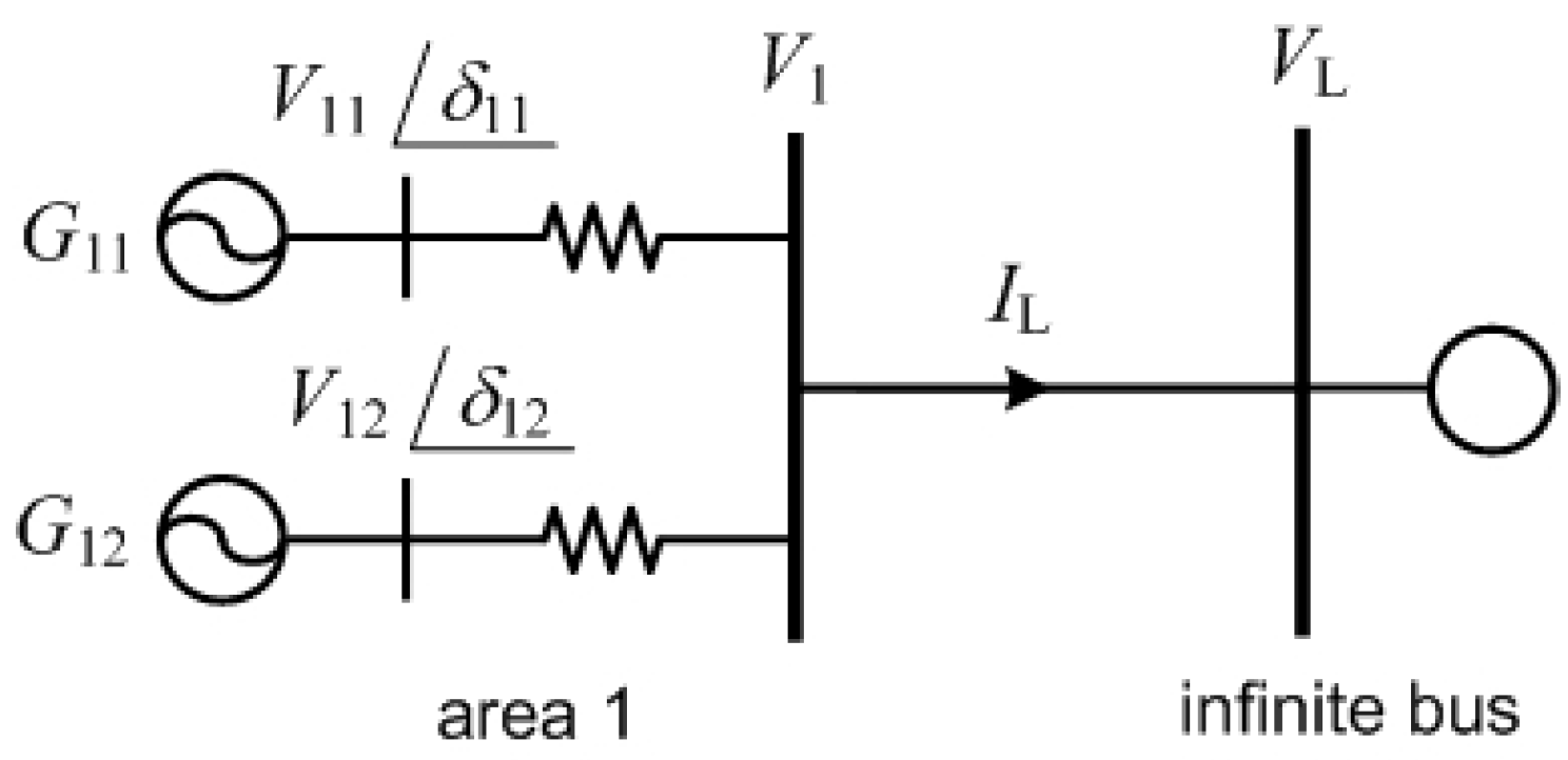
Sync between generators in Area 1 is determined by load condition. During normal parallel operation, the overall system load is always larger than the output of the local generator group. If the output sum of the generators in Area 1 is PG1, and the total load is PL, the following equation is established:
Under this condition, the overall network (except Area 1) is equivalent to an infinite bus, as shown in Figure 5. Therefore, it can be assumed that the load is very large in the parallel circuit shown in Figure 2. Accordingly, a large current flows from Area 1 to the network. The voltage phase difference of Area 1 satisfies the following:
where δ11 and δ12 are the phase angles of generator terminal voltage of Area 1.
In the vector diagram of a parallel circuit in Figure 3, if a large load current flows, the phase difference of the generator terminal voltages becomes small and, therefore, generators within the local group are synchronized to +sync with one another. Thus, generators in a local bus connected to a large-scale network are synchronized to +sync with one another. This phenomenon is the same as the concept of local mode in a linear analysis.
3.2. Sync of Interarea Mode
Generators in the same local area can also oscillate against generators in the other local areas. This is called “interarea oscillation” and the oscillation mode is called “interarea modes”. If generator groups in different areas are connected through long-distance transmission lines, the generator groups between areas are weakly connected from an electrical standpoint. For interarea modes, the generators in a local area swing together against other local areas at a frequency of 0.2–1.0 Hz [3,4].
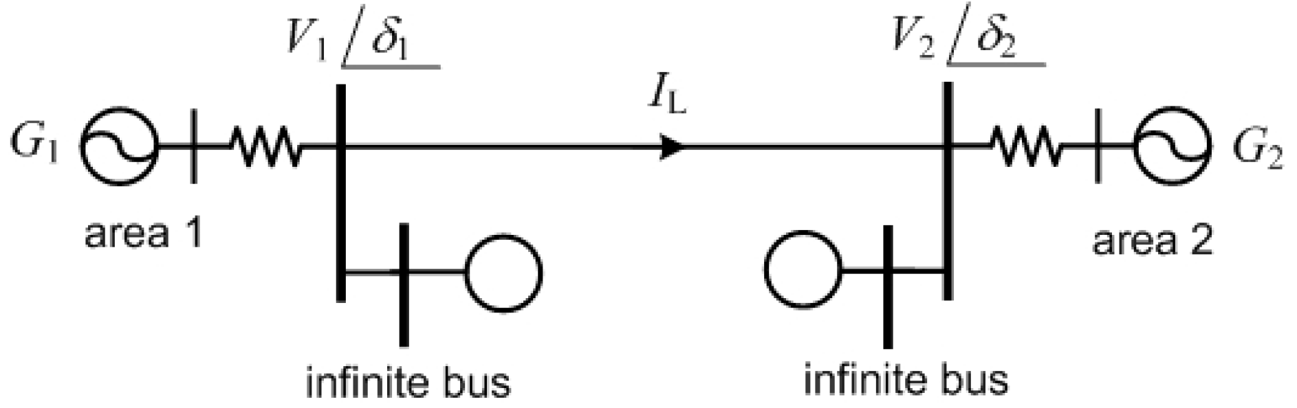
If local generators are synchronized to +sync, the generator group of that local area can be converted to an OMIB (one machine infinite bus) system. If this occurs, areas 1 and 2 can be considered to be connected to a parallel circuit, as shown in Figure 6. Therefore, the sync of interarea modes can deal with the sync of a parallel circuit.
If Areas 1 and 2 are weakly connected, it can be assumed that there is a small load between areas. Therefore, the load is small in the parallel circuit shown in Figure 2, and a small current flows from Area 1 to Area 2. The voltage phase difference between Area 1 and Area 2 satisfies the following:
where δ1 and δ2 are the phase angles of bus voltage.
In the vector diagram of a parallel circuit, if a small load current flows, the phase difference of the generator terminal voltages becomes large. Therefore, the generators of Area 1 and Area 2 are synchronized to −sync with each other. This is similar to the concept of interarea mode in a linear analysis.
The sync of interarea modes depends on the load distribution and network configuration. If the load near the generator group is small, the power flow from the local area to the network is large. Conversely, if the load of a local area is large, the power flow from the local area to the network is small. The small power flow means that the generator groups between areas are weakly connected to the network.
In Figure 6, if the small power flows from areas to the network, Area 1 and Area 2 are weakly connected to the network. Therefore, the generator groups are synchronized to −sync with each other. This is similar to the sync of the parallel circuit flowing small load current.
However, if the difference of the generation or the load between areas is large, the sync of the interarea mode may vary to quasi sync, due to an unbalanced power flow. This does not satisfy the sync condition that the magnitude of the oscillators should be the same. If the sync of the balance state (−sync) is changed to the +sync or quasi sync, the system stability margin is reduced. Various controllers operate to maintain stable and optimal operation in power systems. In this process, generators are self-organized and synchronized to each other.
3.3. Sync in Wide Area System Operation
When low-frequency oscillation occurs in a power system, local generators are synchronized to +sync with each other. Because the overall system load is much larger than the local area load in normal power systems, the excess power flows from the local area to the network, and +sync occurs. This sync of a local mode is simple.
However, the sync of an interarea mode is not simple. In a typical power system, the generator and the load are distributed over a wide area. The sync of an interarea mode can occur in various forms, as a network configuration. When this happens, both the load and the generator participate in the oscillation. Therefore, the load with the oscillating generator can be treated as a group. If the loads of areas 1 and 2 are large, as shown in Figure 6, the small power and current flow through the network. Therefore, the interarea mode is synchronized to –sync in typical power systems.
The network configuration can be changed by the system failure, or the insertion of a large load and generation. This change can be varied with the sync of interarea mode. That is, −sync is changed to +sync or quasi sync. For the stable operation of the wide area power system, with the large damping factor of the low-frequency oscillation mode, the local mode must remain a +sync, and the interarea mode must remain a –sync. The sync of the complex system may be the basis of the stable operation of the large-scale power systems.
4. Numerical Examples
4.1. Two-Area System
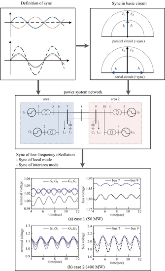
A two-area system has been used to verify the sync of low-frequency oscillations. Figure 7 shows a two-area system [1,2]. The system parameters were identical to those in [2]. Dynamic simulations were performed for two load conditions, in order to examine the sync of low-frequency oscillations. In Case 1, a small power flow exists from Area 1 to Area 2, due to the presence of equal loads in each area. In Case 2, with a load in Area 2 larger than the generation, a large power flow exists in the tie line. The power flows in the tie lines for Case 1 and Case 2 are 50 MW and 400 MW, respectively.
The test results for each case are shown in Figure 8. Approximately 4.0 s after fault clearing, the generators G1 and G2 were synchronized to +sync and G3 and G4 to +sync in each case. Since the overall load is greater than the generation of each local area, a large current flows from the local area to the network, and the generators in a local area are synchronized to +sync with each other, as shown in Table 1. Figure 8a shows Case 1, in which generator groups in Areas 1 and 2 are oscillating in –sync. Since the power flow from Area 1 to Area 2 is small, the voltages are synchronized to –sync.
Figure 8b shows Case 2, in which local area generators are oscillating in +sync, as in Case 1. However, with a large power flow, the generators of Area 2 dominate the wide-area oscillation. In this case, the generators of a specific local area dominate the wide-area oscillation, and this kind of system can easily become unstable, even with a small disturbance.
The two-area systems described above have a symmetric network structure. Therefore, two-area systems are an ideal system wherein sync of low-frequency oscillation can occur, as shown in Figure 8. However, if the operating conditions of a system like Case 1 are changed to those of Case 2, the sync of the system also changes, and sync breakdown can occur.
4.2. KEPCO System
The sync of low-frequency oscillation was examined in the KEPCO system, consisting of 281 generators and 1584 bus bars [15]. A simplified diagram of the KEPCO system and generator groups are shown in Figure 9. In a KEPCO system, the loads are concentrated in the Gyeongin and Gyeongnam areas.
Numerous oscillation modes were calculated in the linear analysis of the KEPCO system. Dominant oscillation modes are represented in Table 2. “real” and “imag” in Table 2 mean the real and imaginary parts of modes, respectively; “damping” and “freq”, refer to the damping constant and frequency of modes, respectively.
The dominant mode with the worst damping characteristics was the 0.626 Hz frequency mode. The mode shapes for dominant oscillation modes are calculated, with the results shown in Figure 10. It is shown that the mode shapes are distributed with the same phases in the same areas, and the phase between the areas is distributed 180 degrees out of phase.
Therefore, the mode with 0.626 Hz frequency can be considered as an interarea mode, with the southeast area generators, including the Gori area (GR: Gori; US: Ulsan; and WS: Wolseong), and the northwest area generators, including the Seoincheon area (SIC: Seoincheon; and IC: Incheon), mutually oscillating.
The main load on the KEPCO system is in the Gyeongin area, including Seoul. In most cases, the power generated in the southern area is transmitted to the Gyeongin area. As shown in Figure 9, there is a large load near the Seoincheon area, and a large load near the Gori area. Therefore, the power flowing from the southeast area to the northwest area is not large, and the two areas are connected weakly.
When a large load current flows in a parallel circuit, it is synchronized to + sync. Therefore, local generators are synchronized to +sync because there is a large current flow from the local area to the network. The southeast area generators, centering on the Gori area, were synchronized to +sync and the northwest area generators to +sync.
When a small load current flows in a parallel circuit, it is synchronized with −sync. Since the southeast and northwest areas are weakly connected, a small current flows from the southeast area to the northwest. So, the southeast area generator group and the northwest area generator group are oscillating in –sync, as shown Figure 10.
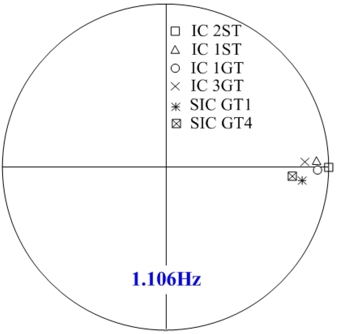
The mode shapes for the 1.106 Hz frequency mode were calculated, with the results shown in Figure 11. As shown, the mode shapes are distributed with the same phases. Therefore, the mode can be considered as a local mode of the northwest area generators, including the Seoincheon area.
The Seoincheon area is located near the Gyeongin area with the large load. A large amount of power is transmitted from the Seoincheon area to the Gyeongin area. When a large load current flows in a parallel circuit, it is synchronized to +sync. Therefore, local generators are synchronized to +sync because there is a large current flow from the local area to the network. The northwest area generators, centering on the Seoincheon area, were synchronized to +sync.
If a system structure in operation at −sync is changed, and sync is weakened or disappears, the wide-area oscillation increases and even a small disturbance can lead to the system becoming unstable. This can be seen in the example of the two-area system described above. Therefore, the system should be operated in a way that +sync between a local area and another area does not occur.
The real power system is not symmetrical as in the case of the two-area system. Additionally, when oscillation occurs, various modes are synthesized. The oscillations of the local generators are synchronized to +sync exactly. In many cases, however, when interarea oscillations occur, the voltage and current are synchronized in quasi sync. This is because the network is not symmetrical and the generator is affected by other modes.
4.3. Discussion
This paper shows that low-frequency oscillations in the power system can be analyzed from the synchronization of simple parallel circuits. The results can be summarized as follows:
The local mode, which only oscillates several local generators, is synchronized with +sync. Because a power system is connected in parallel, and the overall system load is always larger than the local generation, a large current flows to the network and the local generators are in + sync.
The interarea mode, which is characterized by groups of coherent generators swinging against each other, is synchronized with −sync. If the amount of power transfer on the tie-lines between the areas is small, the network is weakly connected and a small current flows to the network; the generator groups between the areas are in −sync.
When the system is operating reliably with −sync, if the synchronization becomes weakened or disappears, a sync breakdown phenomenon can occur. This can make a particular local generator group dominate the overall system oscillation, which can make even a small disturbance affect the whole system to be unstable. When such a global oscillation occurs, adaptive wide-area damping control can be effective [16]. Therefore, when system oscillation is analyzed by the sync of low-frequency oscillations, it is possible to determine the stability margin of the overall system.
5. Conclusions
This paper described the phenomenon wherein low-frequency oscillations are synchronized with one another in a power system. The sync of low-frequency oscillation was defined, and sync between voltages and currents in basic electric circuits was derived and proved. In addition, the sync of the power system was analyzed by extending the sync of the basic electrical circuit.
Sync concepts proposed in this paper were applied to two-area systems and the KEPCO systems, and it was confirmed that the synchronization phenomenon can be usefully applied to the power system. The sync of low-frequency oscillation can be applied to the synchro-phasor and it can be used in real-time system operation.
Author Contributions
Kwan-Shik Shim prepared the manuscript and completed the theory and simulations. Joon-Ho Choi supervised the study and discussed the results. Seon-Ju Ahn commented on the manuscript. All of the authors read and approved the final manuscript.
Conflicts of Interest
The authors declare no conflict of interest.
References
- Kundur, P. Power System Stability and Control; McGraw-Hill, Inc.: New York, NY, USA, 1994. [Google Scholar]
- Klein, M.; Rogers, G.; Kundur, P. A fundamental study of inter-area oscillations in power systems. IEEE Trans. Power Syst. 1991, 6, 914–921. [Google Scholar] [CrossRef]
- Kundur, P.; Paserba, J.; Ajjarapu, V.; Andersson, G.; Bose, A.; Canizares, C.; Hatziargyriou, N.; Hill, D.; Stankovic, A.; Taylor, C.; et al. Definition and classification of power system stability. IEEE Trans. Power Syst. 2004, 19, 1387–1401. [Google Scholar]
- Rogers, G. Power System Oscillations; Kluwer Academic Publishers: Dordrecht, The Netherlands, 2000. [Google Scholar]
- Machowski, J.; Bialek, J.W.; Bumby, J.R. Power System Dynamics: Stability and Control; John Wiley & Sons, Ltd.: West Sussex, UK, 2008. [Google Scholar]
- Wang, L.; Semlyen, A. Application of sparse eigenvalue techniques to the small signal analysis of large power systems. IEEE Trans. Power Syst. 1990, 4, 635–642. [Google Scholar] [CrossRef]
- Small Signal Analysis Tool (SSAT). Available online: http://www.dsatools.com/ssat/ (accessed on 25 May 2014).
- Electric Power Research Institute. Small Signal Stability Analysis Program Package ver.3.0; Final Report, TR-101850; EPRI: Palo Alto, CA, USA, 1993. [Google Scholar]
- Strogatz, S.H. Exploring complex networks. Nature 2001, 410, 268–276. [Google Scholar] [CrossRef] [PubMed]
- Strogatz, S.H. Sync: The Emerging Science of Spontaneous Order; Hyperion Books: New York, NY, USA, 2003. [Google Scholar]
- Earl, M.G.; Strogatz, S.H. Synchronization in oscillator networks with delayed coupling: A stability criterion. Phys. Rev. 2003, 67, 036204. [Google Scholar] [CrossRef] [PubMed]
- Dorfler, F.; Chertkov, M.; Bullo, F. Synchronization in complex oscillator networks and smart grids. Proc. Natl. Acad. Sci. USA 2013, 110, 2005–2010. [Google Scholar] [CrossRef] [PubMed]
- Dorfler, F.; Bullo, F. Synchronization and transient stability in power networks and nonuniform Kuramoto oscillators. SIAM J. Control Optim. 2012, 50, 1616–1642. [Google Scholar] [CrossRef]
- Shim, K.S.; Nam, H.K.; Lim, Y.C. Use of Prony analysis to extract sync information of low-frequency oscillation from measured data. Eur. Trans. Electr. Power 2011, 21, 1746–1762. [Google Scholar] [CrossRef]
- Shim, K.S.; Kim, S.T.; Nam, H.K.; Choi, J.H. Initial results of low-frequency oscillation analysis based on PMU in KEPCO system. Trans. Korean Inst. Electr. Eng. 2014, 63, 1–9. [Google Scholar] [CrossRef]
- Cai, G.; Yang, D.; Liu, C. Adaptive wide-Area damping control scheme for smart grids with consideration of signal time delay. Energies 2013, 6, 4841–4858. [Google Scholar] [CrossRef]
Figure 1.
Sync of signal. (a) –sync; and (b) +sync.
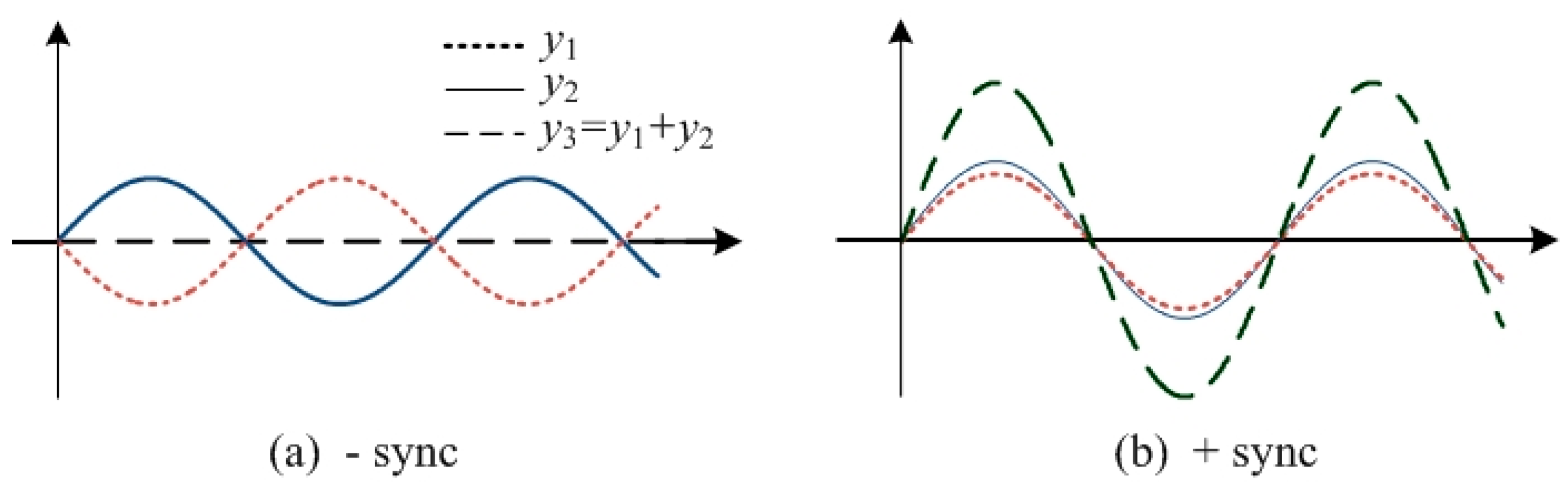
Figure 2.
Serial and parallel circuits with two voltage and current sources. (a) Parallel circuit; and (b) serial circuit.
Figure 2.
Serial and parallel circuits with two voltage and current sources. (a) Parallel circuit; and (b) serial circuit.
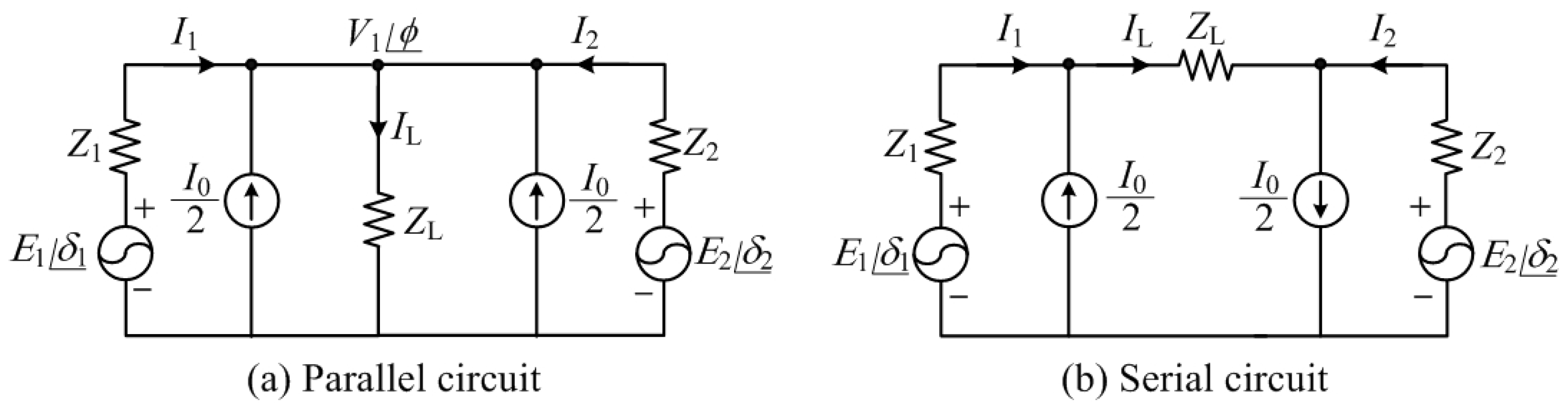
Figure 3.
Voltage-current phase relationship of serial and parallel circuit. (a) +Sync in parallel circuit (large current); (b) −sync in parallel circuit (small current); (c) +sync in serial circuit (small current); and (d) −sync in parallel circuit (large current).
Figure 3.
Voltage-current phase relationship of serial and parallel circuit. (a) +Sync in parallel circuit (large current); (b) −sync in parallel circuit (small current); (c) +sync in serial circuit (small current); and (d) −sync in parallel circuit (large current).
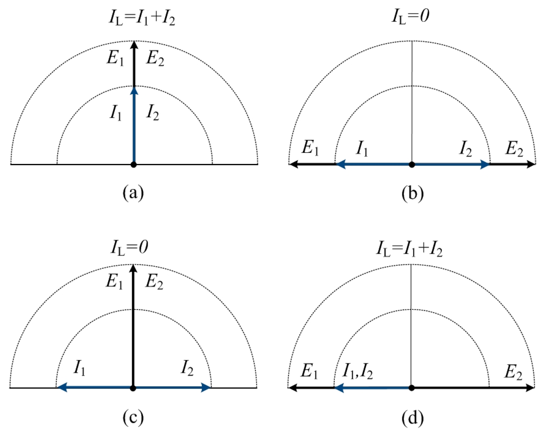
Figure 4.
Local and wide area network.
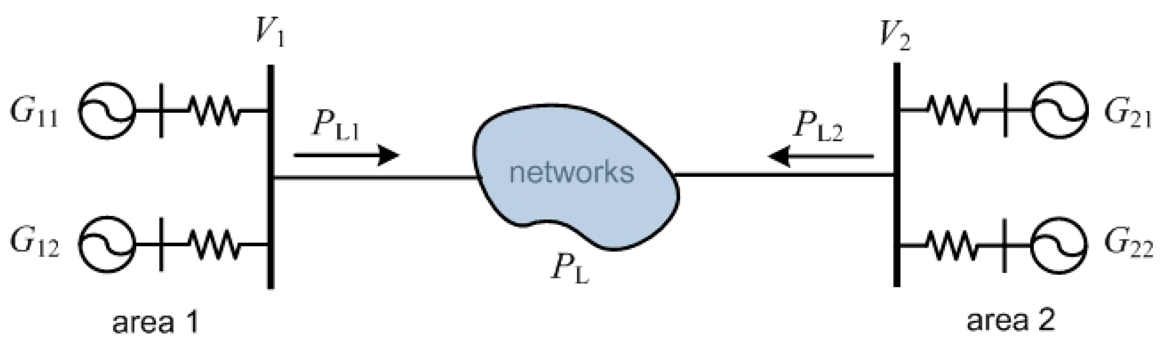
Figure 5.
Equivalent system with infinite bus.

Figure 6.
Equivalent system with infinite bus.

Figure 7.
Two-area systems (Case 1: 50 MW; and Case 2: 400 MW).
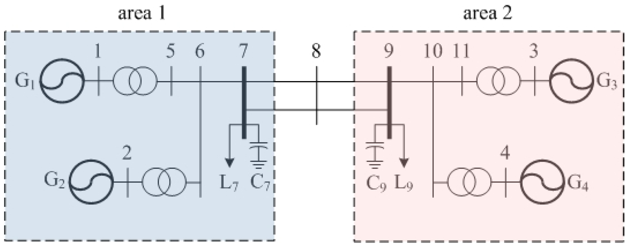
Figure 8.
Sync of generator and bus voltage in two-area system: (a) Case 1 (power flows: 50 MW); and (b) Case 2 (power flows: 400 MW).
Figure 8.
Sync of generator and bus voltage in two-area system: (a) Case 1 (power flows: 50 MW); and (b) Case 2 (power flows: 400 MW).
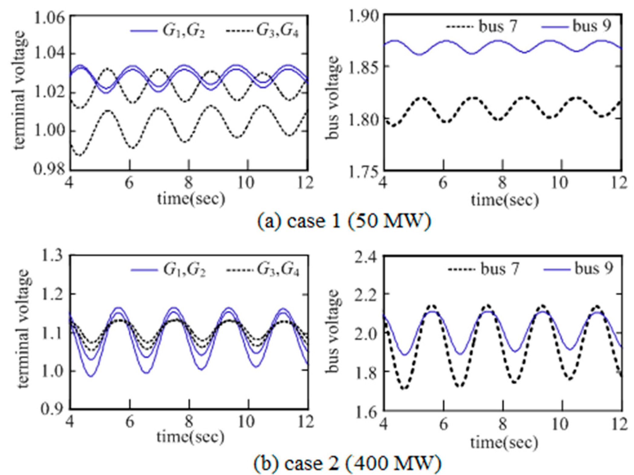
Figure 9.
Simplified diagram of the Korea Electric Power Corporation (KEPCO) system.
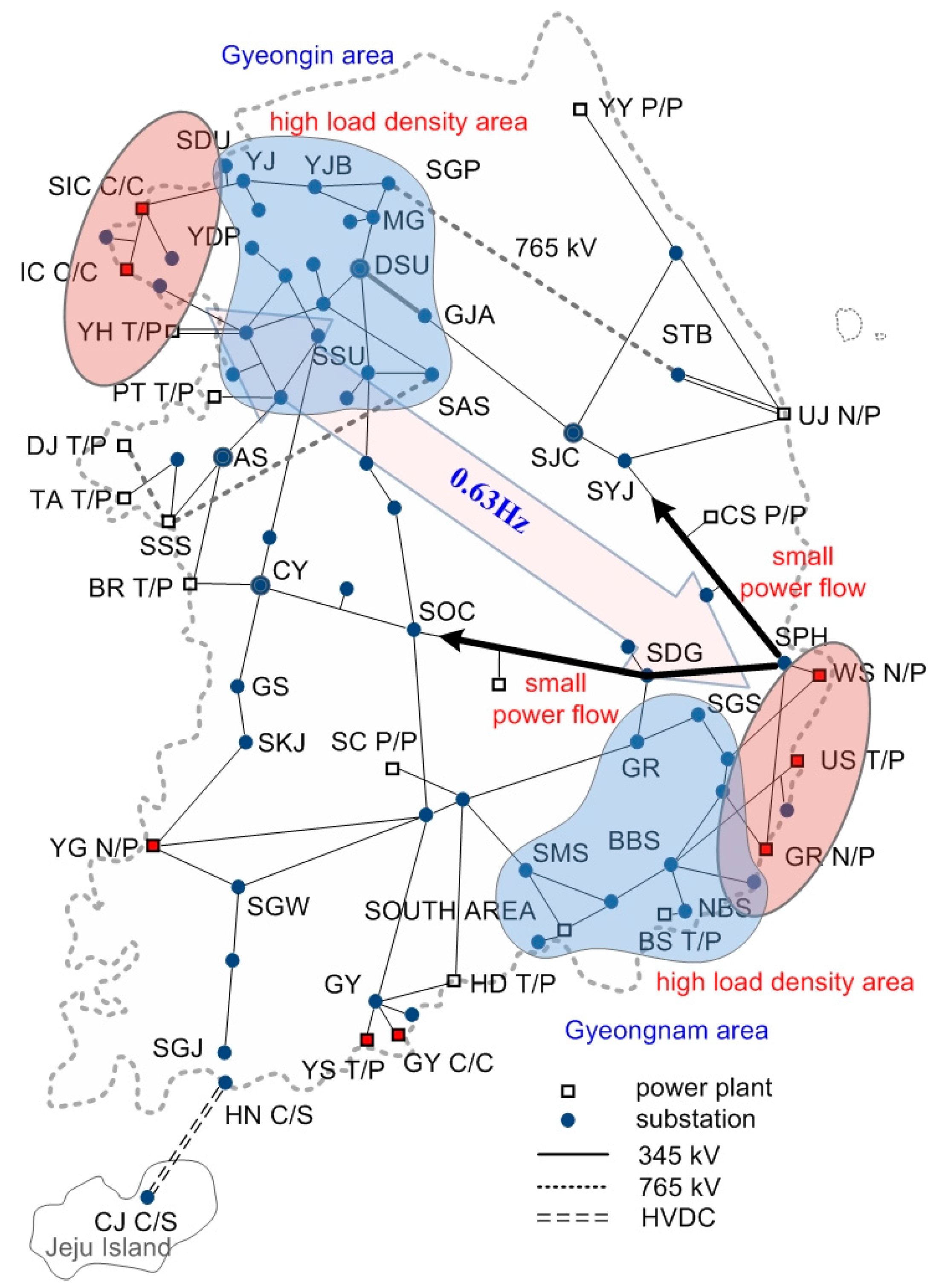
Figure 10.
Sync of the interarea mode. GR: Gori area generators; US: Ulsan area generators; IC: Incheon area generators; and SIC: Seoincheon area generators.
Figure 10.
Sync of the interarea mode. GR: Gori area generators; US: Ulsan area generators; IC: Incheon area generators; and SIC: Seoincheon area generators.
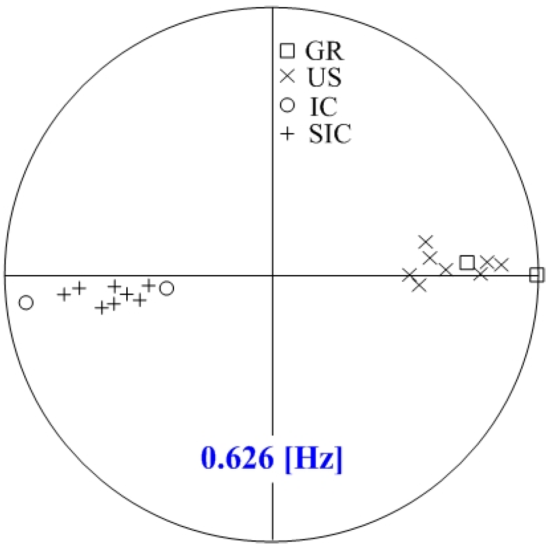
Figure 11.
Sync of the local mode. IC 1ST: IC steam turbine unit 1; IC 2ST: IC steam turbine unit 2; IC 1GT: IC gas turbine unit 1; IC 3GT: IC gas turbine unit 3; SIC GT1: SIC gas turbine unit 1; and SIC GT4: SIC gas turbine unit 4.
Figure 11.
Sync of the local mode. IC 1ST: IC steam turbine unit 1; IC 2ST: IC steam turbine unit 2; IC 1GT: IC gas turbine unit 1; IC 3GT: IC gas turbine unit 3; SIC GT1: SIC gas turbine unit 1; and SIC GT4: SIC gas turbine unit 4.


Table 1.
Sync in basic circuits.
| Circuit | Voltage | Load Current | Voltage Phase Difference | |
|---|---|---|---|---|
| Parallel | −sync | –sync | small | 180° |
| +sync | +sync | large | 0° | |
| Serial | –sync | +sync | large | 0° |
| +sync | –sync | small | 180° | |
Table 2.
Oscillation modes of KEPCO system.
| Modeno | Mode | Freq (Hz) | Damping (%) | Dominant State | |
|---|---|---|---|---|---|
| Real | Imag | ||||
| 1 | −0.2236 | 3.9364 | 0.6265 | 5.67 | 29252 : GR 4G 22.0 : |
| 2 | −0.5509 | 6.9511 | 1.1063 | 7.90 | 23436 : IC 2ST 16.0 : |
| 3 | −0.5278 | 6.2897 | 1.0010 | 8.36 | 23433 : IC 1ST 16.0 : |
| 4 | −0.5029 | 5.9437 | 0.9460 | 8.43 | 23433 : IC 1ST 16.0 : |
| 5 | −0.5575 | 5.8178 | 0.9259 | 9.54 | 27155 : YG 5G 22.0 : |
© 2017 by the authors. Licensee MDPI, Basel, Switzerland. This article is an open access article distributed under the terms and conditions of the Creative Commons Attribution (CC BY) license (http://creativecommons.org/licenses/by/4.0/).
Share and Cite
MDPI and ACS Style
Shim, K.-S.; Ahn, S.-J.; Choi, J.-H. Synchronization of Low-Frequency Oscillation in Power Systems. Energies 2017, 10, 558. https://doi.org/10.3390/en10040558
AMA Style
Shim K-S, Ahn S-J, Choi J-H. Synchronization of Low-Frequency Oscillation in Power Systems. Energies. 2017; 10(4):558. https://doi.org/10.3390/en10040558
Chicago/Turabian StyleShim, Kwan-Shik, Seon-Ju Ahn, and Joon-Ho Choi. 2017. "Synchronization of Low-Frequency Oscillation in Power Systems" Energies 10, no. 4: 558. https://doi.org/10.3390/en10040558
Note that from the first issue of 2016, this journal uses article numbers instead of page numbers. See further details here.