
Influences of Winding MMF Harmonics on Torque Characteristics in Surface-Mounted Permanent Magnet Vernier Machines


Mechatronics System Research Laboratory, Electrical Engineering Department, Dong-A University, Busan 52121, Korea
*
Author to whom correspondence should be addressed.
Energies 2017, 10(4), 580; https://doi.org/10.3390/en10040580
Submission received: 8 February 2017
/
Revised: 7 April 2017
/
Accepted: 20 April 2017
/
Published: 23 April 2017
(This article belongs to the Section D: Energy Storage and Application)
Abstract
:This paper presents the influences of winding magneto-motive force (MMF) harmonics on the torque characteristics in surface-mounted permanent magnet vernier (SPMV) machines. Based on the magnetic gearing effects, the armature magnetic field of the SPMV machines is modulated by flux modulation poles (FMPs). In the modulated magnetic field, a working harmonic which corresponds to the number of the rotor pole pairs generates torque. Unlike regular PM machines, the winding MMF harmonics in the SPMV machines can produce the working harmonic by adjusting the FMP shapes. In order to investigate the effects of the winding MMF harmonics, the operating principle of the SPMV machines is elaborated by an analytical method using the winding MMF distribution and air-gap permeance function. After that, the design method of the FMP shapes that can improve the output torque by using the winding MMF harmonics is proposed. For the SPMV machine having 6 slots and 24 FMPs, the effects of the winding MMF harmonics and the validity of the proposed design method are confirmed by the finite element analysis method. It is shown that the proposed design method can improve the performances of the SPMV machine in terms of the torque density, induced electromagnetic force, and efficiency.
1. Introduction
In many industrial applications which require high torque capability, permanent magnet vernier (PMV) machines have attracted much attention due to their high torque density and high efficiency [1,2,3,4,5]. In the PMV machines, the low spatial harmonic of the winding magneto-motive force (MMF) distribution in the air-gap is modulated into the higher spatial harmonic by flux modulation poles (FMPs), which are formed on the stator. Then, the resulting higher spatial harmonic generates torque by interacting with the rotor PM magnetic field of the same spatial order. The phenomenon which is called the “magnetic gearing effects” facilitates the high torque capability of the PMV machine. Hence, based on the principle of the magnetic field modulation, many topologies of the PMV machines have been investigated in order to improve their torque density and power factor [6,7,8,9,10,11].
In surface-mounted PM (SPM) machines, due to the stator slotting, the air-gap permeance function includes the harmonic of the spatial order corresponding to the number of the slots [12]. The slot harmonics are known to affect the cogging torque and iron loss [13,14]. However, the effect of the stator slotting cannot improve the magnitude of the generated torque in the SPM machines. On the contrary, the surface-mounted PMV (SPMV) machines employ the harmonics of the air-gap permeance function for their high torque capability. In the SPMV machines, the air-gap permeance function is determined by the geometry of the FMPs and contains the spatial harmonic corresponding to the number of the FMPs. Based on the magnetic gearing effects, the fundamental wave of the winding MMF distribution creates the higher spatial harmonic of the air-gap flux density distribution by interacting with the harmonics of the air-gap permeance function. In order to generate useful torque on the rotor by synchronizing with the armature magnetic field, the number of the rotor pole pairs should be equal to the spatial order of the modulated harmonic of the winding MMF. In the same manner, the MMF distribution by the rotor PMs is also modulated by the air-gap permeance function into the magnetic field component which corresponds to the fundamental wave of the winding MMF distribution. Thus, the magnetic field by the rotor PMs induces the induced electromotive force (EMF) with the rotation of the rotor at a no-load condition.
For the SPMV machine, the equations of the output torque and back EMF are developed by using the analytical method [11,15,16]. Moreover, the effects of the winding configurations on the output torque are investigated [17]. However, the previous studies focused on the characteristics of the magnetic field modulation that is caused by the fundamental wave of the winding MMF distribution. Thus, the harmonic components of the winding MMF distribution were neglected in the analytical equations. Based on the magnetic gearing effects, the winding MMF harmonics are also varied by the harmonics of the air-gap permeance function. In addition, each harmonic of the winding MMF distribution can contribute to increasing the output torque by adjusting the harmonic characteristics of the air-gap permeance function. The aims of this paper are to show that the winding MMF harmonics have an influence on the torque characteristics of the SPMV machine by adjusting the FMP shape, and propose the design method of the FMP shape for improving the torque capability. In Section 2, the operating principle of the magnetic gear and SPMV machine is introduced. Compared with magnetic gears, the effects of the winding MMF harmonics on the radial flux density distribution in the air-gap are illustrated. In the radial flux density distribution produced by the armature windings, a modulated harmonic having the highest amplitude is selected as a working harmonic. In the SPMV machine, the working harmonic means a spatial harmonic of the magnetic flux distribution in the air-gap that is created by the armature windings and affects the output torque. Hence, the working harmonic generates the output torque by interacting with the magnetic field of the same spatial order created by the rotor PMs. In addition, it is explained that the winding MMF harmonics can affect the working harmonic and output torque by adjusting the harmonic characteristics of the air-gap permeance function. In Section 3, for the SPMV machine having 6 slots and 24 FMPs, the winding MMF distribution, the air-gap permeance function, and the radial flux density distribution by the armature windings are calculated by using the analytical and finite element analysis (FEA) methods. In addition, the effects of the winding MMF harmonic on the working harmonic are investigated. Based on the analysis results and the operation principle, the FMP shapes are designed to improve the working harmonic by using the winding MMF harmonics. In Section 4, using the FEA method, the performance of the SPMV machines such as the output torque, induced EMF, and efficiency are analyzed according to the FMP shapes which are designed by the proposed method in this paper. For a fair comparison, the same structure of the rotor including the rotor PMs is applied for the analysis models. It can be found that the output torque of the SPMV machine is improved with the increase of the working harmonic of the armature magnetic field in the air-gap which results from the interaction between the winding MMF harmonics and air-gap permeance harmonics. In addition, the proposed design method can improve the performances of the SPMV machine in terms of the torque density, induced EMF, and efficiency.
2. Operating Principle
2.1. Magnetic Gears
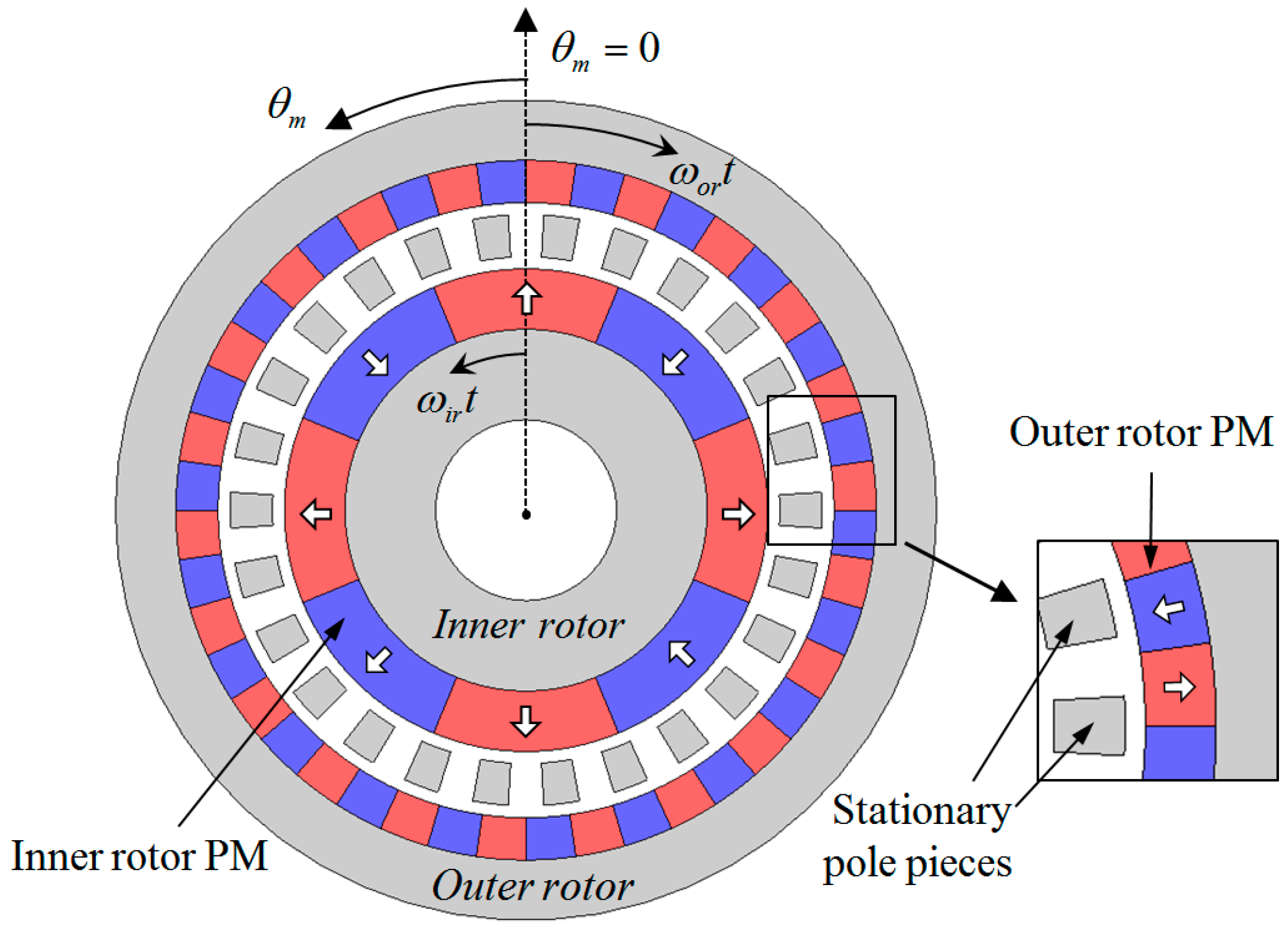
Figure 1 shows a general structure of the magnetic gears. It consists of the inner and outer rotors having surface-mounted PMs, and the stationary pole pieces. When only considering the magnetic field by the inner rotor PMs, the radial components of the flux density distribution in the outer air-gap can be written in the following form [18].
In Equation (1), the first term indicates the radial flux density distribution without the stationary pole pieces which is produced by the harmonic components of the inner rotor PM MMF. The other term describes the flux modulating function that is actually the air-gap permeance function and takes into account the geometry of the stationary pole pieces, where θm is the mechanical angle and ωir is the mechanical angular speed of the inner rotor. pir and psp are the number of the inner rotor pole pairs and the stationary pole pieces, respectively. In addition, Bm and Pj are the Fourier coefficients for the radial flux density distribution without the stationary pole pieces and the flux modulating function, respectively. It should be noted that the flux modulating function is defined by the assumption in which the stationary pole pieces have the same shapes. If the shapes and distributions of the stationary pole pieces are designed differently from one another, the flux modulating function can include the harmonics of the other spatial orders besides the multiples of psp. In this case, j, Pj, and jpsp in Equation (1) can be replaced by v, Pv, and v, respectively, where v is an integer that describes the spatial harmonic order of the flux modulating function.
From Equation (1), the radial flux density distribution in the outer air-gap can be arranged as:
The harmonics of the radial flux density distribution can be divided into two groups of components according to the influence of the stationary pole pieces. The first group results solely from the inner rotor PM MMF harmonics and is expressed as the first term of Equation (2). In contrast, the second group is generated by the magnetic modulation between the inner rotor PM MMF harmonics and the harmonics of the flux modulating function. The magnetic gear employs the modulated component of the magnetic field for their normal operation. Among the modulated harmonics of the radial flux density distribution in the outer air-gap due to the inner rotor PMs, the harmonic having the highest amplitude is selected as the working harmonic. In the outer air-gap of the magnetic gear, the working harmonic means a spatial harmonic of the magnetic flux distribution in the outer air-gap that is produced by the inner rotor PMs and affects the output torque of the outer rotor. Hence, the working harmonic generates the output torque on the outer rotor by interacting with the magnetic field of the outer rotor PMs. From the previous literature, it is found that the working harmonic results from the third term of Equation (2) when m = 1 and j = 1 [18]. In order to generate useful torque on the outer rotor, the number of the pole pairs of the outer rotor should be equal to the spatial order of the working harmonic and can be expressed as:
In addition, the mechanical angular speed of the outer rotor is given by:
It shows that the inner and outer rotors of the magnetic gear rotate at different speeds and the torque is transmitted between the rotors as a ratio of the rotating speeds of the rotors.
The transmitted torque characteristics on the outer rotor of the magnetic gear depend on the amplitude of the working harmonic in the outer air-gap. In addition, the working harmonic in the outer air-gap due to the inner rotor PMs is produced only by the interaction between the fundamental wave of the inner rotor PM MMF distribution and the spatial harmonic of the flux modulating function corresponding to the number of the stationary pole pieces. As shown in the first term of Equation (1), all harmonics of the inner rotor PM MMF distribution rotate at the same speed with the mechanical angular speed of the inner rotor. Thus, it is difficult that each harmonic of the inner rotor PM MMF distribution is changed into the same harmonic component of the radial flux density distribution in the outer air-gap based on Equation (2). Namely, the harmonics of the inner rotor PM MMF distribution cannot be modulated into the working harmonic with the same spatial order and angular speed.
For example, when the numbers of the inner rotor pole pairs and the stationary poles are 4 and 26, respectively, the number of the outer rotor pole pairs is set as 22 by Equation (3). In addition, the spatial order and angular speed of the working harmonic in the outer air-gap becomes 22 and −4/22 × ωir, respectively. Table 1 shows the combinations of the harmonic components that are modulated into the 22nd spatial harmonic of the radial flux density distribution in the outer air-gap. For instance, based on the 2nd term of Equation (2), the 12th spatial harmonic of the inner rotor PM MMF distribution can create the 22nd spatial harmonic of the radial flux density distribution in the outer air-gap by interacting with the 10th spatial harmonic of the flux modulating function. However, the modulated harmonics rotate at different angular speeds. It indicates that the working harmonic produced by the fundamental wave of the inner rotor PM MMF distribution generates the transmitted torque on the outer rotor, whereas the other harmonics cause torque pulsation by their different angular speed.
2.2. SPMV Machines
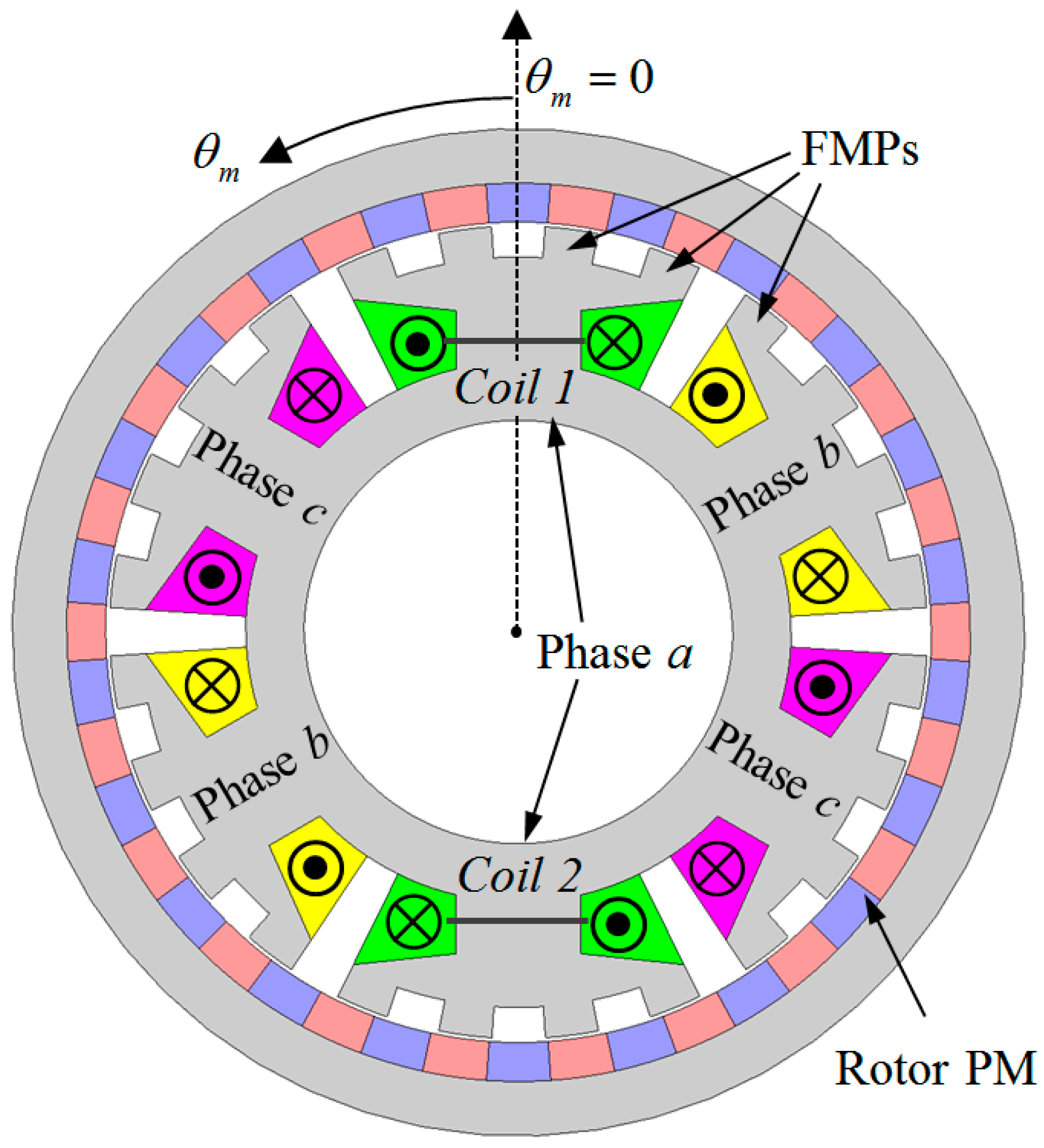
Figure 2 shows a structure of the SPMV machines. The stator has three-phase concentrated windings and each tooth is split into FMPs of the integer number. The MMF distribution created by the three-phase windings can be expressed as [19].
where ps is the number of the winding pole pairs and ωe is the electrical angular speed. In addition, m is the harmonic order of the winding MMF distribution and mps means the spatial harmonic order. The triple harmonics of the winding MMF distribution are cancelled out when the MMF harmonics produced by each phase winding are summed up. Furthermore, the harmonics of orders m = 3i + 1 rotate in the same direction with the fundamental wave of the winding MMF distribution, whereas the harmonics of orders m = 3i − 1 rotate in the opposite direction, where i is an integer. The mechanical angular speed of the mth harmonic can be expressed as:
where, sgn = +1 when m = 3i + 1, whereas sgn = −1 when m = 3i − 1. It is a distinguishing characteristic of the SPMV machine as compared with the magnetic gear of which all the rotor PM MMF harmonics rotate at the same speed and in the same direction.
The air-gap permeance function is determined by the geometry of the FMPs. With assuming that the FMPs are equally spaced and in symmetry with respect to the reference axis of θm as shown in Figure 2, the air-gap permeance function can be expressed as:
where pFMP is the number of the FMPs, j is an integer, and jpFMP is the spatial harmonic order of the air-gap permeance function. When the shapes of the FMPs are designed differently from one another, the air-gap permeance function can include the other spatial orders besides the multiples of pFMP. In this case, j, Pj, and jpFMP in Equation (7) are replaced by k, Pk, and k, respectively, where k is an in integer and describes the spatial harmonic order of the air-gap permeance function.
By multiplying Equations (5) and (7), the radial flux density distribution by the armature windings in the air-gap is given as:
From previous literature, it is well known that the working harmonic of the radial flux density distribution is produced mainly in the 5th term of Equation (8) when m = 1 and j = 1 [15]. Thus, in order to generate the torque by synchronizing with the working harmonic, the number of the rotor pole pairs is determined by:
In addition, the mechanical angular speed of the rotor is given by:
The modulation phenomenon of the magnetic field in the SPMV machine occurs in the same manner with the magnetic gear. However, the angular speed characteristics of the winding MMF harmonics in the SPMV machine are different from that of the rotor PM MMF harmonics in the magnetic gear. The winding MMF harmonics has a helpful effect on the working harmonic by interacting with the specific harmonics of the air-gap permeance function.
When the numbers of the winding pole pairs and the FMPs are 2 and 24, respectively, the number of the rotor pole pairs is 22 by Equation (9). The spatial order and angular speed of the working harmonic becomes 22 and −ωe/22, respectively. Table 2 shows the combinations of the harmonic components that are modulated into the working harmonic. It can be seen that all of the winding MMF harmonics in the SPMV machine can be modulated into the working harmonic unlike the regular PM machines and the magnetic gears. For instance, based on the 4th term of Equation (8), the 4th spatial harmonic of the winding MMF distribution (mps = 4) is changed into the working harmonic by interaction with the 18th spatial harmonic of the air-gap permeance function (k = 18). In general, however, the FMPs are equally spaced and therefore the air-gap permeance function contains only the multiples of 24 harmonics corresponding to the number of the FMPs. This shows that the other harmonics, except for the 2nd and 22th spatial harmonics of the winding MMF distribution, have no influence on the working harmonic generally. Thus, in order to improve the working harmonic and output torque, the shapes of the FMPs should be designed with consideration of the harmonic components of the air-gap permeance function.
3. Design of the Armature Magnetic Field
For this SPMV machine having 6 slots and 24 FMPs, the effects of the winding MMF harmonics on the working harmonic are investigated. Then, the design method for the FMP shape to improve the working harmonic by using the winding MMF harmonics is proposed. The basic dimensions are as follows. The outer diameter of the rotor is 260 mm, the air-gap length is 1 mm, the thickness of the PM is 5 mm, and the core lamination is 24 mm. In addition, the number of the turns per coil is 140. The core materials are 35PN440 and the PMs are NdFeB magnets that have a residual flux density of 1.2 T. In the base model of the SPMV machine, the FMPs are equally spaced, and therefore the angles of each FMP width and the slot open are set as 7.5 degrees. For the basic model, the winding MMF, the air-gap permeance, and the radial flux density in the air-gap of the SPMV machine are calculated by using the analytical and two-dimensional (2-D) FEA methods. To carry out the FEA works, the commercial software, Cedrat FLUX 2-D (Cedrat, Meylan, France) is utilized. In addition, the FMP shapes are designed to improve the working harmonic of the radial flux density by using the winding MMF harmonics.
3.1. Winding MMF Distribution
The winding MMF distribution can be obtained with the following assumptions:
- (1)
- The stator and rotor cores have infinite permeability.
- (2)
- All coils have the same number of turns.
- (3)
- The three-phase currents are symmetric and the sinusoidal waveforms are given by:
where Irms is the root mean square (RMS) value of the input current.
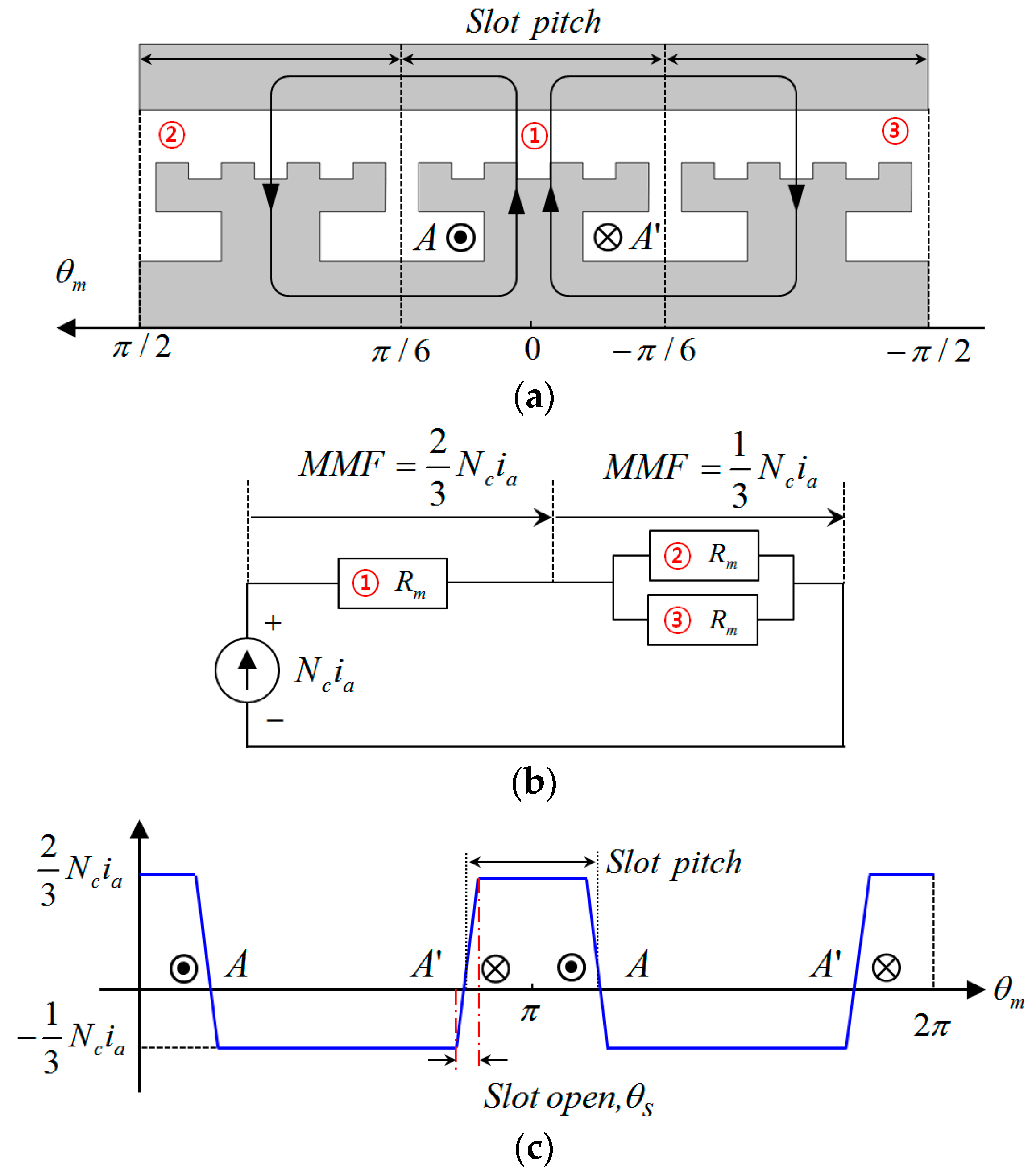
In the SPMV machine having 6 slots, the winding of the phase a includes two coils, and the produced magnetic flux path by each coil of the phase a winding is independent as illustrated in Figure 3a. The magnetic reluctance in the magnetic flux path results from the regions of the air-gap and PMs. Furthermore, the magnetic reluctance per slot pitch, Rm, is identical by assuming that all the teeth have the same shapes. Using Ampere’s law in combination with Gauss’s law, the equivalent magnetic circuit is obtained as shown in Figure 3b. Hence, the amplitude of the produced MMF by the winding of the phase a along the air-gap is expressed as the function including the number of the turns per coil, Nc, and the instantaneous value of the phase a current, ia. When assuming that the values of the MMF are varied linearly in the regions of the slot opening, the MMF distribution by the phase a is as shown in Figure 3c and can be expressed as:
where ps is the number of the winding pole pairs and its value is 2, and θs is the mechanical angle of the slot opening. The MMF distributions by phases b and c can be found in the same manner.
The total MMF distribution is calculated by the sum of the produced MMF by each phase and it is expressed as Equation (5). In addition, the Fourier coefficient for the mth harmonic of the winding MMF distribution in Equation (5) is given by:
3.2. Air-Gap Permeance Function
To investigate the harmonic characteristics of the air-gap permeance function, the FEA method is employed to calculate the magnetic field in the SPMV machine. After the radial flux density distribution by the armature windings in the air-gap is obtained by using the FEA, the air-gap permeance function can be calculated by:
Figure 4a shows the FEA result for the radial flux density distribution by the armature windings in the basic model when the time is zero and the RMS value of the input current is 6 A. Figure 4b shows the winding MMF distribution obtained by using Equations (5) and (14) under the same conditions with the FEA. When the value of the winding MMF is close to zero, the air-gap permeance function has many errors by the division operation of Equation (15). Thus, Section A as shown in Figure 4 is considered to calculate the values of the air-gap permeance function. Since the values of the winding MMF in Section A are constant, the air-gap permeance function in Section A is obtained by Equation (15) without any error, as shown in Figure 4c. In addition, the angle of Section A equals the slot pitch, and therefore the waveform of the air-gap permeance function for Section A is repeated along the circumferential direction.
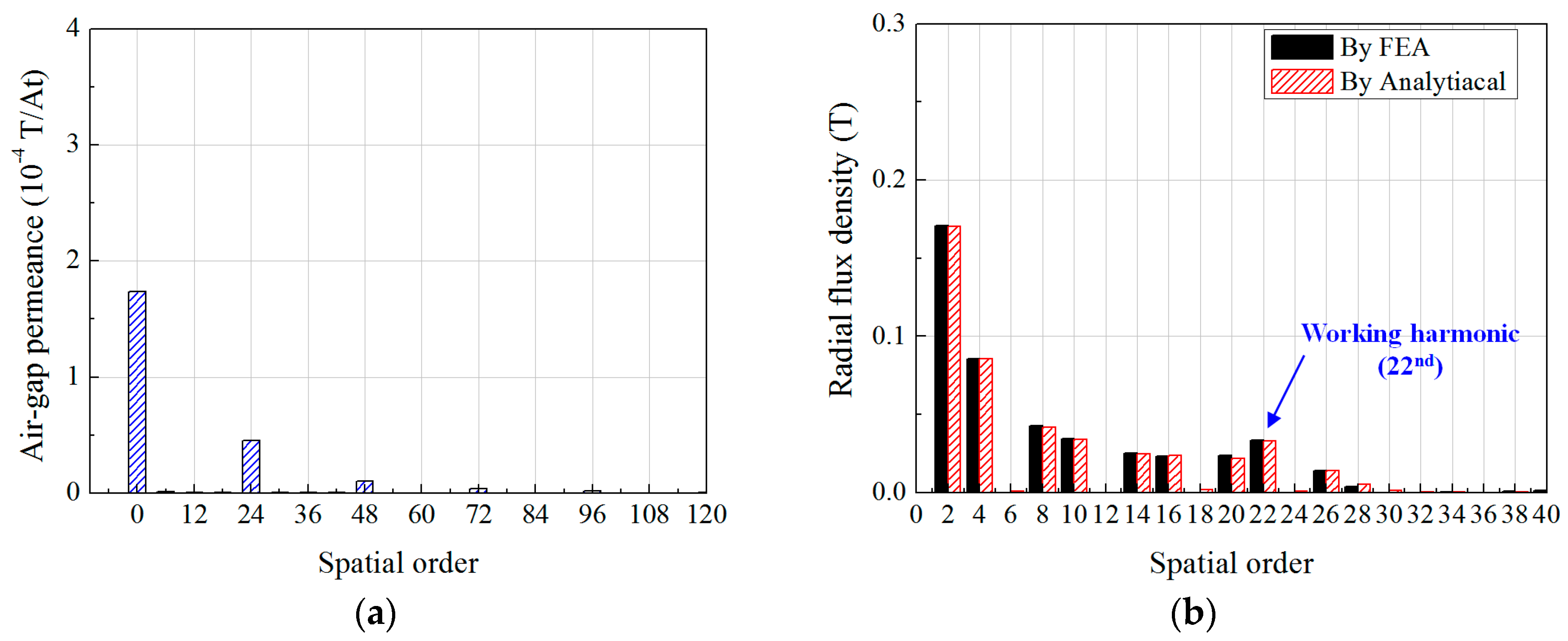
Figure 5a shows the fast Fourier transform (FFT) results for the air-gap permeance function. The air-gap permeance function includes the DC offset value, P0, and the multiples of 24 harmonics. Figure 5b illustrates the FFT results for the radial flux density distribution in the air-gap calculated by the winding MMF distribution and the air-gap permeance function. It shows a good agreement with the FEA results. Thus, the components of the working harmonic can be investigated concretely by the analytical method which is induced by the winding MMF distribution and the air-gap permeance function.
3.3. Effects of The Winding MMF Harmonics
Using the FFT results for the winding MMF distribution and the air-gap permeance function, the Fourier coefficient of the working harmonic is calculated by Equation (8). For the basic model, Table 3 shows the components of the working harmonic that are produced by the spatial harmonics of the winding MMF distribution. In addition, the total amplitude of the working harmonic is compared with the FEA result. It shows a good agreement between both the results. The 2nd and 22nd spatial harmonics of the winding MMF distribution contribute to the amplitude of the working harmonic as 66.7% and 32%, respectively. On the contrary, the other harmonics of the winding MMF distribution have no effects on the working harmonic because the spatial harmonics of the air-gap permeance function, except for the multiples of 24 spatial harmonics, have no amplitudes. In Table 3, the 4th spatial harmonic of the winding MMF distribution has the second highest effect. This indicates that the 4th spatial harmonic has more effects on the working harmonic compared with the other harmonics of the winding MMF distribution. Thus, the 18th spatial harmonic of the air-gap permeance function that can generate the working harmonic by interaction with the 4th spatial harmonic of the winding MMF distribution is considered to design the FMP shapes.
3.4. Design Method for The FMP Shape
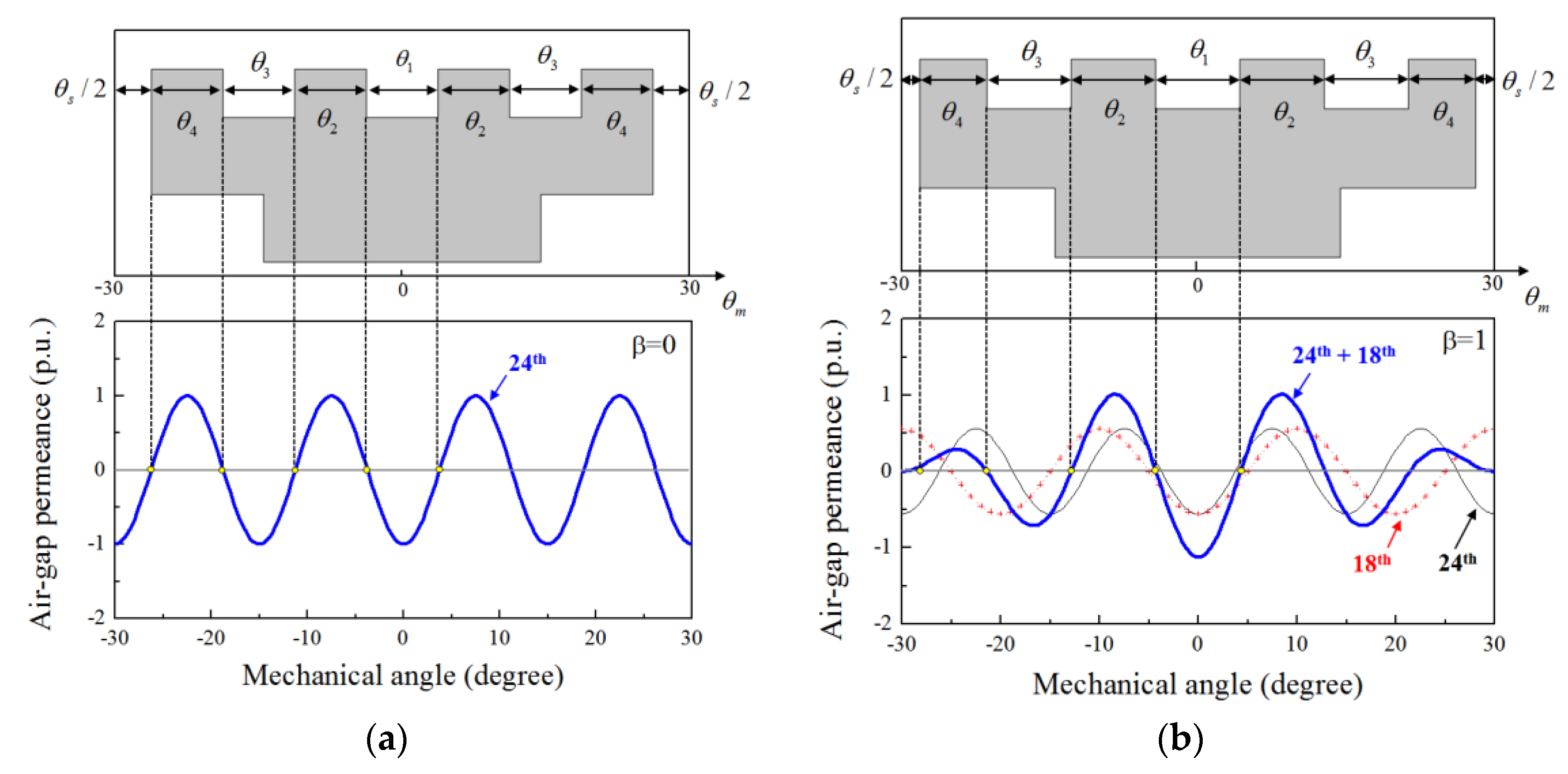
In this section, the method to design the FMP shape by adjusting the harmonic components of the air-gap permeance is presented. To improve the working harmonic by employing the 2nd spatial harmonic of the winding MMF, the 18th spatial harmonic of the air-gap permeance is considered along with the 24th spatial harmonic. In addition, to adjust the amplitude of the 18th spatial harmonic, the design variable, β, is defined as a ratio of the amplitude of the 18th harmonic to that of the 24th harmonic. Figure 6 shows the shapes of the FMPs formed on the tooth that include the 18th spatial harmonic of the air-gap permeance function. The height of the FMPs is fixed as 8 mm and all the teeth have the same shapes of the FMPs. Furthermore, the FMP shapes are in symmetry with respect to the center axis of the tooth. In the basic model, the FMPs are equally spaced and the FMP shapes can be designed by using the waveform of the 24th spatial harmonic. As shown in Figure 6a, the width and location of each FMP are determined by the points in which the amplitude of the 24th spatial harmonic is zero. In the same manner, the shape of the FMPs for including the 18th spatial harmonic of the air-gap permeance can also be designed by using the waveforms of the 18th and 24th spatial harmonics. Based on the FFT results as shown in Table 3, the 18th harmonic of the air-gap permeance should be considered in phase with the 24th harmonic to increase the working harmonic. For example, when β = 1, the shape of the FMPs is obtained as shown in Figure 6b. The waveform of the air-gap permeance consists of the 18th and 24th spatial harmonics having the same amplitude. The width and location of each FMP are determined by the points in which the value of the air-gap permeance is zero. The slot opening is limited to 3.5 degrees for considering the manufacturing condition of the armature windings because the slot opening is diminished accordingly when β is increased. Table 4 shows the dimensions of the design variables for the FMP shape according to β.
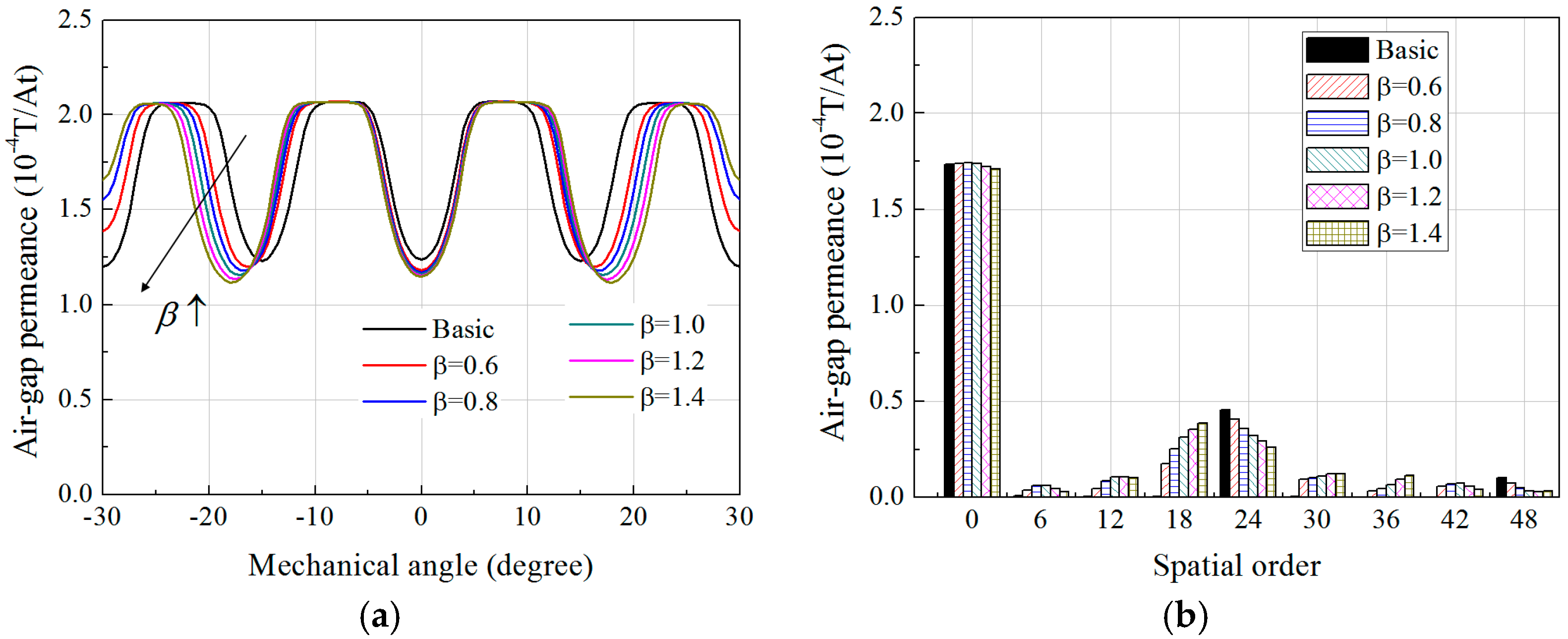
Figure 7 compares the air-gap permeance function obtained by using Equation (15) when the value of β is varied from 0.6 to 1.4. The 18th spatial harmonic of the air-gap permeance function is increased with the rise of β, but the 24th spatial harmonic is decreased. In addition, the FMP shapes that are designed by the values of β additionally contain the multiples of six harmonics, e.g., 6th, 12nd, and 30th spatial harmonics. These spatial harmonics of the air-gap permeance function also have influences on the working harmonic by interaction with the winding MMF harmonics, even though their contribution rates are relatively low.
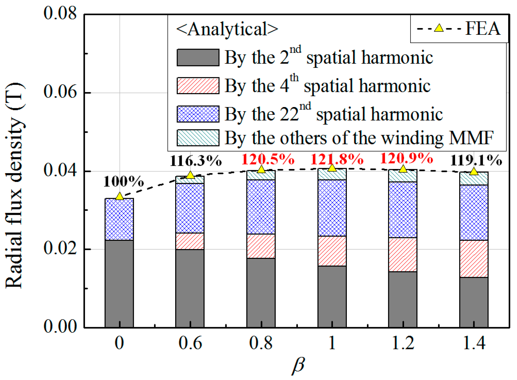
Figure 8 compares the amplitude of the working harmonic obtained by the FEA and analytical methods according to the values of β. It also shows a good agreement between the FEA and analytical methods. When β = 1, the working harmonic is maximized and is improved by 21.8% compared with the basic model in which β = 0. The effects of the 2nd spatial harmonic of the winding MMF distribution on the working harmonic are reduced with the increase of β because the 24th spatial harmonic of the air-gap permeance function is decreased. In contrast, the components of the working harmonic by the other harmonics of the winding MMF are gradually increased with the rise of β. Table 5 shows the components of the working harmonic when β = 1. It can be found that all of the winding MMF harmonics except the 20th spatial harmonic contribute to improving the working harmonic. Since the component of the working harmonic due to the 20th spatial harmonic of the winding MMF has the Fourier coefficient of the different sign from those of the other components of the working harmonic, the 20th spatial harmonic of the winding MMF reduces the amplitude of the whole working harmonic.
4. Performance Analysis
In this section, considering the magnetic field from the rotor PMs, the torque, induced EMF, and efficiency of the SPMV machines are investigated by using the 2-D FEA method. For a fair comparison, all dimensions of the SPMV machine except for the design variables for the FMP shape are applied identically for all analysis models, which are designed by β. In addition, the performance of the SPMV machines with the different shapes of the FMPs are compared under the same analysis conditions, such as the magnetic material, the input current, and the mesh setting. The core materials are 35PN440 and the PMs are NdFeB magnets that have a residual flux density of 1.2 T.
4.1. Torque Characteristics
Figure 9 compares the torque characteristics according to the values of β when the RMS value of the input current, Irms, is equal to 6 A. The average torque tends to vary at a similar percentage with the variations of the working harmonic, as shown in Figure 9b. The average value of the generated torque in the basic model is 47.5 Nm, but the average torque can be improved to 57.7 Nm by applying the FMP shape, in which β = 1. From the analysis results for the average torque, it can be verified that the winding MMF harmonics contribute to improving the torque characteristics of the SPMV machine by applying the design method for the FMP shapes which is proposed in this paper. Figure 9c shows the variations of the torque ripple and cogging torque according to the values of β. The characteristics of the torque ripple depend on the cogging torque. When β = 0.8, the cogging torque is maximum and the torque ripple is increased up to 14% by the cogging torque. On the contrary, when β = 1.2, the torque ripple can be minimized as 1.3% and the average torque is 57.2 Nm. It is shown that the torque ripple and cogging torque can be reduced by adjusting the value of β while increasing the average torque.
4.2. Induced EMF Characteristics under the No-Load Condition
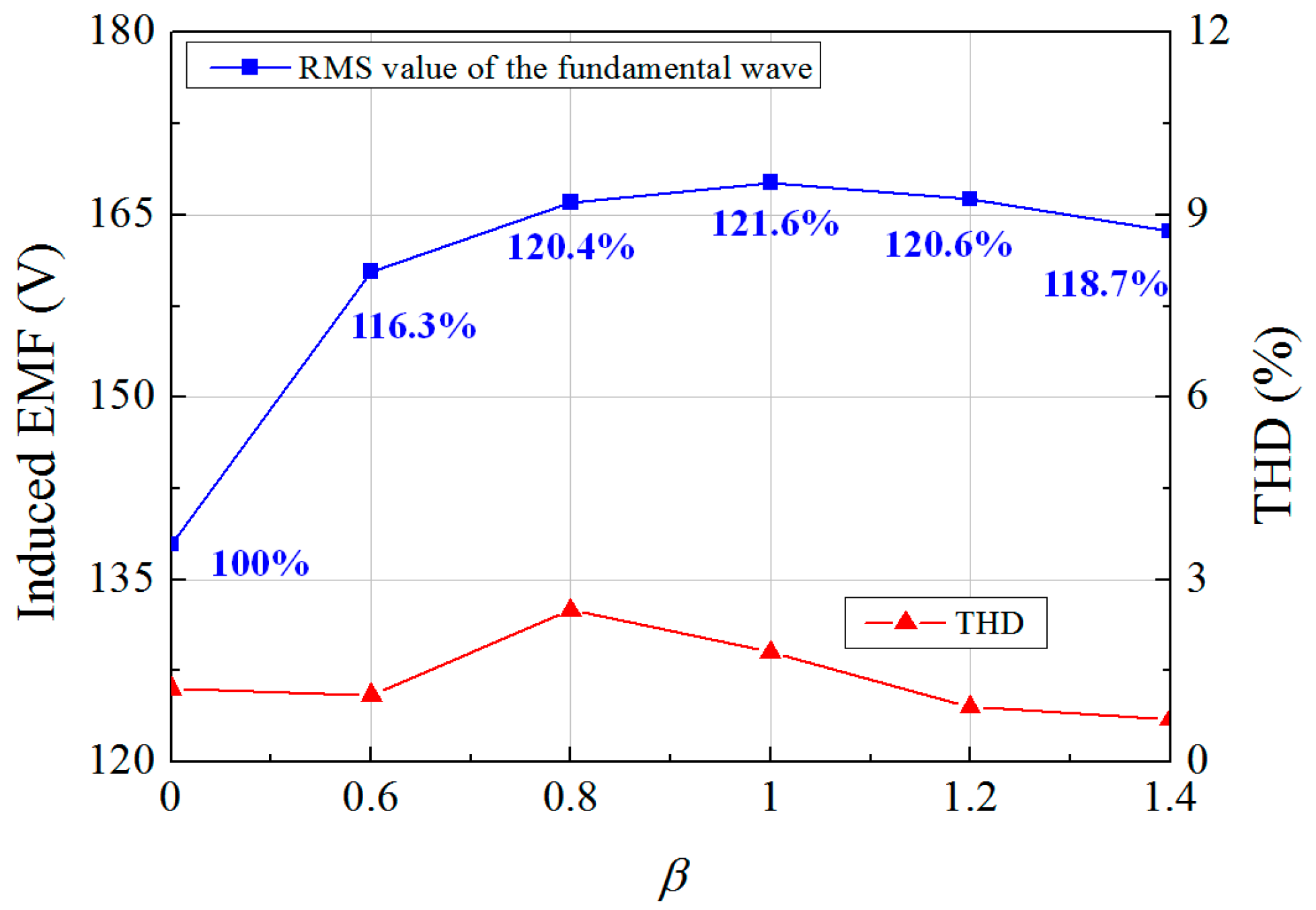
Figure 10 shows the variations of the induced EMF characteristics under the no-load condition according to the values of β when the rotating speed of the rotor is 500 rpm. The total harmonic distortion (THD) of the induced EMF has a value lower than 2.5% for all SPMV machines which have different shapes of the FMPs. However, the RMS values of the fundamental wave of the induced EMF waveform tend to vary similarly with the changes of the working harmonic. It is due to the magnetic field modulation of the rotor PM MMF by the FMPs. It was described previously that the winding MMF distribution is changed by the FMPs into the magnetic field corresponding to the rotor PM MMF distribution. In the same manner, the distribution of the rotor PM MMF is also modulated and then the resulting magnetic field generates the induced EMF waveform with the rotation of the rotor PM under the no-load condition. Thus, the designed shapes of the FMPs to increase the working harmonic can improve the average torque and induced EMF at the same rate.
4.3. Efficiency
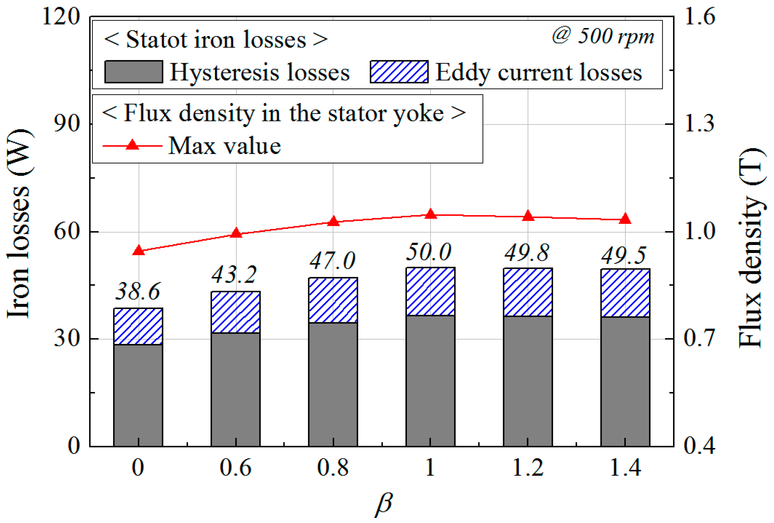
Based on the iron loss model proposed by Bertotti, the hysteresis and eddy current losses in the stator core are calculated by employing Cedrat FLUX 2-D (Cedrat, Meylan, France) [20]. The coefficient of the hysteresis loss is found by using the experimental values of the iron losses for the magnetic flux density and frequency, which are provided by the manufacturer of 35PN440. In the case of the eddy current losses, the volume density of the instantaneous loss is calculated in each element of the FEA model, and then the average loss, which is dissipated in a volume region over a period, is obtained. Thus, the harmonic components of the flux density waveform with time in the regions of the stator core are considered in the eddy current loss. Figure 11 compares the iron losses in the stator cores having different shapes of the FMPs. The rotating speed of the rotor is 500 rpm and the fundamental frequency is 183.3 Hz. In the SPMV machines, under the load condition, the amount of the magnetic flux through the stator core is increased with the rise of the average torque. Since the eddy current losses are relatively small and the hysteresis losses are dominant as shown in Figure 11, the iron losses in the stator core tend to be proportional to the max value of the flux density in the stator yoke.
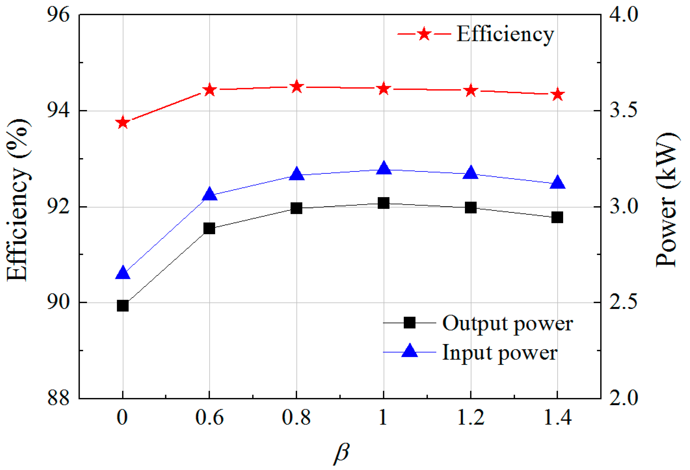
Figure 12 shows the efficiency according to the values of β. The efficiency is a ratio of the mechanical output power to the input power and the input power is calculated by the sum of the output power, stator iron losses, and copper losses. Since the copper loss of the armature windings is identical to 126.9 W, the efficiency of the SPMV machine depends on the average torque and the iron losses in the stator core. It can be seen that the efficiency of the SPMV machines having the designed FMP shapes is also improved with the increase of the average torque.
5. Conclusions
This paper presents the influences of the winding MMF harmonics on the output torque in the SPMV machine. The operating principle of the SPMV machine is elaborated by using the analytical equation which is derived from the winding MMF distribution and the air-gap permeance function. Consequently, it can be found that the winding MMF harmonics affect the working harmonic of the air-gap flux density by interacting with the specific harmonics of the air-gap permeance. For the SPMV machine having 6 slots and 24 FMPs, the winding MMF, the permeance, and the flux density in the air-gap are calculated by using the analytical and FEA methods. The analysis results show that the winding MMF harmonics have no influences on the working harmonic of the flux density in the air-gap when the FMPs are equally spaced. Hence, to improve the working harmonic by employing the winding MMF harmonics, the FMP shapes are designed by adjusting the harmonic characteristics of the air-gap permeance. As a result, the working harmonic and output torque of the SPMV machine are increased by 21.6% compared with the basic model. Furthermore, the proposed design method for the FMP shape also improves the induced EMF under the no-load condition and the efficiency. It can be concluded that the output torque of the SPMV machine can be improved by considering the design of the harmonic characteristics of the winding MMF distribution and the air-gap permeance. In addition, the geometry of the FMPs should be designed considering the resulting harmonics of the air-gap permeance. In future research, the winding configurations that determine the harmonic characteristics of the winding MMF will be analyzed and developed for the high torque density of the SPMV machine. Then, the effects of the winding MMF harmonic on the torque in the other topologies of the PMV machines will be investigated.
Acknowledgments
This research was supported by Basic Science Research Program through the National Research Foundation of Korea (NRF) funded by the Ministry of Education (NRF-2015R1D1A1A01059637).
Author Contributions
All authors have contributed to this work. Daekyu Jang was the main author of this manuscript and contributed to the theoretical analysis, modeling, simulation, and manuscript preparation. Junghwan Chang provided technical guidance for research work and supervised the whole project.
Conflicts of Interest
The authors declare no conflict of interest.
References
- Li, J.; Chau, K.T.; Jiang, J.Z.; Liu, C.; Li, W. A new efficient permanent-magnet vernier machine for wind power generation. IEEE Trans. Magn. 2010, 46, 1475–1478. [Google Scholar] [CrossRef]
- Yang, H.; Lin, H.; Zhu, Z.-Q.; Fang, S.; Huang, Y. Dual-consequent-pole vernier memory machine. Energies 2016, 9, 134. [Google Scholar] [CrossRef]
- Liu, G.; Yang, J.; Zhao, W.; Ji, J.; Chen, Q.; Gong, W. Design and analysis of a new fault-tolerant permanent-magnet vernier machine for electric vehicles. IEEE Trans. Magn. 2012, 48, 4176–4179. [Google Scholar] [CrossRef]
- Zhao, F.; Kim, M.S.; Kwon, B.I.; Baek, J.H. A small axial-flux vernier machine with ring-type magnets for the auto-focusing lens drive system. IEEE Trans. Magn. 2016, 52, 1–4. [Google Scholar] [CrossRef]
- Du, Y.; Cheng, M.; Chau, K.T.; Liu, X.; Xiao, F.; Zhao, W. Linear primary permanent magnet vernier machine for wave energy conversion. IET Electr. Power Appl. 2015, 9, 203–212. [Google Scholar] [CrossRef]
- Ho, S.L.; Niu, S.; Fu, W.N. Design and comparison of vernier permanent magnet machines. IEEE Trans. Magn. 2011, 47, 3280–3283. [Google Scholar] [CrossRef]
- Wu, L.; Qu, R.; Li, D.; Gao, Y. Influence of pole ratio and winding pole numbers on performance and optimal design parameters of surface permanent-magnet vernier machines. IEEE Trans. Ind. Appl. 2015, 51, 3707–3715. [Google Scholar] [CrossRef]
- Li, D.; Qu, R.; Xu, W.; Li, J.; Lipo, T.A. Design procedure of dual-stator spoke-array vernier permanent-magnet machines. IEEE Tran. Ind. Appl. 2015, 51, 2972–2983. [Google Scholar] [CrossRef]
- Jang, D.K.; Chang, J.H. Design of a vernier machine with pm on both sides of rotor and stator. IEEE Trans. Magn. 2014, 50, 877–880. [Google Scholar] [CrossRef]
- Li, X.; Chau, K.T.; Cheng, M. Analysis, design and experimental verification of a field-modulated permanent-magnet machine for direct-drive wind turbines. IET Electr. Power Appl. 2015, 9, 150–159. [Google Scholar] [CrossRef]
- Vukotić, M.; Miljavec, D. Design of a permanent-magnet flux-modulated machine with a high torque density and high power factor. IET Electr. Power Appl. 2016, 10, 36–44. [Google Scholar] [CrossRef]
- Zhu, Z.Q.; Howe, D. Instantaneous magnetic field distribution in brushless permanent magnet DC motors. Iii. Effect of stator slotting. IEEE Trans. Magn. 1993, 29, 143–151. [Google Scholar] [CrossRef]
- Zhu, Z.Q.; Howe, D. Influence of design parameters on cogging torque in permanent magnet machines. IEEE Trans. Energy Convers. 2000, 15, 407–412. [Google Scholar] [CrossRef]
- Fornasiero, E.; Bianchi, N.; Bolognani, S. Slot harmonic impact on rotor losses in fractional-slot permanent-magnet machines. IEEE Trans. Ind. Electron. 2012, 59, 2557–2564. [Google Scholar] [CrossRef]
- Toba, A.; Lipo, T.A. Generic torque-maximizing design methodology of surface permanent-magnet vernier machine. IEEE Trans. Ind. Appl. 2000, 36, 1539–1546. [Google Scholar]
- Kim, B.; Lipo, T.A. Operation and design principles of a PM vernier motor. IEEE Trans. Ind. Appl. 2014, 50, 3656–3663. [Google Scholar] [CrossRef]
- Yang, J.; Liu, G.; Zhao, W.; Chen, Q.; Jiang, Y.; Sun, L.; Zhu, X. Quantitative comparison for fractional-slot concentrated-winding configurations of permanent-magnet vernier machines. IEEE Trans. Magn. 2013, 49, 3826–3829. [Google Scholar] [CrossRef]
- Atallah, K.; Calvwelwy, S.D.; Howe, D. Design, analysis and realization of a high-performance mangetic gear. IET Electr. Power Appl. 2004, 151, 135–143. [Google Scholar] [CrossRef]
- Clayton, A.E. A mathematical development of the theory of the magnetomotive force of windings. J. Inst. Electr. Eng. 1923, 61, 749–787. [Google Scholar] [CrossRef]
- Bertotti, G. General properties of power losses in soft ferromagnetic materials. IEEE Trans. Magn. 1988, 24, 621–630. [Google Scholar] [CrossRef]
Figure 1.
A structure of the magnetic gear.

Figure 2.
A structure of the SPMV machines with concentrated windings.

Figure 3.
Winding MMF produced by the winding of the phase a. (a) Magnetic flux path; (b) Equivalent magnetic circuit; (c) Winding MMF distribution.
Figure 3.
Winding MMF produced by the winding of the phase a. (a) Magnetic flux path; (b) Equivalent magnetic circuit; (c) Winding MMF distribution.

Figure 4.
Distributions of (a) the radial components of the air-gap flux density by the armature windings; (b) the winding MMF; and (c) the air-gap permeance.
Figure 4.
Distributions of (a) the radial components of the air-gap flux density by the armature windings; (b) the winding MMF; and (c) the air-gap permeance.
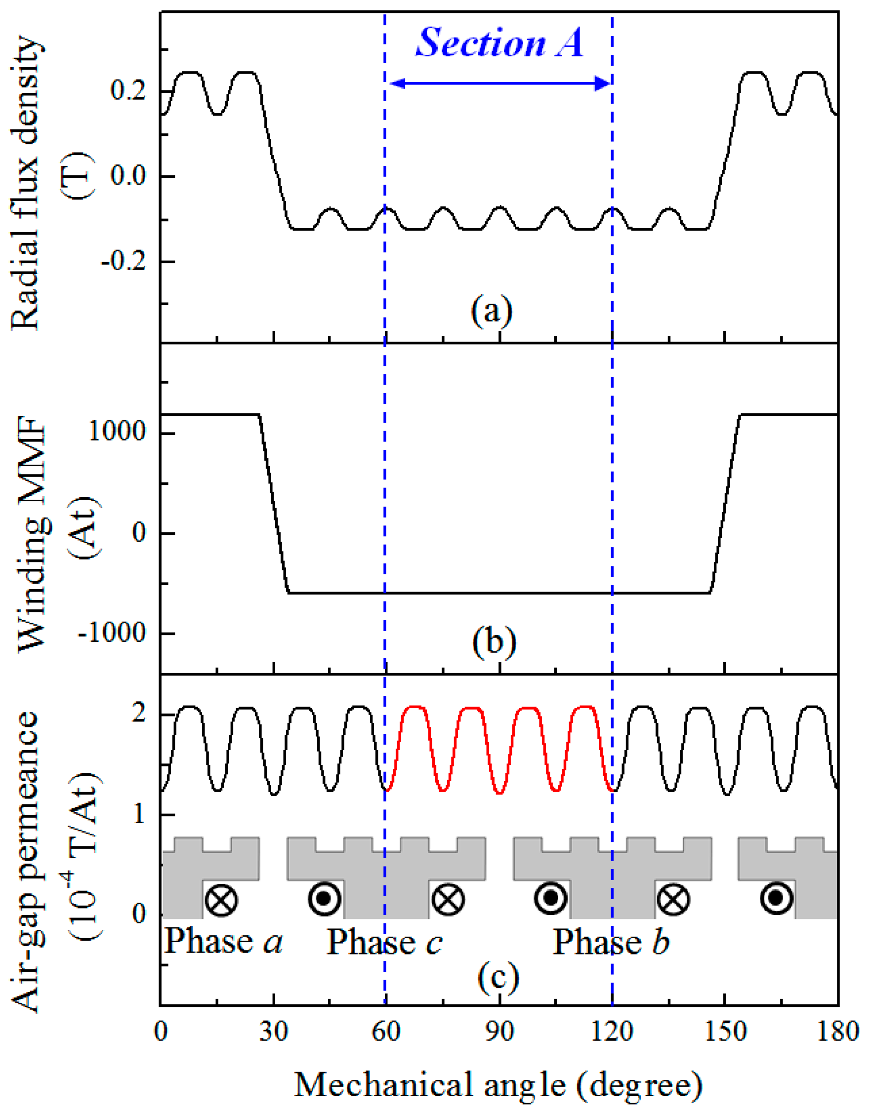
Figure 5.
FFT results for (a) the air-gap permeance function; and (b) the radial flux density distribution calculated by the winding MMF distribution and the air-gap permeance function.
Figure 5.
FFT results for (a) the air-gap permeance function; and (b) the radial flux density distribution calculated by the winding MMF distribution and the air-gap permeance function.

Figure 6.
Basic and designed shapes of the FMPs. (a) Basic shape; (b) Designed shape including the 18th harmonic of the air-gap permeance function (β = 1).
Figure 6.
Basic and designed shapes of the FMPs. (a) Basic shape; (b) Designed shape including the 18th harmonic of the air-gap permeance function (β = 1).

Figure 7.
Air-gap permeance functions according to the values of β. (a) Waveforms; (b) Spatial harmonic components.
Figure 7.
Air-gap permeance functions according to the values of β. (a) Waveforms; (b) Spatial harmonic components.

Figure 8.
Working harmonics obtained by the FEA and analytical methods according to the values of β.
Figure 8.
Working harmonics obtained by the FEA and analytical methods according to the values of β.

Figure 9.
Torque characteristics according to the values of β. (a) Waveforms; (b) Average torque and working harmonic and (c) Torque ripple and cogging torque.
Figure 9.
Torque characteristics according to the values of β. (a) Waveforms; (b) Average torque and working harmonic and (c) Torque ripple and cogging torque.
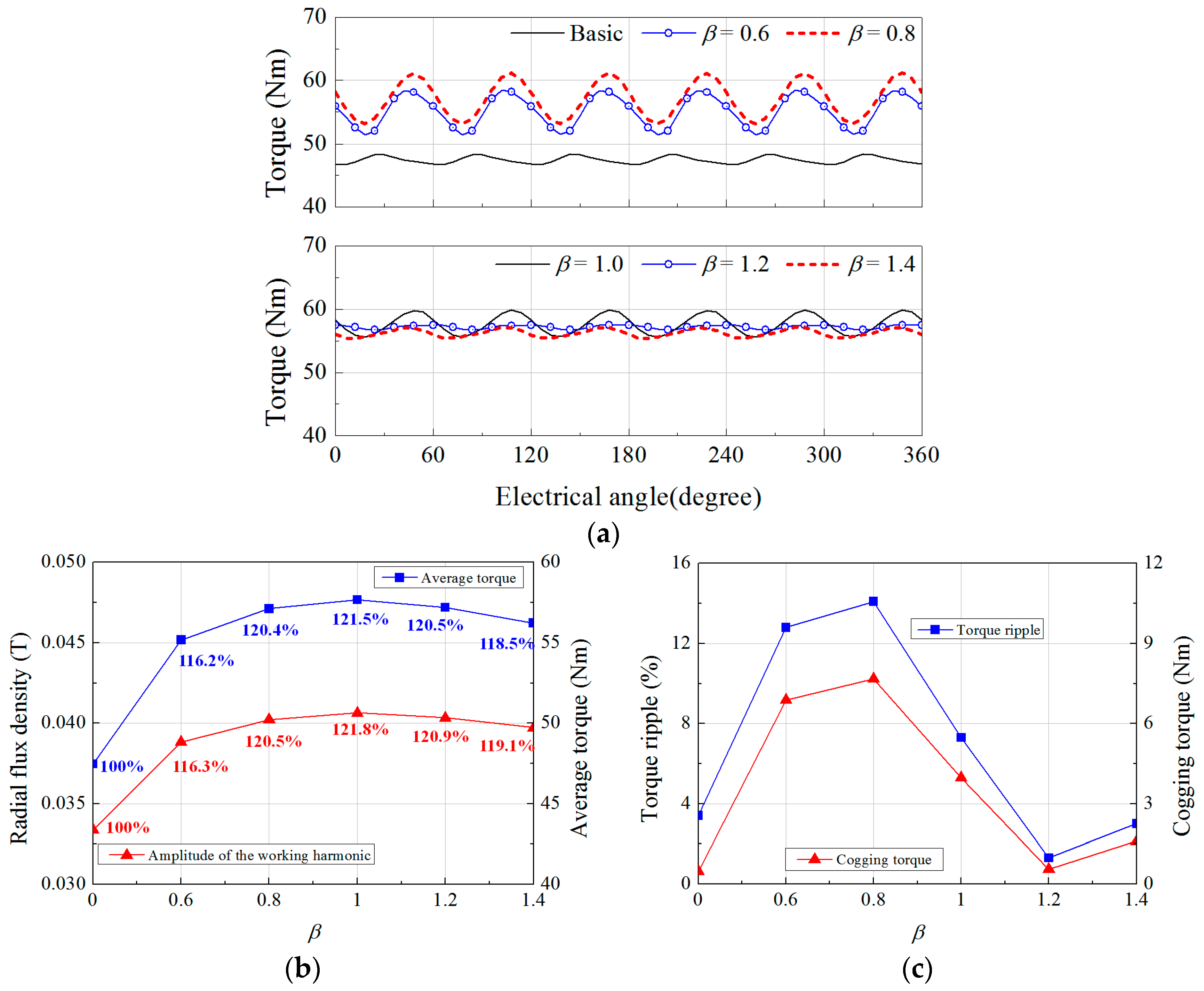
Figure 10.
Induced EMF characteristics under the no-load condition according to the values of β.

Figure 11.
Stator iron losses and the flux density in the stator yoke according to the values of β.

Figure 12.
Efficiency and power according to the values of β.


Table 1.
Combinations of the harmonics that are modulated into the 22nd spatial harmonic of the radial flux density in the outer air-gap.
Table 1.
Combinations of the harmonics that are modulated into the 22nd spatial harmonic of the radial flux density in the outer air-gap.
| Spatial Harmonic Order of the Winding MMF, mpir | Spatial Harmonic Order of the Permeance, v | By Term of Equation (2) | The Modulated Harmonic | |
|---|---|---|---|---|
| Spatial Order | Speed | |||
| 4 | 26 | 3rd | 22 | −4/22 × ωir |
| 12 | 10 | 2nd | +12/22 × ωir | |
| 20 | 2 | 2nd | +20/22 × ωir | |
| 28 | 6 | 3rd | −28/22 × ωir | |
Table 2.
Combinations of the harmonics that are modulated into the working harmonic.
| Spatial Harmonic Order of the Winding MMF, mps | Spatial Harmonic Order of the Permeance, k | By Term of Equation (8) | The Modulated Harmonic | |
|---|---|---|---|---|
| Spatial Order | Speed | |||
| 2 | 24 | 5th | 22nd | −ωe/22 |
| 4 | 18 | 4th | ||
| 8 | 30 | 5th | ||
| 10 | 12 | 4th | ||
| 14 | 36 | 5th | ||
| 16 | 6 | 4th | ||
| 20 | 42 | 5th | ||
| 22 | 0 | 2nd | ||
Table 3.
Components of the working harmonic in the basic model.
| Winding MMF Harmonics | Air-Gap Permeance Harmonics | Working Harmonic (22nd ) | |||
|---|---|---|---|---|---|
| Spatial Order | Fourier Coefficient (At) | Spatial Order | Fourier Coefficient (T/At) | Fourier Coefficient (T) | Percent (%) |
| 2 | 979.61 | 24 | −4.5 × 10⁻⁵ | −0.02225 | 66.7 |
| 4 | 485.62 | 18 | 0 | 0 | 0 |
| 8 | −234.54 | 30 | 0 | 0 | 0 |
| 10 | −182.75 | 12 | 0 | 0 | 0 |
| 14 | 121.51 | 36 | 0 | 0 | 0 |
| 16 | 101.56 | 6 | 0 | 0 | 0 |
| 20 | −72.49 | 42 | 0 | 0 | 0 |
| 22 | −61.50 | 0 | 1.7 × 10⁻⁴ | −0.01067 | 32.0 |
| Sum | −0.03280 | 98.7 | |||
| The FEA result | −0.03336 | 100 | |||
Table 4.
Dimensions of the design variables according to β.
| β | Design Variables (Degree) | ||||
|---|---|---|---|---|---|
| θ1 | θ2 | θ3 | θ4 | θs | |
| 0 (Basic model) | 7.5 | 7.5 | 7.5 | 7.5 | 7.5 |
| 0.6 | 8.27 | 8.21 | 7.93 | 6.9 | 5.64 |
| 0.8 | 8.44 | 8.4 | 8.23 | 7.02 | 4.26 |
| 1.0 | 8.57 | 8.57 | 8.57 | 6.82 | 3.5 |
| 1.2 | 8.69 | 8.72 | 8.92 | 6.27 | 3.5 |
| 1.4 | 8.78 | 8.84 | 9.24 | 5.78 | 3.5 |
Table 5.
Components of the working harmonic when β = 1.
| Winding MMF Harmonics | Air-Gap Permeance Harmonics | Working Harmonic (22nd ) | |||
|---|---|---|---|---|---|
| Spatial Order | Fourier Coefficient (At) | Spatial Order | Fourier Coefficient (T/At) | Fourier Coefficient (T) | Percent (%) |
| 2 | 981.81 | 24 | −3.2 × 10⁻⁵ | −0.01570 | 38.6 |
| 4 | 489.99 | 18 | −3.1 × 10⁻⁵ | −0.00768 | 18.9 |
| 8 | −243.17 | 30 | 1.1 × 10⁻⁵ | −0.00132 | 3.3 |
| 10 | −193.44 | 12 | 1.1 × 10⁻⁵ | −0.00101 | 2.5 |
| 14 | 136.11 | 36 | −6.5 × 10⁻⁶ | −0.00044 | 1.1 |
| 16 | 117.97 | 6 | −6.4 × 10⁻⁶ | −0.00038 | 0.9 |
| 20 | −92.24 | 42 | −7.1 × 10⁻⁶ | 0.00033 | −0.8 |
| 22 | −82.74 | 0 | 1.7 × 10⁻⁴ | −0.01437 | 35.4 |
| Sum | −0.04057 | 99.9 | |||
| The FEA result | −0.04063 | 100 | |||
© 2017 by the authors. Licensee MDPI, Basel, Switzerland. This article is an open access article distributed under the terms and conditions of the Creative Commons Attribution (CC BY) license (http://creativecommons.org/licenses/by/4.0/).
Share and Cite
MDPI and ACS Style
Jang, D.; Chang, J. Influences of Winding MMF Harmonics on Torque Characteristics in Surface-Mounted Permanent Magnet Vernier Machines. Energies 2017, 10, 580. https://doi.org/10.3390/en10040580
AMA Style
Jang D, Chang J. Influences of Winding MMF Harmonics on Torque Characteristics in Surface-Mounted Permanent Magnet Vernier Machines. Energies. 2017; 10(4):580. https://doi.org/10.3390/en10040580
Chicago/Turabian StyleJang, Daekyu, and Junghwan Chang. 2017. "Influences of Winding MMF Harmonics on Torque Characteristics in Surface-Mounted Permanent Magnet Vernier Machines" Energies 10, no. 4: 580. https://doi.org/10.3390/en10040580
Note that from the first issue of 2016, this journal uses article numbers instead of page numbers. See further details here.