
Optimal Control Based on Maximum Power Point Tracking (MPPT) of an Autonomous Hybrid Photovoltaic/Storage System in Micro Grid Applications

1
Electrical Engineering Department, Faculty of Engineering, University of Tabuk, Tabuk 71491, Saudi Arabia
2
Electrical Engineering Department, Faculty of Engineering, Sohag University, Sohag 82524, Egypt
*
Author to whom correspondence should be addressed.
Energies 2017, 10(5), 643; https://doi.org/10.3390/en10050643
Submission received: 3 March 2017
/
Revised: 7 April 2017
/
Accepted: 16 April 2017
/
Published: 7 May 2017
(This article belongs to the Special Issue Advanced Operation and Control of Smart Microgrids)
Abstract
:This paper investigates how to increase the efficiency of a photovoltaic/energy storage generation unit supplying dynamic loads by regulating and managing both the photovoltaic generator and the storage battery charge-discharge modes. The proposed photovoltaic/energy storage unit is proposed to supply an induction motor driven industrial pump with controlled speed and/or a DC motor driven water pump. An optimal proportional-integral-derivative control based on an Artificial Bee Colony Optimization algorithm is used to regulate the photovoltaic generator in case of normal operation or in case of maximum power point tracking (MPPT) and to also control the battery storage charge discharge modes. A vector control based on the proposed optimal control is used to regulate the induction motor rotor speed at its low reference values needed by the industrial pump. First, a total model of the entire system is obtained. The controller performance with the proposed system is studied with both a DC motor and/or induction motor loads. Simulation results show that the proposed photovoltaic/storage generator is able to supply the suggested dynamic loads under different conditions and with good performance. Also, it is noticed that operating the photovoltaic base on maximum power point tracking condition will give about 43% extra generation power than the normal operation case.
1. Introduction
Photovoltaic (PV)/storage energy systems have increased interest in electrical power applications [1]. However, the design and operation of such systems are challenging due to the absence of the main grid supply [2,3]. Also due to the fact PV cannot operate during the night, the use of an energy storage device such as a battery can significantly improve the reliability of small autonomous PV systems [4,5].
It is important to operate the photovoltaic power generation unit near the maximum power point to increase the efficiency of the system [6,7]. The current and power of a PV array depend mainly on the array terminal operating voltage. In addition, the maximum power operating point varies with the insolation level and temperature. Therefore, the tracking control of the maximum power point is a complicated problem. To overcome these problems, many tracking control strategies have been proposed such as reactive power control [8], fuzzy logic controller (FLC) [9], neural network [10], and incremental conductance [11].
The general requirements for maximum power point tracking (MPPT) are simplicity and low cost, quick tracking under changing conditions, and small output power fluctuation [12]. More efficient methods to solve this problem are crucially important. In a PV pumping system, maximum power transfer is expected between the PV solar panel and the pump motor over a wide insolation interval [13]. If not, the performance may drop to low values. If the load voltage or current is controlled to be constant, this will lead to maximum power decrease [14].
Recently, the Artificial Bee Colony Optimization (ABCO) approach was introduced and successfully used to solve different optimization problems such as distributed optimization and control [15], optimization design of power system stabilizers [16], renewable power generations and control [17]. However, the artificial bee colony approach has important advantages as it can be applied efficiently to solve multimodal engineering problems with high dimensionality and requires less control parameter to be tuned [18].
This paper presents a method to extract the maximum power from a PV/storage generation unit which drives a dynamic load at the available high efficiency by tracking the maximum power available by the PV/energy storage unit based on optimal control. The proposed dynamic load includes both an IM-industrial pump and a DC motor-water pump system which can be used in industrial and irrigation applications. The effectiveness of the PV generator, energy storage unit, water pumping system and induction motor (IM)-industrial pump system together with the proposed optimized proportional-integral-derivative (PID) controllers has been demonstrated through computer simulations. Moreover, the proposed controller with the applied MPPT method is compared with the case where MPPT is not applied. Simulation results also show the ability of the proposed PV/storage generator unit to supply the suggested dynamic loads at different conditions with good performance and give about 43% extra power in the case the PV/storage unit is operating under MPPT conditions.
2. System Configuration
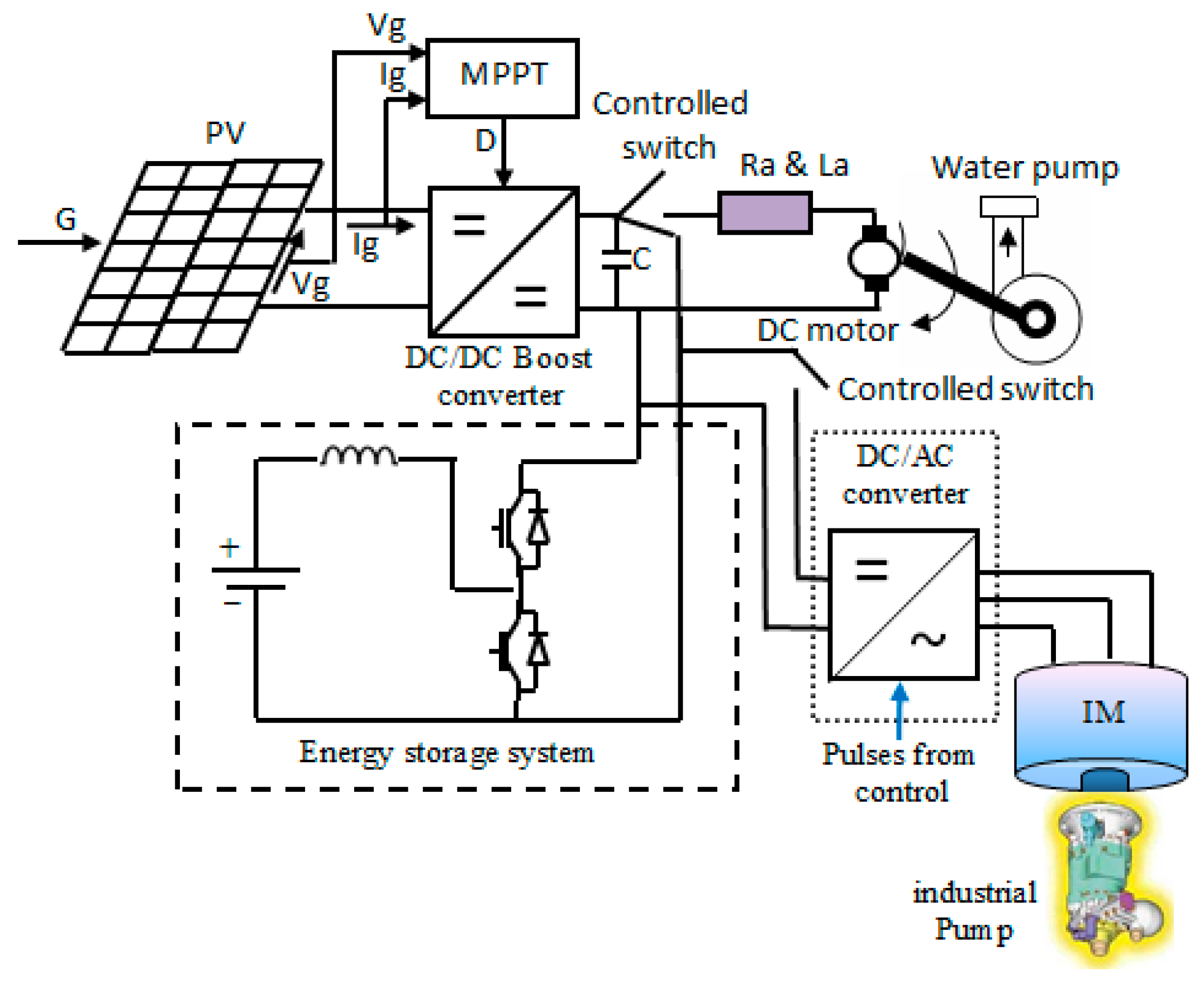
Figure 1 shows a photovoltaic energy system connected to an isolated load using a controlled DC/DC converter. It consists of a PV unit, which supplies a DC motor and IM-drives a variable-displacement pressure compensated (VDPC) industrial pump as an isolated load. A lead acid battery (LAB) is connected to the DC-side of the DC-link. The DC/DC converter is a boost converter controlled based on a MPPT technique using an optimized PID controller via an ABCO approach.
Generally, the PV output voltage which supplies an isolated load depends mainly on the isolation level and the load. Therefore, if the load changes, or/and, if the isolation changes, there is a possibility that the load voltage will change. This is objectionable for sensitive loads. In this study, an optimized PID controller based on an ABCO algorithm and the MPPT technique are used to control the DC output voltage of the boost converter and use of a storage system with a suitable controller have been proposed to overcome this problem. A vector control based on the proposed optimal control is applied to control the IM rotor speed.
3. System Mathematical Modeling
The model of the entire solar energy system can be divided into several interconnected subsystem models as shown in Figure 1. These subsystems are the PV, the boost converter, the storage system, the DC motor and the IM-industrial pump system.
3.1. PV Generator Model
The PV generator consists of solar cells composed of series and parallel units to supply the desired voltage and current needed by the load, which can give about 1700 W in normal operation and about 2200 W in MPPT condition. The PV parameters values are shown in Table 1. The photovoltaic generator units represented by a nonlinear voltage-current which characteristics mainly depend on the insolation and the temperature, as shown in Equation (1) [19]:
where:
where Vg is the output voltage of the PV generator; Ig is the output current of the PV generator; Ag is the PV generator constant; q is the charge of the electron; Z is the Boltzmann constant; U is the absolute temperature; ε is the completion factor; Ns is the number of series-connected solar cells; Np is the parallel paths of PV modules; Rsg is the series resistance of the PV generator; Rs is the series resistance per cell; Iphg = Iph × Np is the photo current of the PV generator insolation-dependent; Iph is the photo current per cell; Iog = Io × Np is the reverse saturation current of the PV generator; Io is the reverse saturation current per cell; G is the solar irradiance in per unit, and 1.0 per unit of G = 1000 W/m2.
Ag = (q/(ε × Z × U))/Ns, Io × Np, Rsg = Rs × (Ns/Np) and Iphg = Io × Np × Np
3.2. DC-DC Converter
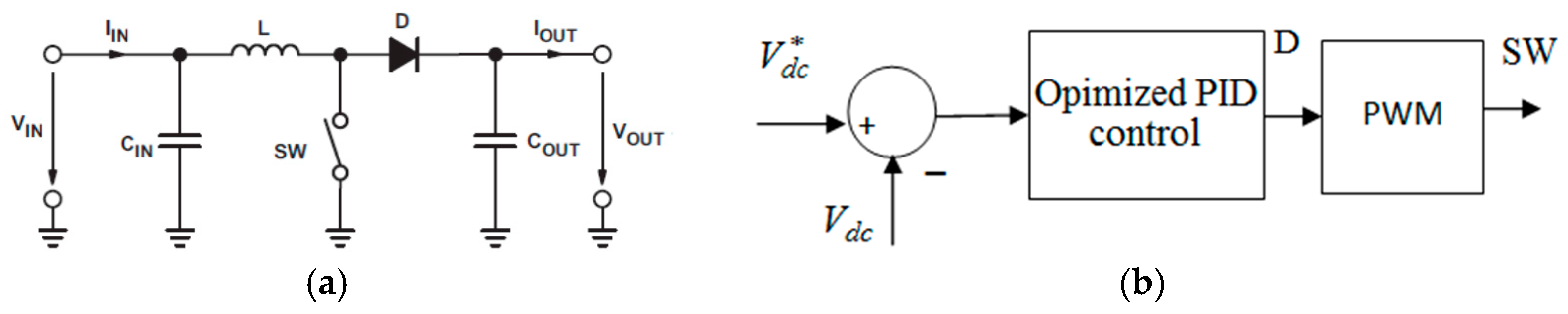
In this paper, the DC/DC converter is implemented using a unidirectional boost converter to interface the PV generator to the DC motor and the battery. Its function is to regulate the transfer of power. The circuit diagram of the simple boost converter and its proposed controller are shown in Figure 2a,b, respectively.
The voltage and current relationships for the primary and secondary sides are given by [20]:
where D is the duty cycle ratio of the DC/DC converter, Vdct is the DC/DC converter terminal output voltage and Idc is the DC/DC converter output current.
3.3. Energy Storage System
In this study, it is proposed that the energy storage unit is composed of a bank of LABs, a single-phase, bidirectional DC/DC converter as shown in Figure 1. The batteries are able to supply the power provided to the load by the PV generation system, when the insolation level is too low. The LAB equivalent model contains the LAB voltage (Vbat) and the internal resistance connected in series with the controlled voltage source (Eb). It is known that the Eb voltage depends on the charging state and the battery type [20,21].
3.4. DC Motor/Water Pump Model
The permanent magnet DC motor dynamics and its load can be represented by the following set of equations with constant coefficients [19]:
The pump load torque can be represented as follows [19]:
3.5. Induction Motor and VDPC Pump
In this paper, a general industrial VDPC pump driven by a controlled induction motor is proposed. Details about the industrial VDPC pump model are shown in [13]. An induction motor mathematical model is obtained based on rotor and stator voltage equations in a synchronous frame as shown below [13]:
where is the electromagnetic torque developed by the motor:
4. The MPPT Technique
In this paper, tracking the maximum available power from the PV generation unit based on the incremental conductance approach is presented. This approach has the advantage that it can determine when the maximum power point tracker has reached the maximum power point, whereas some of other available algorithms oscillate around the maximum power point. Also, this MPPT algorithm can track rapidly increasing and decreasing insolation conditions with higher accuracy. In this MPPT method, the slope of the power over voltage is set to be zero at maximum power condition. Hence, the output voltage of the photovoltaic generation unit is changed until the ratio dP/dV reaches zero, which means that the PV generator is working at MPPT condition. Equation (14) shows the principles of the proposed method, however the ratio dP/dV can follow one of the following cases [22]:
The MPPT approach based on the incremental conductance algorithm and the ABCO technique are applied to optimize the PID controllers. However, the ABCO algorithm is applied to obtain the optimal values of the PID regulator parameters. Then, the proposed MPPT adjust the DC/DC converter duty cycle so that the maximum power point is achieved. In this study, the PID parameters are optimized based on the ABCO algorithm. The controller input signal is defined as the parameter dP/dV which is proposed to be zero for best performance and it should be maintained at zero for MPPT.
5. Artificial Bee Colony Algorithm
In this paper, the ABCO algorithm is applied to tune the PID parameters so the optimal system performance can be obtained. The ABCO algorithm is one of the most known optimization algorithms, which need less control parameters to be tuned [23].
The bee colony optimization approach imitates the swarm food foraging behavior of honeybees. However, several mechanisms are used by the honeybees such as waggle dance to optimally find sources of food and to search for new ones. This procedure makes them a good candidate to develop a successful intelligent search approach.
The ABCO algorithm has three stages: worker bee, attendant bee and scout bee. However, in the worker bee and the attendant bee stages, bees exploit the sources through local searches in the neighborhood of the solutions selected based on deterministic selection in the worker bee stage and the probabilistic selection in the onlooker bee stage.
In the scout bee phase, solutions that are no longer useful to make a search progress are abandoned, and instead new solutions are included to explore new areas in the search space. The approach has a balanced exploration and exploitation ability. The ABCO technique steps in the form of pseudo-code can be given as follows [23]:
- Step 1
- Initializing the population of solutions xi,j, i = 1,..., SN, j = 1,..., L
- Step 2
- Population evaluation
- Step 3
- Cycle = 1
- Step 4
- Repeating
- Step 5
- New solutions production (food source positions) vij in the neighborhood of xij for the employed bees using the formula and evaluate them:where k is a solution in the neighborhood of i.vi,j = xi,j + φij(xi,j − xk,j)
- Step 6
- Applying the greedy selection of the process.
- Step 7
- The probability values Pi is computed based on their fitness values using Equations (15) and (16):For each individual ith solution, fi is obtained separately that by normalizing Pi values into (0, 1).
- Step 8
- Producing and evaluating the new solutions vi,j for the onlookers based on the selected solutions xi,j depending on Pi.
- Step 9
- Applying the avid selection process.
- Step 10
- Determine the abandoned solution (source), if it exists, and replace it with a new randomly produced solution xi,j for the scout using Equation (17):
- Step 11
- Memorize the best food source position (solution) achieved so far.
- Step 12
- Cycle = Cycle + 1
- Step 13
- Until Cycle = MCN.
There are three control parameters used in the ABCO algorithm; the number of the food sources which is equal to the number of worker or onlooker bees, the value of limit and the MCN. In ABCO, providing that a position cannot be improved further through predetermined number of cycles, then that food source is assumed to be abandoned. The value of predetermined number of cycles is an important control parameter of the ABCO algorithm; this is termed the ‘‘limit’’ for abandonment. The ABCO algorithm employs four different selection processes:
- (1)
- A global selection process used by the artificial onlooker bees for discovering promising regions.
- (2)
- A local selection process carried out in a region by the artificial worker bees and the onlookers depending on local information for determining a neighbor food source around the source in the memory.
- (3)
- A local selection process called greedy selection process carried out by all bees.
- (4)
- A random selection process carried out by scouts.
6. DC-AC Converter and Vector Control
In this paper, the DC/AC inverter is supplying a three phase induction motor, which speed is controlled based on vector control. Therefore, the PWM of the DC/AC inverter is such that the IM tracks its reference speed and/or load torque. The motor control is based on vector control and forms two outermost loops. The stator current and the rotor flux are controlled via a sliding mode controllers. In addition, the rotor speed is governed also based on a SMC. However, the procedure of the vector controller can be summarized as following, Figure 3 [22]:
- -
- The developed torque and flux should be obtained and then the corresponding reference stator currents in d and q-axis and are obtained.
- -
- The angular position θ is then obtained and it used in transformation between synchronous and stationary reference frames to achieve the desired stator current in d and q-axis components.
- -
- Then, the obtained d and q-axis components of the stator current in stationary reference frame are converted into the desired three phase currents, which are used for DC/AC inverter control.
7. Simulation Results
Digital simulations have been carried out to ensure the effectiveness of the proposed scheme using the MATLAB/SIMULINK software package (MATLAB 9.0, The MathWorks, Torrance, CA, USA). The proposed autonomous hybrid PV/battery storage energy conversion unit powering a DC motor-pump and/or IM-industrial pump loads with proposed control system is shown in Figure 4. There are three optimal PID controllers applied in this study. The first one is applied to adjust the duty ratio of the boost converter, the second one is applied to regulate the battery in case of charge or discharge modes, while the third one is applied in the vector control to regulate the rotor speed of the induction motor. The ABCO is used to obtain the optimal parameters of the three PID controllers.
In this paper, initially numerical tests were performed to set the values of these parameters, then the best parameters are obtained and are shown in Table 2.
Three cases are studied in this study:
7.1. Case 1
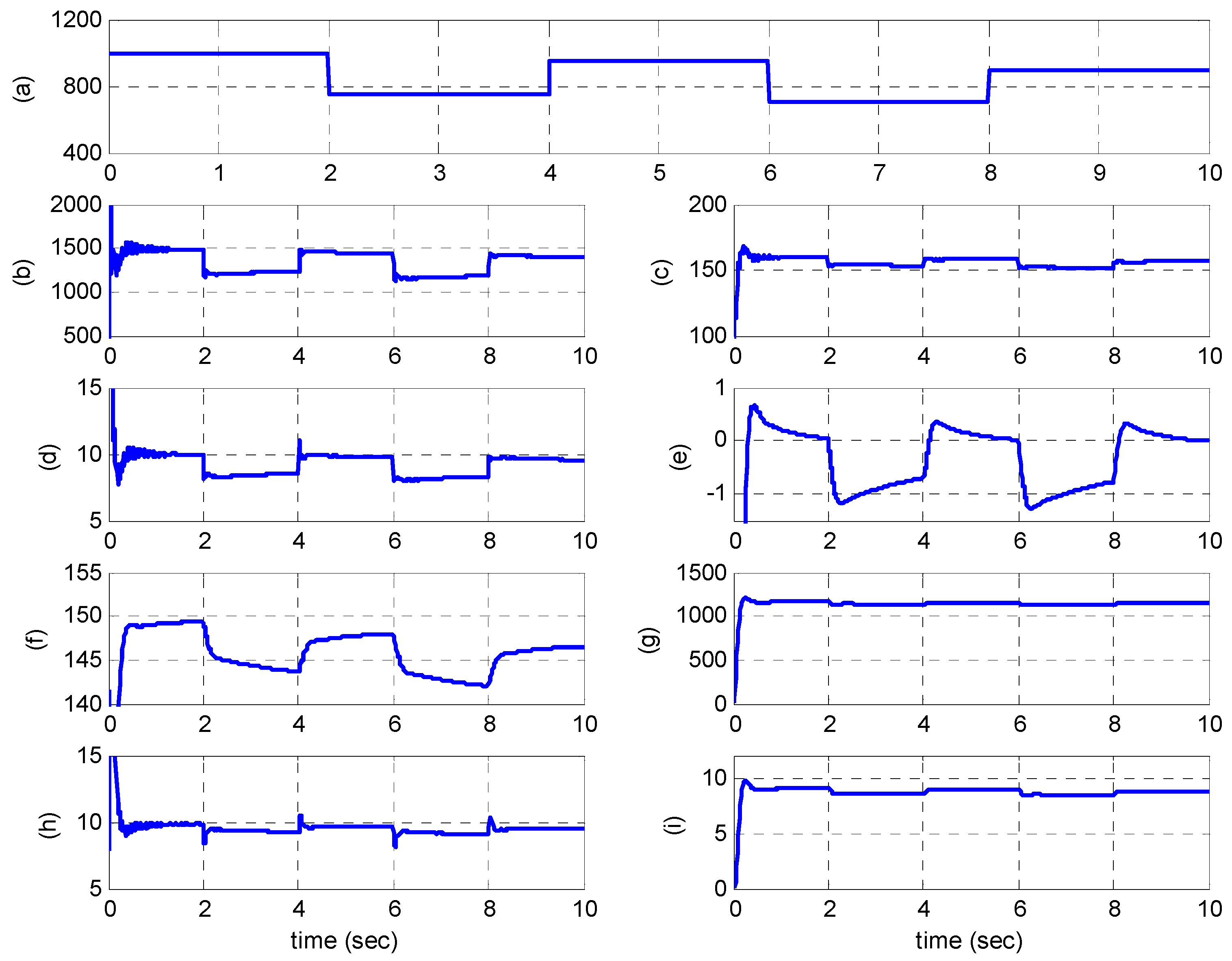
In this case it is proposed that the PV/battery storage system is operated without MPPT conditions and supplying a DC motor pump load only. The performance of the proposed system has been tested with a step change in solar insolation level. Thus, the solar insolation level is assumed to vary abruptly between 700 W/m2 and 1000 W/m2 as shown in Figure 5a. Figure 5b–i illustrate the dynamic responses of the PV output power, PV output voltage, PV output current, battery current, battery voltage, DC motor rotor speed, DC motor current and DC motor torque respectively based on the proposed optimal controller.
It can be noticed in Figure 5a–i that as the solar insolation level increases, the power output of the PV-generator will increase, and the duty ratio will increase to increase the DC/DC converter output power. The battery will charge in this case and the battery voltage will increase. Increasing of the battery current will maintain the DC motor constant and hence the motor speed and torque. That’s mean existing of the battery will consume the extra power and the motor will continue operation at constant speed. Vice versa if the solar insolation level decreases, the battery in this case will discharge as shown in Figure 5e,f while the motor will keep operating at constant rotor speed and constant motor current as shown in Figure 5g,h, respectively.
7.2. Case 2
In this case it is proposed that the PV/battery storage system is operated under MPPT conditions and also supplying in this case a DC motor pump load only. The system responses based on the proposed controller and with applying MPPT are shown in Figure 6. As in case one the reference power is the maximum power that can be extracted from the PV generator for any isolation level.
Figure 5 and Figure 6 show that operating the system with MPPT will increase the generated power, whereby the power generated and absorbed by both the DC motor and the battery will increase more in the MPPT condition case than the case without MPPT condition. That is leads to an increase in DC motor rotor speed. From these figures we can notice that at G = 1000 in the case of MPPT, the PV output power is about 2122 W and the motor speed is about 1219 rpm, while the power generated and the motor rotor speed in the case MPPT is not used and under the same conditions are about 1475.5 W and 1157 rpm, respectively, as shown in Table 3.
Table 3 shows the power and motor rotor speed with and without using MPPT at different isolation level values. Based on this Table, the power can be increased by 43% in case of using MPPT than the case of not using MPPT. The simulation results also show that a motor can be supplied from a PV-generator with the maximum available power, which is needed by the load.
7.3. Case 3
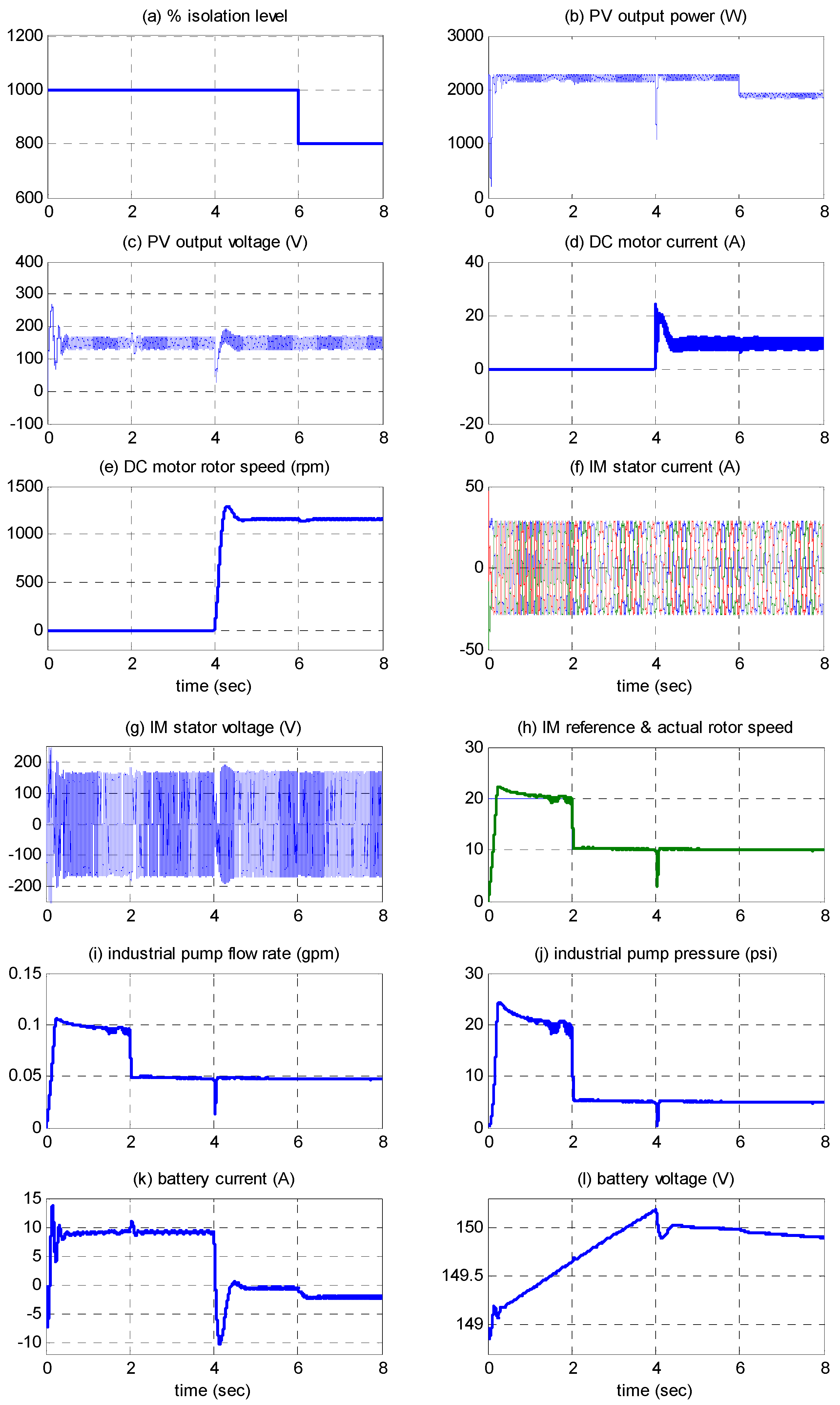
In this case it is proposed that the PV/battery storage system is operated under MPPT conditions and supplies an IM-industrial pump and a DC motor-water pump load. At first it is proposed the PV/storage system is supplying the IM-industrial pump only. After four seconds, it is proposed that the system is supplying both the DC motor-pump and the IM-industrial pump system. The dynamic responses are shown in Figure 7a–l, which show that:
- -
- when the isolation level decrease from 1000 to 800, the PV output power decreases from 2200 W to 1950 W and the battery current increases from a discharging current of 1 A to a discharging current of 2.5 A as shown in Figure 7a,b,k, respectively.
- -
- Varying the IM rotor speed affects the motor stator current and voltage frequency and the industrial pump flow rate and pressure as shown in Figure 7f,g,i,j, respectively.
- -
- Operating the DC motor pump system at time 4 seconds forces the current of the battery to vary from charging 9 A to 1 A discharging as shown in Figure 7k.
Based on the above cases, we can note that the proposed PV/storage system with the proposed controllers can operate the suggested dynamic loads individually or together and supplying them with needed power in their reference voltages and with good performance.
8. Conclusions
In this study, increasing the efficiency of a hybrid PV/energy storage system powering dynamic loads is depicted and investigated. Both the PV output power and the battery charge/discharge modes are managed and controlled based on optimal PID control. The artificial bee colony optimization approach is used to tune and optimize the PID controller parameters. The main contribution of this manuscript is the guarantee of supplying continuous power to stand-alone dynamic load and with high efficiency.
An optimal PID control is applied to control the PV generator in case of normal operation or in case of MPPT and to also control the battery storage charge/discharge modes. The IM rotor speed is regulated using a vector control based on the proposed optimal control to meet the industrial pump performance. The digital simulation results show that operating the proposed hybrid PV/energy storage system in case of MPPT techniques adds about 43% more extra power than in case of normal conditions. Also, the system can be managed to operate both the DC motor and the IM at the time the maximum power is available.
Author Contributions
Ibrahem E. Atawi obtained the proposed system mathematical model. Ahmed M. Kassem performed the model in MATLAB/SIMULINK software and designed the controller. Then both Ibrahem E. Atawi and Ahmed M. Kassem have obtained the results, written and reviewed the article.
Conflicts of Interest
The authors declare no conflict of interest.
Abbreviations
| PV generator output voltage | |
| PV generator current | |
| Insolation photo current of the PV generator | |
| PV generator reverse saturation current | |
| PV generator series resistance | |
| DC motor armature voltage | |
| DC motor armature current | |
| Armature resistance | |
| Rotor shaft speed of the DC motor. | |
| Back emf voltage of the DC motor. | |
| Torque constant of the DC motor. | |
| back emf constant of the DC motor. | |
| friction coefficient of the DC motor. | |
| moment of inertia of the DC motor. | |
| Load torque on the DC motor. | |
| Load torque constant on the DC motor. | |
| D | Duty ratio of the DC/DC converter. |
| Insolation level | |
| DC Motor friction | |
| DC motor Load friction | |
| Torque & back emf constant | |
| ξ | Load torque constant |
References
- Takagi, M.; Iwafune, Y.; Yamaji, K.; Yamamoto, H.; Okano, K.; Hiwatari, R.; Ikeya, T. Economic Value of PV Energy Storage Using Batteries of Battery-Switch Stations. IEEE Trans. Sustain. Energy 2013, 4, 164–173. [Google Scholar] [CrossRef]
- Eymour, H.R.; Sutanto, D.; Muttaqi, K.M.; Ciufo, P. Solar PV and Battery Storage Integration using a New Configuration of a Three-Level NPC Inverter with Advanced Control Strategy. IEEE Trans. Energy Convers. 2014, 29, 354–365. [Google Scholar]
- Karavas, C.S.; Kyriakarakos, G.; Arvanitis, K.G.; Papadakis, G. A multi-agent decentralized energy management system based on distributed intelligence for the design and control of autonomous poly generation micro grids. Energy Convers. Manag. 2015, 103, 166–179. [Google Scholar] [CrossRef]
- Kyriakarakos, G.; Dounis, A.I.; Rozakis, S.; Arvanitis, K.G.; Papadakis, G. Polygeneration microgrids: A viable solution in remote areas for supplying power, potable water and hydrogen as transportation fuel. Appl. Energy 2011, 88, 4517–4526. [Google Scholar] [CrossRef]
- Von Appen, J.; Stetz, T.; Braun, M.; Schmiegel, A. Local Voltage Control Strategies for PV Storage Systems in Distribution Grids. IEEE Trans. Smart Grid 2014, 5, 1002–1009. [Google Scholar] [CrossRef]
- Adhikari, S.; Fangxing, L. Coordinated V-f and P-Q Control of Solar Photovoltaic Generators with MPPT and Battery Storage in Microgrids. IEEE Trans. Smart Grid 2014, 5, 1270–1281. [Google Scholar] [CrossRef]
- Renaudineau, H.; Donatantonio, F.; Fontchastagner, J.; Petrone, G.; Spagnuolo, G.; Martin, J.-P.; Pierfederici, S. A PSO-Based Global MPPT Technique for Distributed PV Power Generation. IEEE Trans. Ind. Electron. 2015, 65, 1047–1058. [Google Scholar] [CrossRef]
- Oshiro, M.; Tanaka, K.; Senjyu, T.; Toma, S.; Yona, A.; Saber, A.Y.; Funabashi, T.; Kim, C. Optimal voltage control in distribution systems using PV generators. Int. J. Electr. Power Energy Syst. 2011, 33, 485–492. [Google Scholar] [CrossRef]
- Mazouz, N.; Midoun, A. Control of a DC/DC converter by fuzzy controller for a solar pumping system. Int. J. Electr. Power Energy Syst. 2011, 33, 1623–1630. [Google Scholar] [CrossRef]
- Salah, C.B.; Ouali, M. Comparison of fuzzy logic and neural network in maximum power point tracker for PV systems. Electr. Power Syst. Res. 2011, 81, 43–50. [Google Scholar] [CrossRef]
- Liu, Y.-H.; Liu, C.; Huang, J.; Chen, J. Neural-network-based maximum power point tracking methods for photovoltaic systems operating under fast changing environments. Sol. Energy 2013, 89, 42–53. [Google Scholar] [CrossRef]
- Bilal, B. Implementation of artificial bee colony algorithm on maximum power point tracking for pv modules. In Proceedings of the IEEE 8th International Symposium on Advanced Topics in Electrical Engineering (ATEE), Bucharest, Romania, 23–25 May 2013; pp. 1–4. [Google Scholar]
- Kassem, A.M. Modelling and robust control design of a standalone wind-based energy storage generation unit powering an induction motor variable-displacement pressure compensated pump. IET Renew. Power Gener. 2016, 10, 275–286. [Google Scholar] [CrossRef]
- Johan, N.F.M.; Azmi, A.; Rashid, M.A.; Yaakob, S.B.; Rahim, S.R.A.; Zali, S.M. Multi-Objective Using Artificial Bee Colony Optimization For Distributed Generation Placement On Power System. In Proceedings of the IEEE International Conference on Control System, Computing and Engineering (ICCSCE), Minden, Malaysia, 29 November–1 December 2013; pp. 117–121. [Google Scholar]
- Abu-Mouti, F.S.; El-Hawary, M.E. Optimal Distributed Generation Allocation and Sizing in Distribution Systems via Artificial Bee Colony Algorithm. IEEE Trans. Power Deliv. 2011, 26, 2090–2101. [Google Scholar] [CrossRef]
- De, M.; Goswami, S.K. Optimal Reactive Power Procurement with Voltage Stability Consideration in Deregulated Power System. IEEE Trans. Power Syst. 2014, 29, 2078–2086. [Google Scholar] [CrossRef]
- Sundareswaran, K.; Sankar, P.; Nayak, P.S.R.; Simon, S.P.; Palani, S. Enhanced Energy Output From a PV System Under Partial Shaded Conditions Through Artificial Bee Colony. IEEE Trans. Sustain. Energy 2015, 6, 198–209. [Google Scholar] [CrossRef]
- Javadi, M.R.; Jalilvand, A.; Noroozian, R.; Valizadeh, M. Optimal Design and Economic Assessment of Battery Based Stand-Alone Wind/PV Generating System Using ABC. In Proceedings of the IEEE Proceedings of the 3rd Conference on Thermal Power Plants (CTPP), Tehran, Iran, 18–19 October 2011; pp. 1–7. [Google Scholar]
- Hussein, A.; Hirasawa, K.; Hu, J. A robust control method for a PV-supplied DC motor using universal learning networks. Sol. Energy 2004, 76, 771–780. [Google Scholar] [CrossRef]
- Kassem, A.M.; Zaid, S.A. Load parameter waveforms improvement of a standalone wind-based energy storage system and Takagi–Sugeno fuzzy logic algorithm. IET Renew. Power Gener. 2014, 8, 775–785. [Google Scholar] [CrossRef]
- Swierczynski, M.; Teodorescu, R.; Rasmussen, C.N.; Rodriguez, P.; Vikelgaard, H. Overview of the Energy Storage Systems for Wind Power Integration Enhancement. In Proceedings of the IEEE ISIE, Bari, Italy, 4–7 July 2010; pp. 3749–3756. [Google Scholar]
- Adly, M.; Besheer, A.H. A meta-heuristics search algorithm as a solution for energy transfer maximization in stand-alone photovoltaic systems. Int. J. Electr. Power Energy Syst. 2013, 51, 243–254. [Google Scholar] [CrossRef]
- El-Fergany, A.A.; Abdelaziz, A.Y. Capacitor placement for net saving maximization and system stability enhancement in distribution networks using artificial bee colony-based approach. Int. J. Electr. Power Energy Syst. 2014, 54, 235–243. [Google Scholar] [CrossRef]
Figure 1.
Schematic diagram of the proposed stand-alone PV/storage/dynamic load system.

Figure 2.
Boost-converter (a) circuit diagram; (b) controller block diagram.

Figure 3.
Induction motor-bump system block diagram controlled based on vector control.
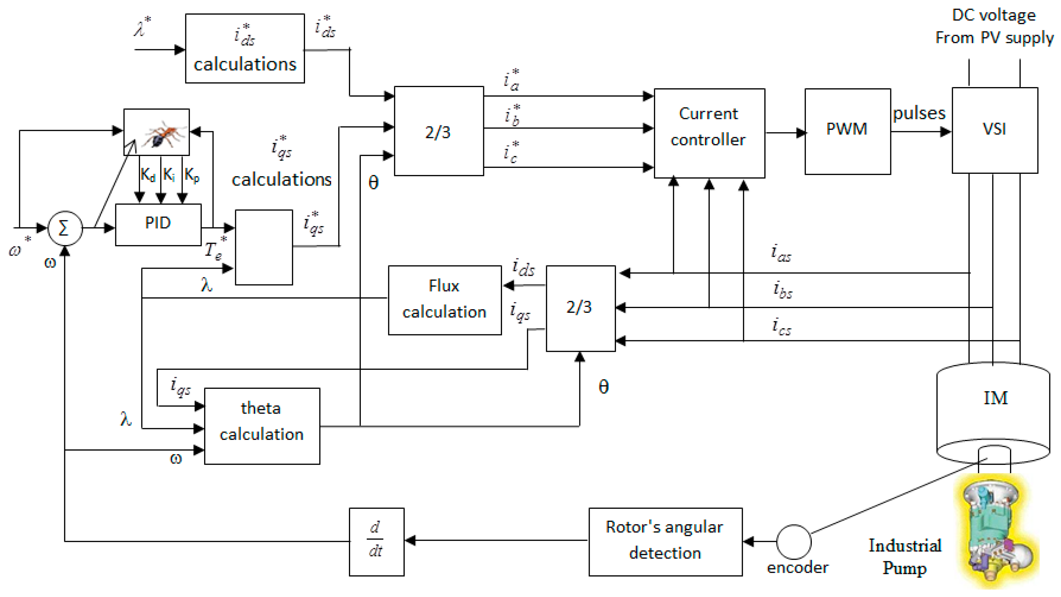
Figure 4.
Schematic diagram of the autonomous hybrid PV/battery storage energy conversion unit powering a DC motor-pump and IM-industrial pump loads with proposed control system.
Figure 4.
Schematic diagram of the autonomous hybrid PV/battery storage energy conversion unit powering a DC motor-pump and IM-industrial pump loads with proposed control system.
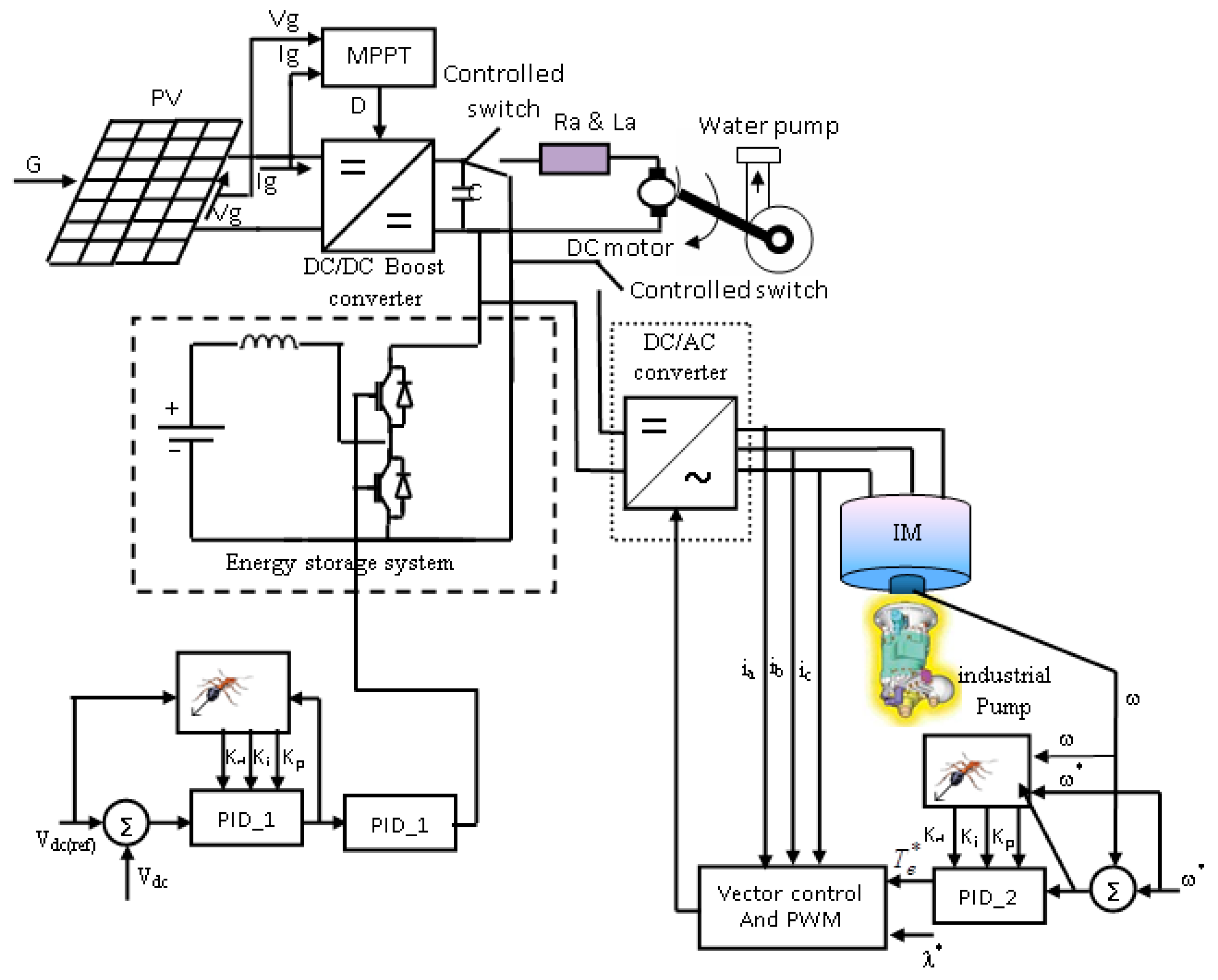
Figure 5.
Case (1), the system performance based on proposed controller, DC motor pump load only and without MPPT: (a) % isolation level, G; (b) PV output power (W); (c) PV output current (A); (d) PV output voltage (V); (e) battery current (A); (f) battery voltage (V); (g) DC motor rotor speed (rpm); (h) DC motor current (A); and (i) DC motor torque (Nm).

Figure 6.
Case (2), the system performance based on proposed controller, DC motor pump load only and with MPPT: (a) % isolation level, G; (b) PV output power (W); (c) PV output current (A); (d) PV output voltage (V); (e) battery current (A); (f) battery voltage (V); (g) DC motor rotor speed (rpm); (h) DC motor current (A); and (i) DC motor torque (Nm).
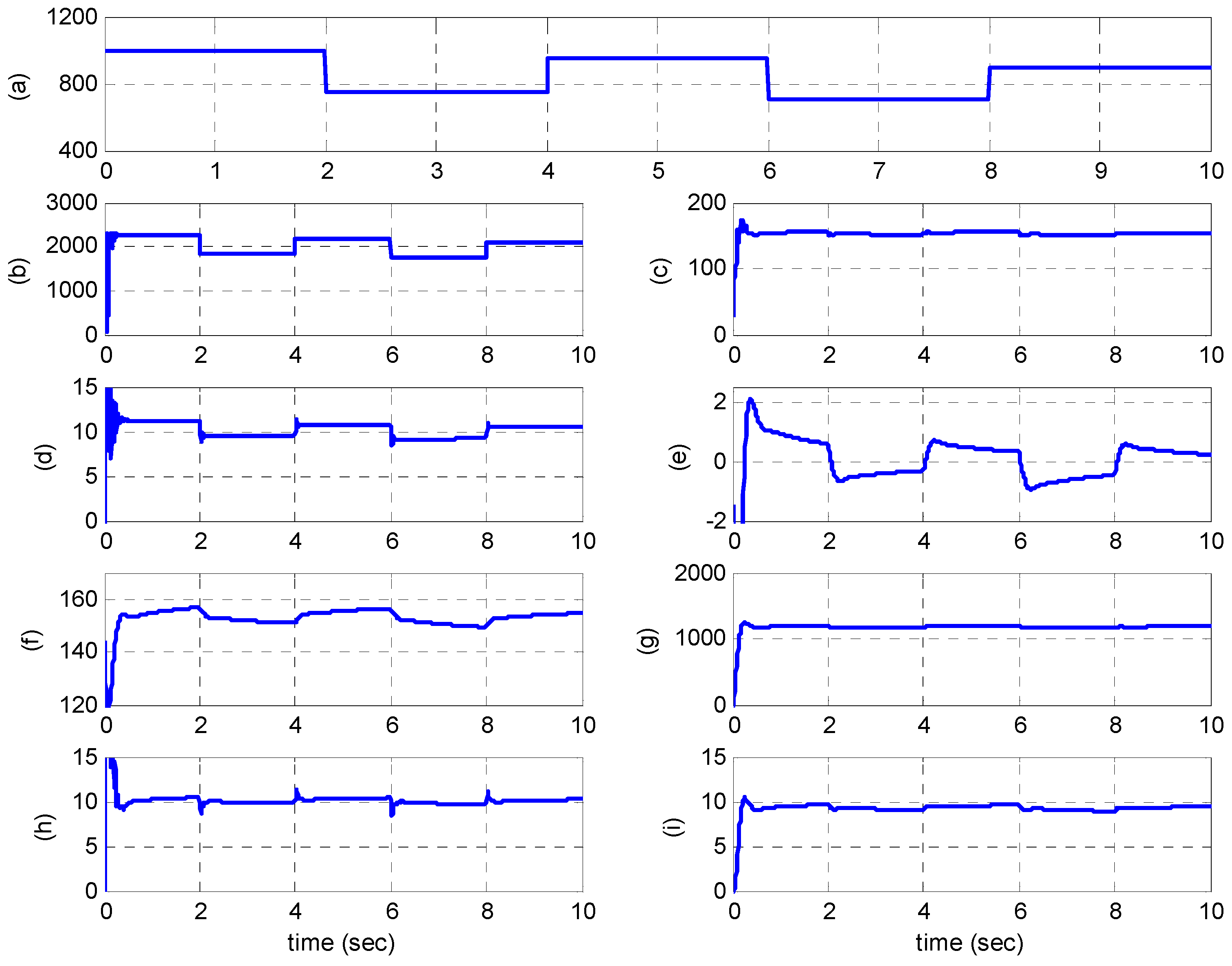
Figure 7.
Case (3), the system performance supplying both DC motor-water pump and IM-industrial pump based on MPPT and proposed controllers. (a) % isolation level, G; (b) PV output power (W); (c) PV output voltage (V); (d) PV output current (A); (e) DC motor rotor speed (rpm); (f) IM stator current (A); (g) IM stator voltage (V); (h) IM reference and actual rotor speed (rad/sec); (i) industrial pump flow rate (gpm); (j) industrial pump pressure (psi); (k) battery current (A); and (l) battery voltage (V).


Table 1.
PV parameters.
| Variable | Value |
|---|---|
| Q | 1.602 × 10⁻¹⁹ C |
| Z | 1.38 × 10⁻²³ J/K |
| U | 298.15 °C |
| ε | 1.1 |
| Ns | 460 |
| Np | 15 |
| Rs | 0.0152 Ω |
| Iph | 4.8 A |
| Io | 2.58 × 10⁻⁵ A |
| Rated Power | 2.5 KW |
Table 2.
Control parameters adopted for the ABC algorithm.
| Item | Proposed Setting |
|---|---|
| The colony size | 70 |
| Food Number | 35 |
| Limit | 150 |
| Max Cycle | 2000 |
Table 3.
The system output data.
| Item | G = 1000 | G = 700 | ||
|---|---|---|---|---|
| With MPPT | Without MPPT | With MPPT | Without MPPT | |
| PV output power (W) | 2122 | 1475.4 | 1652 | 1157.2 |
| PV output voltage(V) | 160 | 149.68 | 154 | 143.2 |
| PV output current (A) | 11.73 | 8.4 | 9.67 | 8.14 |
| Battery current (A) | 0.84 | 0.16 | −0.36 | −0.78 |
| Motor current (A) | 10.725 | 8.22 | 10.09 | 7.34 |
| Motor speed (rpm) | 1219 | 1157 | 1203.5 | 1114 |
© 2017 by the authors. Licensee MDPI, Basel, Switzerland. This article is an open access article distributed under the terms and conditions of the Creative Commons Attribution (CC BY) license (http://creativecommons.org/licenses/by/4.0/).
Share and Cite
MDPI and ACS Style
Atawi, I.E.; Kassem, A.M. Optimal Control Based on Maximum Power Point Tracking (MPPT) of an Autonomous Hybrid Photovoltaic/Storage System in Micro Grid Applications. Energies 2017, 10, 643. https://doi.org/10.3390/en10050643
AMA Style
Atawi IE, Kassem AM. Optimal Control Based on Maximum Power Point Tracking (MPPT) of an Autonomous Hybrid Photovoltaic/Storage System in Micro Grid Applications. Energies. 2017; 10(5):643. https://doi.org/10.3390/en10050643
Chicago/Turabian StyleAtawi, Ibrahem E., and Ahmed M. Kassem. 2017. "Optimal Control Based on Maximum Power Point Tracking (MPPT) of an Autonomous Hybrid Photovoltaic/Storage System in Micro Grid Applications" Energies 10, no. 5: 643. https://doi.org/10.3390/en10050643
Note that from the first issue of 2016, this journal uses article numbers instead of page numbers. See further details here.