
A Battery Power Bank with Series-Connected Buck–Boost-Type Battery Power Modules


1
Department of Electrical Engineering, National Sun Yat-sen University, 70 Lienhai Rd., Kaohsiung 80424, Taiwan
2
Realtek Semiconductor Corporation, 2 Innovation Rd. II, Hsinchu Science Park, Hsinchu 300, Taiwan
*
Author to whom correspondence should be addressed.
Energies 2017, 10(5), 650; https://doi.org/10.3390/en10050650
Submission received: 14 March 2017
/
Revised: 18 April 2017
/
Accepted: 2 May 2017
/
Published: 8 May 2017
Abstract
:The operation of a battery power bank with series-connected buck–boost-type battery power modules (BPMs) was investigated in this study. Each BPM consisted of a battery pack with an associated buck–boost converter for individually controlling battery currents. With a proposed discharging scenario, load voltage regulation with charge equalization among batteries was performed by controlling the battery currents in accordance with their state-of-charges (SOCs) estimated by real-time battery-loaded voltages detected under the same operating condition. In addition, the fault tolerance was executed to isolate exhausted or faulty batteries from the battery power bank without interrupting the system operation. Experiments were conducted to verify the effectiveness of the discharging scenario for a laboratory battery power bank with four series buck–boost BPMs.
1. Introduction
In the last two decades, the operating performances and the lifespan of the rechargeable battery have been significantly improved due to the growing advancements in battery materials and technologies. This has facilitated high-power applications such as electrical vehicles (EVs) and energy storage buffers in electrical power grids [1,2,3]. Since a battery cell voltage is too low for most applications, in practice, a number of cells are series-connected to supply a high enough voltage. One of the most important processes during manufacturing is to sort the newly formatted cells by their maximum usable capacity, internal impedance, and open-circuit voltage to ensure consistency in their operating characteristics [4,5]. However, there is some discrepancy among batteries since a compromise has to be made between the consistency and the manufacturing cost. Therefore, the divergence among cells or battery packs may still be enlarged after cyclic charging and discharging processes, causing problematic charge imbalance and leading to overcharging or overdischarging in some batteries [6].
Conventionally, a battery management system (BMS) with an additional charge equalizer is needed to mitigate the inconsistency among the state-of-charges (SOCs) of the batteries, which are grouped into a battery power bank [7,8,9]. The additional BMS and charge equalization circuits bring an additional production cost and greater energy losses. Alternatively, the concept of modular battery power, whereby each cell or single-packed battery is equipped with an associated power electronic converter to be a battery power module (BPM), has been presented to cope with this issue [10]. With such a modular configuration, battery currents can be controlled individually, facilitating battery management with SOC estimation and state-of-health (SOH) evaluation. A battery power bank can be formed by a number of BPMs connected in series or parallel for aggregating higher voltage, power, and energy. With a bidirectional converter, charge equalization can be made during either charging or discharging phases [11,12,13]. A charging scenario based on a constant-current/constant-voltage (CC-CV) scheme has been proposed for the parallel buck–boost BPMs to fully utilize the available power provided by the dc source, which means that the entire charging process can be more efficient [12]. During the charging process, the battery charging currents are regulated in accordance with their ongoing SOCs accumulated by the coulomb counting method for alleviating the charge imbalance among batteries. The discharging operation of the buck–boost-type BPMs with series output in the continuous conduction mode (CCM) and the discontinuous conduction mode (DCM) was analyzed in [13], in which a much higher output voltage was obtained by boost conversion as well as by series configuration. The effectiveness of performing charge equalization with BPMs has thus been preliminarily verified in these works.
This paper focuses on the discharging operation of a battery power bank with bidirectional buck–boost-type BPMs connected in series. A buck–boost converter was able to isolate the exhausted or abnormal battery from the BPM by simply removing the gate signal to the corresponding active power switch without the need for additional devices [12]. A laboratory battery power bank is set up with a proposed discharging scenario to demonstrate the performances of charge equalization, load voltage regulation, and fault tolerance with experimental results.
2. The Battery Power Bank
Figure 1 illustrates a battery power bank formed by n-series buck–boost-type BPMs, where the subscript “i” denotes the i-th BPM in the bank. Each BPM consists of an adequately rated battery set and an associated buck–boost converter. The series buck–boost BPMs can regulate the output voltage in a wide range, which can be either higher or lower than the sum of terminal voltages of the battery sets. During the discharging process, the active power switch denoted by SBi at the battery side is the main switch for the buck–boost conversion, while the active power switch at the load side, SCi, performs the synchronous rectification conducting the freewheeling current of the inductor. To prevent a recharging current, SCi is turned off as the freewheeling current deceases to zero.
With such a modular configuration, a battery power bank can be fabricated with an adequate number of series BPMs for collaboratively outputting an aggregated voltage and current to fulfill the load requirement of high voltage. Since the BPMs can be individually controlled, the discharging scenario can be programmed in a more flexible manner without substantial modifications on the converters. All BPMs in the battery power bank are operated with an equally shifted phase at the same switching frequency, as illustrated in Figure 2. For a battery power bank configured with n-series BPMs, the output voltage ripple can be mitigated nearly to 1/n with n times the switching frequency of the converter.
3. Circuit Operation
Due to the modular configuration of the battery power bank, the currents outputted by battery sets can be independently controlled even though the BPMs are connected in series. All working BPMs operate together to sustain the required load. During the discharging process, the output voltages of BPMs may differ from one another due to the different battery-loaded voltages and corresponding duty ratios. Then, the average output voltage of the battery power bank, Vo, is obtained by adding up the average output voltages of BPMs:
where m represents the number of the working BPMs.
On the other hand, the average output currents of the BPMs are identical with the load current since their output capacitors are connected in series.
In practice, the buck–boost converters in BPMs may be operated at either the CCM or the DCM. When they are operated at the CCM, the relations between the average discharging currents and the duty ratios of the associated converters are
This equation indicates that a higher duty ratio to the corresponding converter draws the larger average current from the battery. In other words, the charge equalization can be achieved by regulating the duty ratios of BPMs in terms of their existing battery SOCs.
In the case that all BPMs are operated at DCM, the relationship among the average discharging currents of BPMs can be derived as
in which di′ denotes the ratio of the time that the inductor current declines from its peak to zero in a switching period. The relations among battery voltages can be expressed as
According to Equations (4) and (5), di′ is inversely proportional to the corresponding battery voltage and current, meaning that charge equalization can be accomplished simply by operating all BPMs with the same duty ratio at the DCM.
4. Balanced Discharging Scenario
In general, the battery SOCs can be estimated by their terminal voltages measured under the same operating condition. Figure 3 shows the battery-loaded voltage curves at different discharging currents. For a fully charged battery, the battery voltage declines rapidly at the early stage of the discharging process and then goes through a flat region for a wide range of the battery SOC. Thereafter, the battery voltage decreases drastically when it experiences first a knee point, Vk, and then the cut-off point, Vc. A battery is considered to be exhausted and has to be isolated when the battery voltage has been decreased to Vc. A larger discharging current results in a shorter discharging duration. With diverse discharging currents, the knee voltages can be slightly different from each other. In this research, the knee point voltage and the cut-off voltage are designated at 12.4 V and 10.0 V, respectively.
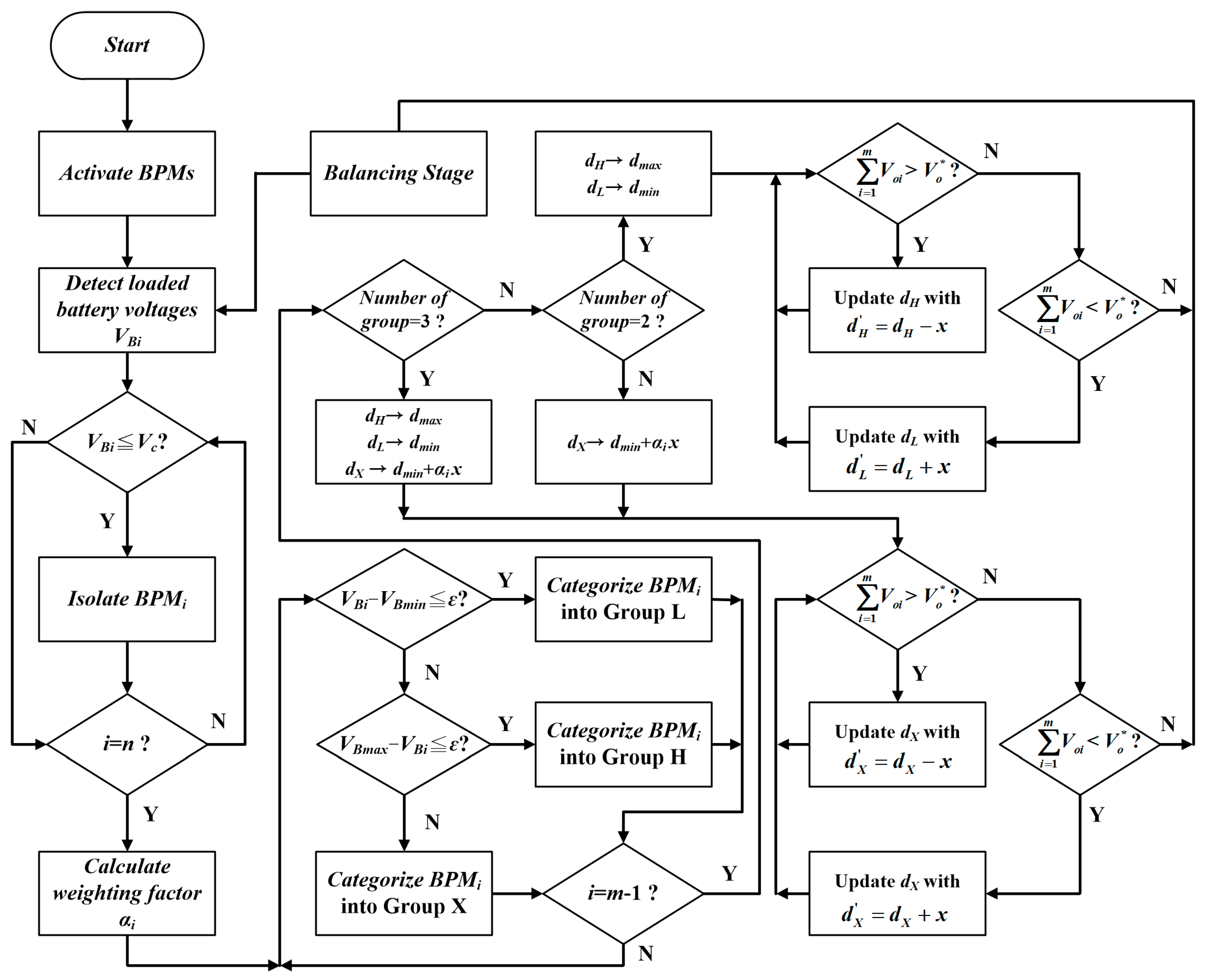
Figure 4 shows the control flowchart of the discharging scenario, aiming to perform charge equalization among batteries and at the same time regulate the load voltage. At first, all BPMs are first activated and then operated at the same duty ratio. In the detection stage, all batteries are discharged with an identical current for detecting the loaded battery voltages. Accordingly, a proportional factor, α, is designated for coordinating the discharging currents among the working BPMs.
where αi represents the ratio between the i-th battery’s average voltage, VBi, and the sum of the battery average voltages.
To properly schedule the discharging currents, all working BPMs are categorized into three groups in terms of their battery voltages, which are measured at the detection stage. Groups H and L stand for the BPMs with the highest and lowest battery voltages, respectively, and the remaining BPMs are in Group X. To accomplish charge equalization as soon as possible, the BPMs in Group H is operated at the maximum duty ratio, dmax, to supply more power than the others, whereas the batteries in Group L is drawn with the minimum current at the minimum duty ratio, dmin. The output voltage regulation is achieved by regulating the duty ratios of the BPMs in Group X, which are operated with factors proportional to the loaded voltages. When an output voltage is detected to be lower than the designated output voltage, , an increment is added to the corresponding duty ratios of the BPMs in Group X, dX. On the other hand, a decrement of duty ratio is for a higher output voltage. In the case that all working BPMs are categorized into Groups H and L, the output voltage regulation can be accomplished by decreasing or increasing the duty ratios to Groups H and L, depending on the difference between the detected voltage and the designated output voltage. As the discharging time elapses, the battery voltages become closer to each other. Eventually, all BPMs are in the same group, meaning that charge equalization among batteries has been accomplished. In this case, the load voltage regulation is executed by all working BPMs operating with the same duty ratio to fulfill the desired output voltage. Once a battery has been completely exhausted with a loaded voltage less than the cut-off voltage, the associated converter is stopped to isolate the battery from the battery power bank. The system stops when all working BPMs cannot sustain the load voltage.
Figure 5 illustrates the block diagram of the series buck–boost BPMs with peripheral control units, consisting of a digital signal processor (DSP), voltage sampling circuits, and gating circuits. Since the batteries are not grounded together, differential amplifiers are adopted in the voltage sampling circuits for galvanic isolation and at the same time for scaling the battery and the load voltages down to the signal levels for the DSP. The low-pass filters are added to eliminate the ripples on the sampled voltages. To execute the programmed discharging scenario with the latest sampled data, the DSP generates the gating signals to the BPMs to accomplish pulse-width modulation (PWM) with proportional control.
5. Fault Tolerance
For a battery power bank with a number of BPMs in series, all modules are operated cooperatively to fulfill the load requirements. In this way, the BPM with completely exhausted or damaged battery can be stopped without interrupting the system operation. The faulty battery is isolated from the battery power bank by simply removing the corresponding gate signal to the main power switch of the buck–boost converter. Figure 6 shows the current paths of an exemplar case when the battery in BPM2 has been isolated. Once SB2 has been turned off, SC2 is constantly turned on to reduce the additional conduction loss. At the beginning, the output capacitor of BPM2 is discharged by the load current. Eventually, the capacitor voltage is decreased to zero and the load current flows through the auxiliary power switch and the inductor. Subsequently, all the other working BPMs are operated with larger duty ratios to sustain the required load voltage and power.
6. Experimental Verifications
A battery power bank with four buck–boost BPMs is set up as shown in Figure 7. Each BPM is formed by a 4.6 Ah battery pack with an associated bidirectional buck–boost converter. The circuit parameters are listed in Table 1. The nominal voltage and the cut-off voltage of the battery pack are 13.6 V and 10.0 V, respectively. The BPM has to be stopped when the voltage of the associated battery declines to the cut-off point.
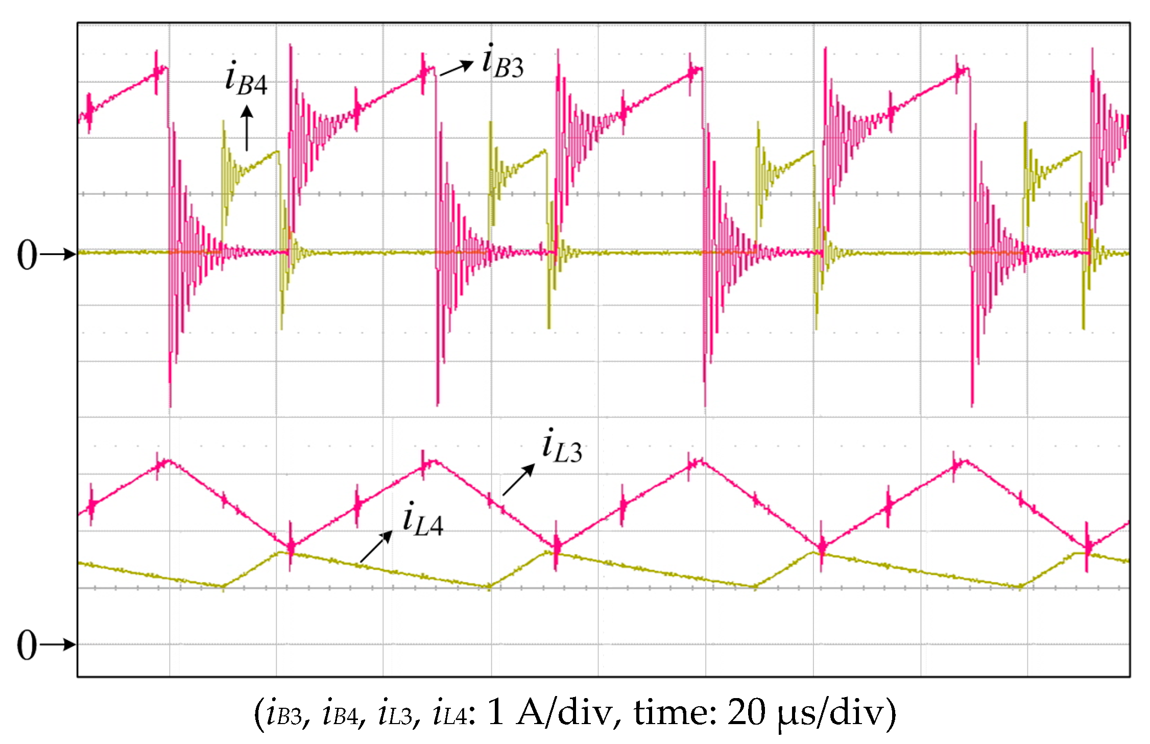
Figure 8 and Figure 9 show the measured battery and inductor currents in two modules, BPM3 and BPM4, during the detection stage and the balancing stage, respectively. In the tested case, the battery SOC of BPM4 is much lower than that of BPM3. During the detection stage, all BPMs are operated at the same duty ratio to draw an identical current from batteries with a shifted phase. During the balancing stage, the BPMs in Groups L and X are operated at duty ratios of 0.20 and 0.54, respectively. As a result, the battery B4 is discharged by a current much smaller than that of B3.
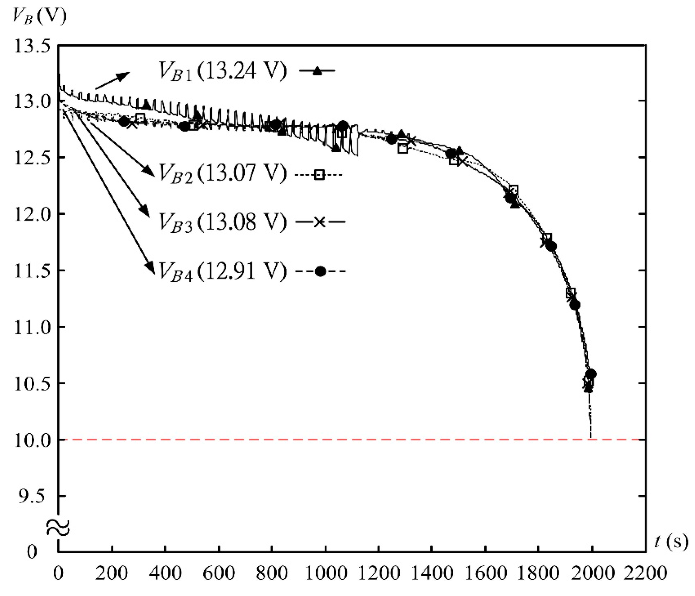
Figure 10 shows an experimental result of balanced discharging. Before the test, four batteries are deliberately set at different open-circuit voltages of 13.24 V, 13.07 V, 13.08 V, and 12.91 V, respectively. At the beginning, the battery in BPM4 stops discharging during the balancing stage. With a much smaller discharged current at the detection stage, the battery voltage decreases slightly.
After 530 s, the loaded voltages of BPM2 and BPM3 have declined to the same level as that for BPM4. Then, these three BPMs are operated with the same duty ratio smaller than that of BPM1. The output voltage is mostly contributed by BPM1. As a result, the battery voltage of BPM1 declines rapidly. At the 1310th second, all loaded battery voltages at the detection stage are identical to each other, and all BPMs are then operated with the same duty ratio. As the discharging time elapses, the voltage of B1 declines faster than the others due to the battery intrinsic discrepancy. Then, the duty ratio to SB1 is fine-tuned for fixing the unbalanced battery-loaded voltages at the 1715th second. As a result, all batteries reach the cut-off voltage at nearly the same time, meaning that charge equalization with balanced discharging has been accomplished.
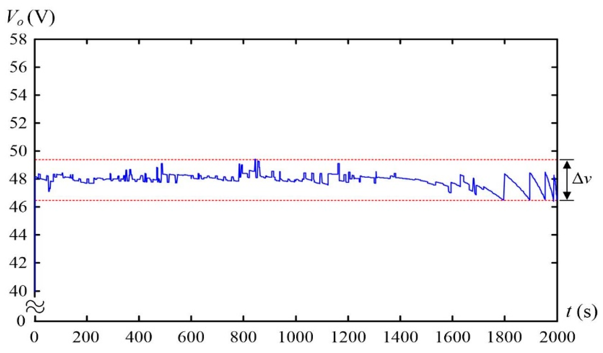
Figure 11 shows that the load voltage varies slightly in the process of discharging with output voltage regulation. The worst case happens at the end of the discharging process. In this case, all buck–boost converters are operated with high duty ratios to sustain the load requirements, resulting in the larger discharging currents and thus more voltage drops at the batteries’ voltages.
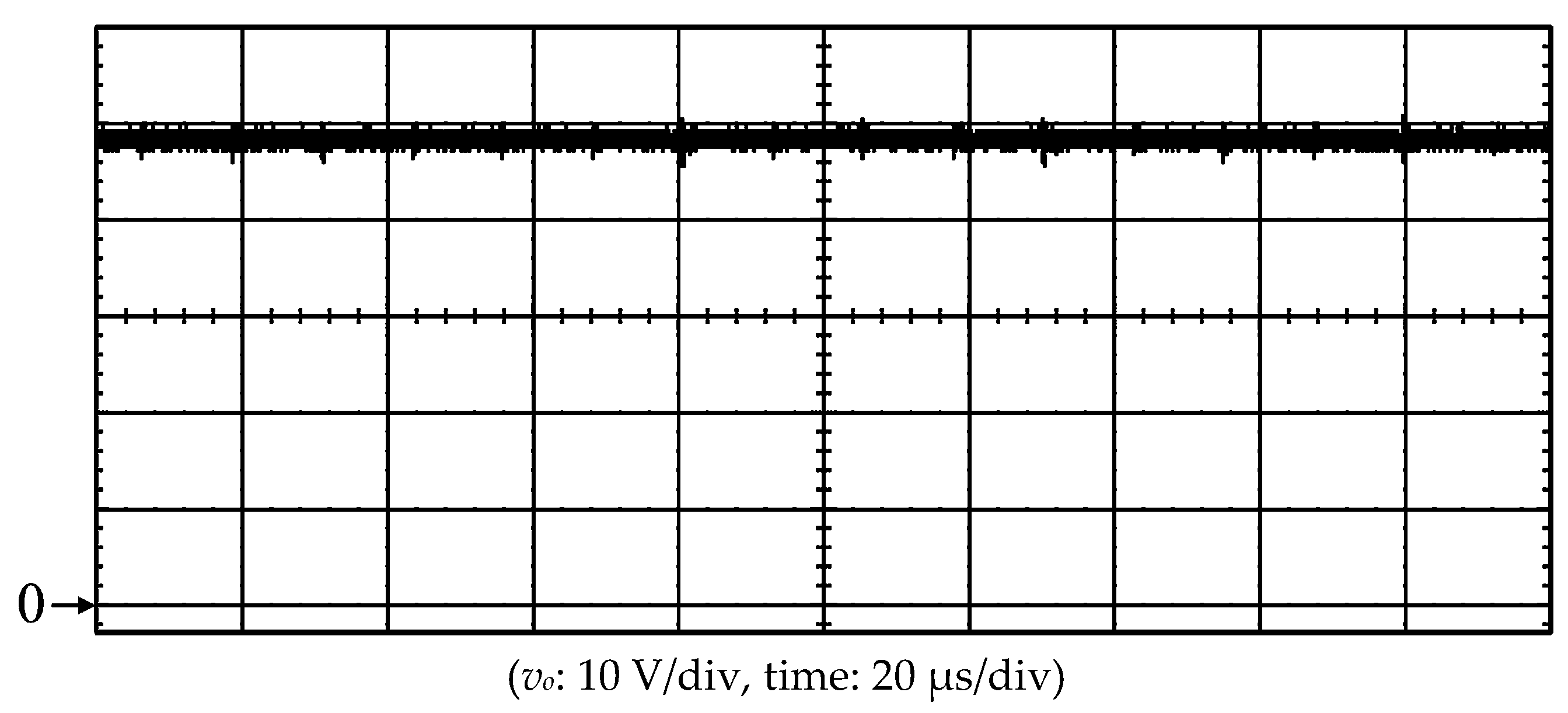
Figure 12 shows the switching spikes on the output voltage waveform when the battery power bank is loaded with an electronic load with a constant current. With equally phase-shifted operation, the frequency of the output voltage ripple is 80 kHz, which is four times the switching frequency of the buck–boost converter.
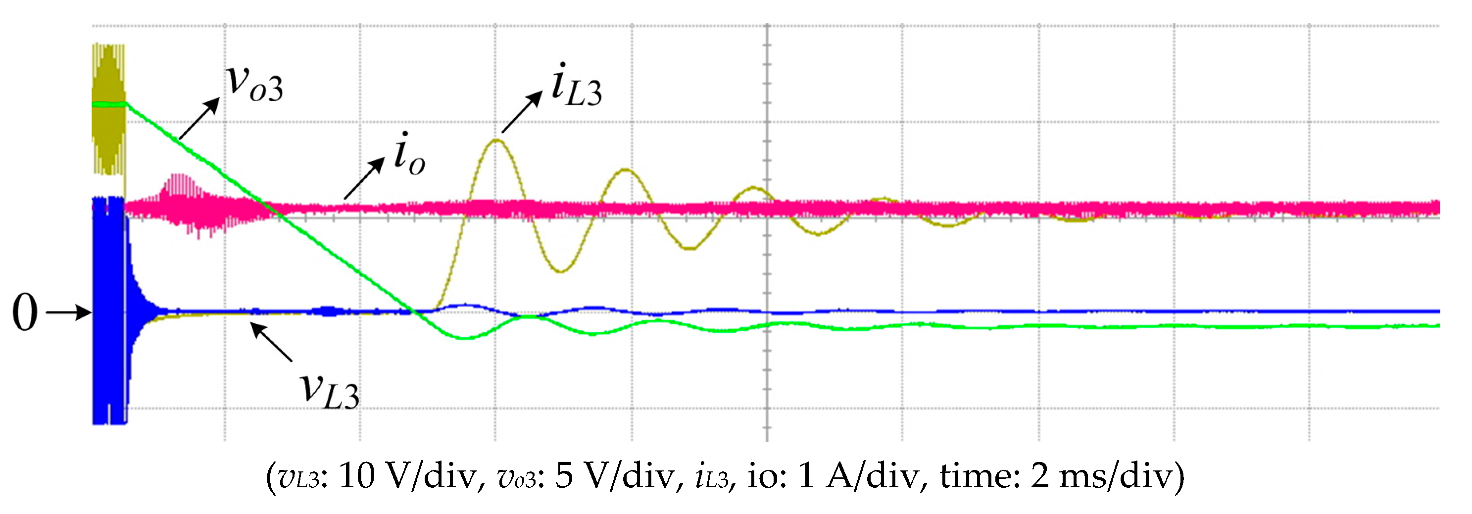
Figure 13 illustrates the isolating transient of BPM3 when its battery set has been completely exhausted, which stops a few seconds earlier than the others at the final stage of the discharging process. After SB3 has been switched off by removing the gate signal, the inductor current iL3 drops rapidly to zero, and the output filter capacitor Co3 is then discharged to supply the load current, causing decay on the output voltage of the BPM3. As vo3 gradually decreases to zero, the auxiliary power switch SC3 and the inductor L3 start to conduct the load current. An oscillation may occur between L3 and Co3. Eventually, L3 and SC3 form a path for conducting the output current. The oscillation lasts for a few milliseconds, causing a trivial effect to the battery power bank.
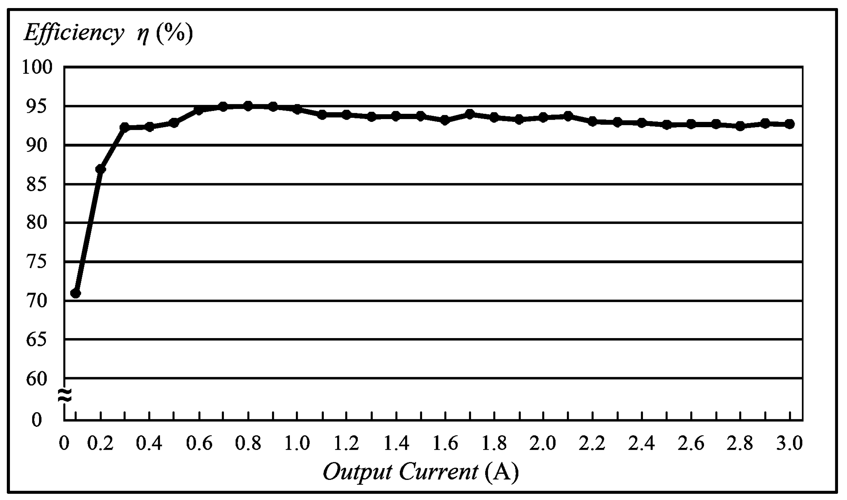
Figure 14 shows the measured efficiencies of the battery power bank. With such a series configuration, the inductor current of a BPM is branched into the capacitor current and the output current when its auxiliary power switch is turned on. The currents flowing through the equivalent series resistances (ESRs) of the output capacitors result in additional losses, leading to slight efficiency deterioration at the heavy load. In the experimental case, the average conversion efficiency is 93% throughout the discharging process.
7. Conclusions and Discussions
A battery power bank with series buck–boost-type BPMs has been proposed in this research to realize charge equalization, output voltage regulation, and fault tolerance. With associated buck–boost converters, the exhausted or damaged battery can be easily isolated simply by turning off the corresponding active power switch without the need of an extra mechanical switch. Moreover, the BPMs in the power bank can be individually controlled. A discharging scenario is programmed to execute charge equalization and load voltage regulation throughout the discharging process. With bidirectional BPMs, charge equalization can be made during either the charging or the discharging phase without any additional balancing circuit. This work is focused on the discharging operation since charge equalization can be achieved more easily for the charging phase since voltage regulation is not necessary. With the proposed discharging scenario, charge equalization can be accomplished before the end of the discharging. Therefore, the battery power can be utilized more efficiently. This can facilitate charge equalization for the following charge phase. In this research, the SOC estimation is made by detecting the loaded voltage under the same discharging current. The different SOC estimation algorithms as well as the discharging scenarios can be programmed without substantial modifications on BPMs for further improvements.
Acknowledgments
This work was supported by the Ministry of Science and Technology of Taiwan under the grant number of 105-2218-E-006-009.
Author Contributions
Chin-Sien Moo contributed to the conception of the study and English editing of the paper. Tsung-Hsi Wu performed the analysis of this work and wrote the paper under the supervision of Chin-Sien Moo. Tsung-Hsi Wu and Chih-Hao Hou conducted the experiments.
Conflicts of Interest
The authors declare no conflict of interest.
References
- Rodolfo, D.L.; José, L.B.A. Techno-economic analysis of grid-connected battery storage. J. Energy Convers. Manag. 2015, 91, 394–404. [Google Scholar]
- Einhorn, M.; Conte, F.V.; Kral, C.; Fleig, J. Comparison, selection, and parameterization of electrical battery models for automotive applications. IEEE Trans. Power Electr. 2013, 28, 1429–1437. [Google Scholar] [CrossRef]
- He, H.; Xiong, R.; Guo, H.; Li, S. Comparison study on the battery models used for the energy management of batteries in electric vehicles. J. Energy Convers. Manag. 2012, 64, 113–121. [Google Scholar] [CrossRef]
- Pei, L.; Wang, T.; Lu, R.; Zhu, C. Development of a voltage relaxation model for rapid open-circuit voltage prediction in lithium-ion batteries. J. Power Sources 2014, 253, 412–418. [Google Scholar] [CrossRef]
- Li, X.; Wang, T.; Pei, L.; Zhu, C.; Xu, B. A comparative study of sorting methods for lithium-ion batteries. In Proceedings of the IEEE Conference and Expo Transportation Electrification Asia-Pacific, Bejing, China, 31 August–3 September 2014. [Google Scholar]
- Kim, Y.; Samad, N.A.; Oh, K.Y.; Siegel, J.B.; Epureanu, B.I.; Stefanopoulou, A.G. Estimating state-of-charge imbalance of batteries using force measurements. In Proceedings of the American Control Conference, Boston, MA, USA, 6–8 July 2016. [Google Scholar]
- Rahimi-Eichi, H.; Ojha, U.; Baronti, F.; Chow, M.Y. Battery management system-an overview of its application in the smart grid and electric vehicles. IEEE Ind. Electr. Mag. 2013, 7, 4–16. [Google Scholar] [CrossRef]
- Xing, Y.; Ma, E.W.M.; Tsui, K.L.; Pecht, M. Battery management systems in electrical and hybrid vehicles. Energies 2011, 4, 1840–1857. [Google Scholar] [CrossRef]
- Baronti, F.; Roncella, R.; Saletti, R. Performance comparison of active balancing techniques for lithium-ion batteries. J. Power Sources 2014, 267, 603–609. [Google Scholar] [CrossRef]
- Moo, C.S.; Jian, J.Y.; Wu, T.H.; Yu, L.R.; Hua, C.C. Battery power system with arrayed battery power modules. Proceedings of IEEE International Conference on System Science and Engineering, Budapest, Hungary, 4–6 July 2013. [Google Scholar]
- Moo, C.S.; Ng, K.S.; Hsieh, Y.C. Parallel operation of battery power modules. IEEE Trans. Energy Convers. 2008, 23, 701–707. [Google Scholar]
- Wu, T.H.; Chang, C.S.; Moo, C.S. A charging scenario for parallel buck–boost battery power modules with full power utilization and charge equalization. In Proceedings of the IEEE International Conference on Industrial Technology, Seville, Spain, 17–19 March 2015. [Google Scholar]
- Moo, C.S.; Ng, K.S.; Hu, J.S. Operation of battery power modules with series output. In Proceedings of the IEEE International Conference on Industrial Technology, Churchill, Australia, 10–13 February 2009. [Google Scholar]
Figure 1.
Battery power bank with n-series battery power modules (BPMs).
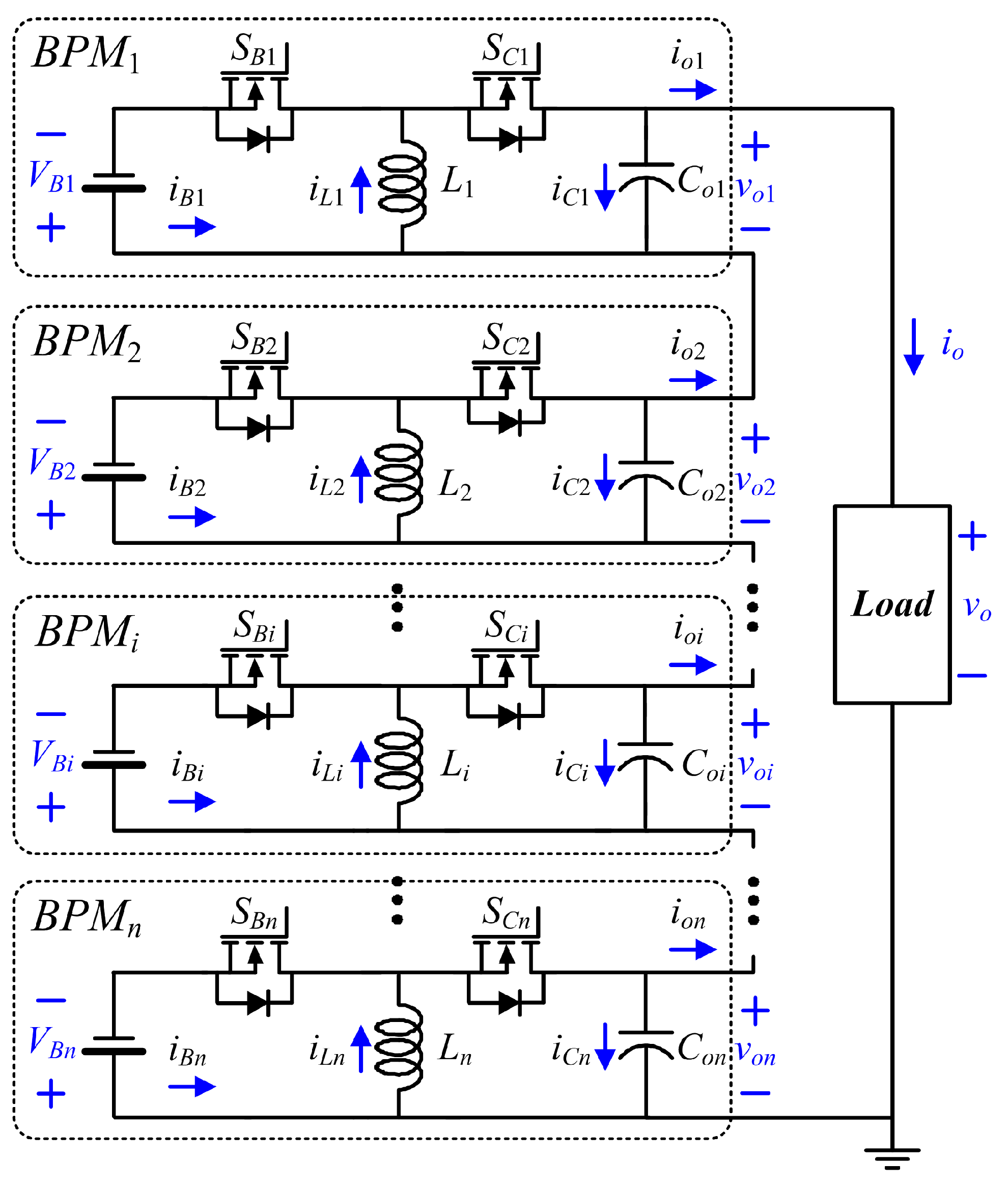
Figure 2.
Theoretical waveforms of BPMs with equal phase shift.
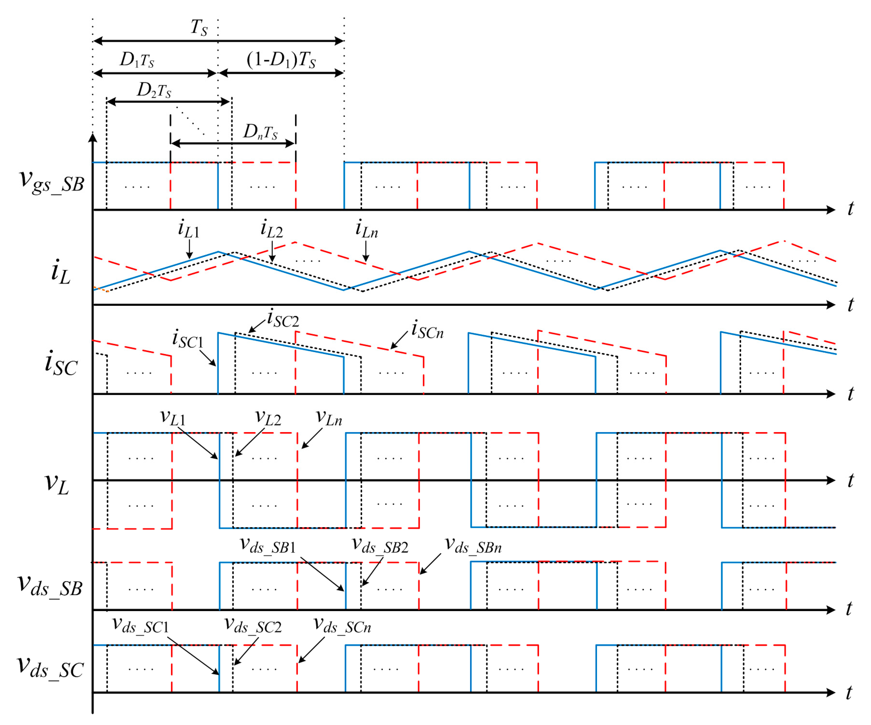
Figure 3.
Battery voltage curves with different discharging currents.
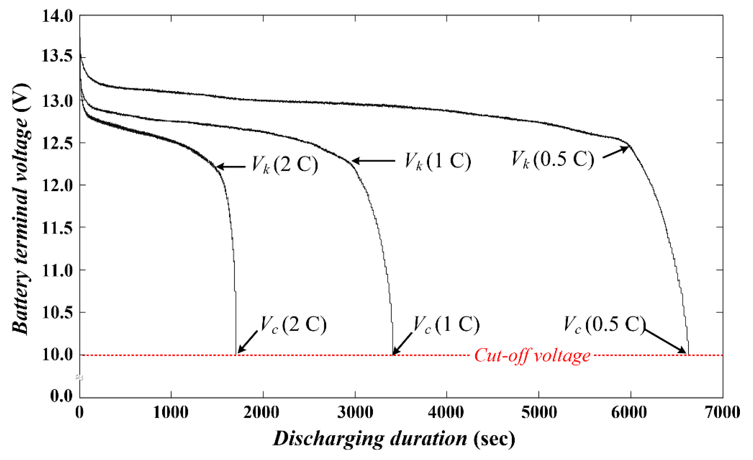
Figure 4.
Control flowchart of the discharging scenario.

Figure 5.
Series buck–boost BPMs with peripheral control units.
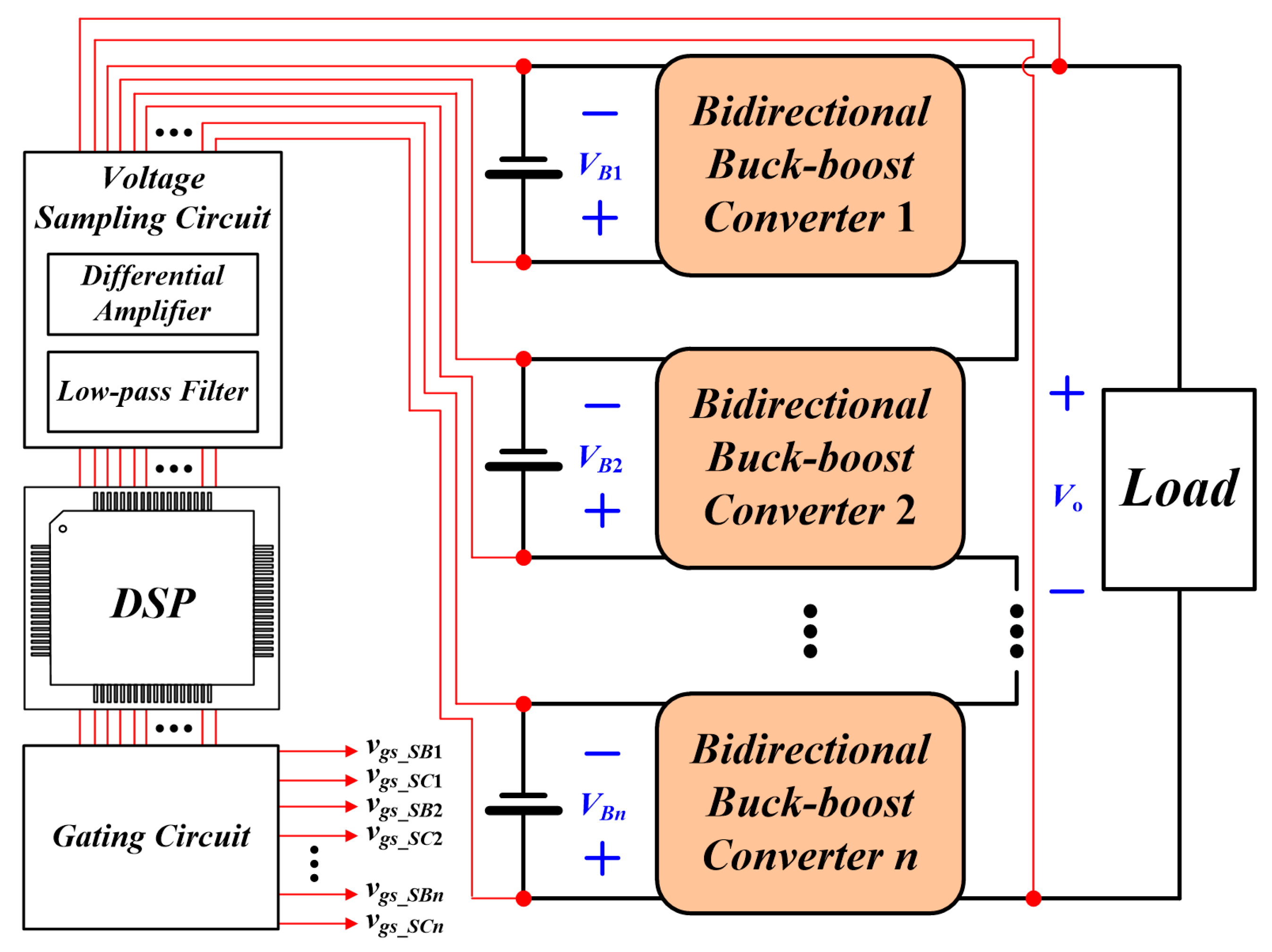
Figure 6.
Current path of series BPMs with an isolated battery.
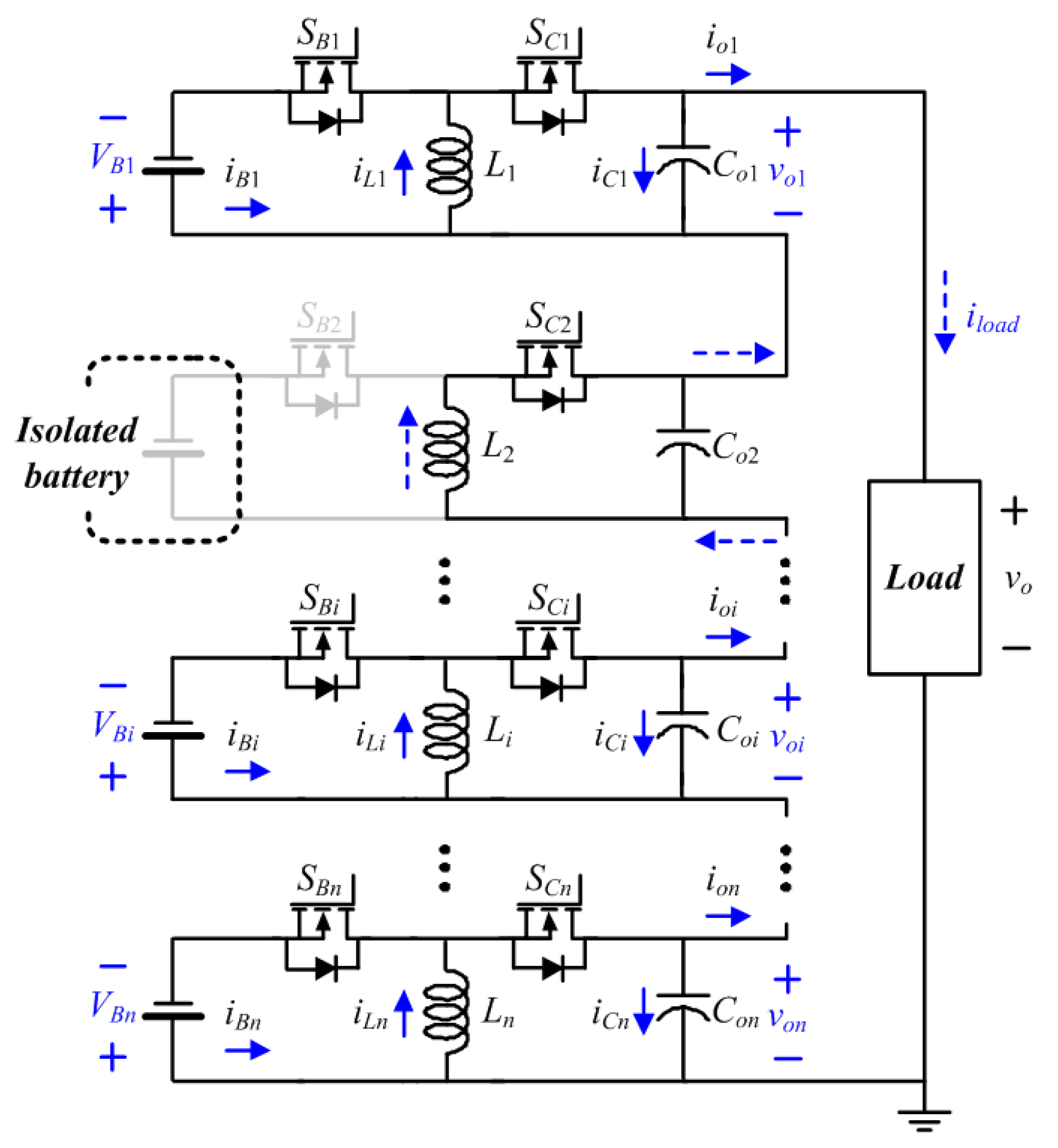
Figure 7.
The laboratory circuit of the battery power bank.
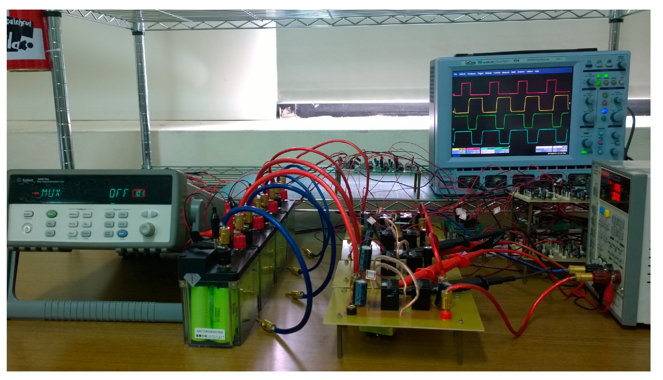
Figure 8.
Battery and inductor currents during the detection stage.
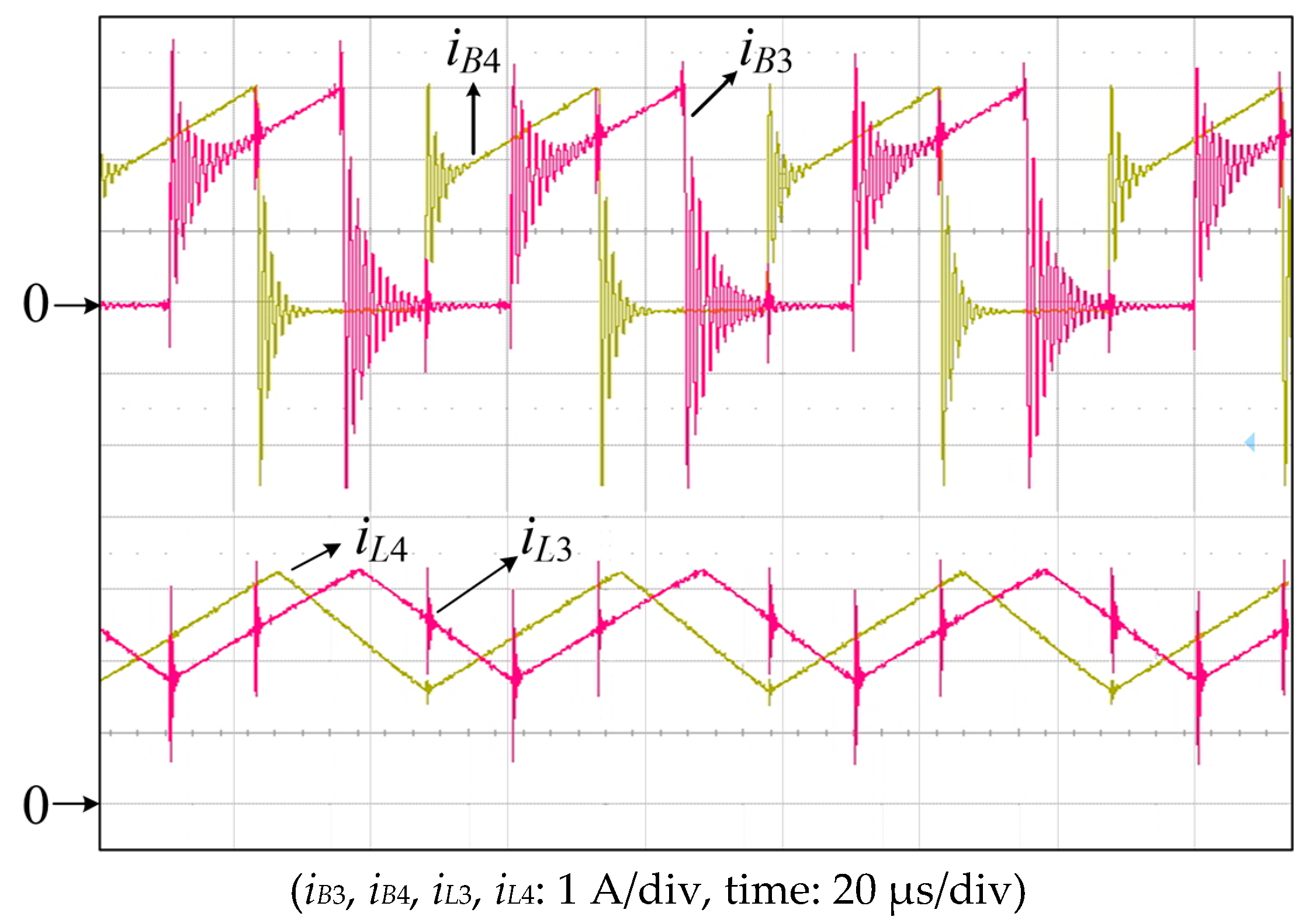
Figure 9.
Battery and inductor currents during the balancing stage.

Figure 10.
Battery voltages with balanced discharging.

Figure 11.
Output voltage of battery power bank.

Figure 12.
Switching spikes on the output voltage.

Figure 13.
Isolating transients on vL3, vo3, iL3, and io.

Figure 14.
The overall efficiencies of the battery power bank.


Table 1.
Circuit parameters.
| Load voltage, Vo | 48 V |
| Load current, Io | 2 A |
| Battery capacity | 4.6 Ah |
| Nominal voltage of battery pack, VN | 13.6 V |
| Knee point voltage, Vk | 12.4 V |
| Cut-off voltage, Vc | 10.0 V |
| Switching frequency, fs | 20 kHz |
| Inductance, Li | 200 μH |
| Output capacitance, Coi | 470 μF |
© 2017 by the authors. Licensee MDPI, Basel, Switzerland. This article is an open access article distributed under the terms and conditions of the Creative Commons Attribution (CC BY) license (http://creativecommons.org/licenses/by/4.0/).
Share and Cite
MDPI and ACS Style
Wu, T.-H.; Moo, C.-S.; Hou, C.-H. A Battery Power Bank with Series-Connected Buck–Boost-Type Battery Power Modules. Energies 2017, 10, 650. https://doi.org/10.3390/en10050650
AMA Style
Wu T-H, Moo C-S, Hou C-H. A Battery Power Bank with Series-Connected Buck–Boost-Type Battery Power Modules. Energies. 2017; 10(5):650. https://doi.org/10.3390/en10050650
Chicago/Turabian StyleWu, Tsung-Hsi, Chin-Sien Moo, and Chih-Hao Hou. 2017. "A Battery Power Bank with Series-Connected Buck–Boost-Type Battery Power Modules" Energies 10, no. 5: 650. https://doi.org/10.3390/en10050650
Note that from the first issue of 2016, this journal uses article numbers instead of page numbers. See further details here.