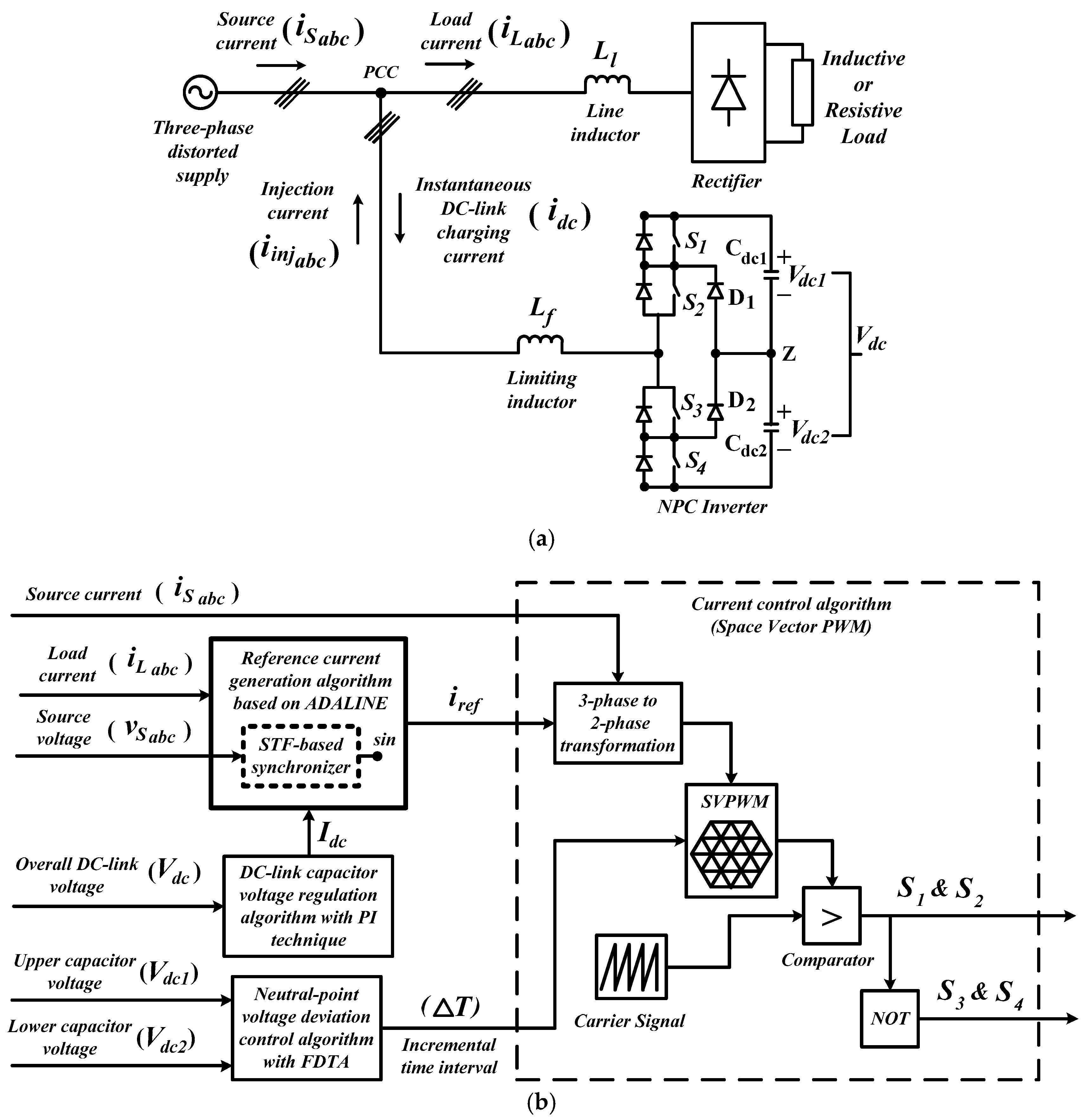
Figure 1.
Block diagram of (a) three-level NPC inverter-based SAPF and (b) the applied control algorithms.
Figure 1.
Block diagram of (a) three-level NPC inverter-based SAPF and (b) the applied control algorithms.
Figure 2.
Control structure of unified ADALINE algorithm [
30].
Figure 2.
Control structure of unified ADALINE algorithm [
30].
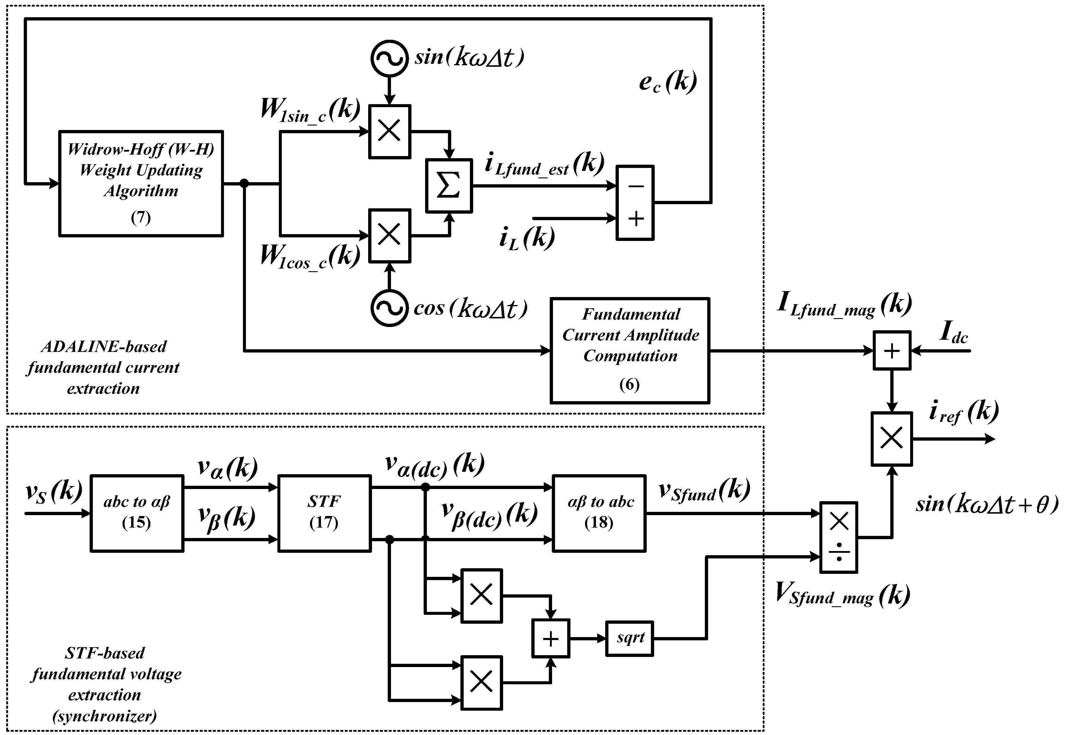
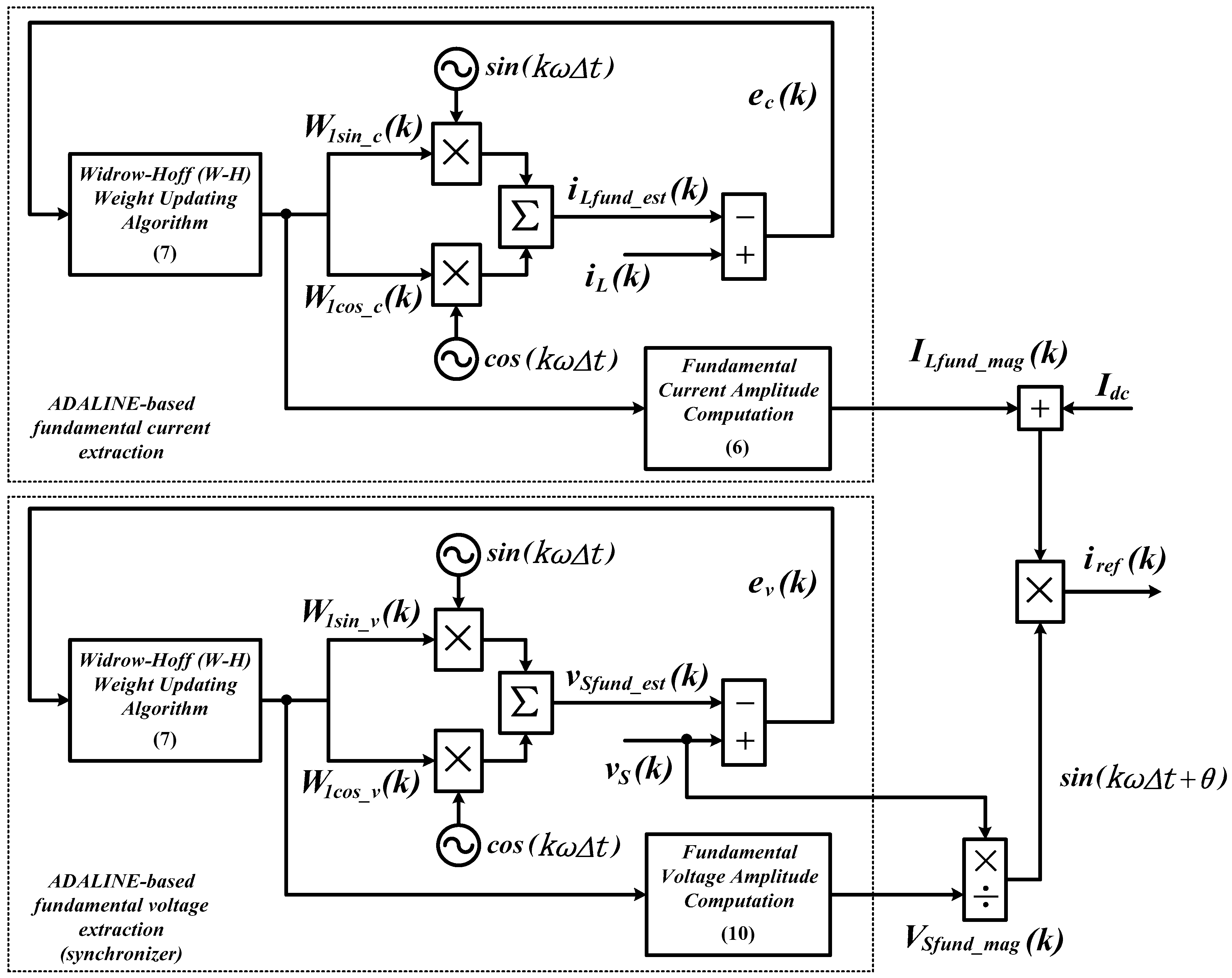
Figure 3.
Control structure of the proposed STF-based ADALINE algorithm.
Figure 3.
Control structure of the proposed STF-based ADALINE algorithm.
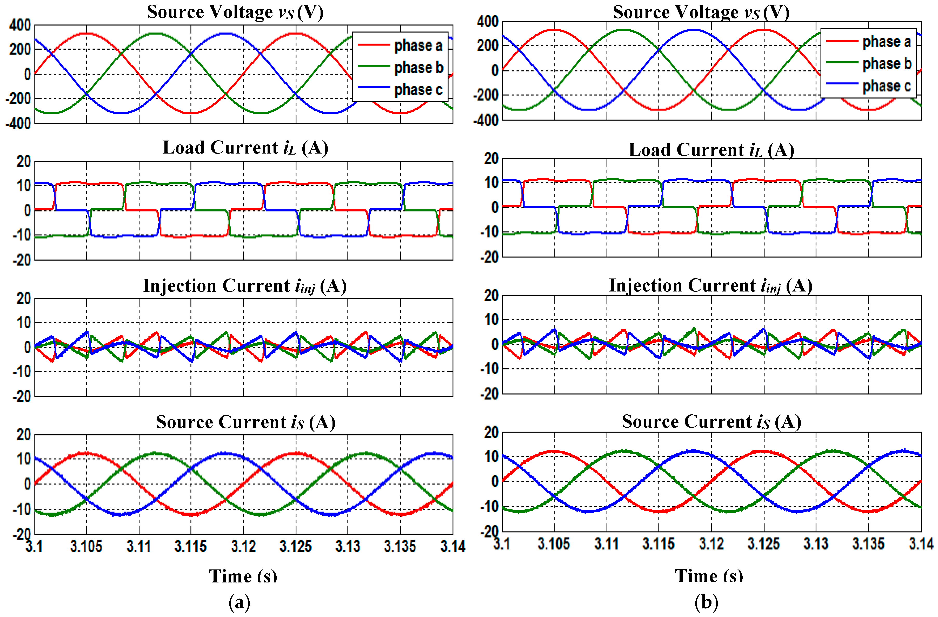
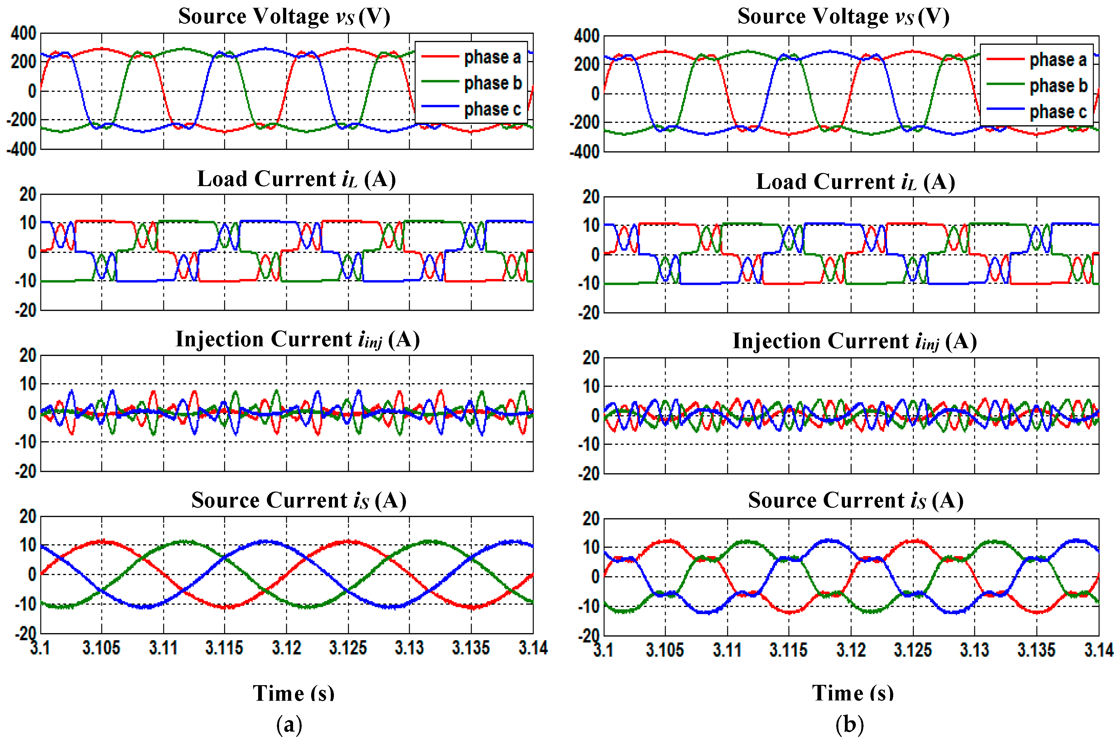
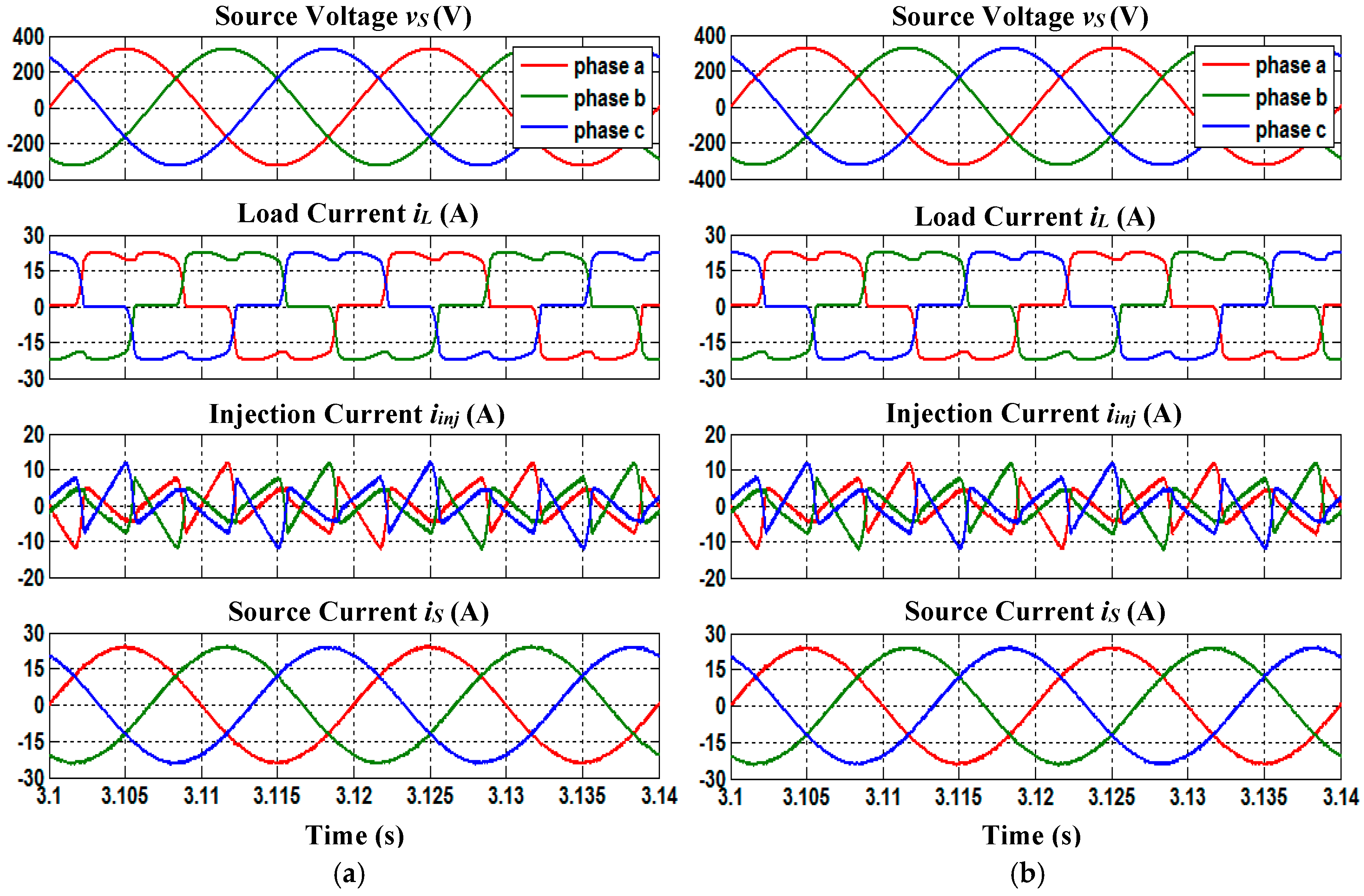
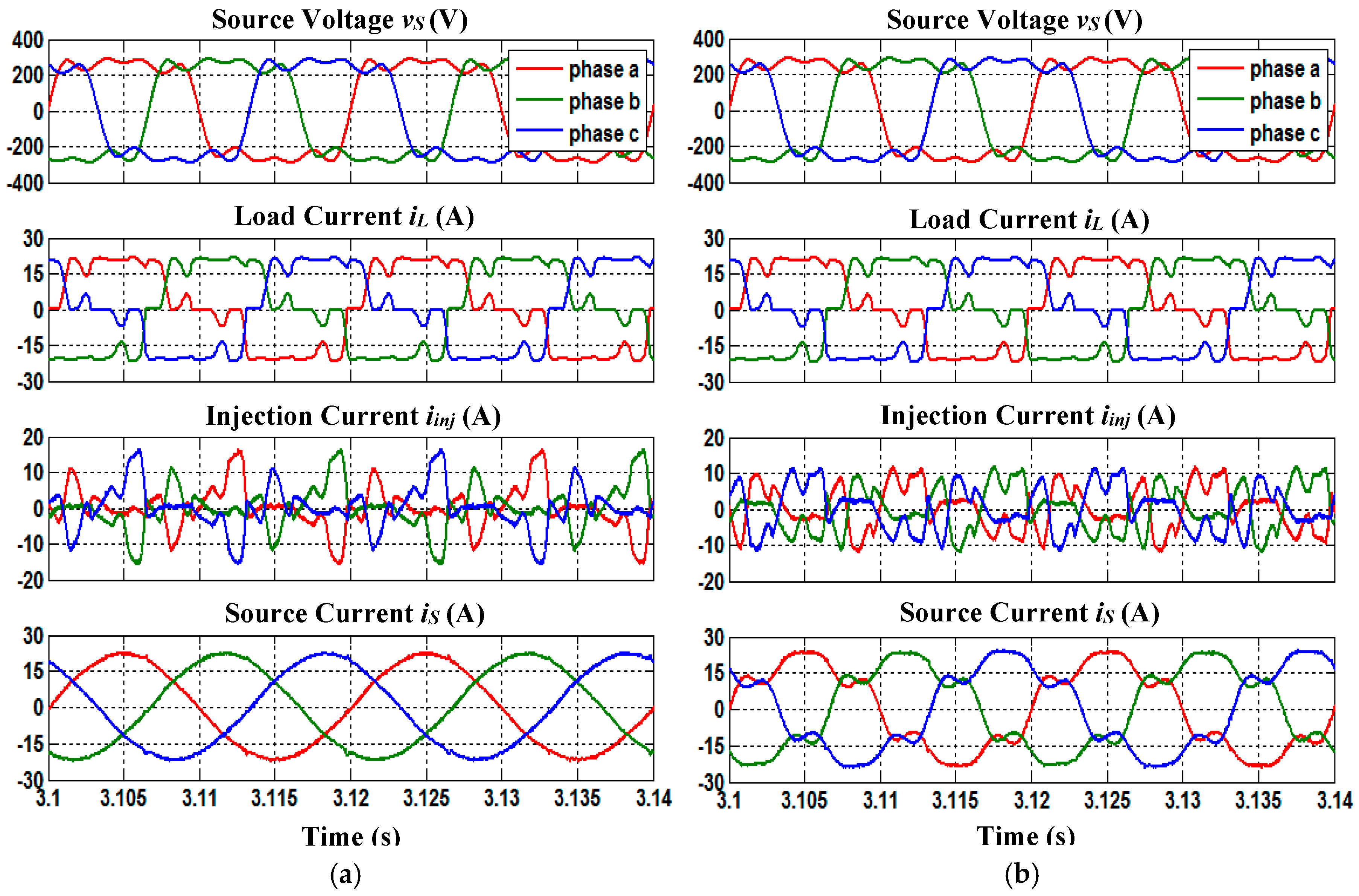
Figure 4.
Simulation waveforms of SAPF under case 1 condition which include three-phase source voltage , load current , injection current and source current , for inductive load, obtained by using (a) STF-based ADALINE and (b) unified ADALINE algorithms.
Figure 4.
Simulation waveforms of SAPF under case 1 condition which include three-phase source voltage , load current , injection current and source current , for inductive load, obtained by using (a) STF-based ADALINE and (b) unified ADALINE algorithms.
Figure 5.
Simulation waveforms of SAPF under case 1 condition which include three-phase source voltage , load current , injection current and source current , for resistive load, obtained by using (a) STF-based ADALINE and (b) unified ADALINE algorithms.
Figure 5.
Simulation waveforms of SAPF under case 1 condition which include three-phase source voltage , load current , injection current and source current , for resistive load, obtained by using (a) STF-based ADALINE and (b) unified ADALINE algorithms.
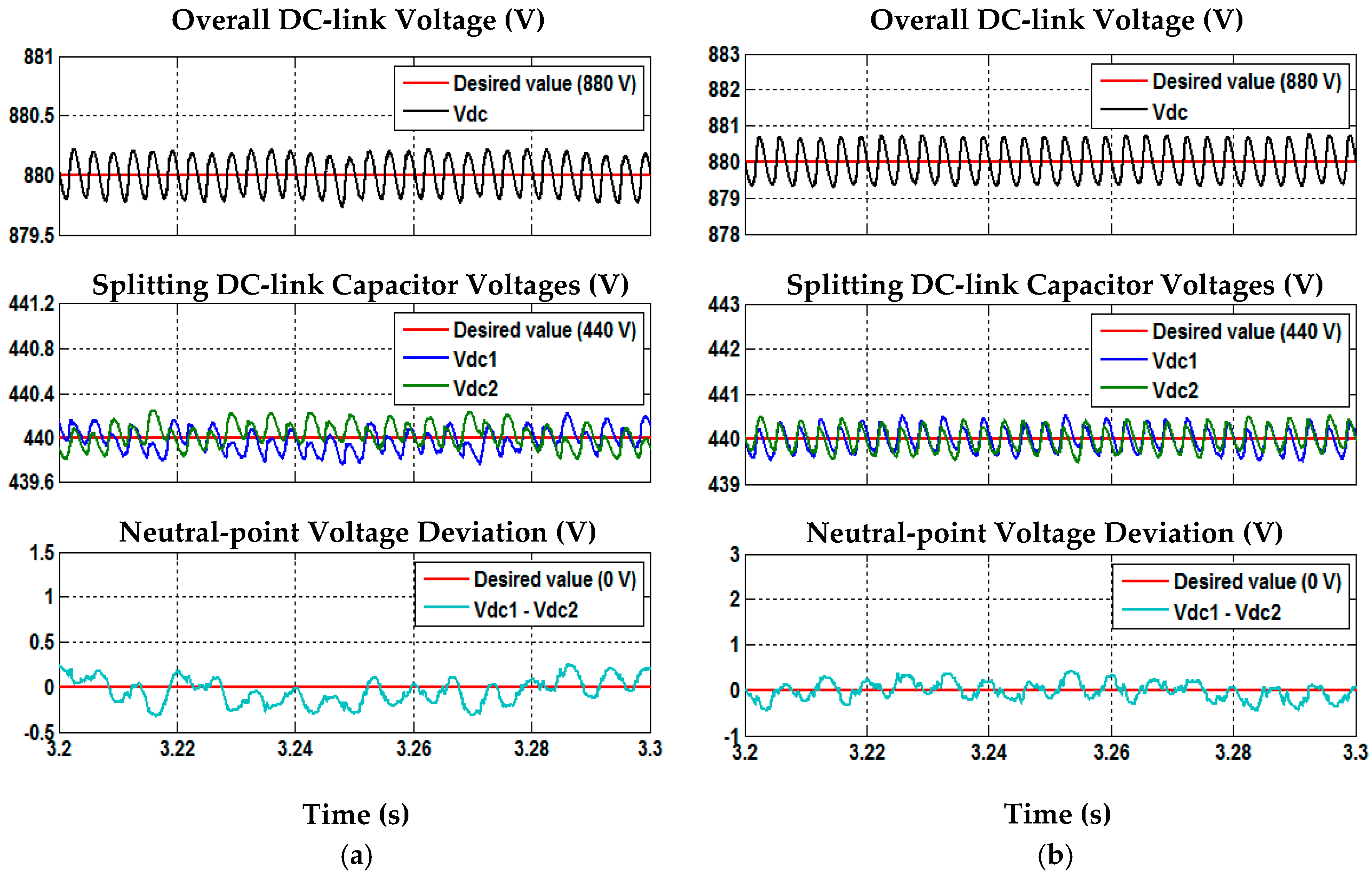
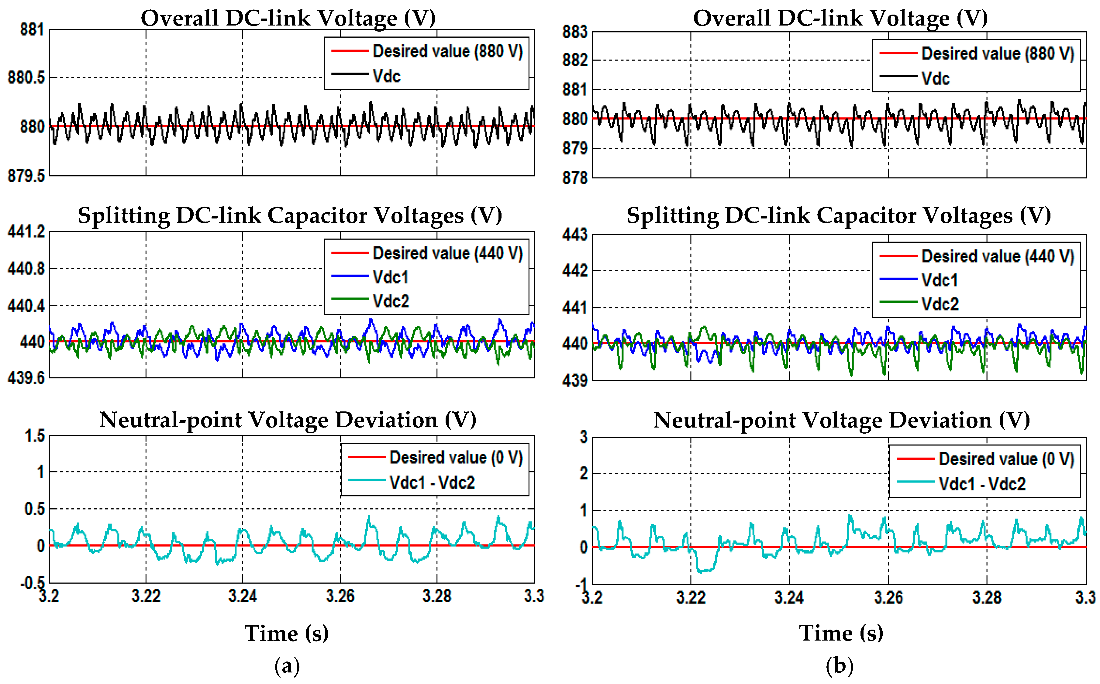
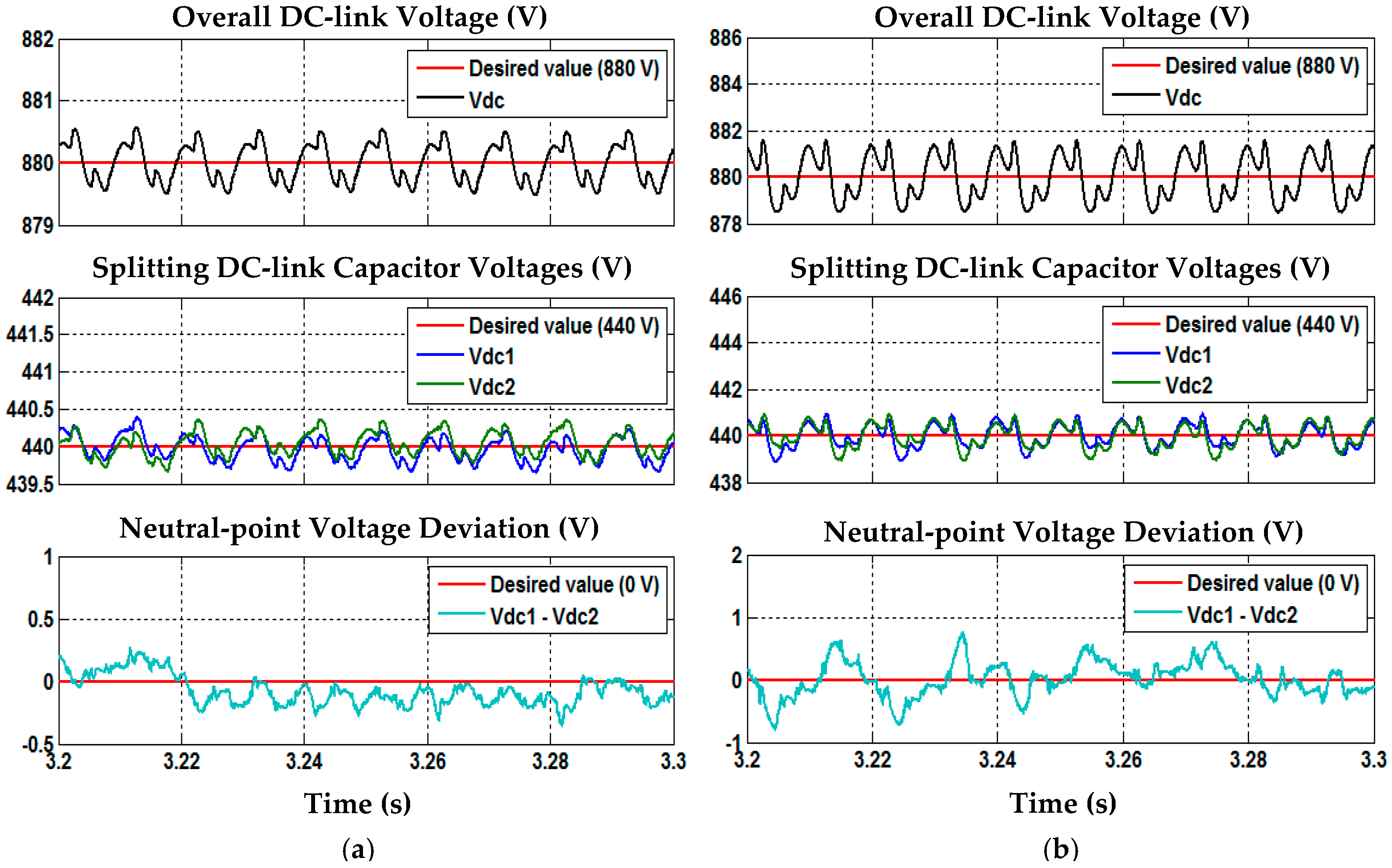
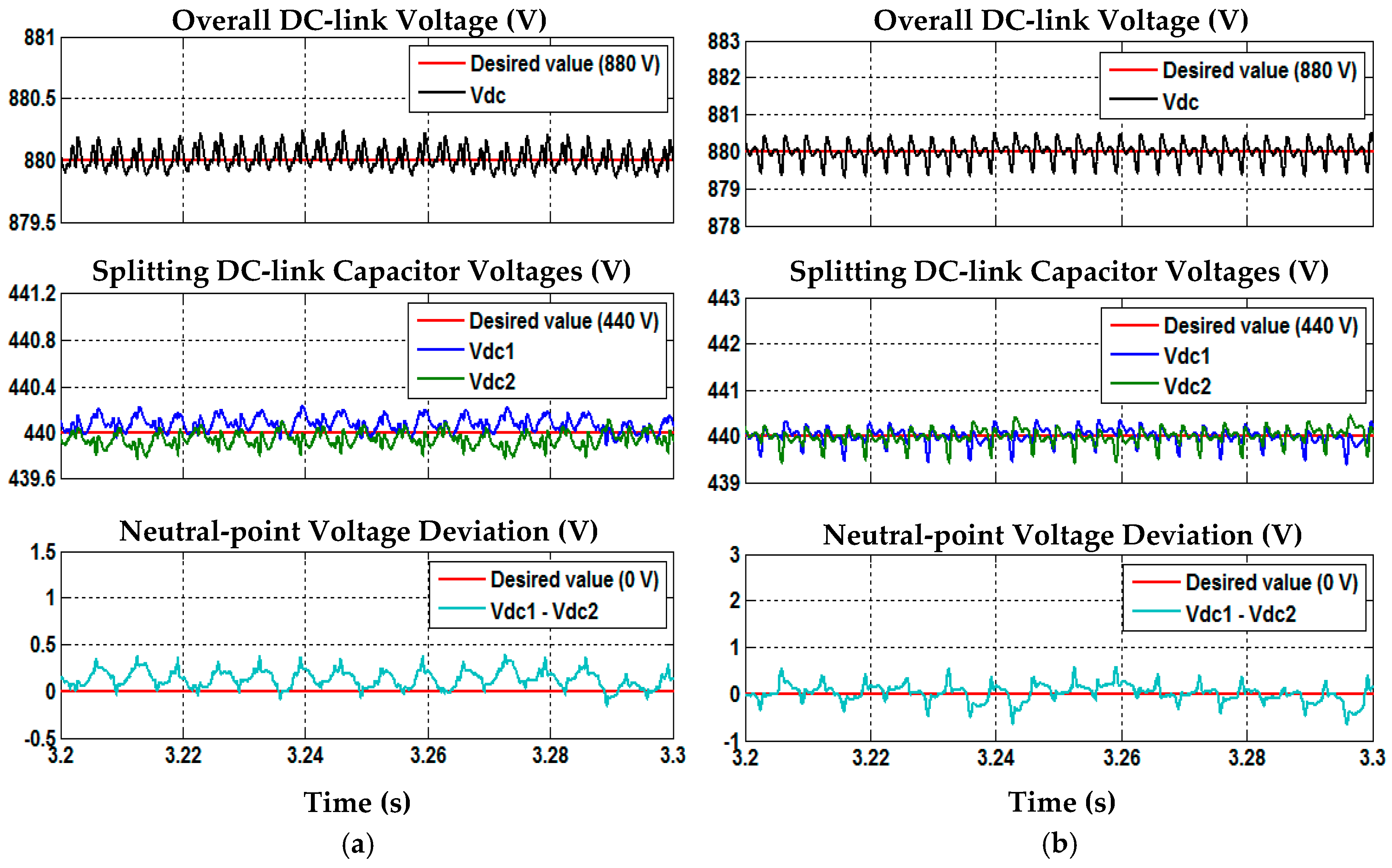
Figure 6.
Simulation waveforms of SAPF while using STF-based ADALINE algorithm under case 1 condition which include overall DC-link voltage , splitting DC-link capacitor voltages and , and neutral-point voltage deviation Vd (, for (a) inductive and (b) resistive loads.
Figure 6.
Simulation waveforms of SAPF while using STF-based ADALINE algorithm under case 1 condition which include overall DC-link voltage , splitting DC-link capacitor voltages and , and neutral-point voltage deviation Vd (, for (a) inductive and (b) resistive loads.
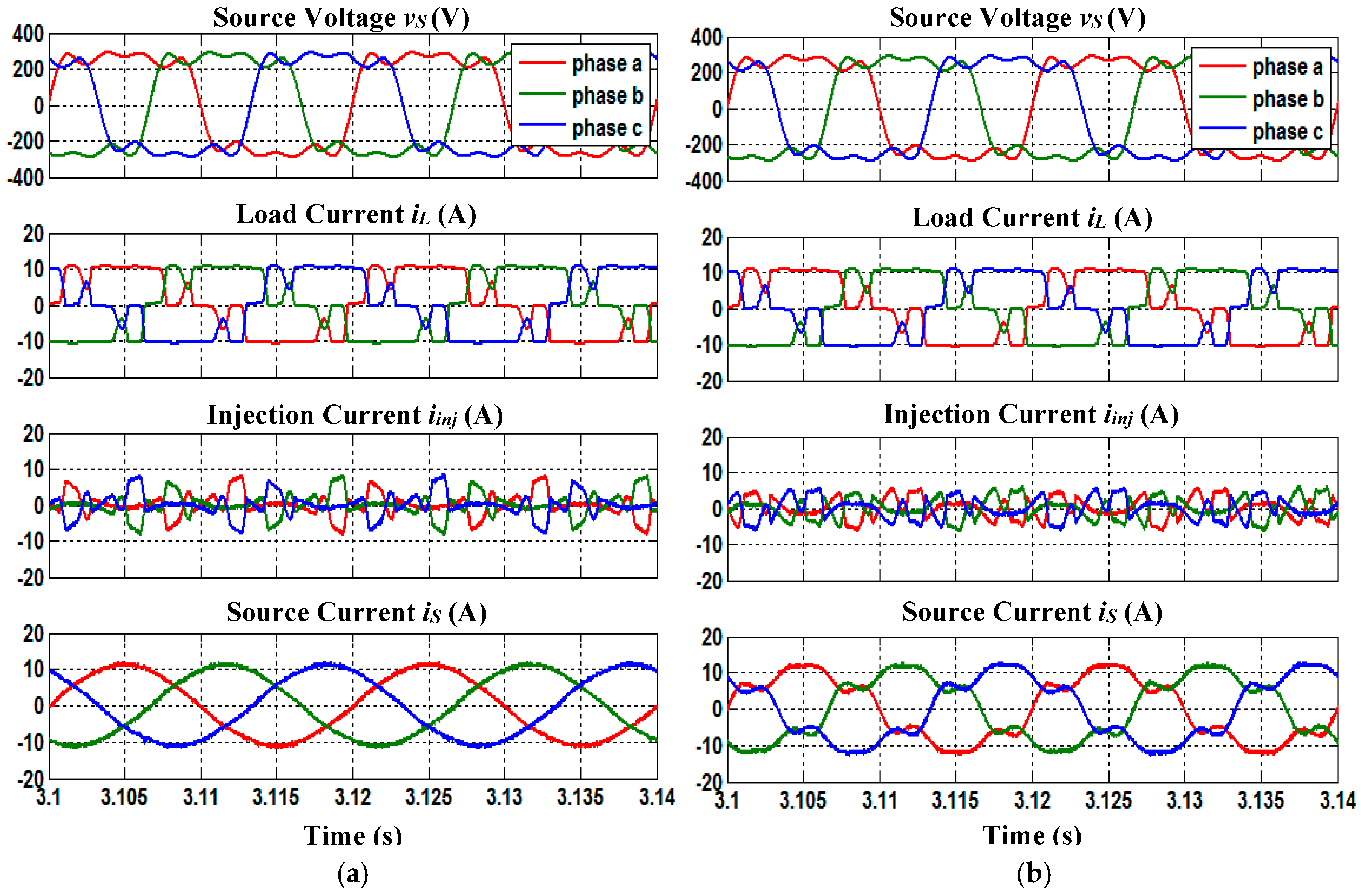
Figure 7.
Simulation waveforms of SAPF under case 2 condition which include three-phase source voltage , load current , injection current and source current , for inductive load, obtained by using (a) STF-based ADALINE and (b) unified ADALINE algorithms.
Figure 7.
Simulation waveforms of SAPF under case 2 condition which include three-phase source voltage , load current , injection current and source current , for inductive load, obtained by using (a) STF-based ADALINE and (b) unified ADALINE algorithms.
Figure 8.
Simulation waveforms of SAPF under case 2 condition which include three-phase source voltage , load current , injection current and source current , for resistive load, obtained by using (a) STF-based ADALINE and (b) unified ADALINE algorithms.
Figure 8.
Simulation waveforms of SAPF under case 2 condition which include three-phase source voltage , load current , injection current and source current , for resistive load, obtained by using (a) STF-based ADALINE and (b) unified ADALINE algorithms.
Figure 9.
Simulation waveforms of SAPF while using STF-based ADALINE algorithm under case 2 condition which include overall DC-link voltage , splitting DC-link capacitor voltages and , and neutral-point voltage deviation Vd (, for (a) inductive and (b) resistive loads.
Figure 9.
Simulation waveforms of SAPF while using STF-based ADALINE algorithm under case 2 condition which include overall DC-link voltage , splitting DC-link capacitor voltages and , and neutral-point voltage deviation Vd (, for (a) inductive and (b) resistive loads.
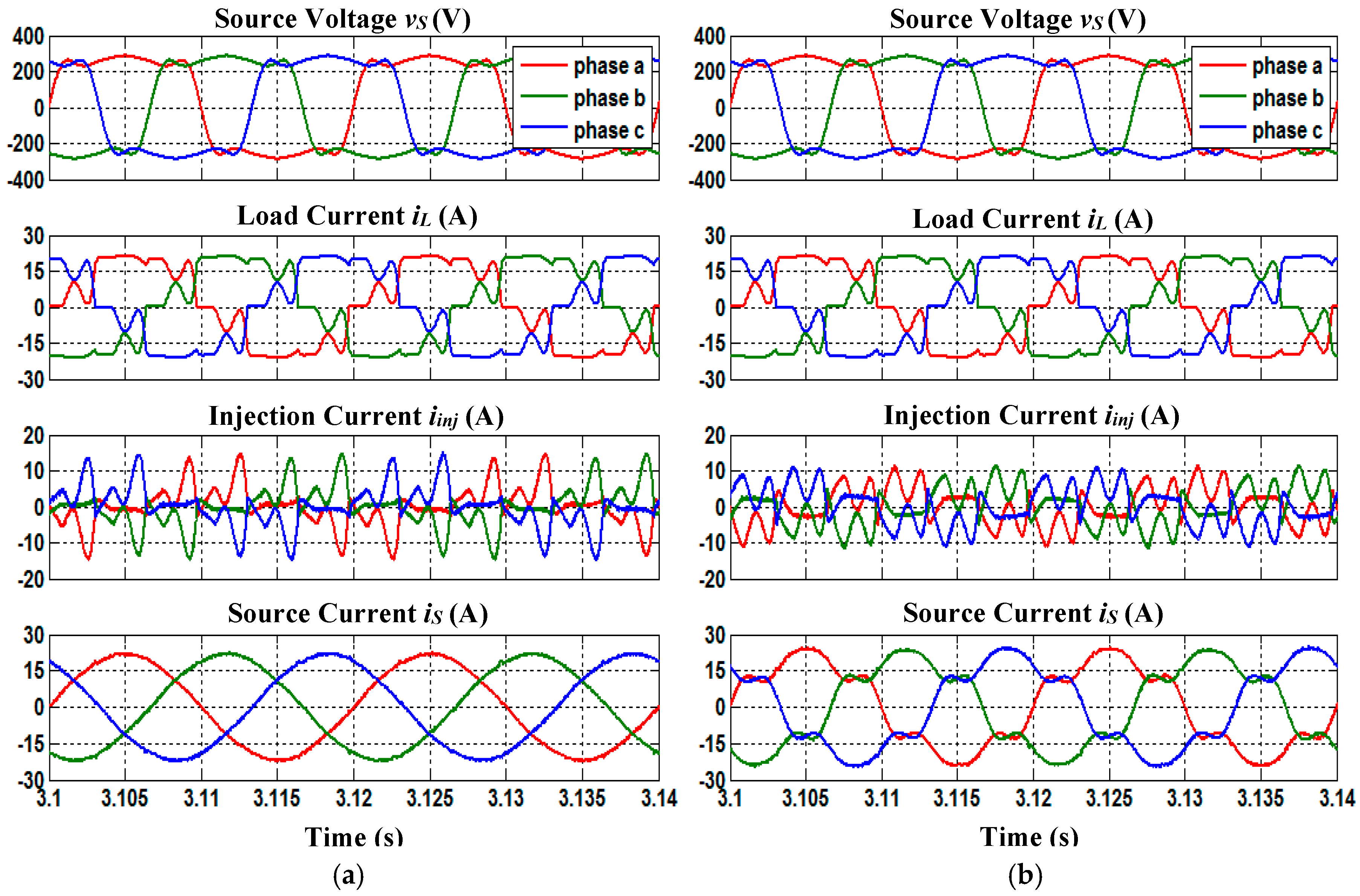
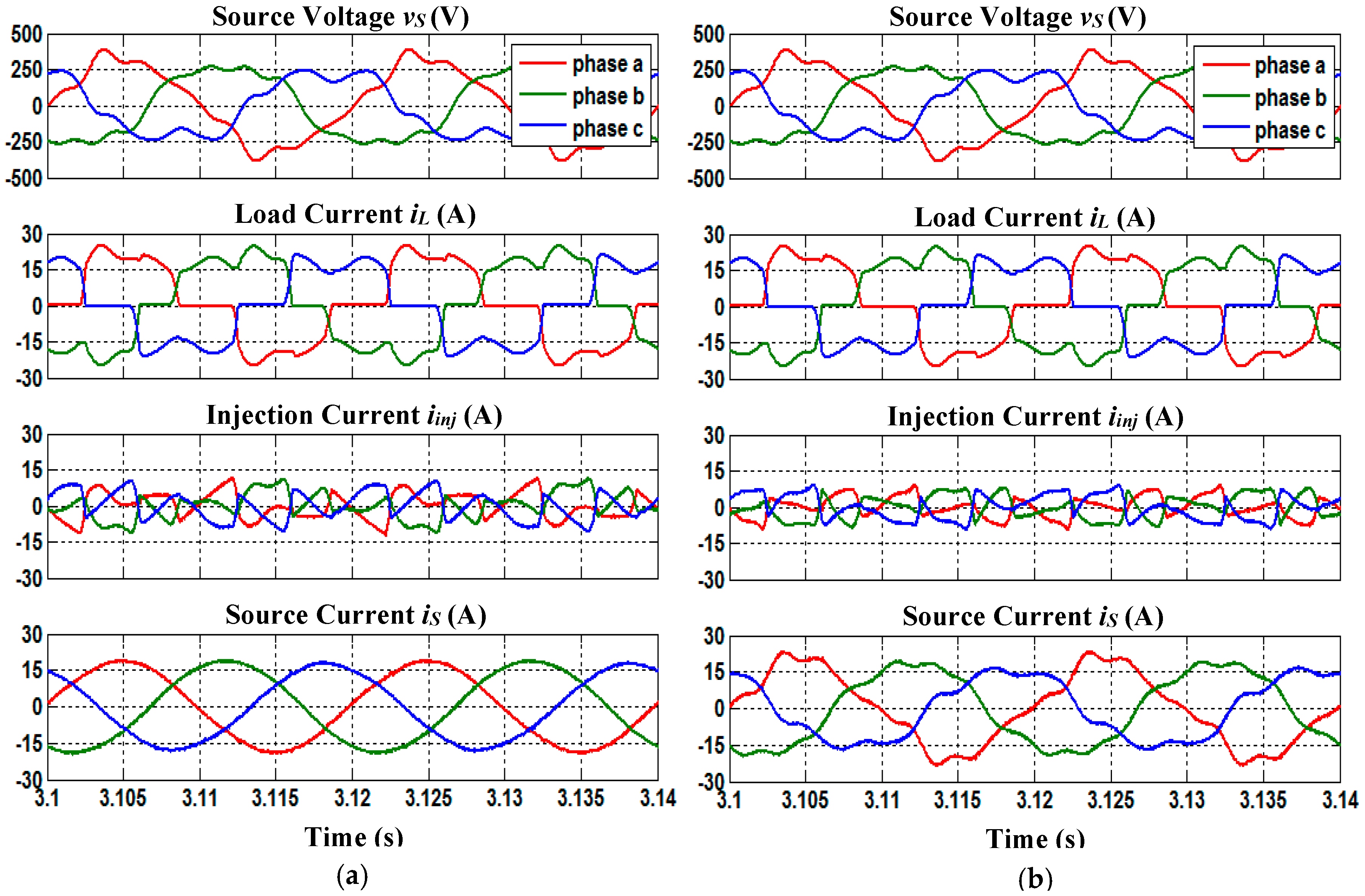
Figure 10.
Simulation waveforms of SAPF under case 3 condition which include three-phase source voltage , load current , injection current and source current , for inductive load, obtained by using (a) STF-based ADALINE and (b) unified ADALINE algorithms.
Figure 10.
Simulation waveforms of SAPF under case 3 condition which include three-phase source voltage , load current , injection current and source current , for inductive load, obtained by using (a) STF-based ADALINE and (b) unified ADALINE algorithms.
Figure 11.
Simulation waveforms of SAPF under case 3 condition which include three-phase source voltage , load current , injection current and source current , for resistive load, obtained by using (a) STF-based ADALINE and (b) unified ADALINE algorithms.
Figure 11.
Simulation waveforms of SAPF under case 3 condition which include three-phase source voltage , load current , injection current and source current , for resistive load, obtained by using (a) STF-based ADALINE and (b) unified ADALINE algorithms.
Figure 12.
Simulation waveforms of SAPF while using STF-based ADALINE algorithm under case 3 condition which include overall DC-link voltage , splitting DC-link capacitor voltages and , and neutral-point voltage deviation Vd (, for (a) inductive and (b) resistive loads.
Figure 12.
Simulation waveforms of SAPF while using STF-based ADALINE algorithm under case 3 condition which include overall DC-link voltage , splitting DC-link capacitor voltages and , and neutral-point voltage deviation Vd (, for (a) inductive and (b) resistive loads.
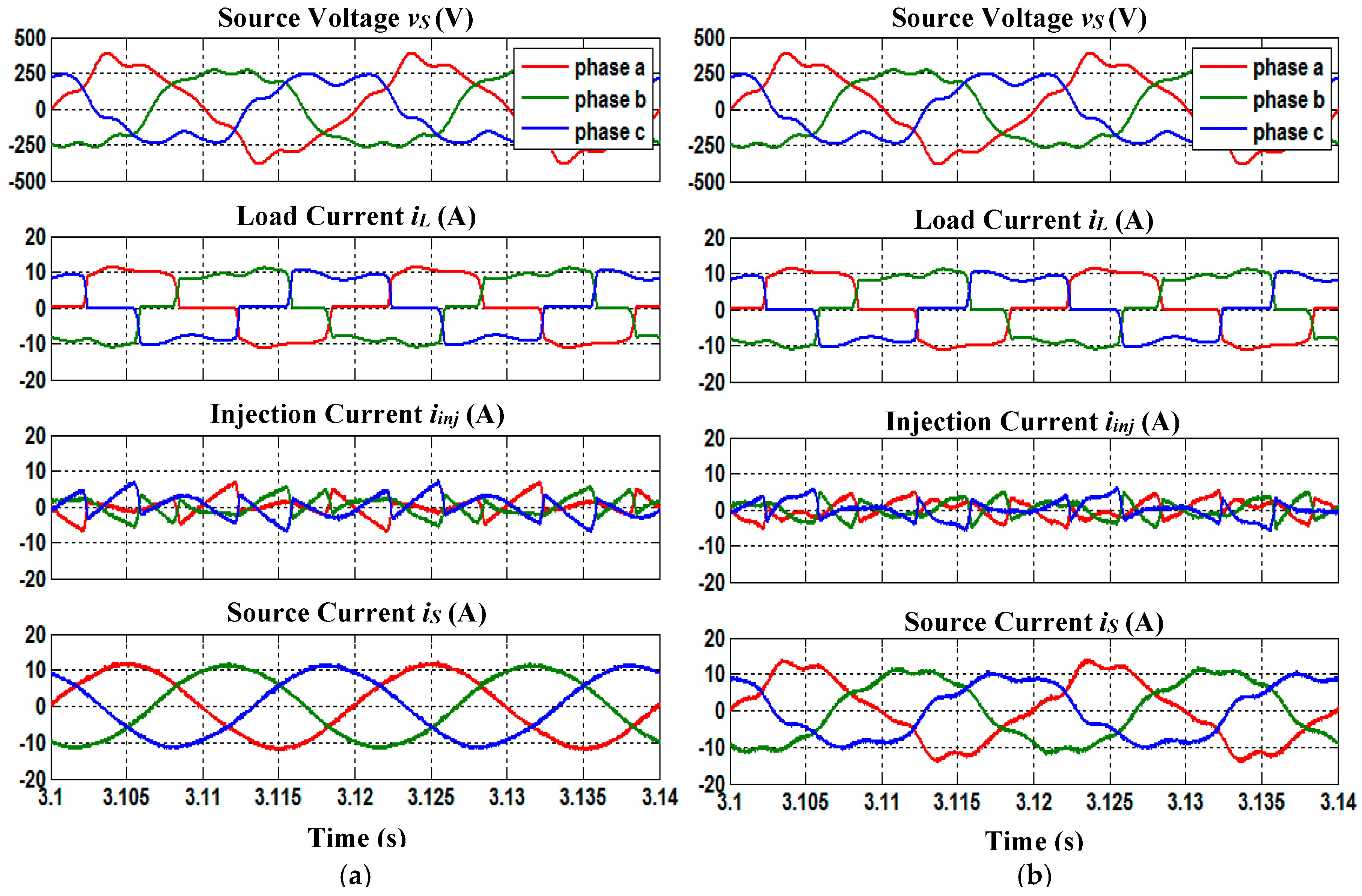
Figure 13.
Simulation waveforms of SAPF under case 4 condition which include three-phase source voltage , load current , injection current and source current , for inductive load, obtained by using (a) STF-based ADALINE and (b) unified ADALINE algorithms.
Figure 13.
Simulation waveforms of SAPF under case 4 condition which include three-phase source voltage , load current , injection current and source current , for inductive load, obtained by using (a) STF-based ADALINE and (b) unified ADALINE algorithms.
Figure 14.
Simulation waveforms of SAPF under case 4 condition which include three-phase source voltage , load current , injection current and source current , for resistive load, obtained by using (a) STF-based ADALINE and (b) unified ADALINE algorithms.
Figure 14.
Simulation waveforms of SAPF under case 4 condition which include three-phase source voltage , load current , injection current and source current , for resistive load, obtained by using (a) STF-based ADALINE and (b) unified ADALINE algorithms.
Figure 15.
Simulation waveforms of SAPF while using STF-based ADALINE algorithm under case 4 condition which include overall DC-link voltage , splitting DC-link capacitor voltages and , and neutral-point voltage deviation Vd (, for (a) inductive and (b) resistive loads.
Figure 15.
Simulation waveforms of SAPF while using STF-based ADALINE algorithm under case 4 condition which include overall DC-link voltage , splitting DC-link capacitor voltages and , and neutral-point voltage deviation Vd (, for (a) inductive and (b) resistive loads.
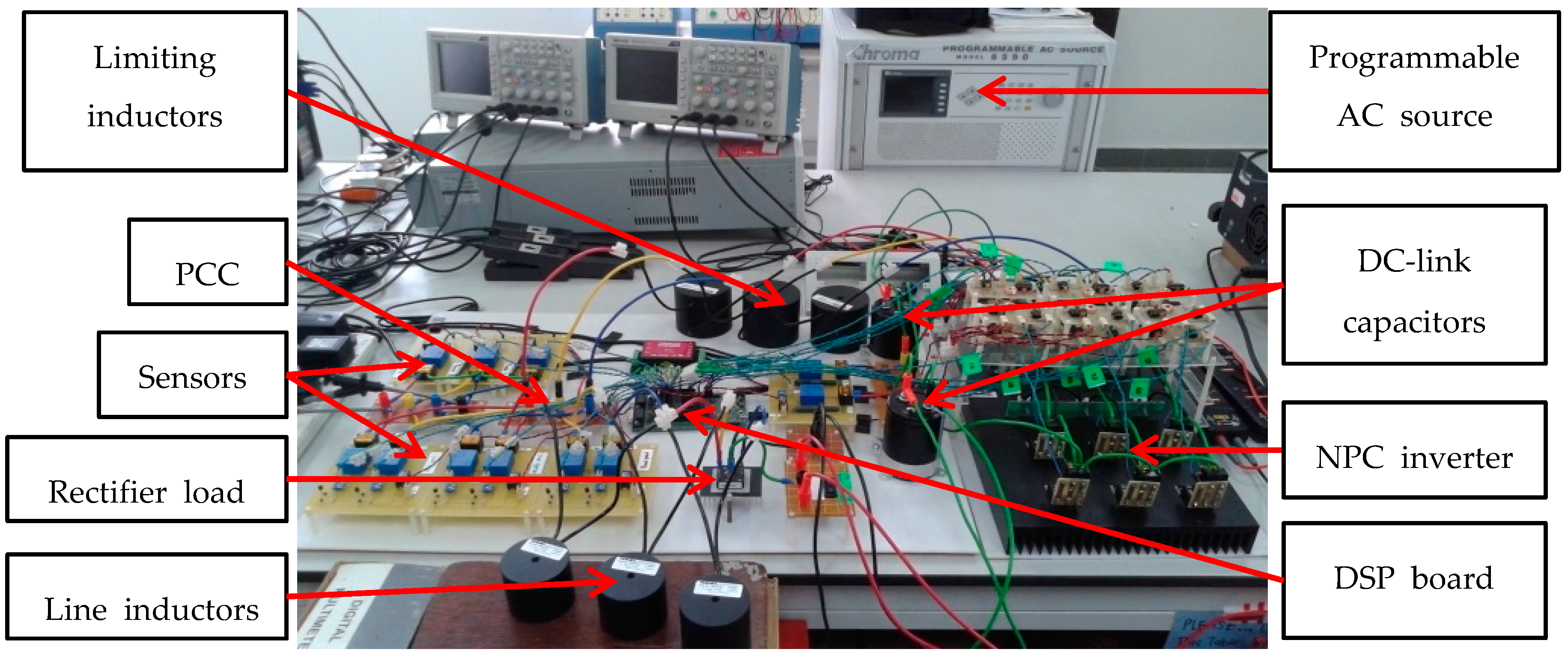
Figure 16.
The hardware setup.
Figure 16.
The hardware setup.
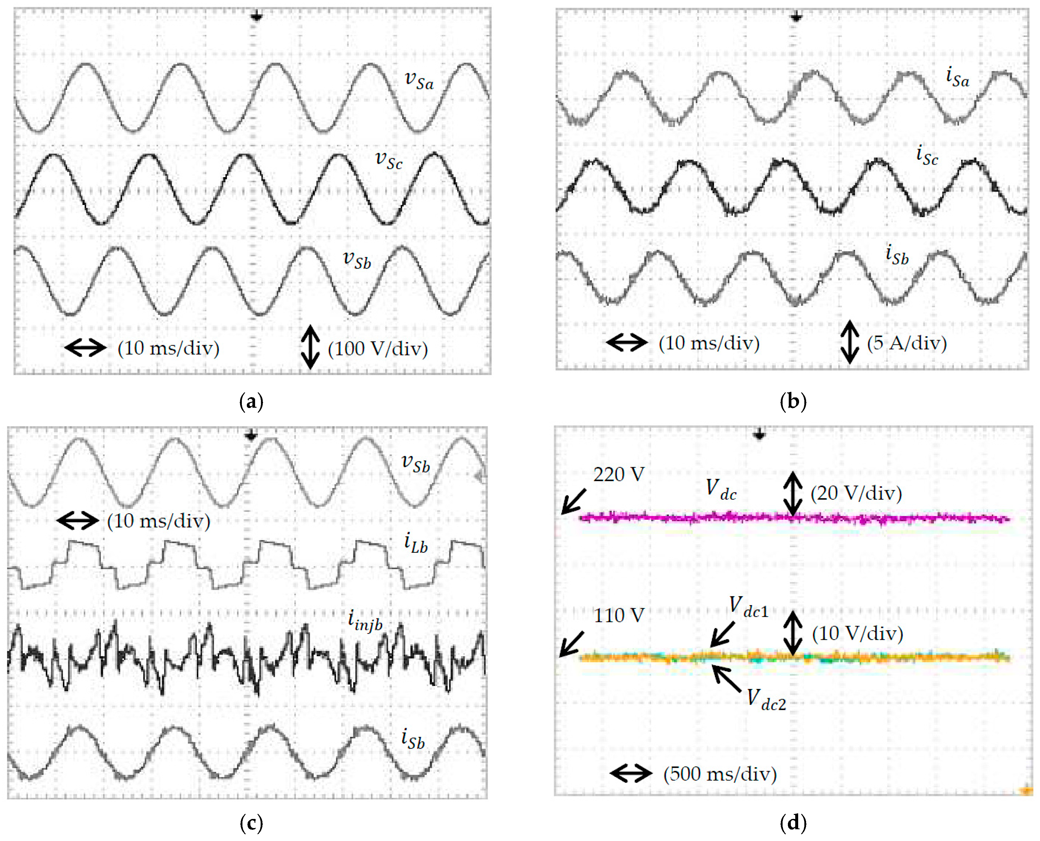
Figure 17.
Experimental waveforms of SAPF while using STF-based ADALINE algorithm, obtained for inductive load under case A condition which include (a) three-phase source voltage ; (b) three-phase source current ; (c) phase b source voltage (100 V/div), load current (5 A/div), injection current (2 A/div), and source current (5 A/div); and (d) DC-link voltages.
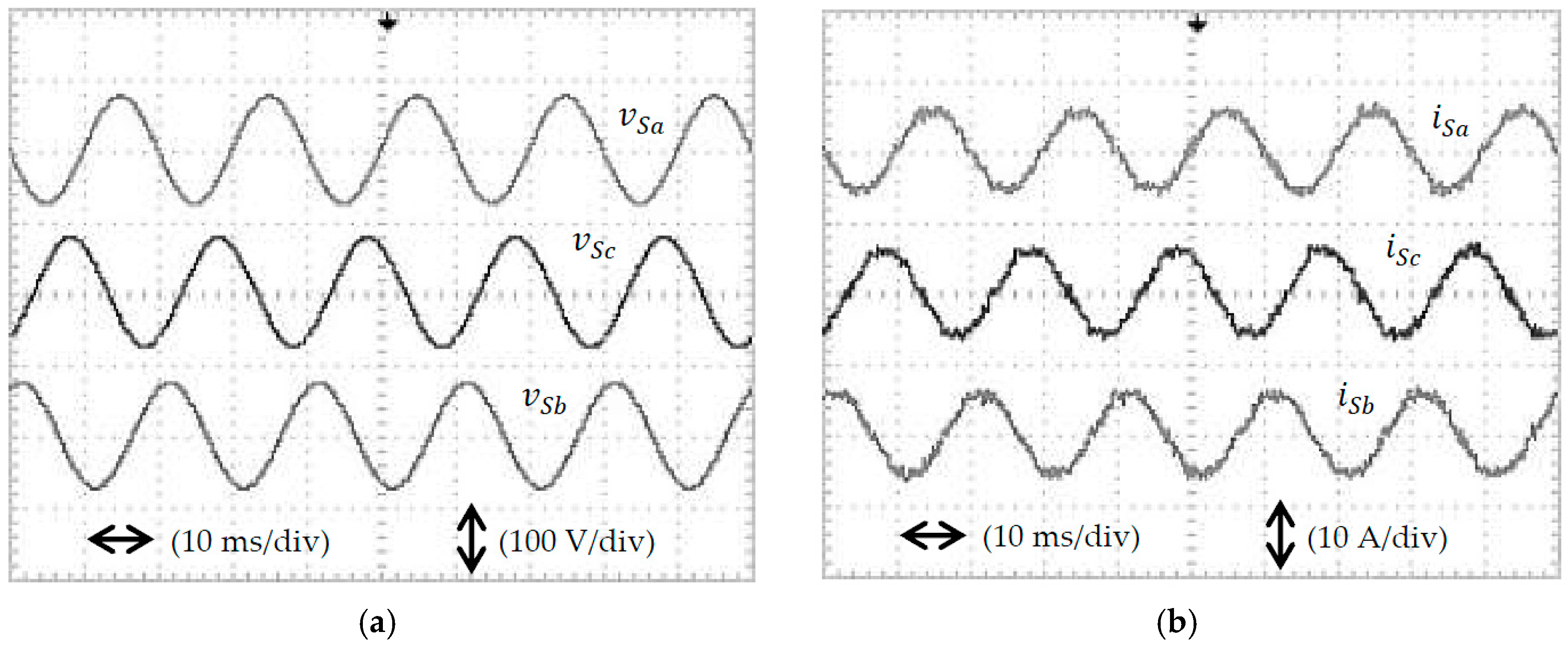
Figure 18.
Experimental waveforms of SAPF while using STF-based ADALINE algorithm, obtained for resistive load under case A condition which include (a) three-phase source voltage ; (b) three-phase source current ; (c) phase b source voltage (100 V/div), load current (10 A/div), injection current (5 A/div), and source current (10 A/div); and (d) DC-link voltages.
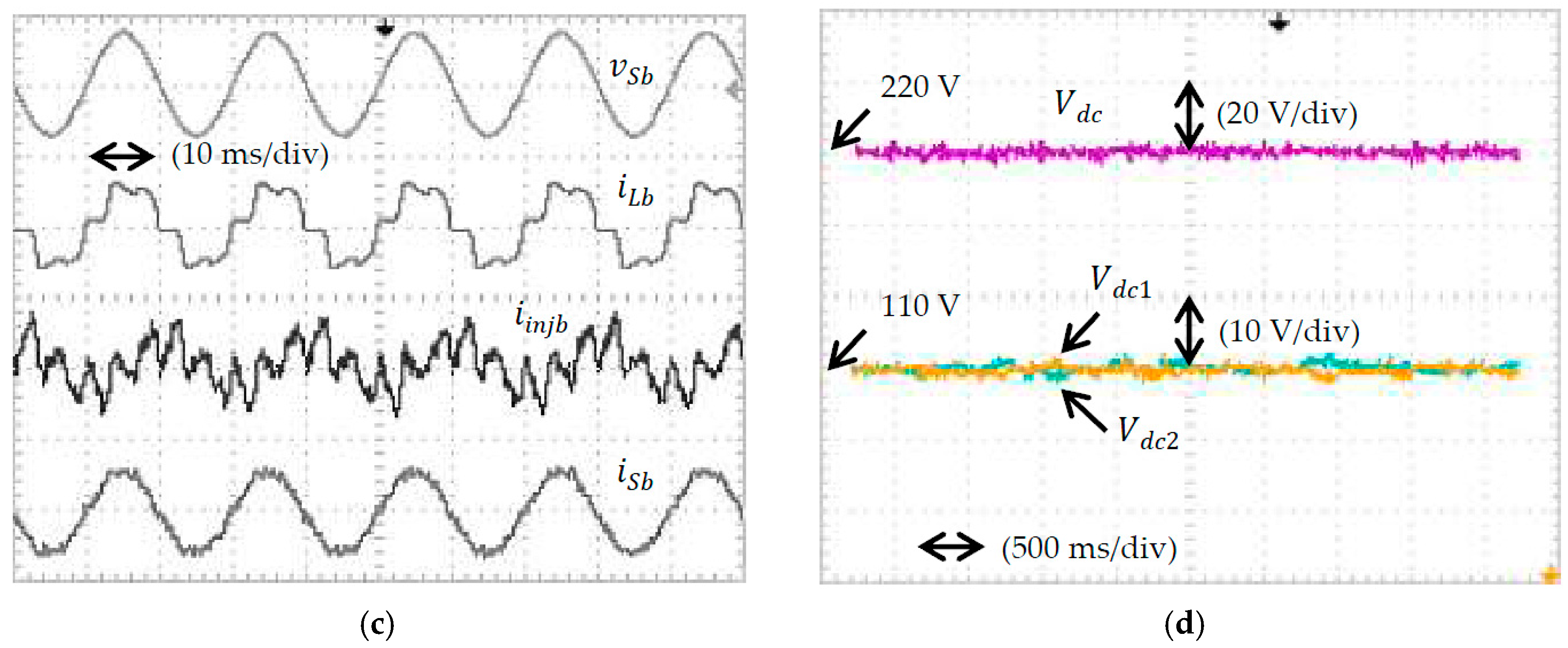
Figure 19.
Experimental waveforms of SAPF while using STF-based ADALINE algorithm, obtained for inductive load under case B condition which include (a) three-phase source voltage ; (b) three-phase source current ; (c) phase b source voltage (100 V/div), load current (5 A/div), injection current (2 A/div), and source current (5 A/div); and (d) DC-link voltages.
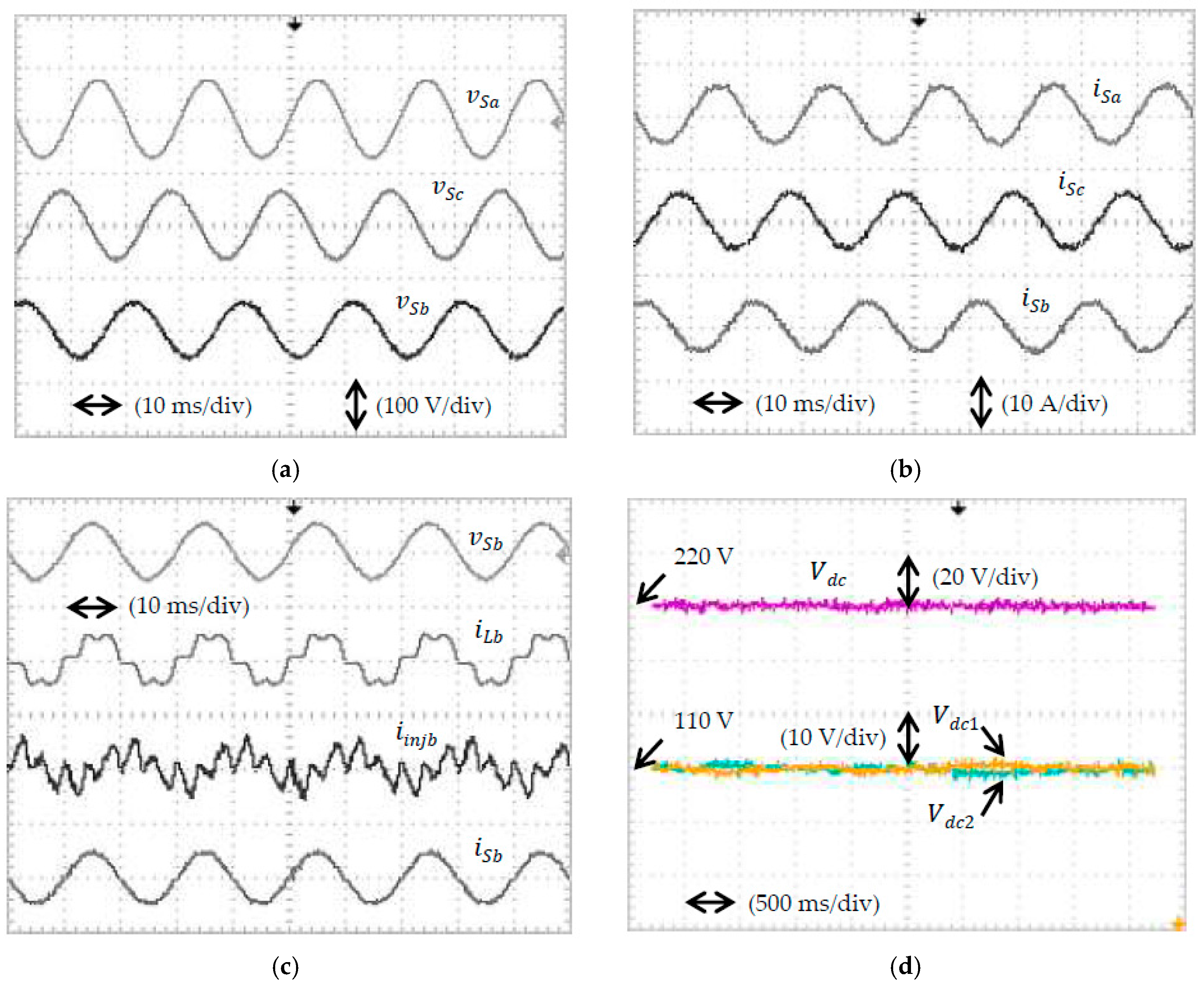
Figure 20.
Experimental waveforms of SAPF while using STF-based ADALINE algorithm, obtained for resistive load under case B condition which include (a) three-phase source voltage ; (b) three-phase source current ; (c) phase b source voltage (100 V/div), load current (10 A/div), injection current (5 A/div), and source current (10 A/div); and (d) DC-link voltages.
Table 1.
Parameter specifications for the proposed SAPF.
Table 1.
Parameter specifications for the proposed SAPF.
| Parameter | Value | Unit |
|---|
| Fundamental source voltage (line to line) | 400 (rms) | V |
| Fundamental frequency | 50 | Hz |
| DC-link capacitor | 3300 (each) | μF |
| Overall DC-link reference voltage | 880 | V |
| Limiting inductor | 5 | mH |
| Switching frequency | 25 | kHz |
Table 2.
THD values of source current before and after connecting SAPF, obtained under case 1 condition (Simulation Result).
Table 2.
THD values of source current before and after connecting SAPF, obtained under case 1 condition (Simulation Result).
| Reference Current Generation Algorithm | Total Harmonic Distortion, THD (%) |
|---|
| Phase a | Phase b | Phase c |
|---|
| Inductive | Resistive | Inductive | Resistive | Inductive | Resistive |
|---|
| | Before Connecting SAPF |
| N/A | 27.34 | 27.01 | 27.34 | 27.01 | 27.34 | 27.01 |
| | After Connecting SAPF |
| STF-based ADALINE | 2.60 | 1.29 | 2.57 | 1.28 | 2.57 | 1.31 |
| Unified ADALINE | 3.28 | 1.38 | 3.34 | 1.39 | 3.26 | 1.42 |
Table 3.
THD values of source current before and after connecting SAPF, obtained under case 2 condition (Simulation Result).
Table 3.
THD values of source current before and after connecting SAPF, obtained under case 2 condition (Simulation Result).
| Reference Current Generation Algorithm | Total Harmonic Distortion, THD (%) |
|---|
| Phase a | Phase b | Phase c |
|---|
| Inductive | Resistive | Inductive | Resistive | Inductive | Resistive |
|---|
| | Before Connecting SAPF |
| N/A | 33.54 | 25.56 | 33.54 | 25.56 | 33.54 | 25.56 |
| | After Connecting SAPF |
| STF-based ADALINE | 3.19 | 2.00 | 3.19 | 1.96 | 3.21 | 1.97 |
| Unified ADALINE | 21.12 | 20.71 | 21.73 | 21.18 | 20.89 | 20.48 |
Table 4.
THD values of source current before and after connecting SAPF, obtained under case 3 condition (Simulation Result).
Table 4.
THD values of source current before and after connecting SAPF, obtained under case 3 condition (Simulation Result).
| Reference Current Generation Algorithm | Total Harmonic Distortion, THD (%) |
|---|
| Phase a | Phase b | Phase c |
|---|
| Inductive | Resistive | Inductive | Resistive | Inductive | Resistive |
|---|
| | Before Connecting SAPF |
| N/A | 39.86 | 37.70 | 39.86 | 37.70 | 39.86 | 37.70 |
| | After Connecting SAPF |
| STF-based ADALINE | 3.95 | 3.10 | 3.89 | 3.13 | 3.94 | 3.06 |
| Unified ADALINE | 22.59 | 22.36 | 23.01 | 22.86 | 22.27 | 22.05 |
Table 5.
THD values of source current before and after connecting SAPF, obtained under case 4 condition (Simulation Result).
Table 5.
THD values of source current before and after connecting SAPF, obtained under case 4 condition (Simulation Result).
| Reference Current Generation Algorithm | Total Harmonic Distortion, THD (%) |
|---|
| Phase a | Phase b | Phase c |
|---|
| Inductive | Resistive | Inductive | Resistive | Inductive | Resistive |
|---|
| | Before Connecting SAPF |
| N/A | 31.95 | 34.04 | 26.57 | 23.98 | 34.16 | 35.53 |
| | After Connecting SAPF |
| STF-based ADALINE | 3.31 | 2.86 | 2.60 | 1.87 | 2.74 | 2.27 |
| Unified ADALINE | 17.82 | 17.49 | 11.49 | 11.31 | 16.99 | 16.55 |
Table 6.
THD values of source current before and after mitigation by SAPF with STF-based ADALINE algorithm, obtained under cases A and B conditions (Experimental Result).
Table 6.
THD values of source current before and after mitigation by SAPF with STF-based ADALINE algorithm, obtained under cases A and B conditions (Experimental Result).
| Cases of Source Voltage Conditions | Total Harmonic Distortion, THD (%) |
|---|
| Phase a | Phase b | Phase c |
|---|
| Inductive | Resistive | Inductive | Resistive | Inductive | Resistive |
|---|
| | Before Connecting SAPF |
| Case A | 26.10 | 24.83 | 25.88 | 24.85 | 26.27 | 25.06 |
| Case B | 22.73 | 21.65 | 27.32 | 26.33 | 23.40 | 22.18 |
| | After Connecting SAPF |
| Case A | 3.48 | 3.21 | 3.65 | 3.31 | 3.54 | 3.25 |
| Case B | 3.52 | 3.35 | 4.15 | 3.91 | 3.84 | 3.66 |


