Article

Performance Analysis of a Four-Switch Three-Phase Grid-Side Converter with Modulation Simplification in a Doubly-Fed Induction Generator-Based Wind Turbine (DFIG-WT) with Different External Disturbances

1
The State Key Laboratory of Mechanical Transmissions, Chongqing University, Chongqing 400044, China
2
Department of Electrical Engineering and Electronics, University of Liverpool, Liverpool L69 3GJ, UK
3
School of Electric Power Engineering, South China University of Technology, Guangzhou 510640, China
4
Department of Electrical Engineering and Computer Science, University of Tennessee, Knoxville, TN 37996, USA
*
Author to whom correspondence should be addressed.
Energies 2017, 10(5), 706; https://doi.org/10.3390/en10050706
Submission received: 9 March 2017 / Revised: 12 May 2017 / Accepted: 14 May 2017 / Published: 18 May 2017
(This article belongs to the Section F: Electrical Engineering)

Abstract

:
This paper investigates the performance of a fault-tolerant four-switch three-phase (FSTP) grid-side converter (GSC) in a doubly-fed induction generator-based wind turbine (DFIG-WT). The space vector pulse width modulation (SVPWM) technique is simplified and unified duty ratios are used for controlling the FSTP GSC. Steady DC-bus voltage, sinusoidal three-phase grid currents and unity power factor are obtained. In addition, the balance of capacitor voltages is accomplished based on the analysis of current flows at the midpoint of DC bus in different operational modes. Besides, external disturbances such as fluctuating wind speed and grid voltage sag are considered to test its fault-tolerant ability. Furthermore, the effects of fluctuating wind speed on the performance of DFIG-WT system are explained according to an approximate expression of the turbine torque. The performance of the proposed FSTP GSC is simulated in Matlab/Simulink 2016a based on a detailed 1.5 MW DFIG-WT Simulink model. Experiments are carried out on a 2 kW platform by using a discrete signal processor (DSP) TMS320F28335 controller to validate the reliability of DFIG-WT for the cases with step change of the stator active power and grid voltage sag, respectively.

1. Introduction

To achieve the purpose of sustainable development, attention is being paid to clean energy resources [1,2]. Among all the renewable resources, wind energy has relatively high competitiveness [3,4]. It is estimated that the proportion of wind energy in the total power generation all over the world by 2050 will be 15–18% [5]. In large-scale wind turbine penetrated power systems, doubly-fed induction generators (DFIGs) are usually applied because of their variable speed constant frequency (VSCF) operating ability [
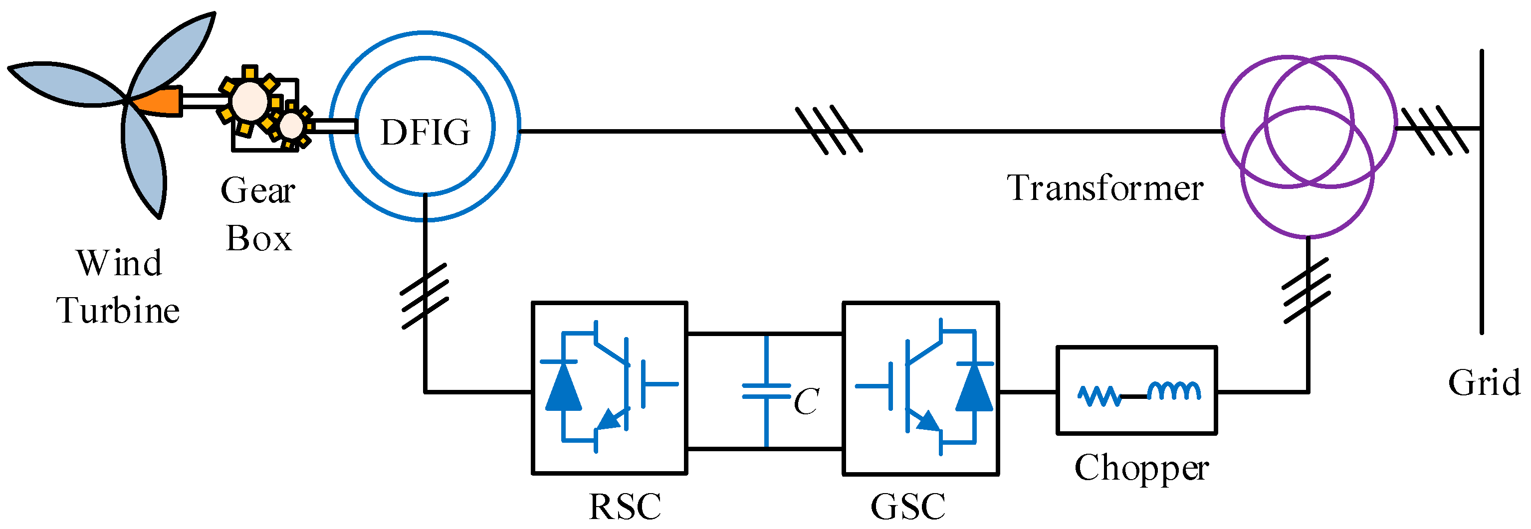
6]. The commonly used configuration of a DFIG-based power generation system is shown in 
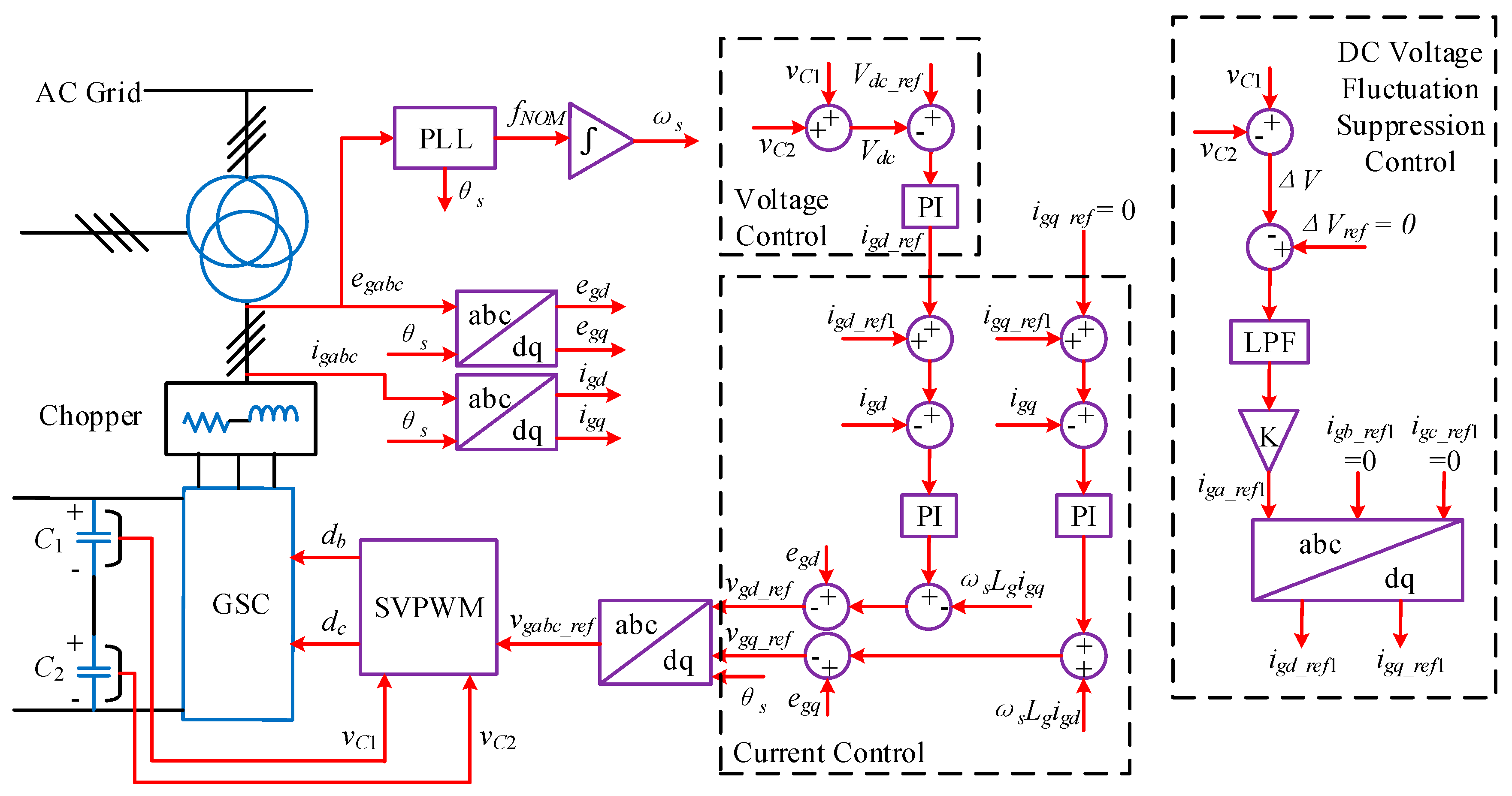
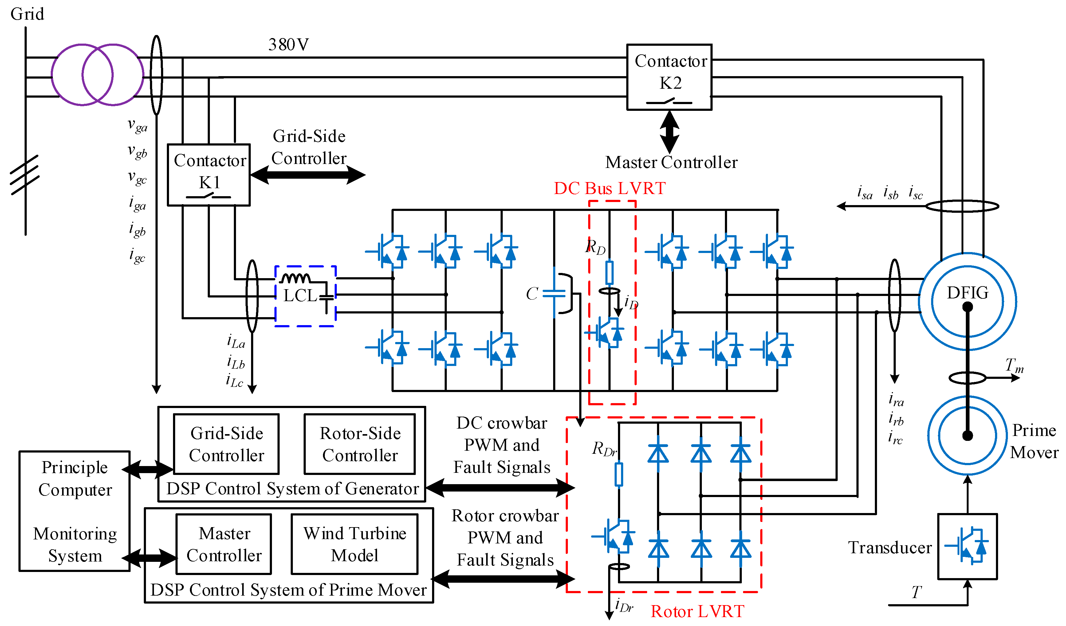
Figure 1. The stator of DFIG is directly connected to the grid, while the rotor is connected to the grid through a back-to-back power electronic converter, which is composed of a rotor-side converter (RSC) and a grid-side converter (GSC). Power electronic pulse width modulation (PWM) converters are crucial parts in DFIG-based wind power generation systems, while the fragility of the power electronic devices in these converters leads to several issues. According to [7], 21% of the faults in power converters are caused by breakdown of power electronic devices. For example, if one of the switches in a three-phase power converter is broken, normal regulation of power flows is lost. In this case, the corresponding doubly-fed induction generator-based wind turbine (DFIG-WT) has to disconnect from the grid [8,9]. For offshore wind turbines (WTs), maintenance is restricted because of bad weather conditions and high maintenance costs, in which case the faulty WT can stop working for several months [10]. Since the proportion of offshore wind farms in the EU is increasing due to abundant wind resources on the sea, along with the non-negligible status of wind energy in the near future, it is necessary to improve the fault-tolerant ability of WTs [5,10].
The four-switch three-phase (FSTP) topology is one of the most widely used fault-tolerant converter topologies since no surplus switches are required [11]. After one of the semiconductor switches breaks down and an open circuit is formed, the faulty phase is connected to the midpoint of the DC bus by splitting the DC-link capacitor [12,13]. Compared with the normal six-switch three-phase (SSTP) topology, the number of switches and parallel diodes decreases which reduces the cost and conduction losses. However, there are several shortcomings for FSTP converters. For examples, the voltage gain decreases and the increased current rating occurs when the output power remains the same, and the current in the faulty phase results in DC-link capacitor voltage deviation [12]. In addition, the voltage utilization rate is only half of that when applying an SSTP converter [13]. In order to improve the performance of an FSTP converter, substantial researches were carried out.
SSTP converters are widely applied in the fields of active power filters (APFs) and motor drives, and the fault-tolerant FSTP converters in these applications have been discussed in a variety of papers. Literatures [14,15,16,17] concentrated on different control strategies for FSTP induction motors (IMs). In [18,19,20,21], the researchers focused on the applications of FSTP topologies in brushless DC (BLDC) [18,21] and DC motors [19,20], however, the machines mentioned above are not usually applied in wind energy conversion systems. One of the commonly used generators in the wind industry is the permanent magnet synchronous generator (PMSG), and in [22,23,24] the authors studied PMSG drives in FSTP converters for WT applications, and fault tolerance was considered. However, the heavy weight and high cost of a PMSG are the main obstacles for its development in wind energy industries.
Compared with investigating the control strategies for FSTP converters, adjustments in PWM techniques influence the quality of the three-phase currents by a greater extent. An adaptive PWM strategy was proposed in [25] to decrease the degree of unbalance between voltages and currents, and sector identification was omitted in the algorithm. In [26], the researchers developed an optimized modulation approach for the post-fault PWM rectifiers to eliminate the DC voltage unbalance by minimizing capacitor currents. In addition, the DC-link capacitor current stress in the post-fault grid-connected three-phase rectifier is reduced by a space-vector-based hybrid PWM strategy in [27]. Moreover, the zero voltage distribution in FSTP rectifier was studied for performance analysis [28] in terms of the AC current ripple, the common voltage (CMV) and the current stress on the DC-link capacitor. Although the modulation techniques and control strategies described in [25,26,27,28] are applicable in converters, the performance of DFIG-WTs with modified PWM techniques has not been studied.
In recent years, there are some references concentrating on fault detection and isolation techniques for DFIG-WTs. In [29], the authors proposed a fault-tolerant control method for various sensors used in DFIG. Although the response is fast, both the observer algorithm and hardware design are complex. The controllability of a DFIG-WT is maintained in [30] by using a passive resistance network when the grid voltage sags. The researchers in [31] proposed a nine-switch grid-side converter to seamlessly ride through different categories of grid faults, while fragility of semiconductor switches was not considered. System reconfiguration for a doubly fed induction machine (DFIM) was presented by applying FSTP topologies for GSC and RSC to sustain the normal operation of WT [32]. However, it utilized the method in [33] for eliminating the DC-link capacitor voltage distortion, and no further improvement in the PWM technique was conducted.
In DFIG-WTs, the main functions of GSC are keeping the DC-bus voltage steady, making the grid-side three-phase currents sinusoidal and controlling the output power factor. This paper aims to make the performance of the FSTP GSC acceptable for a DFIG-WT to constantly supply power to the grid with different external disturbances. Different from the modelling methods used in previous researches for either rectifiers [26] or inverters [25], bidirectional power flows should be taken into consideration for the modelling of FSTP GSC in DFIG-WT. Besides, compensation for capacitor voltage deviation has to be included since charging and discharging processes occur, respectively, for the two DC-link capacitors in some switching states, and the switching frequency should be limited in practice. In previous studies, the researchers either investigated only the performance of FSTP converters by modified modulation techniques and control strategies [12,13,25,26,27,28], or make comparisons between pre-fault and post-fault performances of the machine without further modifications in modulation techniques [32]. In addition, mathematical analysis on the relationship between the wind speed and the mechanical performance of FSTP GSC-based DFIG-WT is not available from the literatures. In this work, converter reconfiguration, simplified SVPWM technique, varying wind speed and grid voltage sags are considered to demonstrate the reliability of FSTP GSC based DFIG-WT, which have not been comprehensively analyzed in previous researches to the best of the authors’ knowledge.
The paper is organized in the following structure: in Section 2, modelling of the fault-tolerant FSTP GSC is illustrated according to two DFIG operational modes. The SVPWM technique is explained in Section 3 for FSTP GSC and it is simplified according to mathematical deductions. Control strategies and controller design of the proposed GSC in DFIG-WT are illustrated in Section 4. A system-level analysis is presented in Section 5, and the mechanical performance of the DFIG is explained with respect to wind speed change. Simulation results are reported in Section 6 with a discussion on the performance of both topologies for different external conditions. In Section 7, experimental results are illustrated to demonstrate the system reliability. In Section 8, conclusions are given.

2. FSTP GSC Modelling

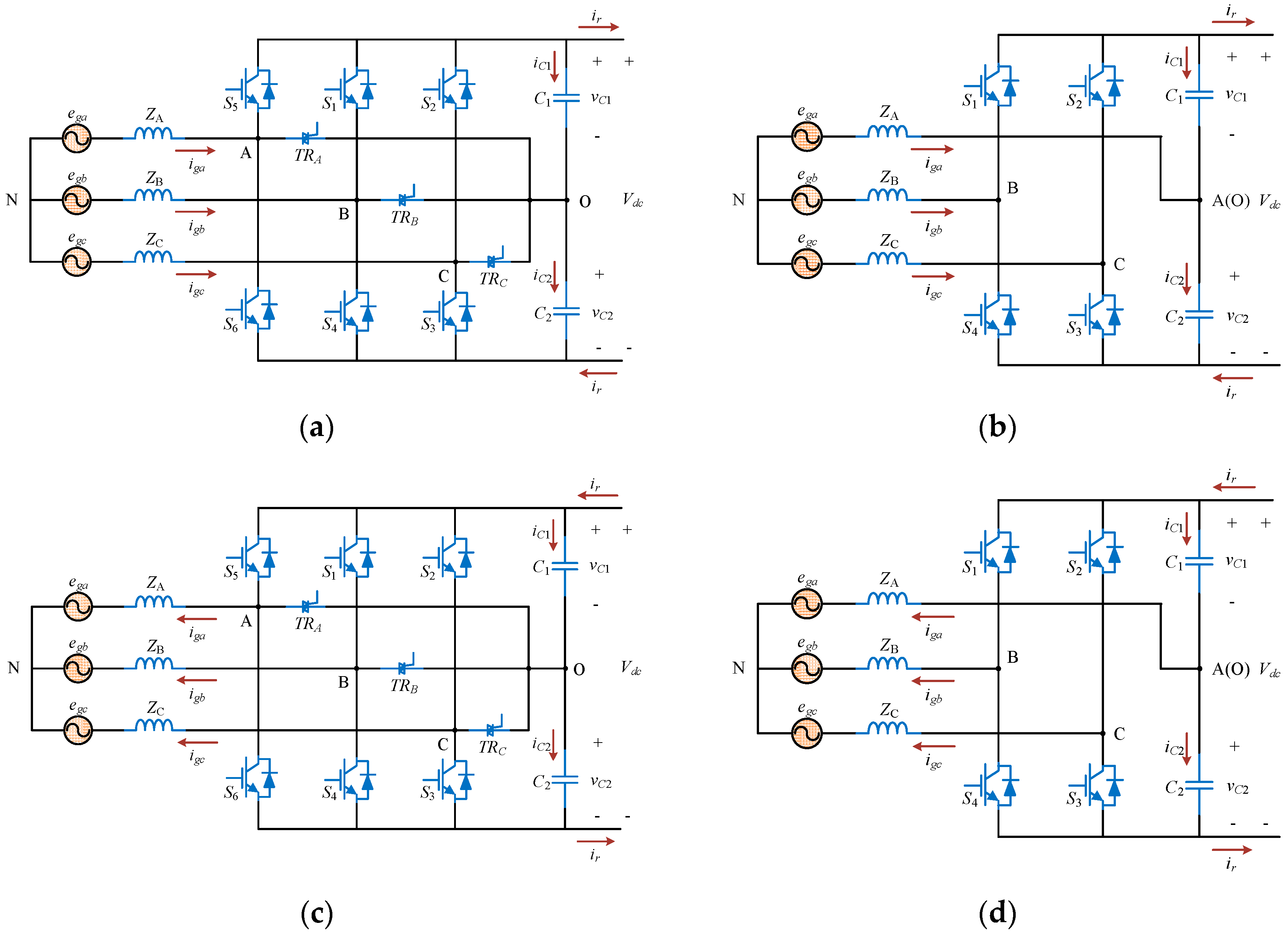
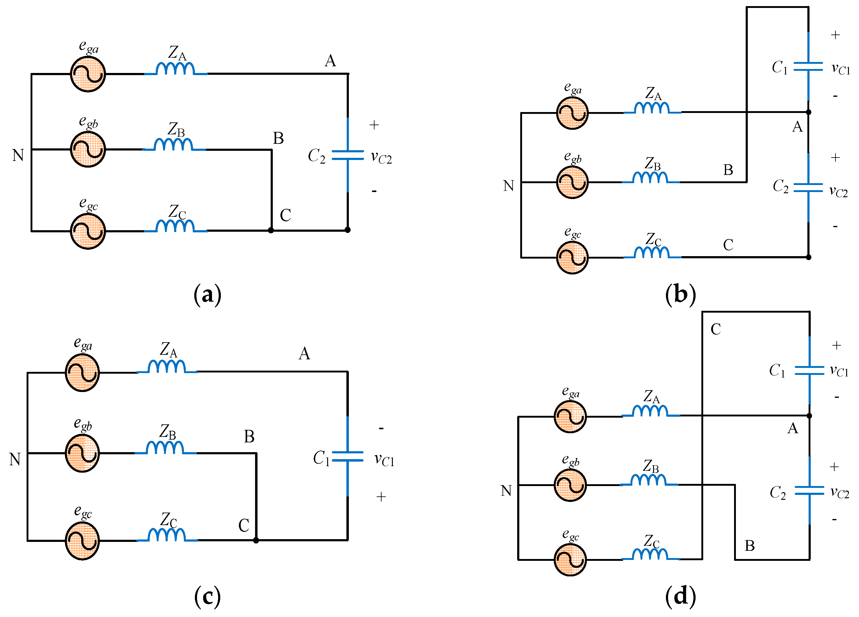
The fault-tolerant topologies for pre-fault and post-fault GSC under different operational modes are shown in Figure 2. Six IGBTs with parallel diodes (S1 to S6) are the switching devices. In this paper, the three-phase grid is assumed balanced (ZA = ZB = ZC). The DC-link capacitors C1 and C2 are usually identical (C1 = C2 = CDC) [26]. TRA, TRB and TRC are triacs, and the triac in the faulty phase is triggered and the faulty bridge arm is isolated by connecting the corresponding phase to the midpoint of DC bus. For example, when S5 or S6 breaks down, the equivalent FSTP converter circuit is shown in Figure 2b,d. With appropriate control strategies for the remaining four switches, normal operation of the converter can be maintained after the fault.
In this paper, the fault situation mentioned above is considered, whose faulty phase is phase A. When the fault happens in phase B or C, the situation is the same, which has been identified in [34]. The switching states of the rest switches (S1 to S4) are represented by 1 or 0, where 1 indicates on and 0 means off. The switches in the same bridge arm are always in the complementary states for each other, and the relationships can be expressed as shown below:
{ S 4 = 1 S 1 S 3 = 1 S 2
It is easier to distinguish the switching states of the bridge arms B and C by using the variables Sb and Sc. Sb = 1 denotes that S1 is on and S4 is off, and Sb = 0 represents the case that S1 is off and S4 is on. Sc = 1 indicates that S2 is on and S3 is off, and Sc = 0 means that S2 is off and 
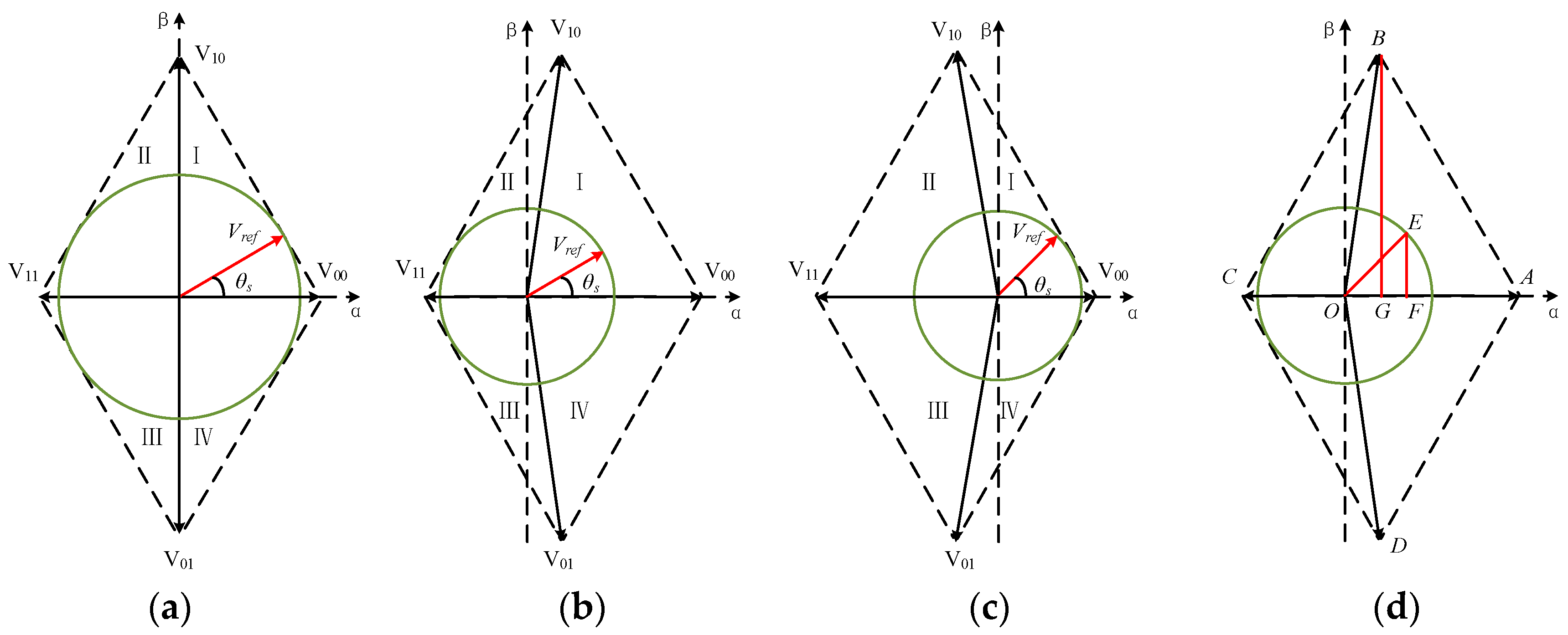
S3 is on. There are totally four combinations of the switching states of Sb and Sc, and four basic vectors (namely V00, V10, (V11 and V01) are used to develop a new SVM technique for the post-fault FSTP GSC. Equivalent circuits for an FSTP converter with different switching states are shown in Figure 3, and the values of three-phase grid voltages in an FSTP converter are displayed Table 1. The low-frequency model of an FSTP GSC is going to be analyzed according to the subsynchronous and supersynchronous operational modes of the DFIG-WT. The synchronous operational mode is not going to be discussed in detail since no AC current flow through the converter is presented in this mode.

2.1. Subsynchronous Operational Mode

Under the subsynchronous mode, the three-phase currents flow from the GSC to RSC to support the exciting magnetic fields in the rotor, and ωr is smaller than ωs in this case. The grid-side three-phase voltages can be derived as functions of switching variables Sb and Sc by using Kirchhoff voltage laws as shown below:
{ v A N = 1 3 v C 1 ( S b S c ) + 1 3 v C 2 ( 2 S b S c ) v B N = 1 3 v C 1 ( 2 S b S c ) + 1 3 v C 2 ( 2 S b S c 1 ) v C N = 1 3 v C 1 ( 2 S c S b ) + 1 3 v C 2 ( 2 S c S b 1 )
DC-link currents can also be expressed by Sb and Sc as:
{ i C 1 = S b i g b + S c i g c i r = C D C d v C 1 d t i C 2 = ( S b 1 ) i g b + ( S c 1 ) i g c i r = C D C d v C 2 d t
According to Kirchhoff current laws, the current in phase A is the difference between the upper and lower DC-link currents, which can be expressed as:
i g a = i C 2 i C 1
Substitute (3) into (4), the expression for iga is:
i g a = ( i g b + i g c ) = C D C d ( v C 2 v C 1 ) d t
The expression reveals that appropriate modulation and control of the currents in phase B and phase C can ensure the quality of the current in phase A. The difference between vC2 and vC1 is derived by performing integral on both sides of (5):
v C 2 ( t ) v C 1 ( t ) = 1 C D C 0 t i g a d t + v C 2 ( 0 ) v C 1 ( 0 )
In (6), vC1(0) and vC2(0) are the initial values for vC1(t) and vC2(t). The contribution of iga to the voltage fluctuation depends on the value of the capacitance CDC, and the voltage fluctuation is eliminated if CDC is large enough.

2.2. Supersynchronous Operational Mode

When DFIG-WT operates in this mode, the three-phase current flows are from the RSC to GSC, which contributes to a part of power output to the grid, and ωr exceeds ωs. The expressions of the three-phase grid-side voltages are the same as those described in (2). The expressions for the DC-link currents are:
{ i C 1 = S b i g b S c i g c + i r = C D C d v C 1 d t i C 2 = ( 1 S b ) i g b + ( 1 S c ) i g c + i r = C D C d v C 2 d t
According to Kirchhoff current laws, the current in phase A is the difference between the upper and lower DC-link currents, while the direction of it is opposite to that in the subsynchronous operational mode, and the counterparts of Equations (4)–(6) in this mode are expressed as:
{ i g a = i C 1 i C 2 i g a = ( i g b + i g c ) = C D C d ( v C 1 v C 2 ) d t v C 2 ( t ) v C 1 ( t ) = 1 C D C 0 t i g a d t + v C 2 ( 0 ) v C 1 ( 0 )
From (8), it can be observed that these equations are derived by replacing iga with (−iga) for (4)–(6). The expressions for the difference between the capacitor voltages for two different operational modes of a DFIG-WT both indicate that by adding a proper DC value to the grid current in phase A, the voltage deviation is likely to be suppressed.

3. Modulation Technique

3.1. SVPWM in FSTP Converter

To generate three-phase sinusoidal currents, sinusoidal pulse width modulation (SPWM) strategy is usually used due to its simplicity. However, as a voltage difference exists in the DC bus for an FSTP GSC, the traditional method of calculating the modulation index to generate the three-phase output control signals is not applicable. Therefore, a space vector pulse width modulation (SVPWM) technique is applied in order to obtain an ideal circular reference voltage vector locus. By using SVPWM technique, fewer distortions are produced in the current waveforms, and the utilization rate of the DC-bus voltage is increased compared to SPWM technique [35]. In the proposed SVPWM technique for an FSTP converter, the reference voltage vector can be located in four sectors, instead of six for a SSTP one. There are four different switching states (V00, V10, V11 and V01, where V10 and V01 have 3 times the magnitudes of V00 and V11), and there is no zero voltage vector for an FSTP converter. To create equivalent zero voltage vectors for modulation purpose, there are generally three ways which are using two opposite small-amplitude vectors (SVSVM), using two opposite large-amplitude vectors (LVSVM) and using the nearest three vectors (NTSVM). The other option to derive a reference voltage vector is distributing appropriate time for all the four basic vectors. In this paper only three out of the four vectors are chosen to combine the reference voltage vector in order to reduce switching losses for IGBTs. The distribution of the basic vectors in αβ stationary reference frame is shown in Figure 4. When the voltages on the upper and lower capacitors are not equal, the utilization rate of the DC-bus voltage decreases, which is indicated as a smaller circle in Figure 4b,c. According to [12], the relationship between the amplitude of the reference voltage and the DC-link voltages are:
V r e f = 1 3 min ( v C 1 , v C 2 )
If the DC-link capacitors C1 and C2 are large enough, the upper and lower voltages vC1 and vC2 are assumed equal, which is the case depicted in Figure 4a. Although the DC-link voltages are maximally used in this case, the efficiency is only half of that in SSTP converter topology, and the value of the DC-bus voltage has to increase to make sure the converter operates normally. Therefore, elimination of DC-link voltage unbalance is important to prevent the DC-link capacitors from enduring extremely large voltages.

3.2. Realization of the Simplified SVPWM Technique for FSTP GSC

Compared with the SVPWM technique used in an SSTP converter, there is no instinctive zero vector for the one applied in an FSTP one. In this case, apart from the two basic voltage vectors which defines the sector that the reference voltage vector locates in, another basic voltage vector should be chosen to act as an equivalent zero vector. There are three methods which are SVSVM, LVSVM and NTSVM that only apply three basic voltage vectors. For SVSVM, two basic voltage vectors with small amplitudes are used to generate the equivalent zero vector: V00, V10 and V11 in sectors I and II; V00, V11 and V01 in sectors III and IV. For LVSVM, two basic voltage vectors with large amplitudes are applied in the process of equivalent zero vector generation: V00, V10 and V01 in sectors I and IV; V11, V10 and V01 in sectors II and III. For NTSVM, three nearest basic voltage vectors are used, and the process is relatively complex since each sector should be divided into two parts to judge the nearest vectors for a particular case. The reference values for the three-phase AC voltages on the GSC are expressed as shown below:
{ v A N _ r e f = V m cos ( θ s ) v B N _ r e f = V m cos ( θ s 2 π 3 ) v C N _ r e f = V m cos ( θ s + 2 π 3 )
Take the case of vC1 < vC2 as an example, and the reference voltage vector is assumed to be located in sector I. The situation is to be analyzed and the duty ratios of three basic vectors will be calculated based on Figure 4d. OA, OB, OC and OD represent the vectors V00, V10, V11 and V01 respectively. In this case, OE is the reference voltage vector, and its components on α and β axes are OF and EF respectively. If SVSVM is used for synthesizing OE, then the basic voltage vectors to be used are V00, V10 and V11. In addition, the time distributed to the vector V11 counteracts part of the time used for V00 which forms the equivalent zero vector. OG and BG are separately α and β components of OB, which is the vector V10. Considering the situation in a switching period Tsw, the following relationships can be derived:
{ O F = O A × d 00 O C × d 11 + O G × d 10 E F = B G × d 10 / 3 1 = d 00 + d 10 + d 11
According to the values listed in Table 1, the magnitude of OA, OC, OG and OB are easy to obtain. The values of OF and EF are:
{ O F = v A N _ r e f E F = v B N _ r e f v C N _ r e f 3
By combining (11) and (12), the duty ratio for each basic voltage vector is derived, and then the duty ratios for the two remaining bridge arms are calculated. Based on the conclusions obtained in [13] and double check by the authors, the results of db and dc do not change with variations of either the sector or modulation method. In this case, sector identification and real-time calculation of trigonometric functions are not required, and the process of PWM becomes simple. The values of db and dc are derived as shown below:
{ d b = v C 2 v A N _ r e f + v B N _ r e f V d c d c = v C 2 v A N _ r e f + v C N _ r e f V d c
The duty ratio for the equivalent zero vector can be calculated as:
d 0 = 1 d b d c
The value of d0 is supposed to be positive, otherwise overmodulation occurs and it deteriorates the performance of the PWM converter.

4. Control of GSC

The back-to-back converter is divided into two parts, which are GSC and RSC, and the control strategy of GSC based on FSTP topology is illustrated in this section, as is shown in Figure 5.

4.1. Dual-Loop Control Strategy of GSC

The main functions of GSC in a DFIG-WT are keeping the DC-bus voltage steady, maintaining the grid-side three-phase currents sinusoidal and controlling the output power factor. If the active power on the AC side and that on the DC side of the converter are balanced, stability of the DC-bus voltage is guaranteed. The GSC controller system is divided into two parts in general, which are the outer-loop voltage controller and the inner-loop current controller.

4.2. PI Current Controller Design

The dq components of the voltages on the AC side of GSC based on the grid voltage oriented d axis are expressed as:
{ v g d = E m L g d i g d d t R g i g d + ω s L g i g q v g q = L g d i g q d t R g i g q ω s L g i g d
From the equations above, apart from the influences of vgd and vgq on dq currents, the effects of the current coupling items ωsLgigd and ωsLgigq, the voltage drop Rgigd and Rgigq, and the grid voltage Em are also included. To effectively control the dq components of the grid currents, the coupling between the currents and disturbance from the grid voltage needs to be eliminated by the proposed control method. The PI current controller is designed in the way described by the following equations:
{ L g d i g d d t = L g d i g d _ r e f d t + K p d ( i g d _ r e f i g d ) + K i d ( i g d _ r e f i g d ) d t L g d i g q d t = L g d i g q _ r e f d t + K p q ( i g q _ r e f i g q ) + K i q ( i g q _ r e f i g q ) d t

4.3. PI Voltage Controller Design

Design of the PI DC voltage controller is similar to that of the PI current controller:
i C = C d V d c d t = C d V d c _ r e f d t + K v p ( V d c _ r e f V d c ) + K v i ( V d c _ r e f V d c ) d t

4.4. Suppression of DC Voltage Deviation

The fluctuation between the DC-link voltages is caused by the sinusoidal characteristic of the current in phase A, and this factor should be considered in the current control process as illustrated in Figure 5. A second-order low-pass filter is used to exclude the disturbances from high-order in iga. In the control process, the transient DC reference current in phase A (iga_ref1) is derived by using a proportional controller, and its dq components are considered to amend the reference dq current values.

5. DFIG-WT System

5.1. dq Model of DFIG

As a three-phase DFIG system has the characteristics of high order, strong coupling, multiple variables, nonlinearity and time variation, the decoupling process is required, and it is usually obtained by applying Clarke’s and Park’s Transformation [36]. By expressing the DFIG model in an arbitrary rotating dq reference frame, independent control of active and reactive power by controlling stator and rotor currents on dq axes is completed. In this paper the grid voltage orientation (GVO) is used and all the rotor-side parameters are referred to the stator side.
The voltage equations are expressed as:
{ V s d q = R S i s d q + d φ s d q d t + j ω s φ s d q V r d q = R r i r d q + d φ r d q d t + j ( ω s ω r ) φ r d q
The magnetic fluxes are expressed by currents on the stator and rotor as follows:
{ φ s d q = L s i s d q + L m i r d q φ r d q = L r i r d q + L m i s d q
A key factor to be determined in the operation of a DFIG is the electromagnetic torque Te, which is calculated by:
T e = n p ( φ s d i s q φ s q i s d )
By substituting (19) into (20), Te can be derived by:
T e = n p L m ( i r d i s q i r q i s d )
The mechanical model of DFIG can be described by the following formula:
T e T m = J d ω m d t
As the machine works as a generator, the values of Te and Tm are both negative in this case, meaning that the turbine drives the rotor and delivers power to the grid.

5.2. Wind Turbine Model

The rotor of DFIG is driven by the shaft connected to the wind turbine, and the input power can be derived according to aerodynamics of the turbine as shown below:
P v = 1 2 ρ S w v w 3
The power absorbed by the turbine is represented by the multiplication of Pv and the wind power coefficient Cp:
P o = P v C p
The expression of the wind power coefficient is given as:
C p = c 1 { c 6 λ + c 4 c 3 ( 2.5 + β p i t c h ) + c 2 [ 1 λ + c 7 ( 2.5 + β p i t c h ) c 8 1 + ( 2.5 + β p i t c h ) 3 ] exp { c 5 [ 1 λ + c 7 ( 2.5 + β p i t c h ) c 8 1 + ( 2.5 + β p i t c h ) 3 ] } }
where c1c8 are the parameters for Cp, and their values are displayed in Table 2. The tip speed ratio can be represented by:
λ = v b v w = R b ω b v w
When no external disturbance is included, the wind speed remains at 15 m/s. After the wind speed fluctuation between 7 m/s and 15 m/s is considered, the average wind speed declines. To keep the value of Cp constant, from (25) and (26), the blade rotating speed ωb has to decrease, and it will fluctuate around a value smaller than the rated one. Because of the large inertia of the turbine, the blade angular speed ωb varies slowly. In a WT system, the mechanical rotor speed ωm is equal to ωb times the rate of speed increase N provided by the gearbox:
ω m = N ω b
The torque produced by the wind turbine Tt is derived by dividing Po by ωb, which is:
T t = P o / ω b
By combining (23)–(26) and (28), the expression of Tt is derived as:
T t = 1 2 ρ S w R b v w 2 c 1 c 6 + c 4 c 3 ( 2.5 + β p i t c h ) + c 2 [ 1 R b ω b 2 v w + c 7 ( 2.5 + β p i t c h ) c 8 1 + ( 2.5 + β p i t c h ) 3 ] 2 exp { c 5 [ 1 R b ω b v w + c 7 ( 2.5 + β p i t c h ) c 8 1 + ( 2.5 + β p i t c h ) 3 ] } ρ S w v w 3 c 1
As c1c6 is an extremely small value, the first term in (29) can be neglected. In addition, since βpitch is much larger than 2.5 when wind speed is high, and c8 is small, the term c 8 1 + ( 2.5 + β p i t c h ) 3 can be eliminated. Besides, as the value of c7 is only 0.08, the term c7(2.5 + βpitch) is omitted. By substituting the values of c1 to c8 into (29) and with the assumption above, the following approximate equation is obtained:
T t 0.645 ρ S w ( 6 0.4 β p i t c h ) v w 3 + 116 v w 4 R b ω b 2 2 exp ( 21 v w R b ω b )
In transient states, only the wind speed vw and pitch angle βpitch are variables, while other parameters are assumed to be constants. The shaft torque Tm is proportionally related to the turbine torque Tt. Based on (22) and (30), the value of Te has to change with the wind speed fluctuation to keep the rotor speed steady.

6. Simulation Results and Discussion

In this paper, the detailed DFIG wind farm model in Matlab/Simulink 2016a is used as the basis for simulation. Reconfiguration of GSC is done by connecting phase A to the midpoint of DC bus. Details of the parameters are displayed in Table 3. The values of proportional and integral gains for different PI controllers are shown in Table 4. Three different operation environments are considered for both the SSTP and FSTP GSC based DFIG-WTs, which are the situations without external disturbance, with fluctuating wind speed, and with both fluctuating wind speed and grid voltage sag. When there is no external disturbance included, the wind speed is maintained at 15 m/s. For the second case, the 1.5 MW DFIG-WT operates under the condition that the wind speed keeps changing within the range of 7 to 15 m/s every 0.01 s. To further investigate the low voltage ride through (LVRT) ability of DFIG-WT with SSTP and FSTP GSCs, a low voltage period is considered from 0.02 s to 0.07 s, and during this period the voltage value decreases to half of the original value. The sampling time for the simulation is set as 5 μs.
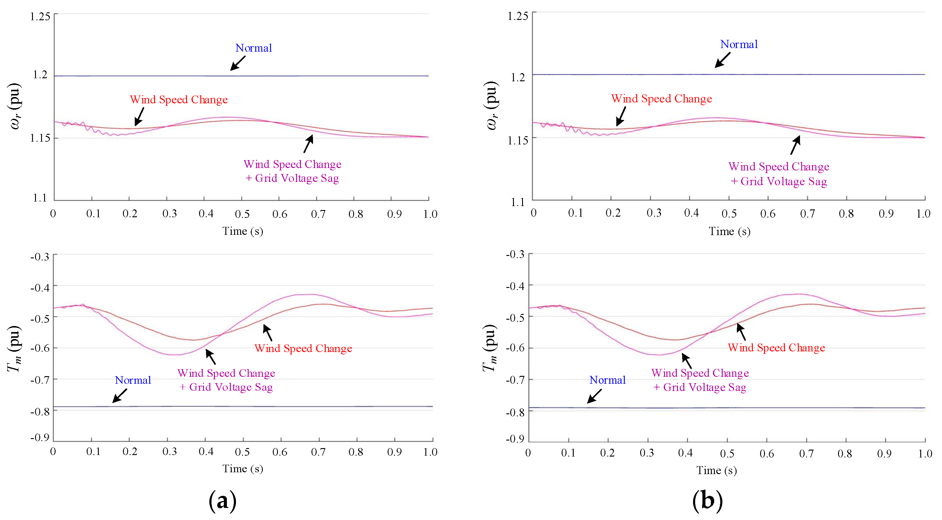
The rotor speed and mechanical torque under different operational situations for the pre-fault and post-fault GSC based DFIG-WT are displayed in Figure 6. The rotor speed remains at 1.2 pu when there is no external disturbance, while it decreases and fluctuates around a value over 1.15 pu after external disturbances are added. The results cater to the analysis in Section 4. For the mechanical torque, a stable value of about −0.8 pu is obtained when the wind speed is fixed at 15 m/s. Since the average wind power input decreases when the wind speed changes, the absolute value of the mechanical torque declines obviously with fluctuations as described in (27). With grid voltage sag, the grid currents have to increase because steady power output is to be kept, which increases the value of Te. Then the absolute value of Tm increases as displayed in Figure 6 to guarantee a steady rotor speed. After 0.3 s, its value starts to return to the original one. From Figure 6 it can be observed that the mechanical performance of the system is not affected by reconfiguration of GSC, which validates the feasibility of this fault-tolerant topology in DFIG-WT. To ensure the stability of DC-bus voltage and effective control of output power factor of the generator, the qualities of the three-phase grid current waveforms must be high enough.
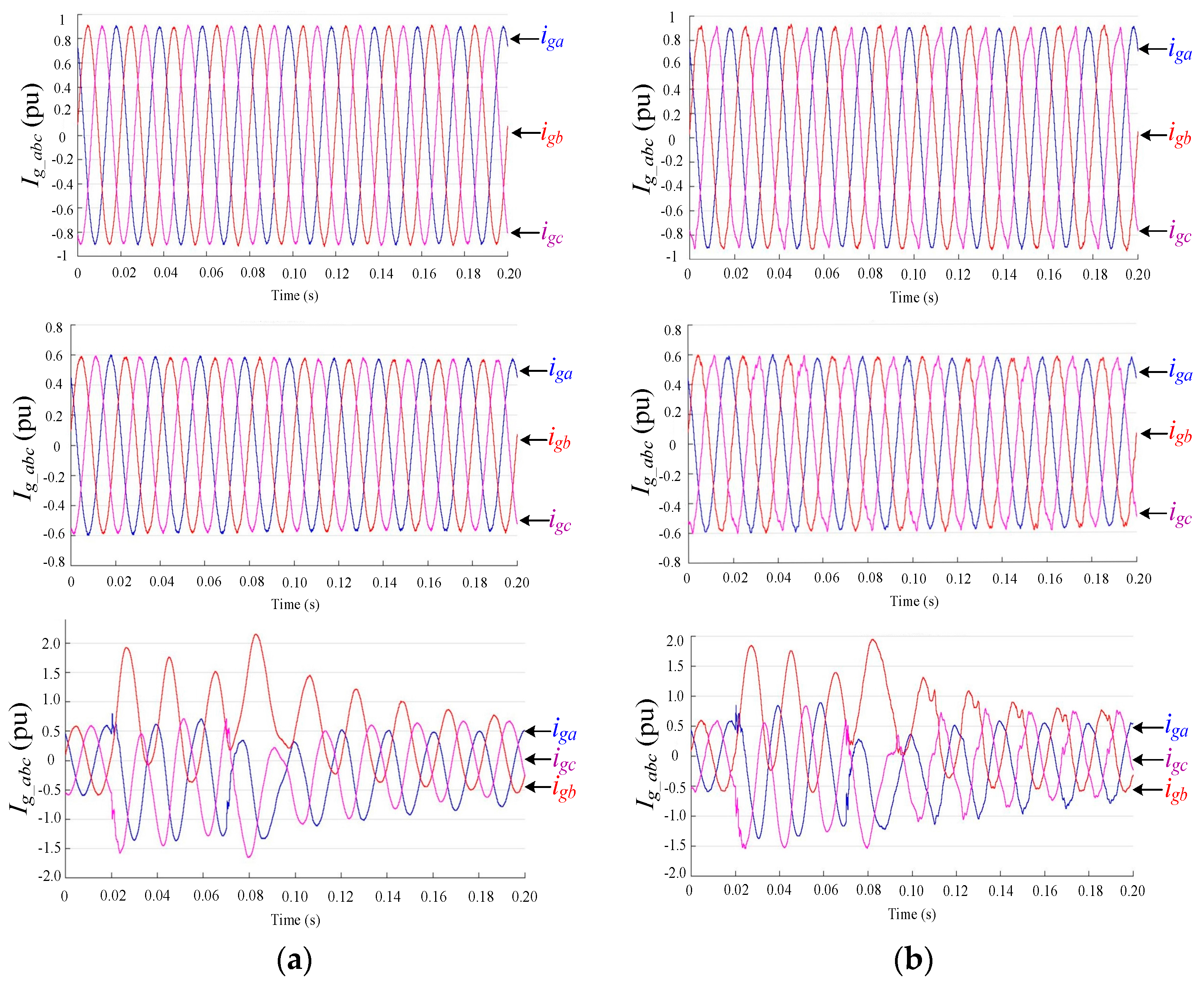
A comparison between the grid current waveforms for SSTP and FSTP GSC based DFIG-WTs in the three cases is carried out, which is displayed in Figure 7. When the wind speed is fixed at 15 m/s, the amplitudes of the three-phase grid currents are around 0.9 pu for both the SSTP and FSTP cases, and more distortions can be seen in the latter one. When wind speed fluctuation is considered, the qualities of current waveforms are deteriorated for both cases and the amplitudes fall to around 0.6 pu. After the grid voltage sag is included, obvious deviations of three-phase currents are presented, and the influence lasts for approximately 0.12 s after the sag is removed.
In order to analyze the quality of grid current waveforms in detail, Fast Fourier Transformation (FFT) analysis is conducted. The data derived from FFT analysis is shown in Table 5 and Table 6. From Table 5, it can be observed that the total harmonic distortion (THD) values for the grid currents in three phases before GSC reconfiguration is made are relatively low, which are all smaller than 1.5%. The point to be noticed is that all the statistics are the same for the second and third cases, indicating that the grid voltage sag does not essentially affect the grid current quality. As can be seen from Table 6, after FSTP GSC is used in the post-fault case, the magnitudes of fundamental components in three-phase grid currents are slightly smaller than their counterparts in SSTP GSC case, and the values of THD increase. However, the system is considered operating normally as the values are all lower than 5% (the maximum allowed THD for grid currents) [37]. In addition, when this post-fault FSTP GSC topology is used, the quality of the grid currents is not affected by the grid voltage sage. Furthermore, the current distortion in phase A is the least among three phases for each situation, which demonstrates the advantage of applying split DC-link capacitors in this topology. From these results, the validity of the proposed SVPWM technique is proved since the reliability of the system is good enough when facing both wind fluctuation and grid voltage sag conditions.
In Figure 8, Figure 9 and 
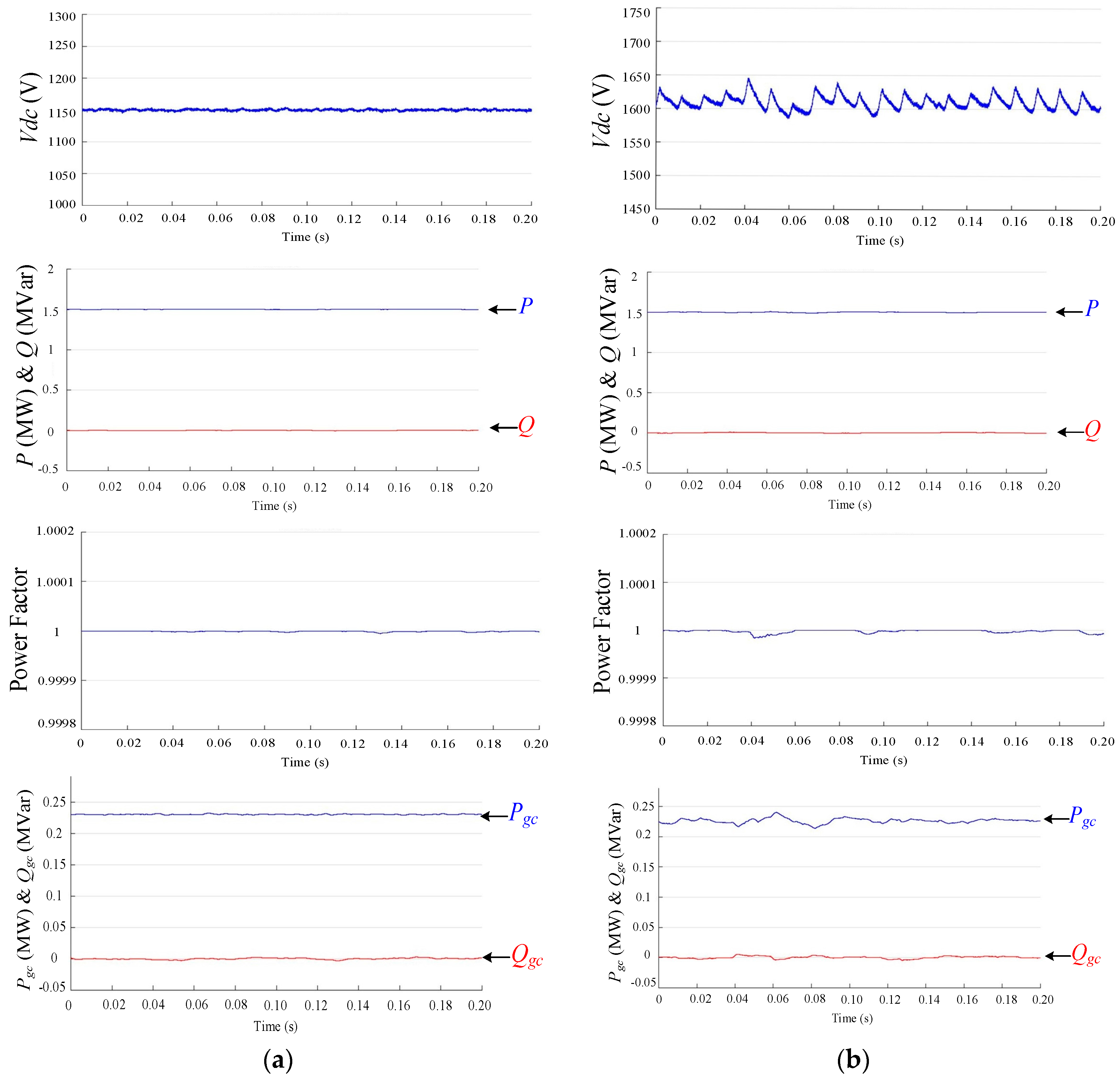
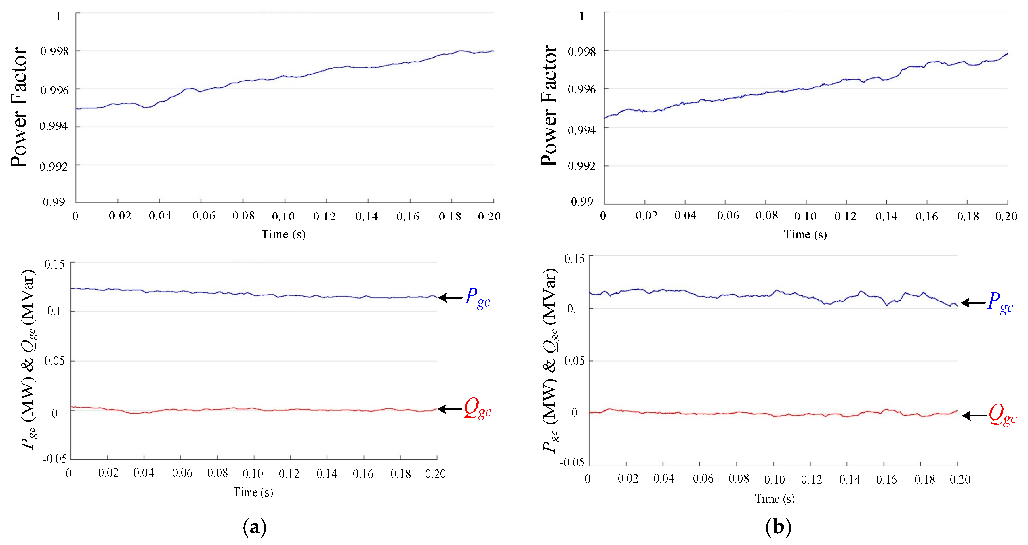
Figure 10, the DC-bus voltage, active/reactive output power, output power factor, and active/reactive power from GSC are illustrated under the three cases mentioned above to further investigate the performance of FSTP GSC based DFIG-WT, with comparison to the SSTP one. Under the circumstance without external disturbance, as depicted in Figure 8, although obvious fluctuations are introduced for the DC-bus voltage and the active/reactive power from the GSC for the FSTP case, the total output power and its power factor are almost not influenced. In 
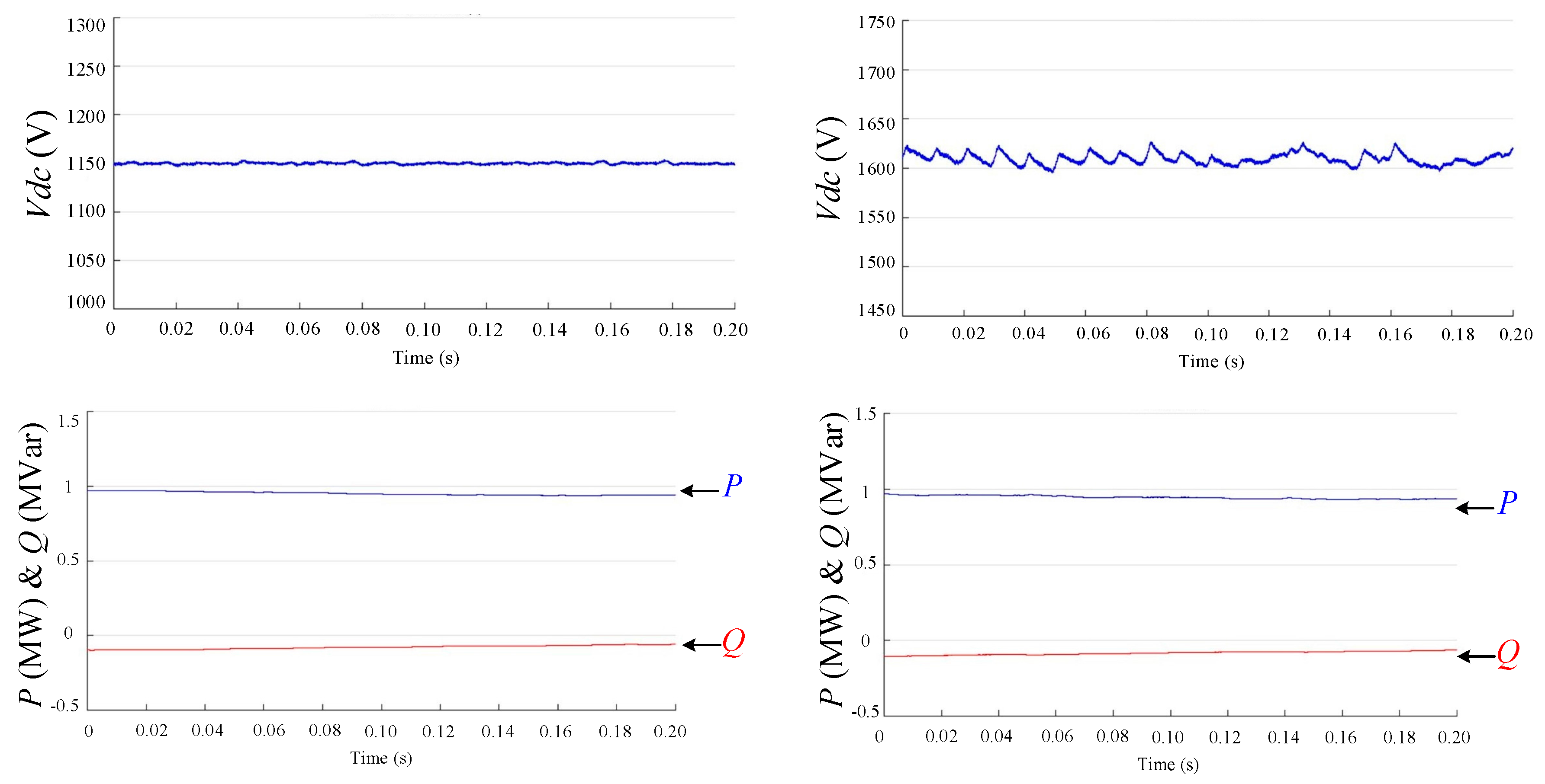
Figure 9, the performance analysis is conducted when the wind speed is fluctuating between 7 m/s and 15 m/s. Compared with the situation in the normal case, the fluctuation of DC-bus voltage is even smaller. Since the efficiency of absorbing wind energy decreases, less power output is to be produced, which reduces the voltage stress on the DC bus. From this point of view, the post-fault FSTP GSC topology is more suitable for DFIG-WTs operating with varying wind speed, which is a situation similar to a real one. The total and grid-side active powers are reduced, and the output power factor decreases slightly for both SSTP and FSTP GSC based DFIG-WTs in this case. The situation with grid voltage sag along with changing wind speed is illustrated in 
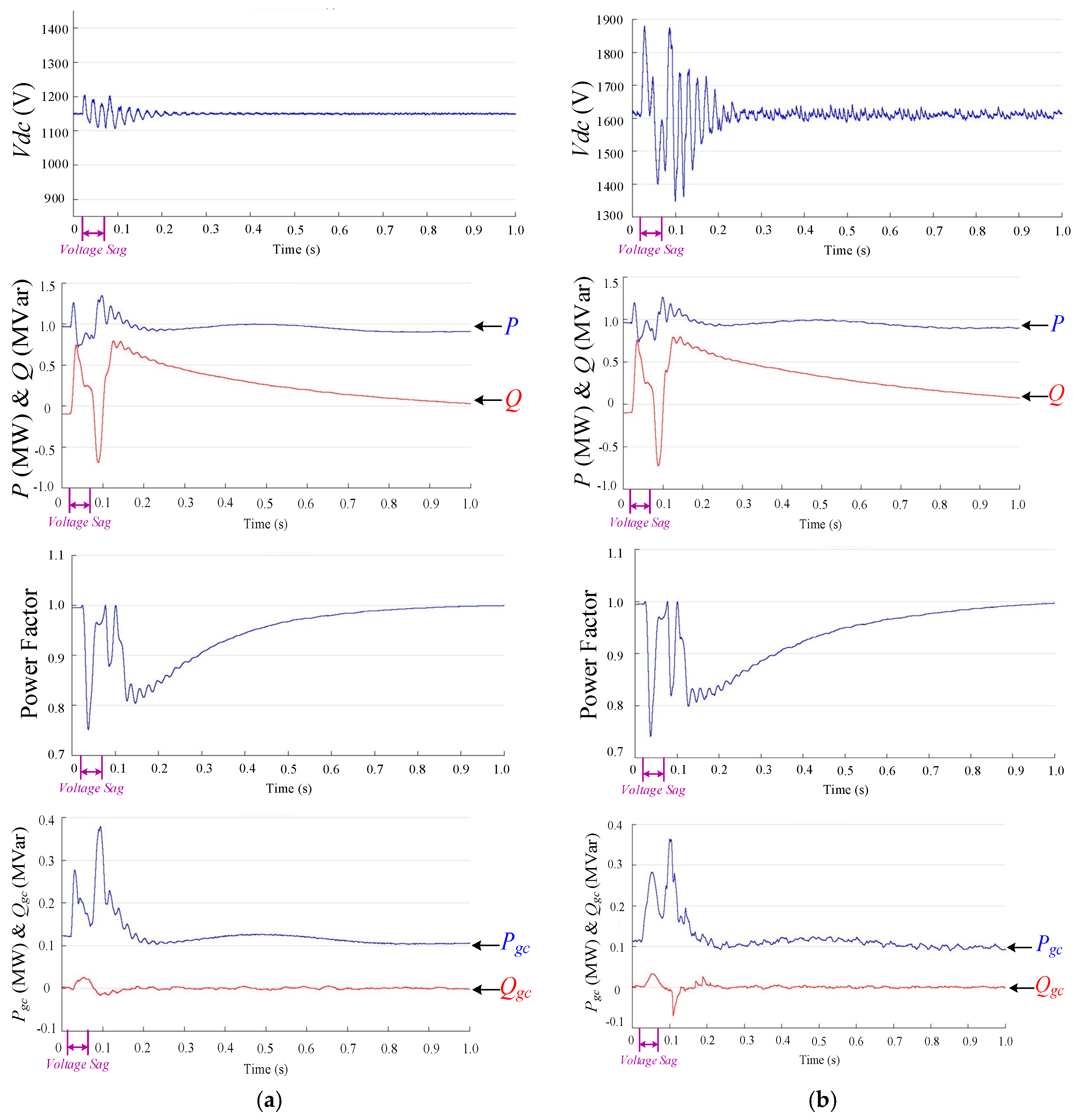
Figure 10, and the performances of the two different GSC topology based DFIG-WTs are similar in terms of the power factor. However, distinct fluctuation of DC-bus voltage is displayed for almost 0.2 s for the FSTP case. If the grid voltage fault lasts for a long period of time, it may cause damage to the capacitors. While the proposed FSTP GSC is robust to short-term grid voltage sags, which are more commonly encountered than the long-term ones.
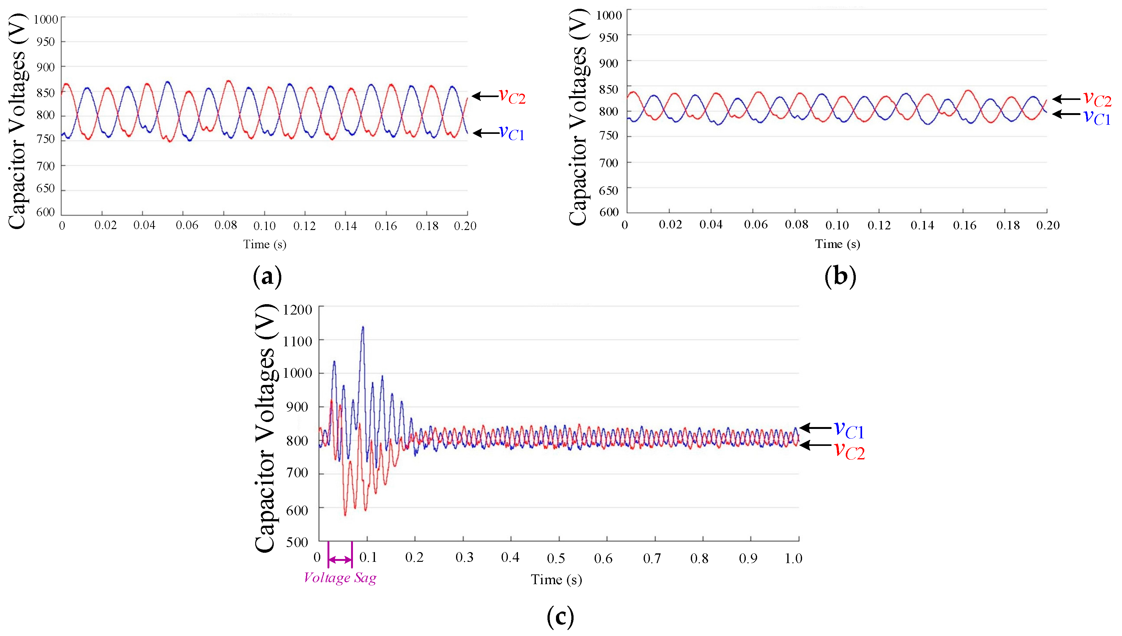
The application of FSTP GSC topology induces capacitor voltage imbalance, and suppression of the voltage difference is required to avoid extremely large voltages on DC-link capacitors. By using the DC voltage difference suppression controller, the difference between the upper and lower capacitor voltages is maintained within an acceptable range. From Figure 11, better performance of the controller is derived when the wind speed fluctuates than that with a constant wind speed at 15 m/s, which means constantly high wind speed deteriorates its performance. When short-term grid voltage sag is considered, distinct voltage deviation is observed. After 0.2 s, the performance returns back to the normal state and the system continues to work properly.

7. Experimental Results

Experimental verification of the fault-tolerant capability of a down-scaled 2 kW YSF112M-4 DFIG is performed in this section. The experimental platform structure is illustrated in detail in 
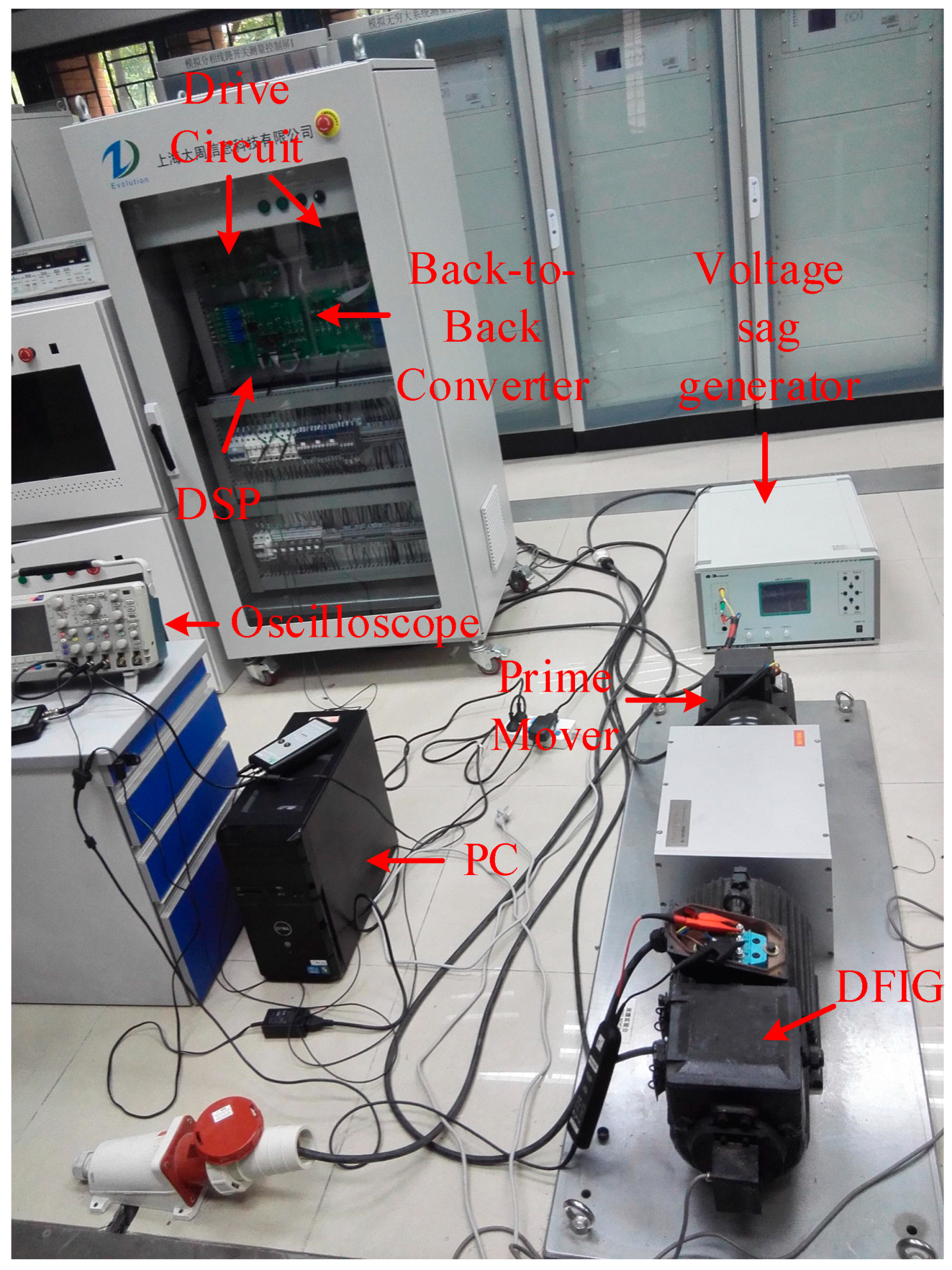
Figure 12, and a photograph of the experimental setup is displayed in Figure 13. All the equipment on the experimental platform is manufactured and provided by Shanghai Gcevolution Information Tech. Co. Ltd. in Shanghai, China.
The rated three-phase line voltage is 380 V with 50 Hz as its nominal frequency, and the rated rotor speed is 1500 rpm. The number of poles is 4. A CMTP180M4-50 PMSG rated at 2.3 kW is employed as the prime mover to drive the DFIG. The control scheme of the grid-connected DFIG is implemented on a DSP TMS320F28335 controller. The product model of the three-phase back-to-back converter is DZC02KDF with precharge and discharge circuits. In the experiments, the rotor speed is set to 1500 r/min (1 pu) and the DFIG works in the synchronous operational mode. The filter frequency is 200 MHz. In the experiments the stator line voltage, stator phase current and rotor phase current are measured to validate the fault-tolerant ability of the system. All the signals are derived with the unit of volts. The actual value of stator line voltage can be derived by multiplying the measured value by 500. For the current measurement, 2 mV in the measure value corresponds to 1 A in the actual value, so the actual stator and rotor phase currents are obtained by multiplying the measurement by a coefficient of ½ (A/mV). Enlargement of each waveform derived in the experiments is put at the right-hand side of the original waveform to illustrate the change in the corresponding value at the moments of fault and recovery.
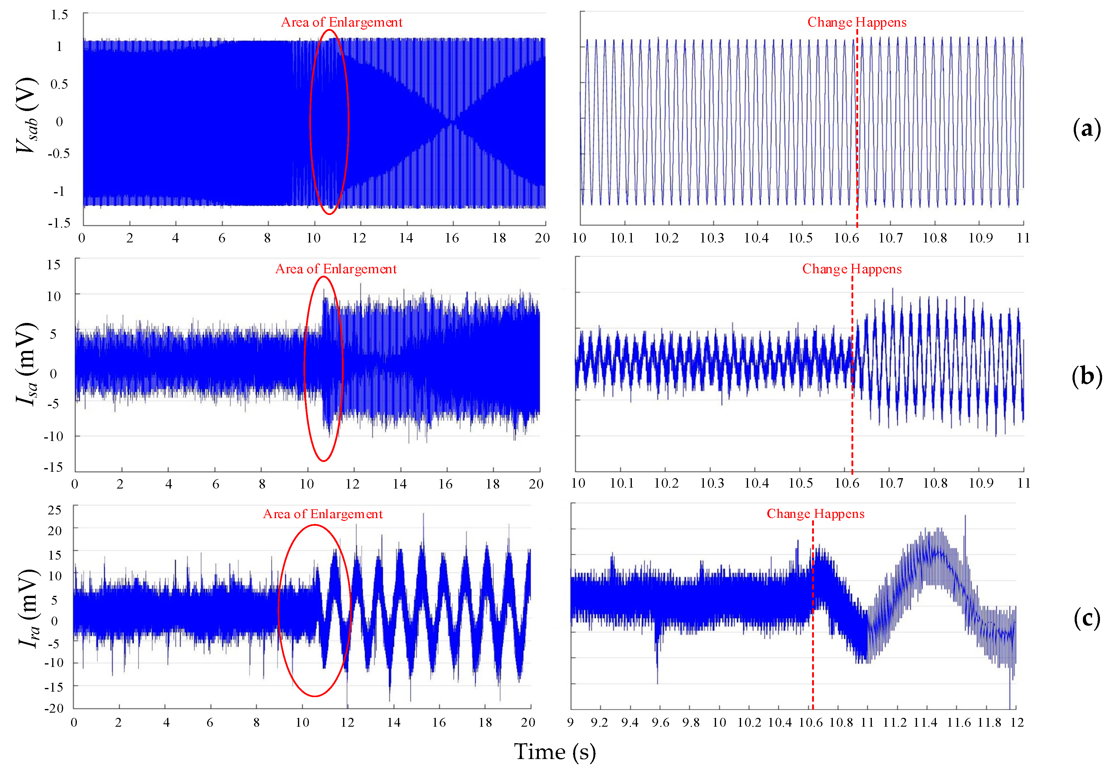
In the first experiment, the stator active power Ps steps from 500 W to 1 kW at time t = 10.625 s, and the sampling interval is 160 μs. From Figure 14 the stator line voltage between phases A and B increases a little bit and keeps good waveform quality. The amplitudes of stator and rotor phase A currents both rise to approximately twice of the original value. Although a few spikes are observed, the overall performance is excellent as the stability of waveforms is guaranteed.
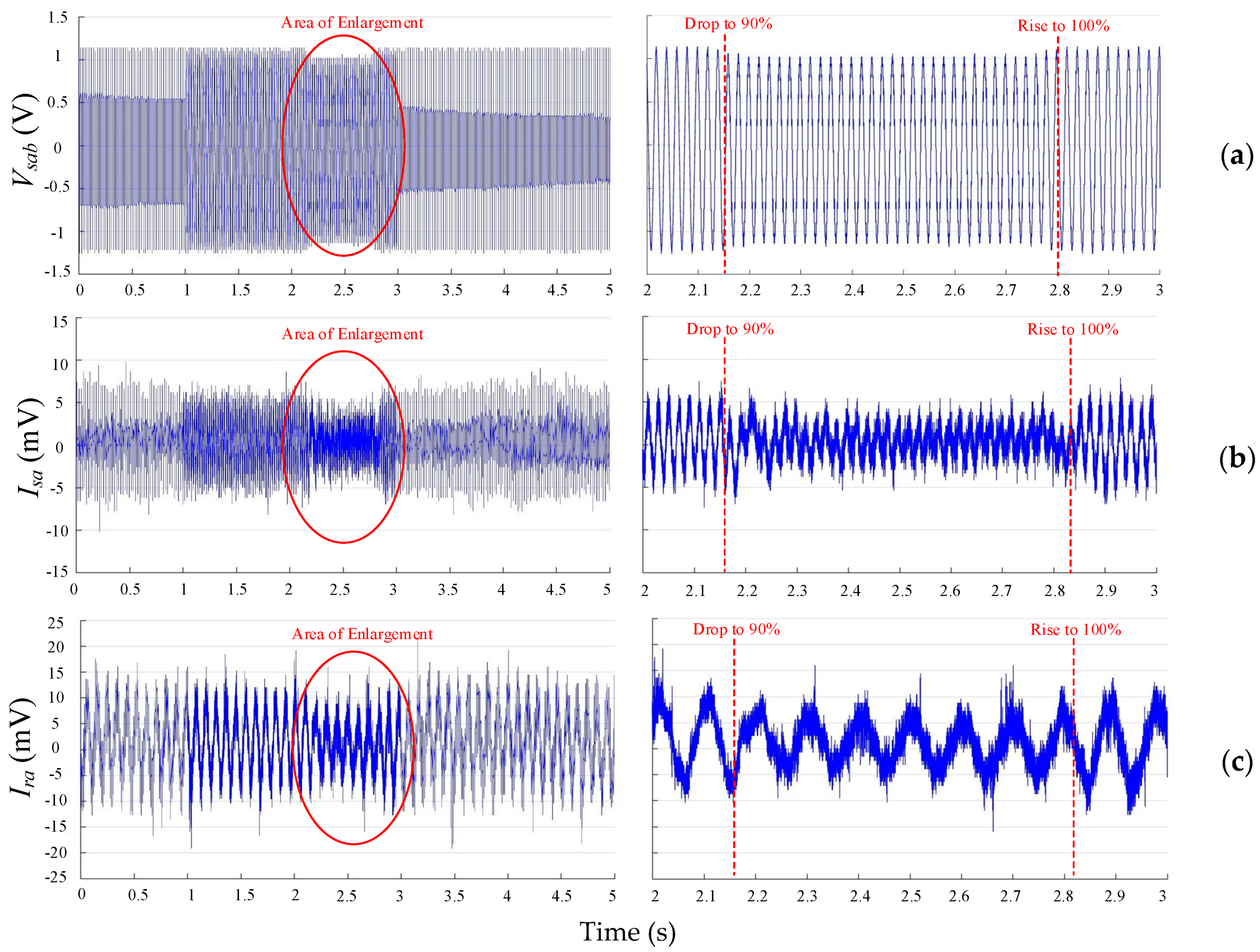
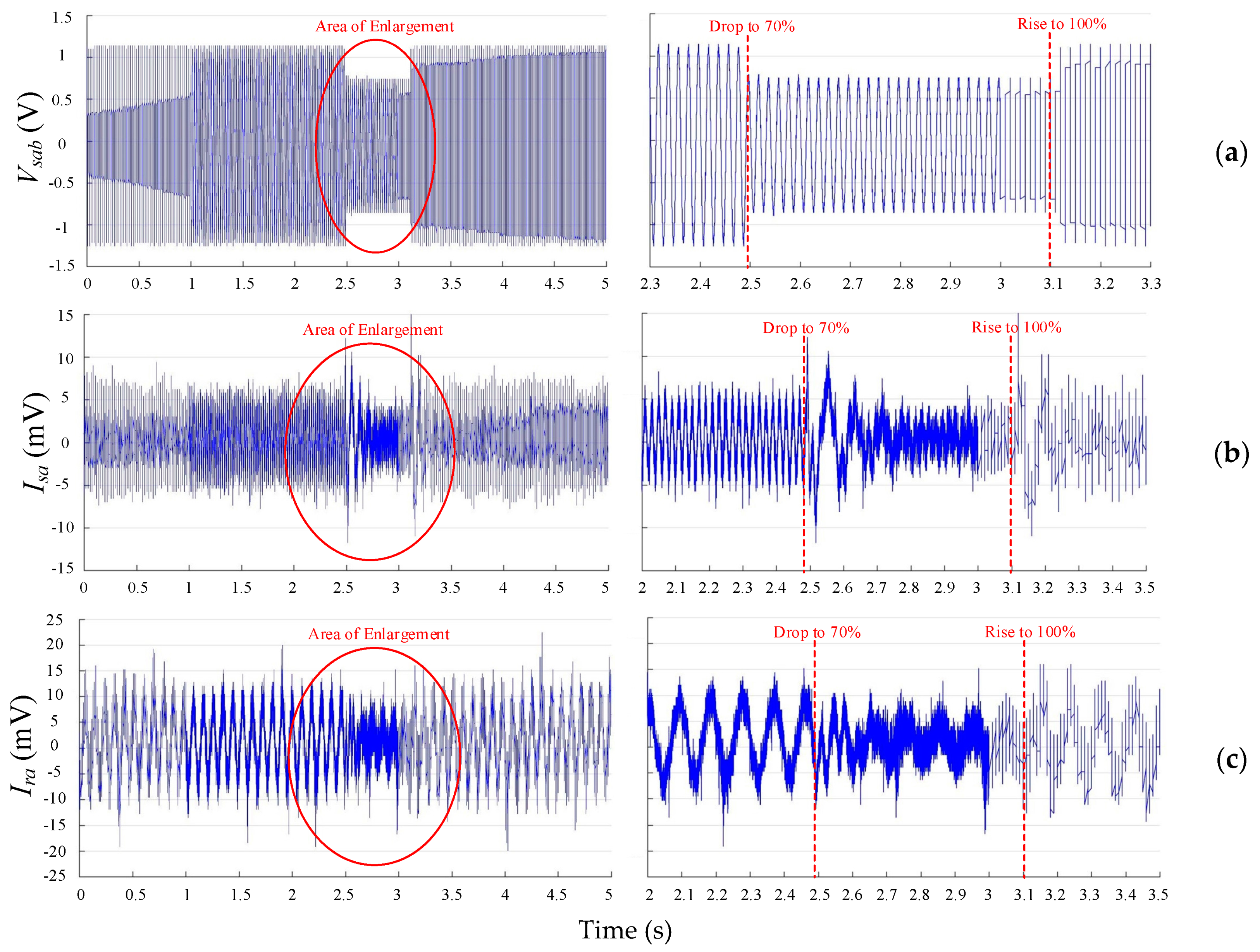
The second experiment focuses on the effect of grid voltage sag on the performance of DFIG, with the sampling interval of 80 μs. At first, the grid voltage drops to 90% of the original value and lasts for 0.625 s, and the experimental results are illustrated in Figure 15. From the results, it can be seen that the decline of stator and rotor currents in phase A is presented during the period of voltage sag, while they return back to the normal state instantly when the voltage sag ends. Then a further grid voltage drop to 70% of the original value is performed, and the results are depicted in Figure 16. The performance in this case is similar to the previous one, although obvious spikes in the stator phase current are presented at the beginning and ending of the voltage sag period.

8. Conclusions

This paper investigated the fault-tolerant operation of a DFIG-WT by using FSTP GSC with a simplified SVPWM technique by eliminating sector identification and complex trigonometric calculations. Wind speed variation between 7 m/s and 15 m/s was considered in the external disturbances. In addition, three-phase grid voltage sags were taken into account to test the fault-tolerant ability of the proposed topology. According to the bidirectional power flow characteristic for the back-to-back converter of DFIG, the modelling of FSTP GSC was completed with DC-bus midpoint current flow analysis. The difference between the capacitor voltages was suppressed with an appropriate control strategy. Furthermore, a system-level analysis was performed, and an approximate expression of the turbine torque was derived to investigate the relationship between wind speed variation and the mechanical performance of DFIG-WT. Finally, the proposed FSTP GSC based DFIG-WT was demonstrated to have acceptable performance even if different external disturbances are added. From the simulation results:
(a)
Both the rotor speed ωr and mechanical torque Tm fluctuated around smaller magnitudes after wind speed fluctuation was added. The fluctuation of Tm is strongly related to the approximate expression of turbine torque. The mechanical performance of FSTP GSC-based DFIG-WT is almost the same as that of SSTP one.
(b)
The quality of three-phase grid current waveforms is good enough for both FSTP and SSTP GSC- based DFIG-WTs under different operational environments as the THD of each phase current does not exceed 5%. Grid voltage sag has no effect on THD of grid currents for both topologies.
(c)
The DC-bus voltage increases after reconfiguration of GSC, and ripples are introduced. However, the system can still work properly, even when a short-period grid voltage sag is considered. Moreover, the stability of DC-bus voltage is better for FSTP GSC when the wind speed fluctuates between 7 m/s and 15 m/s compared to the constant high wind speed case.
(d)
Although distinct fluctuations in the active/reactive power from the GSC are observed for the FSTP case, the total output power factor is not influenced by a large extent.
(e)
The difference between the capacitor voltages is maintained within a small range for FSTP GSC, especially when the wind speed fluctuates. A short-period grid voltage sag induced serious voltage deviation, while the performance returned back to normal swiftly after the sag ended.
From the experimental results:
(a)
The stability of the waveforms of stator line voltage, stator phase current and rotor phase current is maintained after the step change of the stator active power from 500 W to 1 kW.
(b)
Grid voltage sags were introduced to decrease the stator line voltage to 90% and 70% of the original values respectively, and good system resilience was demonstrated since the waveforms of voltages and currents return to the normal state shortly after the voltage sag ends.

Author Contributions

Kai Ni validated the model, designed and conducted the simulation, implemented the proposed technique and strategy, and wrote the paper; Yihua Hu gave suggestions for the ideas; Yihua Hu and Yang Liu provided theoretical guidance; Yang Liu carried out the experiments, and modified the logic and language for the paper; Chun Gan modified the structure and polished the language of the paper.

Conflicts of Interest

The authors declare no conflict of interest.

Nomenclature

V, I, ϕConstant Values of Voltage, Current and Flux
v, i, φInstant values of voltage, current and flux
Vdc, VrefDC-link voltage and reference voltage value
vAN, vBN, vCNInstant values of three-phase voltages at points A, B and C with respect to the neutral point N
Vm, EmAmplitudes of the three-phase voltages on GSC and three-phase grid-side voltage supply
ega, egb, egcInstant values of three-phase grid voltages
iga, igb, igcInstant values of three-phase grid currents
vC1, vC2Instant values of voltages on DC-link capacitors C1 and C2
iC1, iC2Instant values of currents through DC-link capacitors C1 and C2
Rg, Rs, RrResistances on the grid, stator and rotor
Lg, Ls, LrInductances on the grid, stator and rotor
P, Ps, Pr, PgcTotal output active power, stator active power, rotor active power, and grid-side output active power
Q, Qs, Qr, QgcTotal output reactive power, stator reactive power, rotor reactive power, and grid-side output reactive power
d00, d10, d11, d01Duty ratios of active time for voltage vectors V00, V10, V11, V01
db, dcDuty ratios of active time for the switching functions Sb and Sc
fNOMNominal grid frequency
θs, θrGrid voltage angle and rotor angle
ωs, ωr, ωmNominal grid angular frequency, electrical rotor angular speed and mechanical rotor angular speed
Ts, TswSampling time and switching time
Kpd, Kpq, Kid, KiqProportional and integral coefficients on dq axes respectively for the PI current controllers
Kvp, KvqProportional and integral coefficients for the PI voltage controller
Lm, Lls, LlrMutual inductance, stator leakage inductance and rotor leakage inductance
Te, Tm, TtElectromagnetic torque, mechanical/shaft torque and turbine torque
npNumber of pole pairs
JInertia of wind turbine
ρ, Sw, vw, CpAir density, blade area swept by wind, wind speed and wind power coefficient
vw, ωb, RbBlade tip speed, blade angular speed and wind turbine radius
λ, βpitchTip speed ratio and pitch angle
Subscripts
s, rStator and rotor
a, b, cPhase A, B, C
A, B, CPoint A, B, C
α, βStationary reference frame
d, qSynchronous reference frame
_refReference value
_ref1Transient DC reference value

References

  1. Hsieh, M.-F.; Chang, Y.-H.; Dorrell, D.G. Design and Analysis of Brushless Doubly Fed Reluctance Machine for Renewable Energy Applications. IEEE Trans. Magn. 2016, 52, 1–5. [Google Scholar] [CrossRef]
  2. Hu, Y.; Cao, W.; Steph, J.F.; Xiao, W.; Zhang, F.; Seán, F.M. New Modular Structure DC-DC Converter without Electrolytic Capacitors for Renewable Energy Applications. IEEE Trans. Sustain. Energy 2014, 5, 1184–1192. [Google Scholar] [CrossRef]
  3. Yang, S.-Y.; Wu, Y.K.; Lin, H.J.; Lee, W.J. Integrated Mechanical and Electrical DFIG Wind Turbine Model Development. IEEE Trans. Ind. Appl. 2014, 50, 2090–2102. [Google Scholar] [CrossRef]
  4. Wang, Z.; Bo, Y.W.; Lang, Y.Q.; Ming, C. Improvement of Operating Performance for the Wind Farm with a Novel CSC-Type Wind Turbine-SMES Hybrid System. IEEE Trans. Power Deliv. 2013, 28, 693–703. [Google Scholar] [CrossRef]
  5. International Energy Agency (IEA). Technology Roadmap, Wind Energy; Perspectives, E.T., Ed.; International Energy Agency: Paris, France, 2013. [Google Scholar]
  6. Liu, Y.; Wu, Q.H.; Zhou, X.X. Co-Ordinated Multiloop Switching Control of DFIG for Resilience Enhancement of Wind Power Penetrated Power Systems. IEEE Trans. Sustain. Energy 2016, 7, 1089–1099. [Google Scholar] [CrossRef]
  7. ZEVI Robustness Validation Working Group. Handbook for Robustness Validation of Automotive Electrical/Electronic Modules; ZVEL: Frankfurt, Germany, 2008. [Google Scholar]
  8. Zhang, W.; Xu, D.; Enjeti, P.N.; Li, H.; Hawke, J.T.; Krishnamoorthy, H.S. Survey on Fault-Tolerant Techniques for Power Electronic Converters. IEEE Trans. Power Electron. 2014, 29, 6319–6331. [Google Scholar] [CrossRef]
  9. Luo, H.; Li, W.; He, X. Online High-Power P-i-N Diode Chip Temperature Extraction and Prediction Method With Maximum Recovery Current di/dt. IEEE Trans. Power Electron. 2015, 30, 2395–2404. [Google Scholar] [CrossRef]
  10. Kennedy, K.; Walsh, P.; Mastaglio, T.W.; Scully, T. Genetic Optimisation for a Stochastic Model for Opportunistic Maintenance Planning of Offshore Wind Farms. In Proceedings of the 2016 4th International Symposium on Environment Friendly Energies and Applications (EFEA), Belgrade, Serbia, 14–16 September 2016. [Google Scholar]
  11. Van Der Broeck, H.W.; Van Wyk, J.D. A Comparative Investigation of a Three-Phase Induction Machine Drive with a Component Minimized Voltage-Fed Inverter under Different Control Options. IEEE Trans. Ind. Appl. 1984, IA-20, 309–319. [Google Scholar]
  12. Blaabjerg, F.; Neacsu, D.O.; Pedersen, J.K. Adaptive SVM to Compensate DC-Link Voltage Ripple for Four-Switch Three-Phase Voltage-Source Inverters. IEEE Trans. Power Electron. 1999, 14, 743–752. [Google Scholar] [CrossRef]
  13. Zeng, Z.; Zheng, W.; Zhao, R.; Zhu, C.; Yuan, Q. Modeling, Modulation, and Control of the Three-Phase Four-Switch PWM Rectifier Under Balanced Voltage. IEEE Trans. Power Electron. 2016, 31, 4892–4905. [Google Scholar] [CrossRef]
  14. Badsi, B.E.; Bouzidi, B.; Masmoudi, A. DTC Scheme for a Four-Switch Inverter-Fed Induction Motor Emulating the Six-Switch Inverter Operation. IEEE Trans. Power Electron. 2013, 28, 3528–3538. [Google Scholar] [CrossRef]
  15. Bose, U.; Divya, K.; Jyothi, V.; Sreejith, S. Performance Analysis of Four-switch Three-phase Inverter-fed Induction Motor drive. In Proceedings of the 2014 Power and Energy Systems: Towards Sustainable Energy (PESTSE 2014), Bangalore, India, 13–15 March 2014. [Google Scholar]
  16. Zaky, M.S.; Metwaly, M.K. A Performance Investigation of a Four-Switch Three-Phase Inverter-Fed IM Drives at Low Speeds Using Fuzzy Logic and PI Controllers. IEEE Power Electron. Early Access 2016, 32, 1–15. [Google Scholar] [CrossRef]
  17. Zhou, D.; Zhao, J.; Liu, Y. Predictive Torque Control Scheme for Three-Phase Four-Switch Inverter-Fed Induction Motor Drives with DC-Link Voltages Offset Suppression. IEEE Trans. Power Electron. 2015, 30, 3309–3318. [Google Scholar] [CrossRef]
  18. Lee, B.-K.; Kim, T.-H.; Ehsani, M. On the Feasibility of Four-Switch Three-Phase BLDC Motor Drives for Low Cost Commercial Applications: Topology and Control. IEEE Trans. Power Electron. 2003, 18, 164–172. [Google Scholar]
  19. Xia, C.; Li, Z.; Shi, T. A Control Strategy for Four-Switch Three-Phase Brushless DC Motor Using Single Current Sensor. IEEE Trans. Ind. Electron. 2009, 56, 2058–2066. [Google Scholar]
  20. Xia, C.; Xiao, Y.; Chen, W.; Shi, T. Three effective vectors-based current control scheme for four-switch three-phase trapezoidal brushless DC motor. IET Electr. Power Appl. 2013, 7, 566–574. [Google Scholar] [CrossRef]
  21. Masmoudi, M.; Badsi, B.E.; Masmoudi, A. DTC of B4-Inverter-Fed BLDC Motor Drives With Reduced Torque Ripple During Sector-to-Sector Commutations. IEEE Trans. Power Electron. 2014, 29, 4855–4865. [Google Scholar] [CrossRef]
  22. Freire, N.M.A.; Cardoso, A.J.M. Fault-Tolerant PMSG Drive with Reduced DC-Link Ratings for Wind Turbine Applications. IEEE J. Emerg. Sel. Top. Power Electron. 2014, 2, 26–34. [Google Scholar] [CrossRef]
  23. Freire, N.M.A.; Cardoso, A.J.M. A Fault-Tolerant Direct Controlled PMSG Drive for Wind Energy Conversion Systems. IEEE Trans. Ind. Electron. 2014, 61, 821–834. [Google Scholar] [CrossRef]
  24. Freire, N.M.A.; Cardoso, A.J.M. A Fault-Tolerant PMSG Drive for Wind Turbine Applications with Minimal Increase of the Hardware Requirements. IEEE Trans. Ind. Appl. 2014, 50, 2039–2049. [Google Scholar] [CrossRef]
  25. Zhou, W.; Sun, D. Adaptive PWM for four-switch three-phase inverter. Electron. Lett. 2015, 51, 1690–1692. [Google Scholar] [CrossRef]
  26. Zeng, Z.; Zheng, W.; Zhao, R.; Zhu, C.; Yuan, Q. The Comprehensive Design and Optimization of the Post-Fault Grid-Connected Three-Phase PWM Rectifier. IEEE Trans. Ind. Electron. 2016, 63, 1629–1642. [Google Scholar] [CrossRef]
  27. Zeng, Z.; Zheng, W.; Zhao, R. Space-Vector-Based Hybrid PWM Strategy for Reduced DC-Link Capacitor Current Stress in the Post-Fault Grid-Connected Three-Phase Rectifier. IEEE Trans. Ind. Electron. 2016, 63, 4989–5000. [Google Scholar] [CrossRef]
  28. Zeng, Z.; Zheng, W.; Zhao, R. Performance Analysis of the Zero-Voltage Vector Distribution in Three-Phase Four-Switch Converter Using a Space Vector Approach. IEEE Trans. Power Electron. 2017, 32, 260–273. [Google Scholar] [CrossRef]
  29. Rothenhagen, K.; Fuchs, F.W. Doubly Fed Induction Generator Model-Based Sensor Fault Detection and Control Loop Reconfiguration. IEEE Trans. Ind. Electron. 2009, 56, 4229–4238. [Google Scholar] [CrossRef]
  30. Yan, X.; Venkataramanan, G.; Wang, Y.; Dong, Q.; Zhang, B. Grid-Fault Tolerant Operation of a DFIG Wind Turbine Generator Using a Passive Resistance Network. IEEE Trans. Power Electron. 2011, 26, 2896–2905. [Google Scholar] [CrossRef]
  31. Kanjiya, P.; Ambati, B.B.; Khadkikar, V. A Novel Fault-Tolerant DFIG-Based Wind Energy Conversion System for Seamless Operation During Grid Faults. IEEE Trans. Power Syst. 2014, 29, 1296–1305. [Google Scholar] [CrossRef]
  32. Sae-Kok, W.; Grant, D.M.; Williams, B.W. System reconfiguration under open-switch faults in a doubly fed induction machine. IET Renew. Power Gener. 2010, 4, 458–470. [Google Scholar] [CrossRef]
  33. Peters, G.L.; Covic, G.A.; Boys, J.T. Eliminating output distortion in four-switch inverters with three-phase loads. IEE Proc. Electr. Power Appl. 1998, 145, 326–332. [Google Scholar] [CrossRef]
  34. Liu, Y.C.; Ge, X.L.; Zhang, J.; Feng, X.Y. General SVPWM strategy for three different four-switch three-phase inverters. Electron. Lett. 2015, 51, 357–359. [Google Scholar] [CrossRef]
  35. Zhou, K.; Wang, D. Relationship Between Space-Vector Modulation and Three-Phase Carrier-Based PWM: A Comprehensive Analysis. IEEE Trans. Ind. Electron. 2002, 49, 186–196. [Google Scholar] [CrossRef]
  36. Liu, J.; Chen, W. Generalized DQ Model of the Permanent Magnet Synchronous Motor Based on Extended Park Transformation. In Proceedings of the 2013 1st International Future Energy Electronics Conference (IFEEC), Tainan, Taiwan, 3–6 November 2013. [Google Scholar]
  37. The Institute of Electrical and Electronics Engineers (IEEE). IEEE Recommended Practices and Requirements for Harmonic Control in Electrical Power Systems; IEEE: New York, NY, USA, 1993. [Google Scholar]
Figure 1. Back-to-back converter-based DFIG power system configuration.
Energies 10 00706 g001
Figure 2. Three-phase GSC with open-circuit fault in phase A under different operational modes: (a) normal topology before the fault (subsynchronous); (b) post-fault FSTP topology (subsynchronous); (c) normal topology before the fault (supersynchronous); (d) post-fault FSTP topology (supersynchronous).
Energies 10 00706 g002
Figure 3. Equivalent circuits for a TPFS GSC with four switching states: (a) V00; (b) V10; (c) V11; (d) V01.
Energies 10 00706 g003
Figure 4. Distribution of basic vectors in αβ stationary reference frame: (a) vC1 = vC2; (b) vC1 < vC2; (c) vC1 > vC2; (d) vector decomposition.
Energies 10 00706 g004
Figure 5. Control strategies for FSTP GSC.
Energies 10 00706 g005
Figure 6. Rotor speed and mechanical torque (from top to bottom) for (a) SSTP GSC based DFIG-WT and (b) FSTP GSC based DFIG-WT.
Energies 10 00706 g006
Figure 7. Three-phase grid currents in normal case, with fluctuating wind speed, and with both fluctuating wind speed and grid voltage sag respectively (from top to bottom) for (a) SSTP GSC based DFIG-WT and (b) FSTP GSC based DFIG-WT.
Energies 10 00706 g007
Figure 8. DC-bus voltage, total output active/reactive power, output power factor, and active/reactive power output from GSC respectively without external disturbances (from top to bottom) for (a) SSTP GSC based DFIG-WT and (b) FSTP GSC based DFIG-WT.
Energies 10 00706 g008
Figure 9. DC-bus voltage, total output active/reactive power, output power factor, and active/reactive power output from GSC respectively with fluctuating wind speed (from top to bottom) for (a) SSTP GSC based DFIG-WT and (b) FSTP GSC based DFIG-WT.
Energies 10 00706 g009aEnergies 10 00706 g009b
Figure 10. DC-bus voltage, total output active/reactive power, output power factor, and active/reactive power output from GSC respectively with fluctuating wind speed and grid voltage sag (from top to bottom) for (a) SSTP GSC based DFIG-WT and (b) FSTP GSC based DFIG-WT.
Energies 10 00706 g010
Figure 11. Capacitor voltages under the situations (a) without external disturbance, (b) with fluctuating wind speed, and (c) with fluctuating wind speed and grid voltage sag respectively for FSTP GSC based DFIG-WT.
Energies 10 00706 g011
Figure 12. Schematic diagram of the experiment.
Energies 10 00706 g012
Figure 13. Experimental setup.
Energies 10 00706 g013
Figure 14. Experimental results of (a) line voltage, (b) stator phase current and (c) rotor phase current with the step change of Ps from 500 W to 1 kW at 10.625 s in synchronous operational mode (left: original; right: enlargement).
Energies 10 00706 g014
Figure 15. Experimental results of (a) line voltage, (b) stator phase current and (c) rotor phase current respectively obtained in the case where terminal voltage drops to 90% of the original value in the synchronous operational mode (left: original; right: enlargement).
Energies 10 00706 g015
Figure 16. Experimental results of (a) line voltage, (b) stator phase current and (c) rotor phase current respectively obtained in the case where terminal voltage drops to 70% of the original value in the synchronous operational mode (left: original; right: enlargement).
Energies 10 00706 g016
Table 1. Three-phase grid voltages of an FSTP converter.
SbScVectorvANvBNvCNvαvβ
00V00 2 v C 2 3 v C 2 3 v C 2 3 2 v C 2 3 0
10V10 v C 2 v C 1 3 2 v C 1 + v C 2 3 v C 1 + 2 v C 2 3 v C 2 v C 1 3 3 ( v C 1 + v C 2 ) 3
11V11 2 v C 1 3 v C 1 3 v C 1 3 2 v C 1 3 0
01V01 v C 2 v C 1 3 v C 1 + 2 v C 2 3 2 v C 1 + v C 2 3 v C 2 v C 1 3 3 ( v C 1 + v C 2 ) 3
Table 2. Values of parameters c1c8.
Parametersc1c2c3c4c5c6c7c8
Values0.6451160.45210.009120.080.035
Table 3. Parameters of DFIG-WT.
Nominal Electrical Power Sen (MVA)1.75Nominal Mechanical Power Pmn (MW)1.5
Nominal Rotor Speed ωr (pu)1.2Nominal Grid Voltage Vs_nom (Vrms)575
Nominal Rotor Voltage Vr_nom (Vrms)1975Nominal Frequency Fnom (Hz)50
Stator Resistance Rs (pu)0.023Stator Inductance Lls (pu)0.18
Rotor Resistance Rr (pu)0.016Rotor Inductance Llr (pu)0.16
Magnetizing Inductance Lm (pu)2.9Inertia Constant H (s)0.685
Friction Factor F (pu)0.01Pairs of Poles p3
Nominal DC-bus voltage Vdc_nom (V) (SSTP/FSTP)1150/1610DC Bus Capacitor C (mF)10
Rated Wind Speed vw (m/s)11Switching Frequency Fs (Hz)3000
Table 4. Parameters of the PI Controllers of GSC.
Controller GainCurrent Controller d-axis LoopCurrent Controller q-axis LoopVoltage ControllerCapacitor Voltage Deviation Controller
KP1515250.08
KI150015001600
Table 5. FFT analysis of three-phase grid currents for SSTP GSC based DFIG-WT.
ConditionFundamental (50 Hz) Magnitude (pu)THD
Without DisturbancePhase APhase BPhase CPhase APhase BPhase C
0.89580.89740.89840.91%0.93%0.87%
Fluctuating Wind SpeedPhase APhase BPhase CPhase APhase BPhase C
0.58690.58530.58651.35%1.13%1.27%
Fluctuating Wind Speed + Grid Voltage SagPhase APhase BPhase CPhase APhase BPhase C
0.58690.58530.58651.35%1.13%1.27%
Table 6. FFT analysis of three-phase grid currents for FSTP GSC based DFIG-WT.
ConditionFundamental (50 Hz) Magnitude (pu)THD
Without DisturbancePhase APhase BPhase CPhase APhase BPhase C
0.89610.90490.88561.92%2.33%3.73%
Fluctuating Wind SpeedPhase APhase BPhase CPhase APhase BPhase C
0.5810.58630.57342.09%3.39%3.96%
Fluctuating Wind Speed + Grid Voltage SagPhase APhase BPhase CPhase APhase BPhase C
0.5810.58630.57342.09%3.39%3.96%

