
The Role of Shearing Energy and Interfacial Gibbs Free Energy in the Emulsification Mechanism of Waxy Crude Oil


1
Key Laboratory for Enhanced Oil & Gas Recovery of the Ministry of Education, Northeast Petroleum University, Daqing 163318, China
2
Post-Doctoral Research Station of Daqing Oilfield, Daqing 163458, China
3
Independent Project Analysis, Inc., Ashburn, VA 20147, USA
4
School of Mechanical and Chemical Engineering, University of Western Australia, Perth, WA 6009, Australia
5
College of Chemistry, Jilin University, Changchun 130012, China
*
Authors to whom correspondence should be addressed.
Energies 2017, 10(5), 721; https://doi.org/10.3390/en10050721
Submission received: 28 March 2017
/
Revised: 6 May 2017
/
Accepted: 16 May 2017
/
Published: 19 May 2017
(This article belongs to the Special Issue Oil and Gas Engineering)
Abstract
:Crude oil is generally produced with water, and the water cut produced by oil wells is increasingly common over their lifetime, so it is inevitable to create emulsions during oil production. However, the formation of emulsions presents a costly problem in surface process particularly, both in terms of transportation energy consumption and separation efficiency. To deal with the production and operational problems which are related to crude oil emulsions, especially to ensure the separation and transportation of crude oil-water systems, it is necessary to better understand the emulsification mechanism of crude oil under different conditions from the aspects of bulk and interfacial properties. The concept of shearing energy was introduced in this study to reveal the driving force for emulsification. The relationship between shearing stress in the flow field and interfacial tension (IFT) was established, and the correlation between shearing energy and interfacial Gibbs free energy was developed. The potential of the developed correlation model was validated using the experimental and field data on emulsification behavior. It was also shown how droplet deformation could be predicted from a random deformation degree and orientation angle. The results indicated that shearing energy as the energy produced by shearing stress working in the flow field is the driving force activating the emulsification behavior. The deformation degree and orientation angle of dispersed phase droplet are associated with the interfacial properties, rheological properties and the experienced turbulence degree. The correlation between shearing stress and IFT can be quantified if droplet deformation degree vs. droplet orientation angle data is available. When the water cut is close to the inversion point of waxy crude oil emulsion, the interfacial Gibbs free energy change decreased and the shearing energy increased. This feature is also presented in the special regions where the suddenly changed flow field can be formed. Hence, the shearing energy is an effective form that can show the contribution of kinetic energy for the oil-water mixtures to interfacial Gibbs free energy in emulsification process, and the emulsification mechanism of waxy crude oil-water emulsions was further explained from the theoretical level.
1. Introduction
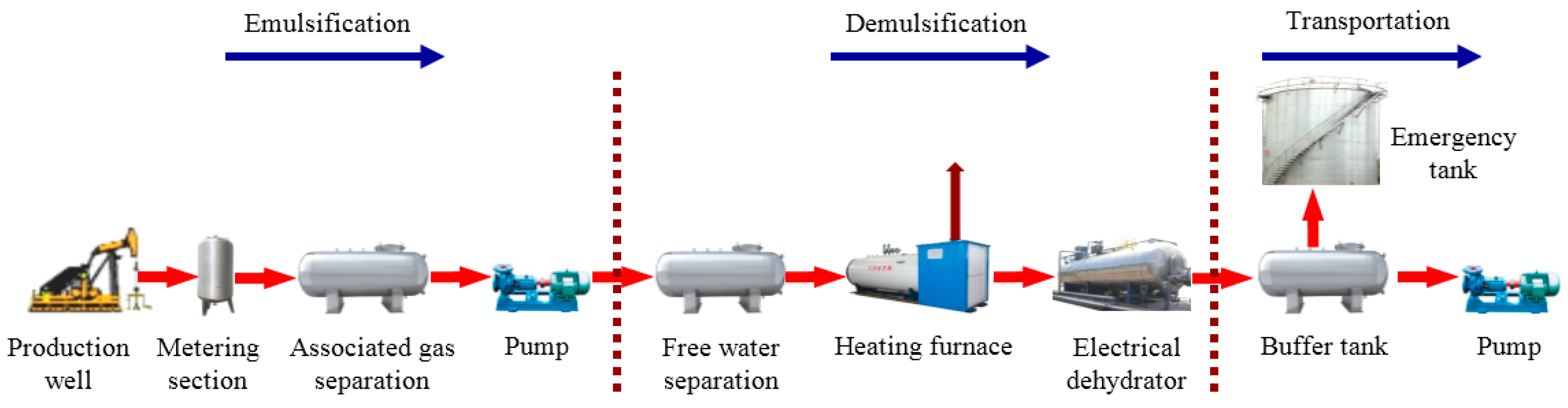
Emulsions are dispersions of two immiscible liquids whre one liquid is the dispersed phase and the other is the continuous phase. Emulsions are ubiquitous in crude oil production, and they can be classified into three broad groups: water-in-oil (W/O) emulsions, oil-in-water (O/W) emulsions, and multiple or complex emulsions [1,2]. In oil production wells, the O/W emulsion and multiple emulsion may be encountered more frequently when the water cut reaches a high value. Although the pipeline transportation capacity of viscous crudes can be effectively enhanced by creating a stable heavy oil-in-water emulsion, an intractable emulsion is responsible for oil productivity impairment, or the increase of operation cost which is associated with artificial lift and pipeline transportation, or the decrease of oil/water separation efficiency [3,4,5]. The sellable crude oil must meet a certain specification for transportation and storage on basic sediment and water (BS & W) content. However, the typical BS & W content in a large number of mature oilfields is usually far more than the specification [6]. Before the design of wet crude handling technology and facilities, it is necessary to better understand the formation and stabilization of crude oil emulsions. This may be even more important if the oil production system is to be equipped with more pumps, manifolds, valves and elbows which can create a shearing environment and result in tight emulsions. Figure 1 is a schematic illustration showing various agitation points where shearing actions take place during oil production in Daqing oilfield (China).
Emulsification of a crude oil-water system is significantly affected by conditions such as water fraction, shear intensity, and temperature [6,7]. As thermodynamically unstable systems, the stability of emulsions is determined by surface forces and intermolecular interactions [8]. Towards a thermodynamic framework to describe the emulsification mechanism, the formation of an emulsion is spontaneous if the Gibbs free energy is less than zero. However, a certain amount of energy is required to be input into the mixture to cause the desired free energy change if the Gibbs free energy is greater than zero. The existing knowledge presents that this energy requirement can be supplied by the addition of emulsifiers which can lower the interfacial tension (IFT) and promote dispersion of the droplets, thus reducing the amount of required energy to form an interface [9,10]. The emulsification behavior is activated by emulsifiers that tend to concentrate at the oil-water interface where they form interfacial films with certain strength. These films would enhance the stability of emulsion by lowering IFT and increasing the interfacial viscosity. Naturally occurring emulsifiers in the crude oil include asphaltenes, resins, organic acids and bases [11]. The previous study argued that a reduction in Zeta potential would increase the so-called attachment energy, which is the interfacial energy of emulsions [12]. As special liquid-in-liquid colloidal dispersions, emulsions can be stabilized by utilizing emulsifiers or surface active solids to remain dispersed for a period of time. However, emulsions are only kinetically stable because the interfacial Gibbs free energy change is positive, it also means that there will be a phase separation process as time goes on, and the kinetic stability is a consequence of a small droplet size, a narrow droplet-size distribution and the presence of an interfacial film around the dispersed droplets. The droplets would be more stable when the IFT decreased after emulsifiers were added, and the emulsifiers can also create a steric and electrostatic barrier to slow coalescence. The hydrodynamic interactions of droplet-droplet, droplet-particle, and particle-particle can lead to a more viscous fluid, which will slow the kinetics of coalescence [13,14]. Moreover, the higher the volume fraction of the dispersed phase is, the more viscous the emulsion is, if it is dispersed properly. The energy required to displace a solid particle from the interface is roughly 10~100 times of that required to displace an emulsifier from the same interface, so the surface active solids can also act as secondary emulsifiers at the oil-water interface to stabilize emulsions, and solid/emulsifier stabilized emulsions can have stronger stability over emulsifiers alone or solids alone [15,16]. The surface active solids detected in crude oil production include sand, clay particles, asphaltenes and waxes, mineral scales, drilling muds and corrosion products. Yang et al. argued that the adsorption of particles at interfaces may be controlled by adjusting the electrostatic interaction between particles and the interface without changing hydrophobicity, which is thought to be a main controlling factor of emulsification behavior [17]. The stabilizers suppress the mechanisms of sedimentation, aggregation, flocculation, coalescence, and phase inversion which are involved in demulsification. Additionally, the shearing action can be encountered almost in all flow fields that have velocity grades along the vertical direction of fluids flow in oil production, such as in the well-head chokes, valves, pipelines and elbows. Extreme mixing conditions are experienced as the fluid mixtures flow through these shearing fields. The well-head chokes, valves and elbows which constitute special regions of high turbulence due to the sudden reduction of flow area, and hence cause vigorous shearing action which promotes emulsion formation. New oil–water interfaces are thus formed which contributes to the formation of tight emulsions. The surface pipeline layout has been proved to be responsible for the emulsification of the crude oil with water [18]. Fluid mixtures from the production wells flow into surface flowlines and co-mingle at a manifold; these units also constitute some forms of turbulence and stabilize the emulsions in different degrees. Wen et al. argued that the emulsified water fraction of crude oil–water emulsion correlates well with entropy production rate in flowing conditions, and this correlation obeys a power law equation [19].
Furthermore, chemical flooding enhanced oil recovery (EOR) has attracted remarkable interests because of the necessity to stabilize production levels from a maturing field base [20,21,22,23]. As the biggest chemical EOR bases in the world, the oil production of chemical flooding (using polymer and alkali-surfactant-polymer) in 2016 in Daqing Oilfield approached to 88 million barrels (bbl). During the application of chemical EOR floods, breakthrough of the injection chemicals such as surfactant, alkali and polymer or polymer alone periodically occurs resulting in stable emulsions. The practice indicates that emulsions created by chemical flooding have been extremely difficult to break due to the high concentration of alkali, surfactant and polymer tightly bound with the oil and water [24]. The same as the result of strengthening shearing action, the stability of the emulsions are enhanced with an increase of chemicals concentration. The effect of production characteristics on emulsification mechanism of crude oil becomes more complicated in the EOR process. Nguyen et al. argued that polymer can enhance the emulsion stability via steric and electrostatic stabilization and can also form a “bridge” between two droplets and reduce the emulsion stability. Surfactant and alkali can contribute to the stability of dispersed droplets by decreasing the interfacial tension and Zeta potential. The main contributions for the tight emulsion were identified [25].
However, the emulsification mechanism of oilfield emulsions has always been commonly explained by discussing the interfacial Gibbs free energy change and characterizing a number of properties including appearance, droplet size and distribution, conductivities, bulk and interfacial viscosities, and BS & W, etc. In this paper, the concept of shearing energy was introduced. Basing on the mechanistic model and deformation theory of the dispersed phase droplets, the relationship between shearing stress in the flow field and IFT was established, and the correlation between shearing energy and interfacial Gibbs free energy was developed. The potential of the proposed correlation model was validated using experimental data and field data on emulsification behavior, then the role of shearing energy and interfacial Gibbs free energy in the emulsification mechanism was worked out. It was also shown that how droplet deformation could be predicted from a random deformation degree and orientation angle. The study results are contributed to improve the knowledge of waxy crude oil-water emulsions.
2. Experimental Material, Setup and Field Data
2.1. Materials and Emulsion Preparation
The conventional method of preparing simulated emulsion was replaced by sampling actual produced liquid (mixture of oil, water, and chemicals of wells). The waxy crude oil were sampled from 4 representative polymer flooding wells of the Daqing Oilfield. The physical properties of these waxy crude oil were determined according to the related standard test method [7,26]. The produced water with a salinity of 5130 mg/L and a polymer concentration of 450 mg/L were also collected and employed in the preparation of emulsions. The used ratios of produced water to crude oil after phase separation were 35:65, 55:45, 75:25, and 85:15.
A homogenizer with temperature control system was used to create emulsions by shearing, and the energetic mixing conditions can avoid cavitation and generation of air bubbles effectively. The preparation temperature of each emulsions was set as 38 °C, and the preparation amount was 1000 mL. The rotate speed of homogenizer was designed according to the equivalent shearing conditions of flow fields in oil gathering pipeline, valves and elbows:
where is the rotate speed, RPM; is the shearing velocity, s−1; and is a constant related to the structure and geometry size of homogenizer and was valued as 10.
In different shearing fields, can be determined by typical non-Newtonian rheological equation, thus 12 emulsions with different properties could be prepared.
2.2. Emulsification Property Measurements
The inversion point, at which dispersed and continuous phases in the waxy crude oil emulsion changes, was first measured in accordance with ASTM D 4440-2015 [27]. The equilibrium interfacial tension of the waxy crude oil and produced water were measured at 38 °C by dynamic interfacial tensionmeter.
An optical microscope equipped with a digital camera was used to analyze the micro-morphologies of the emulsions at 38 °C, and the emulsification behavior was characterized more intuitively.
The rheological properties of emulsions which suffered shearing action with different oil–water ratios were tested by stress controlled rheometer with the practical shear rate of 1~1000 s−1 at 38 °C. The apparent viscosities were evaluated using the rheometer with a parallel plate geometry, and the experiments were conducted in accordance with ASTM D 4440/ISO 6721-10 [28].
To further explain the emulsification behavior in different shearing fields and to draw a comparison, the droplet-size distribution was analyzed by laser particle analyzer.
2.3. Characteristic Data of Flow Field
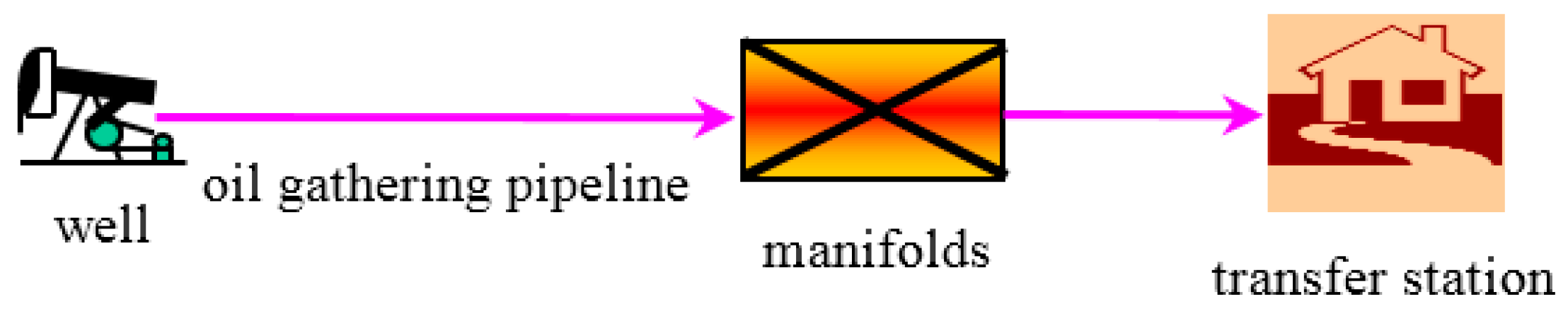
To obtain the field data and confirm the emulsification behavior of waxy crude oil in the actual shearing field. The 4 representative polymer flooding wells mentioned above were also selected from production well groups of North area in Daqing oilfield to perform model validation. The polymer injection parameters in these wells involved the relative molecular weights of 1.9 × 10⁷ Da and the concentrations of 1500 mg/L. The average water cut of the produced emulsions were 35%, 55%, 75%, and 85%, and the flow rates were 2.16 m3/h, 2.34 m3/h, 1.70 m3/h, and 1.69 m3/h respectively. The concentrations of polymer in these produced emulsions were 450 mg/L, and the producing gas-oil ratios of the wells which were lower than 20 m3/m3 were routinely determined. As shown in Figure 2, the production well connected into manifolds with horizontal single-pipe pattern, the length of oil gathering pipelines were about 180 m, and the diameters were Φ 60 × 3.5 mm (correspond to the nominal diameter of DN50). There were 2 valves (DN50) and 5 elbows (DN50) of 90° along the pipeline.
3. Mechanistic Model
The forces and deformation of dispersed droplets in flow fields have been studied for a long time, especially for the Newtonian droplets in Newtonian continuous phase, various models have been developed to predict the complex break-up behavior of droplets as well as coalescence [29,30,31,32,33]. The better understanding of dispersion mechanism has an important role in petroleum production and operation. Due to the various differences of interfacial properties and shearing action, the various models and results experienced in Newtonian fluids are not suitable to be applied to oilfield emulsion analysis directly. As a result, more efforts have been put on the research of emulsion stability and demulsification in recent years [34,35,36,37]. Most of the studies were mainly focused on the experimental work of emulsion properties and the development of correlation model, and whether their results were suitable for unsteady shearing fields was seldom mentioned. However, non-Newtonian behavior of oilfield emulsions and the differences which were probably experienced in shearing field were sufficiently considered in our work.
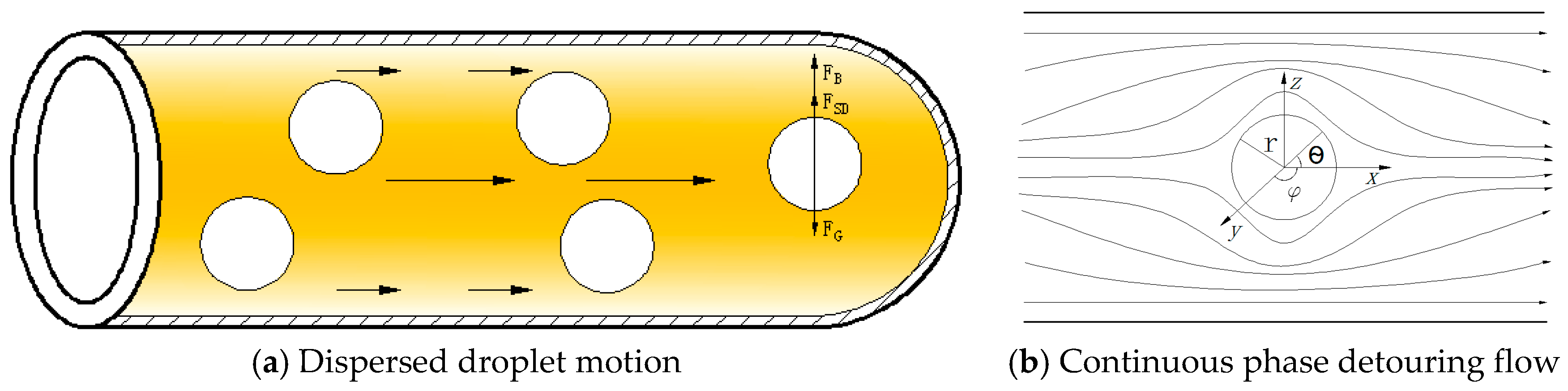
The viscosity of emulsions can be several orders of magnitude higher than the pure crude oil viscosity at normal conditions. Therefore, the inertia force of dispersed droplets can be ignored due to the domination of viscous effect to flow. As shown in Figure 3a, there are three main forces, namely, gravity, buoyancy and Stokes drag force, which control the dispersed droplet motion in the shearing field in radial direction. When the gravity is smaller than the summation of buoyancy and Stokes drag force, dispersed droplet will have an upward velocity gradient; otherwise, it will have a downward velocity gradient. The mechanistic model describes the behavior in radial direction as follows.
The gravity force and buoyancy force can be respectively calculated using the following well-known equations:
where is the gravity force, N; is the buoyancy force, N; is the density of dispersed phase, kg/m3; is the density of continuous phase, kg/m3; is the diameter of dispersed droplet, m; and is the gravitational acceleration, m/s2.
If we temporarily do not consider the deformation of spherical droplets and assume the following boundary conditions:
Using variable separation method and substitution of Equations (7)–(11) into Equations (4)–(6) gives:
where, are the coordinate parameters; are the detouring flow velocity of continuous phase in direction, m/s; is the pressure of the flow field, Pa; is the radius of dispersed droplets, m; is the relative velocity of continuous phase and dispersed phase in radial direction, m/s; and is the apparent viscosity of emulsions, Pa∙s.
Then, the surface forces on dispersed droplets can be obtained from:
where is the static pressure per unit area being perpendicular to the sphere surface and pointing to the center, Pa; and are the viscous shearing stress being tangent to the sphere surface, Pa.
Taking an area element on the sphere surface:
Integrating Equations (15) and (16) with respect to the area:
Adding a minus to Equation (20) according to the relationship of action and reaction, and the Stokes drag force can be calculated as follows:
where is the Stokes drag force, N; is the resistance caused by static pressure, N; and is the resistance caused by viscous shearing stress, N.
Furthermore, force equilibrium equation of dispersed droplets in the shearing field in the radial direction can be written as:
Ideally, the original spherical droplets will become ellipsoid in the shearing field, where the dispersed droplets commonly have moderate deformation rate. Thus the mechanistic model describing the behavior in the axial direction can also be built. As shown in Figure 4a, the radius of original spherical droplets is ; the long axis and minor axis of ellipsoids after deformation are and , respectively; and a orientation angle is activated. The deformation degree of droplets can be defined as:
Taylor has carried out researches on liquid droplet deformation and break-up in various conditions, the theory related to viscosity modeling of a fluid containing small droplets of another fluid was developed, and the probable droplet and in steady uniform shearing flow were proposed [29,39]. If comparing with viscosity force, when the deformation is dominated by IFT:
If comparing with IFT, when the deformation is dominated by viscosity force:
If viscosity force and IFT function together in the system:
The parameters could be determined by the following correlations presented by Taylor [39]:
where is the coefficient which reveals the competitive mechanism for viscosity force stretching the droplets and IFT maintaining the shape of the sphere; is the shearing stress, Pa; is IFT, N/m; is the viscosity ratio; is the viscosity of dispersed phase, Pa∙s; and is the viscosity of continuous phase, Pa∙s.
As shown in Figure 4a,b, three forces, internal pressure, viscous shearing stress and restoring force, control the deformation of hemi-ellipsoidal droplet in the shearing field.
Internal pressure:
Viscous shearing force:
Restoring force:
The static equilibrium equation of the right hemi-ellipsoidal droplets can be written as:
where is the internal pressure, N; is the viscous shearing force, N; the restoring force, N; is the deformation value of spherical droplets, m; is the droplet deformation shrinkage coefficient; and is the difference of pressure between the dispersed phase and the surrounding continuous phase, which could be determined in accordance to Laplace equation [40]:
Considering the incompressibility of fluid, droplet volume can be considered as a constant during the deformation process in the shearing field, as shown in Figure 4c, assuming the deformation value is in the -axis direction, the same deformation value, (), will be obtained in the -axis direction and -axis direction due to the axial symmetry of deformation. Thus,
Then, the droplet deformation shrinkage coefficient in the shearing field can be expressed as follow:
Furthermore, when the moderate deformation of emulsions in dispersed droplets in the shearing field is activated, it can be concluded that the droplet radius is much greater than the deformation value (). Equation (35) could be simplified and the shrinkage coefficient could be valued as:
Substituting Equations (33) and (36) into Equations (29)–(32) yields:
4. Energy Model
Clearly, the development of a novel mathematical model which is for a robust numerical simulation of the multiphase mixtures storage and transportation process in the oil and gas industry is an important issue [41]. Despite the mechanistic model having a sound theoretical basis, there are still some intrinsic limitations being shown when describing the flow behavior of emulsions and revealing the emulsification mechanism in shearing fields, it is especially inconvenient to solve due to the directivity of motion vector. Thus, a novel energy model being derived from the work done by a force is needed to fully describe the emulsion flow behavior.
The environment for the molecule on the interface between dispersed phase and continuous phase is different from that for the molecule in bulk, the resultant force on the interface is not zero and is perpendicular to the interface pointing to the interior, in other words, the fluid has a tendency to reduce the surface area if there is no extra effective work [42]. Under a certain temperature and pressure, for the emulsion with a certain property, the work consumed to extend the interface between dispersed phase and continuous phase is proportional to the increased surface area, and the proportion coefficient is equivalent to the interfacial Gibbs free energy change [43]. The interfacial Gibbs free energy change being derived from the interfacial work consumption could be expressed as Equation (38):
where is the interfacial Gibbs free energy change, J/m2; and is the surface area of extended interface, m2.
Lee used several nucleation agents in foaming experiments of foam plastic field and concluded that the product of shearing stress, shearing area and the shearing distance could be considered as the work done by the shearing action [44]. This work involved factors including melt viscosity, melt flow velocity and shearing stress. Although the melt flow velocity and shearing stress are vectors in the shearing field, the energy generated by the work is scalar. It is reasonable to connect the shearing mechanism and bubble nucleation rate in the form of energy. The higher the energy is, the greater the bubble nucleation rate is, due to the remarkable decrease of free energy barrier for bubble nucleation.
where is the work for shearing, J; is the shearing stress related to viscosity and velocity, Pa; is the shearing area, m2; and is the shearing distance, m.
Furthermore, the energy generated from the work done by the shearing action, shearing energy, is responsible for dispersion of one phase of the oil-water system into the other as the system flows in the shearing field [45]. As shown in Figure 5, taking oil-water system with known properties flowing in a circular pipeline with known internal surface area and length as an example, shearing energy is a function of the pressure drop along the specific shearing field, however, the amount of energy depends on the turbulence available in the flow field. If we assume the shearing energy in the specific flow field is isotropic and the role in all directions is the same, then:
where is the shearing energy in the specific shearing field, J; and is the flow pressure drop, Pa.
It can be noted that the pressure drop can be readily determined if relative data, which is about the emulsion properties, necessary flow parameters, geometrical parameters of flow field, the sudden increase or reduction of flow area and the surface roughness of flow regions, is available. Moreover, the shearing energy in the unit , which indicates the shearing force per unit area and per unit distance of the region exposed to the flow can also be solved.
Substituting Equation (37) into Equation (39) gives the model of the work done by shearing action for waxy crude oil–water emulsion flow, which could be used to reveal the generated shearing energy as:
Combining Equations (38) and (41), we could get the correlation model between shearing energy and interfacial Gibbs free energy change:
Deformation degree if comparing with the viscosity force, when the deformation is dominated by IFT. From Equation (23) and Figure 4a,c, it is clear that the deformation value , and the orientation angle . However, the critical deformation degree will be generated if comparing with IFT, when the deformation is dominated by viscosity force, then the deformation value , and the orientation angle . Thus, two simplified limit state equations could be written as follows:
It is clear that the orientation angle of dispersed droplet , where the maximum value and the minimum value of interfacial Gibbs free energy change could be presented in the format above. The maximum value is equivalent to the Gibbs free energy needed to be overcame to start the extension of the original interface of oil–water emulsion, and the minimum value is equivalent to the Gibbs free energy needed to be overcame after the realization of the maximum extension for the interface of oil–water emulsion.
5. Results and Discussion
5.1. Properties of the Waxy Crude Oil
The physical properties of the waxy crude oil specimens which were produced from four representative polymer flooding wells were measured and determined. The average wax content and freezing point of the experimental crude oil were measured as 26.2% and 35.6 °C, respectively. The average density of waxy crude oil was 0.8522 g/cm3. The average viscosity of waxy crude oil was 32.1 mPa·s at 40 °C. The average resins and asphaltenes were determined as 6.8% and 3.7%, respectively.
5.2. Phase Inversion and Emulsification Behavior of the Waxy Crude Oil Emulsions
As shown in Figure 6, the phase inversion property test results indicated that the apparent viscosity of the waxy crude oil emulsions changed significantly when the water cut was at around 60%. It means that water droplets would disperse in oil under low fraction of water, and water droplets would further concentrate with the increase of water fraction. However, water droplets began coalescing entrapping the oil into droplets when the water cut was at around 60%. With the further increase of water fraction, there would be larger droplets being formed until they became the continuous phase, and the apparent viscosity of the waxy crude oil emulsion dropt sharply. The phase inversion point, where the type of the waxy crude oil emulsion changed from one to another, was determined as 60% under different operating conditions at 38 °C. The investigation made by Ersoy and Sarica showed that estimation of the phase inversion point was important to improve the emulsion viscosity correlations [46], and this was confirmed in our experiments. In addition to being useful for making waxy crude oil emulsion viscosity prediction, understanding of phase inversion behavior is important to explain the emulsification mechanism based on the energy analysis.
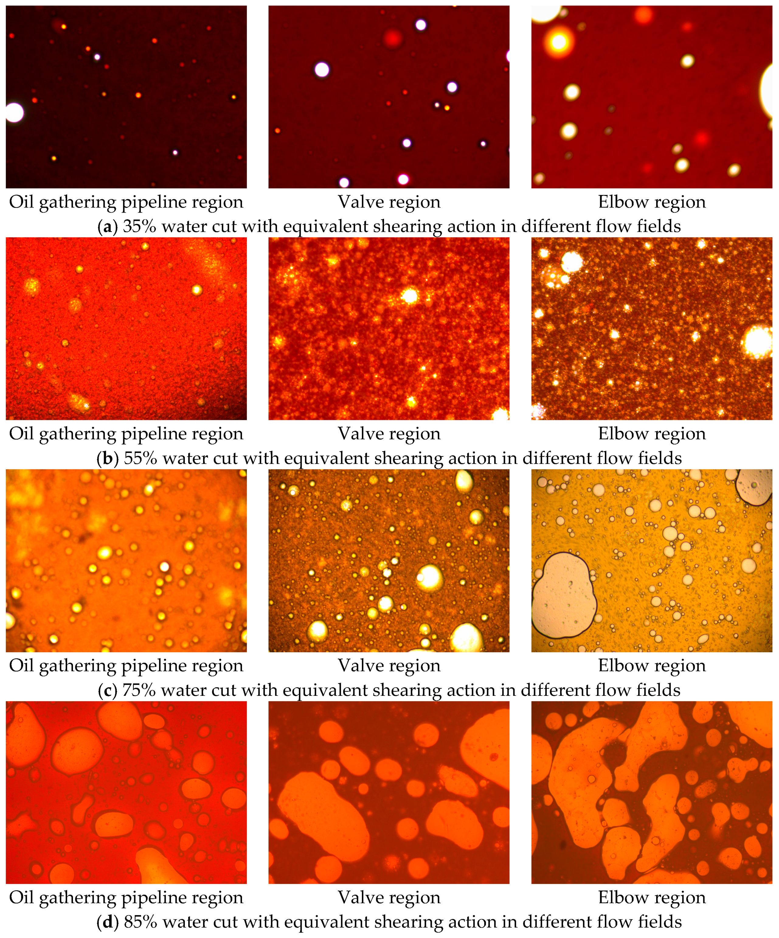
Figure 7 shows the various emulsification structures of the waxy crude oil emulsions under the same magnification (10 × 20) of microscope. It indicated that one of the most important factor for emulsion structure was the fraction of water, and the multiple emulsions (W/O/W) were observed when it reached a higher water fraction. The reason for this is that the water fraction contributes to keeping the droplets in their original shape and distribution when the containing polymer in produced water tries to bound the droplets. When scaling the emulsion structure, for example, the formation of tight emulsions is at the phase inversion temperature [6,46]. This is in agreement with the significant increase of emulsion viscosity which is close to the water cut where dispersed droplets begin coalescing entrapping the continuous phase into dispersed droplets. Another important factor is the shearing action, which indicates that the droplet deformation should not be ignored. The emulsions which experienced the shearing which is equivalent to that in the flow field of elbow regions have better dispersity, the irregular degree of dispersed droplets is enhanced and the rigid interfacial films emerge. It revealed that the sudden change of flow area is responsible for the fact that both droplet deformation and some components (i.e., waxes and asphaltenes) of the crude oil contribute to the emulsion stability and tightness.
5.3. Interfacial and Rheological Properties of the Waxy Crude Oil Emulsions
The equilibrium interfacial tension of the waxy crude oil and produced water were measured as 23.6 mN/m (38 °C). It can be concluded that there were not much surface active substances adsorbed on the surface of dispersed droplets in the emulsions and the interfacial activity would not be enhanced significantly when the polymer appeared in the produced water. The shearing energy and interfacial Gibbs free energy in emulsification behavior can be correlated with the measurable interfacial tension.
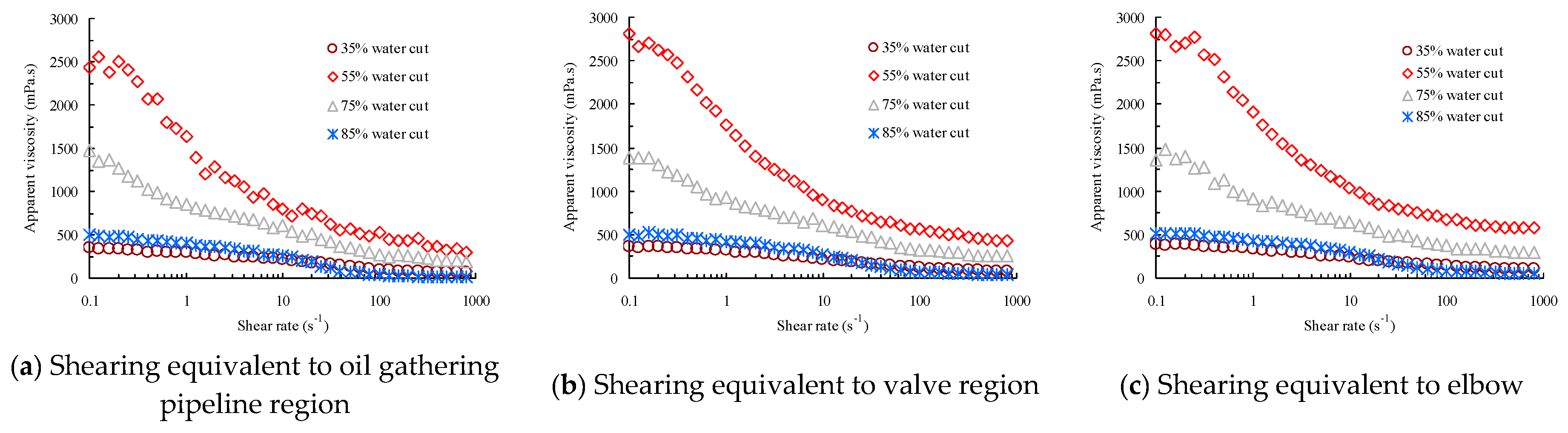
In Figure 8, we can see that the viscosities of emulsions were substantially higher than the viscosity of either the waxy crude oil or the produced water and the emulsions behaved as shear-thinning fluids, which indicated that the non-Newtonian behavior could be caused by droplet “crowding” or structural viscosity of the emulsions. When the water cut was above 35%, the slopes of the rheology curves obviously deviated from zero, pseudoplastic characteristics of the waxy crude oil emulsions would be exhibited. It is clear that the highest viscosities were achieved as the fraction of water increased up to 55%, which indicated the phase inversion behavior could appear after entering the water containing stage. Moreover, the higher viscosities and anti-shear ability of the emulsions which were created with strong shearing action were shown. In addition, the fluctuant apparent viscosity readings tended to be stable, and the systems could be called as “medium emulsions” or “tight emulsions” instead of “loose emulsions”. The properties are in agreement with the knowledge of phase inversion and emulsification behavior of the waxy crude oil emulsions and are also available for solving both mechanistic and energy models.
5.4. Droplet Size and Droplet-Size Distribution of the Waxy Crude Oil Emulsions
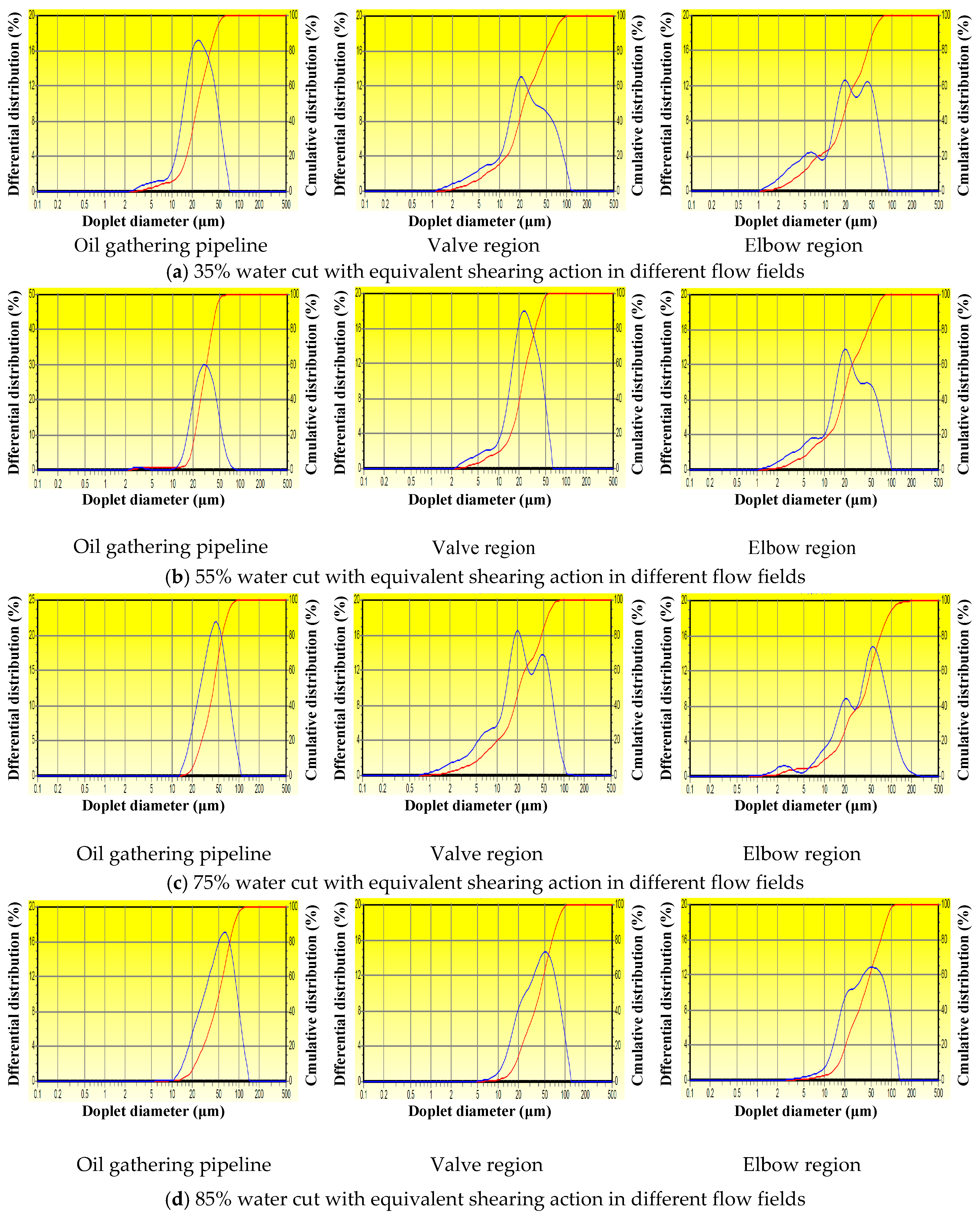
The droplet-size distributions of typical emulsions in different shearing patterns are shown in Figure 9. It indicated that the droplet diameters of emulsions concentrated at 0.5~80 μm, the distribution range would be wider when the emulsion changed into the type with water being the continuous phase. The droplets of the dispersed phase also began to coalesce to form larger droplets until the dispersed phase became the continuous phase, and the mean diameter was larger than 50 μm when the water fraction was over 75% according to the experimental results. Moreover, the suffered shearing in a certain degree had some effect on droplet-size. Although the droplet diameters may present abnormal distribution in the elbow region, which is a shearing field that have sudden change characteristic of flow area, the mean diameters of droplets in this region still decrease. This revealed a natural tendency for the enhance of emulsion stability and tightness in the turbulent shearing field. This is also in agreement with the structure of the waxy crude oil emulsions observed as above (Figure 7). In the simulation of the shearing which was equivalent to oil gathering pipeline region, valve region, and elbow region, the mean droplet diameters in the emulsion with 35% water cut were 30.42 μm, 29.01 μm, and 27.35 μm; those in the emulsion with 55% water cut were 25.57 μm, 23.46 μm, and 21.08 μm; those in the emulsion with 75% water cut were 48.47 μm, 45.41 μm, and 42.43 μm; and those in the emulsion with 85% water cut were 54.96 μm, 50.30 μm, and 46.29 μm, respectively. The results also provided critical data for deformation characteristic parameter determination of dispersed droplets in different flow regions.
5.5. Shearing Energy and Interfacial GIBBS Free Energy Change in the Actual Flow Field
As mentioned previously, the water cut varies from 35% to 85% for the produced emulsions in the actual flow field. From Equations (23), (26) and (37), basing on the experimental results and field data, the deformation characteristic parameters of dispersed droplets can be determined in Table 1. It is clear that the multiple increase of deformation value and orientation angle is shown when the produced emulsion with the same water fraction enters the valve region and elbow region. Especially, and of the dispersed droplet in elbow region could be 300% and 200% more than those in oil gathering pipeline region with the same water cut respectively. The orientation angle of the dispersed droplets increases when water fraction of the produced emulsions is close to phase inversion point in any flow region, which further revealed that the waxy crude oil–water emulsion is a thermodynamic unstable system. The same as the characteristic of orientation angle , the deformation degree of the dispersed droplets also increases at the point of phase inversion and in the elbow region where suffers strong shearing action if the original droplet-size of the waxy crude oil emulsions is considered.
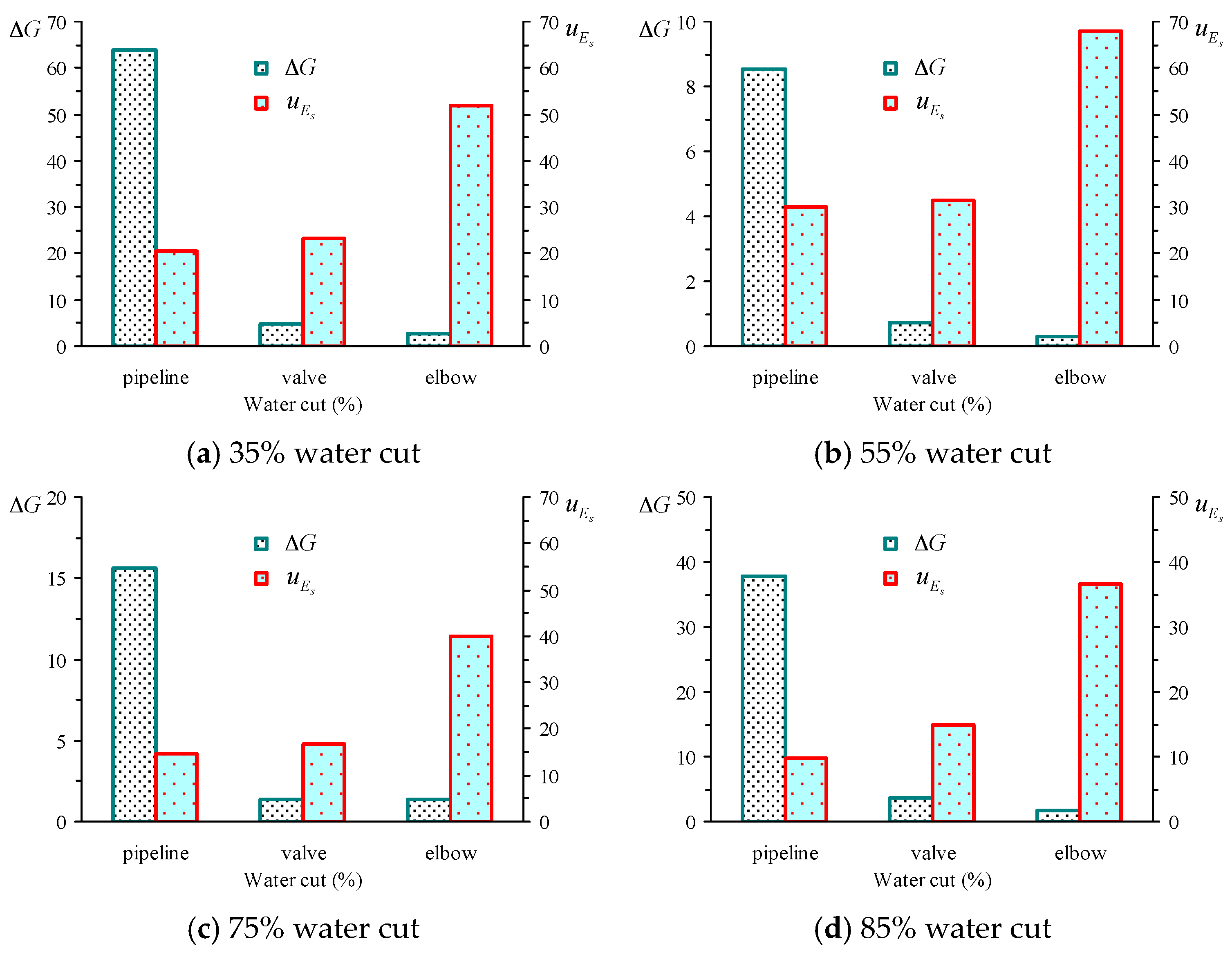
We use the correlation model to identify the effect level of interfacial performance and shearing action on the emulsification mechanism of waxy crude oil. As shown in Figure 10 and Figure 11, the interfacial Gibbs free energy change and shearing energy in the unit for these emulsions in different shearing field were calculated, and the results showed that the shearing energy of the emulsion with 55% water cut in any shearing field was the highest, and the shearing energy of the emulsion with any water cut in the elbow region was the highest. Notice that the value of interfacial Gibbs free energy change was opposite under these conditions, which means that the system needs to further overcome the least interfacial Gibbs free energy. Thus, it can be concluded that the shearing energy contributes to the reduction of interfacial Gibbs free energy for oil–water emulsification. The reason for this is that, according to the energy conservation equation, the total energy of any system is the sum of the internal energy and kinetic energy, different from the static environment, the kinetic energy is generated when the oil-water mixture is in the flow field. However, the shearing energy, as the energy generated by the work done by the shearing action, becomes a form of energy for overcoming the oil-water interfacial Gibbs free energy for emulsification. Thus, the shearing energy is an effective form which can show the contribution of the kinetic energy of the oil-water mixture to interfacial Gibbs free energy in the process of emulsification, and the role of shearing energy and interfacial Gibbs free energy in the emulsification mechanism of waxy crude oil were quantified and explained using the models. This finding in this study is also in agreement with the previous understanding that shearing energy was responsible for the dispersion of one phase of the liquid into the other as the fluid flows through the pipeline and it depended on the turbulence available in the pipeline, which was emphasized by Abdel-Aal et al. There is potential of using the correlation model of shearing energy and interfacial Gibbs free energy to describe the emulsification behavior of oil–water mixture in the shearing field.
6. Conclusions
The mechanistic model of dispersed droplets which was considered in the radial direction and axis direction in waxy crude oil emulsions has been developed to correlate the shearing stress and IFT. The concept of shearing energy has been introduced to reveal the driving force for emulsification, and a novel correlation model of the shearing energy and interfacial Gibbs free energy has also been developed. A validation of the proposed model, performed by correlating the experimental data and field data which was from the actual flow field, has been carried out.
The deformation degree and orientation angle of the dispersed droplet will increase at the point of phase inversion and in the strong shearing field according to the prediction of this model which used the experimental results. In any shearing field, the shearing energy was the highest when the dispersed phase and continuous phase of emulsions was close to the inversion point, and interfacial Gibbs free energy change was always the lowest. In addition, the shearing energy of the emulsions with any water cut in special regions with sudden change of flow field was the highest and the interfacial Gibbs free energy change was the lowest. The results revealed that the shearing energy is an effective form which can show the contribution of the kinetic energy of the oil–water mixtures to interfacial Gibbs free energy in the process of emulsification.
Considering that emulsions can be encountered in almost all phases of the crude oil production and processing and that the understanding of the emulsification behavior and mechanism during oilfield production still remains a very challenging scientific problem for both engineers and operators, the correlation model of shearing energy and interfacial Gibbs free energy which was developed in this study has potential for describing the emulsification behavior of the oil–water mixture in the shearing field.
Acknowledgments
This work was financially supported by the National Natural Science Funds for Young Scholars of China (Grant No. 51404068), the China Postdoctoral Science Foundation (Grant No. 2017M611349) and the Postdoctoral Science Foundation of Heilongjiang Province in China (Grant No. LBH-Z16037), and the University Nursing Program for Young Scholars with Creative Talents in Heilongjiang Province of China (Grant No. UNPYSCT-2015074), which are gratefully acknowledged.
Author Contributions
Zhihua Wang performed all the modeling and prepared the manuscript. Xinyu Lin prepared the samples and performed the experiments. Mengmeng Xu and Shuyi Zhan collected the field data and discussed the results. Zhenhua Rui assisted for experimental design and revised the manuscript. The whole work was supervised by Zhihua Wang.
Conflicts of Interest
The authors declare no conflict of interest.
References
- Schubert, H.; Armbroster, H. Principles of formation and stability of emulsions. Chem. Ing. Tech. 1989, 61, 701–711. [Google Scholar] [CrossRef]
- Visintin, R.F.G.; Lockhart, T.P.; Lapasin, R.; D’Antona, P. Structure of waxy crude oil emulsion gels. J. Non Newton. Fluid Mech. 2008, 149, 34–39. [Google Scholar] [CrossRef]
- Zheng, S.; Fogler, H.S. Fundamental investigation of wax diffusion characteristics in water-in-oil emulsion. Ind. Eng. Chem. Res. 2015, 54, 4420–4428. [Google Scholar] [CrossRef]
- Li, S.; Huang, Q.; He, M.; Wang, W. Effect of water fraction on rheological properties of waxy crude oil emulsions. J. Dispers. Sci. Technol. 2014, 35, 1114–1125. [Google Scholar] [CrossRef]
- Rui, Z.; Metz, P.A.; Reynolds, D.B.; Chen, G.; Zhou, X. Regression models estimate pipeline construction costs. Oil Gas J. 2011, 109, 120–127. [Google Scholar]
- Wen, J.; Zhang, J.; Wang, Z.; Zhang, Z.; Zheng, F.; Zhu, Y.; Han, S. Full and partial emulsification of crude-systems as a function of shear intensity, water fraction, and temperature. Ind. Eng. Chem. Res. 2014, 53, 9513–9520. [Google Scholar] [CrossRef]
- Shinoda, K.; Saito, H. The effect of temperature on the phase equilibria and the types of dispersions of the ternary system composed of water, cyclohexane, and nonionic surfactant. J. Colloid Interface Sci. 1968, 26, 70–74. [Google Scholar] [CrossRef]
- Tambe, D.E.; Sharma, M.M. Factors controlling the stability of colloid-stabilized emulsions I. An experimental investigation. J. Colloid Interface Sci. 1993, 157, 244–253. [Google Scholar] [CrossRef]
- Mann, J.A. A free energy model for curved surfaces and curved thin films in emulsions. J. Dispers. Sci. Technol. 2002, 23, 199–207. [Google Scholar] [CrossRef]
- Li, X.; Kersten, S.R.A.; Schuur, B. Efficiency and mechanism of demulsification of oil-in-water emulsions using ionic liquids. Energy Fuels 2016, 30, 7622–7628. [Google Scholar] [CrossRef]
- Tavakkoli, M.; Chen, A.; Sung, C.; Kidder, K.M.; Lee, J.J.; Alhassan, S.M.; Vargas, F.M. Effect of emulsified water on asphaltene instability in crude oils. Energy Fuels 2016, 30, 3676–3686. [Google Scholar] [CrossRef]
- Binks, B.P.; Fletcher, P.D.I.; Petsev, D.N.; Cho, W.G. Stability of oil-in-water emulsions in a low interfacial tension system. Langmuir 2000, 16, 1025–1034. [Google Scholar] [CrossRef]
- Angle, C.W.; Hamza, H.A.; Dabros, T. Size distributions and stability of toluene diluted heavy oil emulsions. Am. Inst. Chem. Eng. 2006, 52, 1257–1266. [Google Scholar] [CrossRef]
- Pal, R. Shear viscosity behavior of emulsions of two immiscible liquids. J. Colloid Interface Sci. 2000, 225, 359–366. [Google Scholar] [CrossRef] [PubMed]
- Berger, P.D.; Hsu, C.; Arendell, J.P. Designing and selecting demulsifiers for optimum field performance on the basis of production fluid characteristics. SPE Prod. Eng. 1988, 3, 522–526. [Google Scholar] [CrossRef]
- Kazuhiro, K.; Paschalis, A. Effect of surfactant phase behavior on emulsification. J. Colloid Interface Sci. 2016, 466, 138–149. [Google Scholar]
- Yang, F.; Niu, Q.; Lan, Q.; Sun, D. Effect of dispersion pH on the formation and stability of Pickering emulsions stabilized by layered double hydroxides particles. J. Colloid Interface Sci. 2007, 306, 285–295. [Google Scholar] [CrossRef] [PubMed]
- Wang, Z.; Liu, Y.; Li, J.; Zhuge, X.; Zhang, L. Study on two-phase oil-water gelling deposition behavior in low-temperature transportation. Energy Fuels 2016, 30, 4570–4582. [Google Scholar] [CrossRef]
- Wen, J.; Zhang, J.; Wei, M. Effective viscosity prediction of crude oil-water mixtures with high water fraction. J. Pet. Sci. Eng. 2016, 147, 760–770. [Google Scholar] [CrossRef]
- Alvarado, V.; Wang, X.; Moradi, M. Stability proxies for water-in-oil emulsions and implications in aqueous-based enhanced oil recovery. Energies 2011, 4, 1058–1086. [Google Scholar] [CrossRef]
- Yuan, B.; Su, Y.; Moghanloo, R.G.; Rui, Z.; Wang, W.; Shang, Y. A new analytical multi-linear solution for gas flow toward fractured horizontal well with different fracture intensity. J. Nat. Gas Sci. Eng. 2015, 23, 227–238. [Google Scholar] [CrossRef]
- Zhang, R.; Yin, X.; Winterfeld, P.H.; Wu, Y.S. A fully coupled thermal-hydrological-mechanical-chemical model for CO2 geological sequestration. J. Nat. Gas Sci. Eng. 2016, 28, 280–304. [Google Scholar] [CrossRef]
- Zhang, R.; Yin, X.; Wu, Y.S.; Winterfeld, P.H. A fully coupled model of nonisothermal multiphase flow, solute transport and reactive chemistry in porous media. Proccedings of the SPE Annual Technical Conference and Exhibition, SPE 159380, San Antonio, TX, USA, 8–10 October 2012. [Google Scholar]
- Nguyen, D.; Sadeghi, N.; Houston, C. Emulsion characteristics and novel demulsifiers for treating chemical EOR induced emulsions. Proccedings of the SPE Enhanced Oil Recovery Conference, SPE 143987, Kuala Lumpur, Malaysia, 19–21 July 2011. [Google Scholar]
- Nguyen, D.; Sadeghi, N. Stable emulsion and demulsification in chemical EOR flooding: Challenges and best practices. Proccedings of the SPE EOR Conference at Oil and Gas West Asia, SPE 154044, Muscat, Oman, 16–18 April, 2012. [Google Scholar]
- Wen, J.; Zhang, J.; Wang, Z.; Zhang, Y. Correlations between emulsification behaviors of crude oil-water systems and crude oil compositions. J. Pet. Sci. Eng. 2016, 146, 1–9. [Google Scholar] [CrossRef]
- Standard Test Method for Plastics: Dynamic Mechanical Properties melt Rheology; ASTM D4440-2015; American Society for Testing and Materials: West Conshohocken, PA, USA, 2015.
- Plastics: Determination of Dynamic Mechanical Properties Part 10: Complex Shear Viscosity Using a Parallel-Plate Oscillatory Rheometer; ISO 6721-10-1999; International Organization for Standardization: Geneva, Switzerland, 1999.
- Taylor, G.I. The formation of emulsions in definable fields of flow. Proc. R. Soc. A Math. Phys. Eng. Sci. 1934, 146, 501–523. [Google Scholar] [CrossRef]
- Cox, R.G. The deformation of a drop in a general time-dependent fluid flow. J. Fluid Mech. 1969, 37, 601–623. [Google Scholar] [CrossRef]
- Barthès-Biesela, D.; Acrivosa, A. Deformation and burst of a liquid droplet freely suspended in a linear shear field. J. Fluid Mech. 1973, 61, 1–22. [Google Scholar] [CrossRef]
- Bentley, B.J.; Leal, L.G. An experimental investigation of drop deformation and breakup in steady, two-dimensional linear flows. J. Fluid Mech. 1986, 167, 241–283. [Google Scholar] [CrossRef]
- Levitt, L.; Macosko, C.W.; Pearson, S.D. Influence of normal stress difference on polymer drop deformation. Polym. Eng. Sci. 1996, 36, 1647–1655. [Google Scholar] [CrossRef]
- Kokal, S. Crude-oil emulsions: A state-of-the-art review. SPE Prod. Facil. 2005, 20, 5–13. [Google Scholar] [CrossRef]
- Wang, Z.; Le, X.; Feng, Y.; Hu, Z. Dehydration of aging oil by an electrochemical method. Chem. Technol. Fuels Oils 2014, 50, 262–268. [Google Scholar] [CrossRef]
- Hart, A. A review of technologies for transporting heavy crude oil and bitumen via pipelines. J. Pet. Explor. Prod. Technol. 2014, 4, 327–336. [Google Scholar] [CrossRef]
- Zolfaghari, R.; Fakhru’l-Razi, A.; Abdullah, L.C.; Elnashaie, S.S.E.H.; Pendashteh, A. Demulsification techniques of water-in-oil and oil-in-water emulsions in petroleum industry. Sep. Purif. Technol. 2016, 170, 377–407. [Google Scholar] [CrossRef]
- Kholodenko, A.L.; Douglas, J.F. Generalized Stokes-Einstein equation for spherical particle suspensions. Phys. Rev. E 1994, 51, 1081–1090. [Google Scholar] [CrossRef]
- Taylor, G.I. The viscosity of a fluid containing small drops of another fluid. Proc. R. Soc. A Math. Phys. Eng. Sci. 1932, 138, 41–48. [Google Scholar] [CrossRef]
- Clausse, D.; Pezron, I.; Gauthier, A. Water transfer in mixed water-in-oil emulsions studied by differential scanning calorimetry. Fluid Phase Equilibria 1995, 110, 137–150. [Google Scholar] [CrossRef]
- D’Alessandro, V.; Giacchetta, G.; Leporini, M.; Marchetti, B.; Terenzi, A. Modelling blowdown of pressure vessels containing two-phase hydrocarbons mixtures with the partial phase equilibrium approach. Chem. Eng. Sci. 2015, 126, 719–729. [Google Scholar] [CrossRef]
- Ruckenstein, E.; Ebert, G.; Platz, G. Phase behavior and stability of concentrated emulsions. J. Colloid Interface Sci. 1989, 133, 432–441. [Google Scholar] [CrossRef]
- Ghosh, L.; Das, K.P.; Chattoraj, D.K. Thermodynamics of adsorption of inorganic electrolytes at air/water and oil/water interfaces. J. Colloid Interface Sci. 1988, 121, 278–288. [Google Scholar] [CrossRef]
- Lee, S.T. Shear effects on thermoplastic foam nucleation. Polym. Eng. Sci. 1993, 33, 418–422. [Google Scholar] [CrossRef]
- Opawale, A.; Osisanya, S.; Dulu, A.; Otakoro, S. An integrated approach to selecting and optimizing demulsifier chemical injection points using shearing energy analysis: A justification for downhole injection in high pressured well. Proccedings of the Offshore Technology Conference, OTC 21151, Houston, TX, USA, 2–5 May, 2011. [Google Scholar]
- Ersoy, G.; Sarica, C. Modeling of inversion point for heavy oil-water emulsion systems. SPE Proj. Facil. Constr. 2009, 4, 47–52. [Google Scholar] [CrossRef]
Figure 1.
Illustration of the sources of agitation during oil production.

Figure 2.
Illustration of oil gathering process.

Figure 3.
Schematic of forces on dispersed droplets in shearing fields.

Figure 4.
Schematic of dispersed droplet deformation in shearing field.
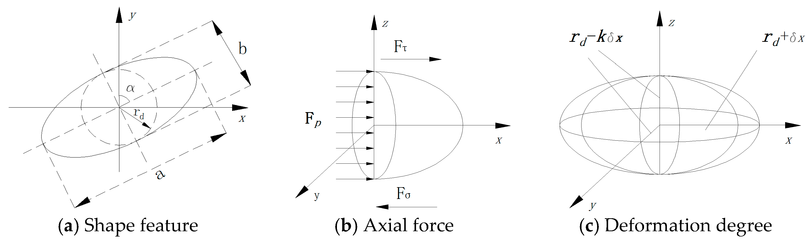
Figure 5.
Description of the experienced shearing energy of emulsions flowing in a shearing field.
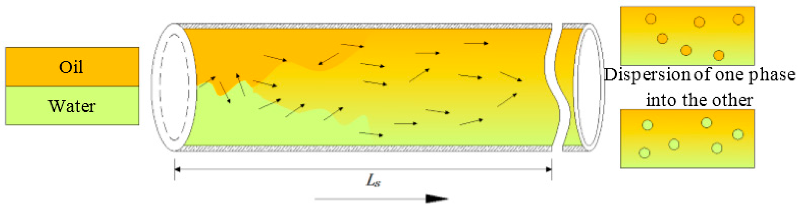
Figure 6.
Phase inversion process of the waxy crude oil emulsions.
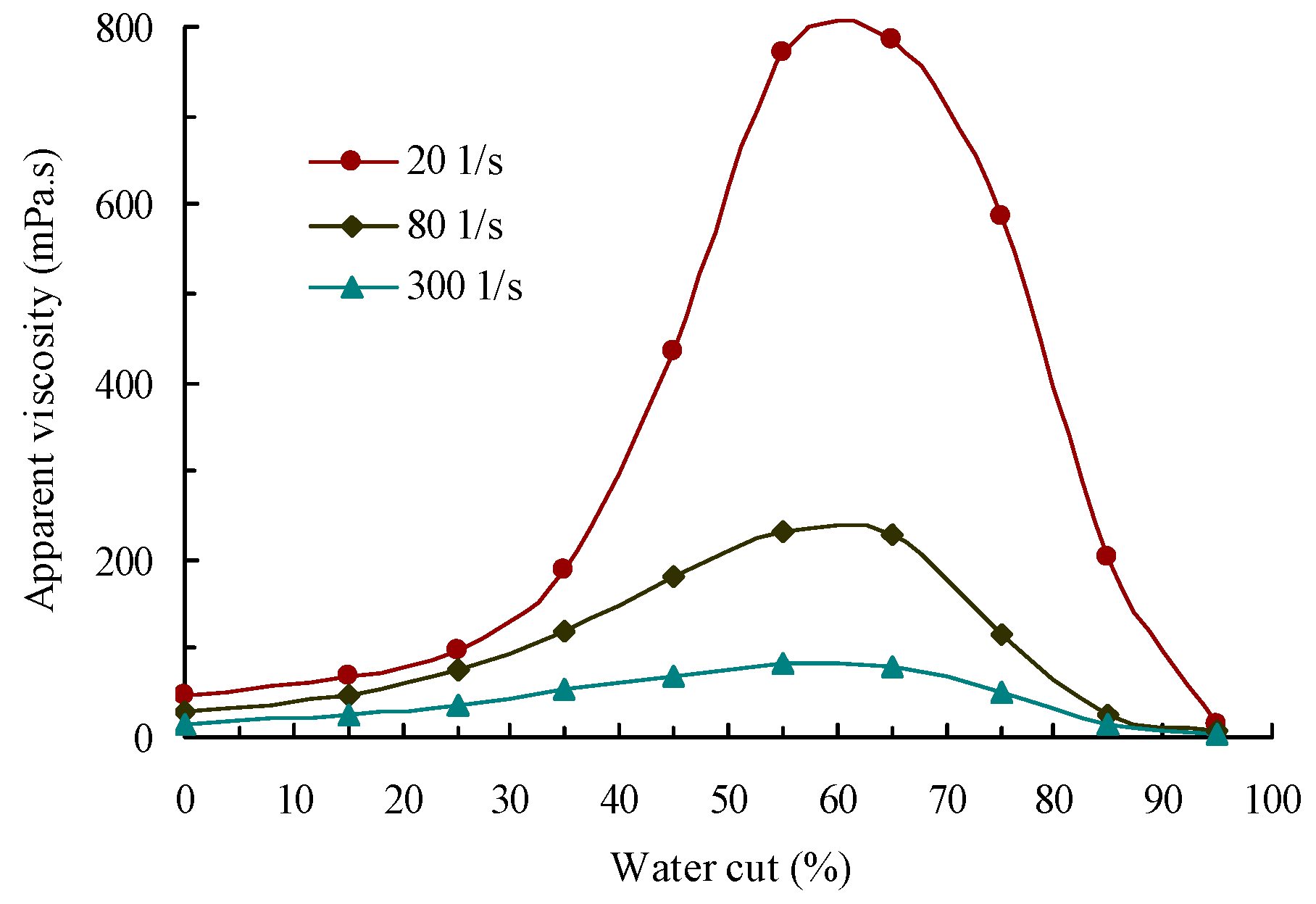
Figure 7.
Photomicrographs of the waxy crude oil emulsions.

Figure 8.
The viscosities of waxy crude oil emulsions as a function of shearing rate.

Figure 9.
Droplet-size distribution of the waxy crude oil emulsions.

Figure 10.
Effect of water cut on shearing energy and interfacial Gibbs free energy change.
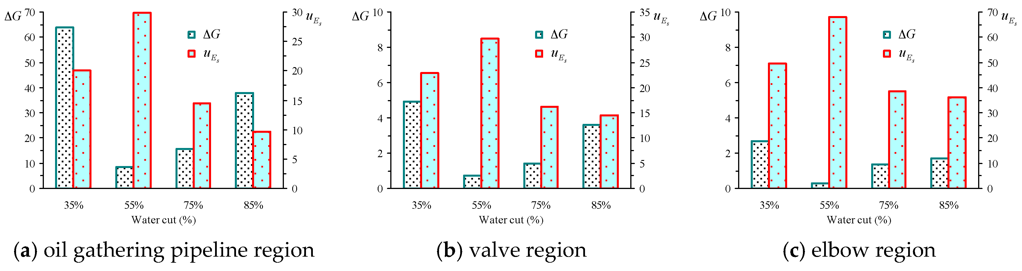
Figure 11.
Effect of flow region on shearing energy and interfacial Gibbs free energy change.

Table 1.
Deformation characteristic parameters of dispersed droplet in different flow region.
| Water Cut | Oil Gathering Pipeline Region | Valves Region | Elbow Region | |||
|---|---|---|---|---|---|---|
| (μm) | (rad) | (μm) | (rad) | (μm) | (rad) | |
| 35 | 1.442 | 0.2505 | 3.874 | 0.342 | 6.430 | 0.368 |
| 55 | 1.268 | 0.2536 | 3.512 | 0.406 | 5.346 | 0.459 |
| 75 | 2.287 | 0.2530 | 5.903 | 0.392 | 8.712 | 0.441 |
| 85 | 2.439 | 0.2508 | 6.510 | 0.345 | 10.488 | 0.394 |
© 2017 by the authors. Licensee MDPI, Basel, Switzerland. This article is an open access article distributed under the terms and conditions of the Creative Commons Attribution (CC BY) license (http://creativecommons.org/licenses/by/4.0/).
Share and Cite
MDPI and ACS Style
Wang, Z.; Lin, X.; Rui, Z.; Xu, M.; Zhan, S. The Role of Shearing Energy and Interfacial Gibbs Free Energy in the Emulsification Mechanism of Waxy Crude Oil. Energies 2017, 10, 721. https://doi.org/10.3390/en10050721
AMA Style
Wang Z, Lin X, Rui Z, Xu M, Zhan S. The Role of Shearing Energy and Interfacial Gibbs Free Energy in the Emulsification Mechanism of Waxy Crude Oil. Energies. 2017; 10(5):721. https://doi.org/10.3390/en10050721
Chicago/Turabian StyleWang, Zhihua, Xinyu Lin, Zhenhua Rui, Mengmeng Xu, and Shuyi Zhan. 2017. "The Role of Shearing Energy and Interfacial Gibbs Free Energy in the Emulsification Mechanism of Waxy Crude Oil" Energies 10, no. 5: 721. https://doi.org/10.3390/en10050721
Note that from the first issue of 2016, this journal uses article numbers instead of page numbers. See further details here.