
Analysis of Development Pattern of a Water-Flowing Fissure Zone in Shortwall Block Mining


1
School of Mines, China University of Mining & Technology, Xuzhou 221116, China
2
Key Laboratory of Deep Coal Resources Mining, Ministry of Education of China, Xuzhou 221116, China
*
Author to whom correspondence should be addressed.
Energies 2017, 10(5), 734; https://doi.org/10.3390/en10050734
Submission received: 19 April 2017
/
Revised: 8 May 2017
/
Accepted: 17 May 2017
/
Published: 20 May 2017
Abstract
:In order to effectively recover the residual coal resources, such as coal pillars and irregular coal blocks induced by large-scale extensive mining, in this study, we proposed a shortwall block mining (SBM) technology and examined the development pattern of the water-flowing fissure zone (WFZ) in the overlying strata during the SBM process. By analyzing the overlying rocks’ movement rules in SBM, the main controlling factors affecting the development of the height of the water-flowing fissure zone (HWFZ) determined are as follows: mining height, block length, and the width of the protective coal pillar among the blocks. Moreover, based on the elastic foundation beam theory, the mechanical model for the calculation of HWFZ in SBM was established. Based on the first strength theory, the calculation formula of the development HWFZ was derived. Using this model, the calculated HWFZ after SBM was 50.3 m, whereas the measured heights of the leakage of drilling washing fluid were 47.98 and 50.06 m, respectively. The calculated values almost fit well with the field-measured data, verifying the reliability of the proposed mechanical model. The results of this study can provide a significant reference for enhancing the recovery ratio of coal resources and optimizing water protection mining theory.
1. Introduction
Due to large-scale extensive mining and informal mining arrangements, a vast amount of residual coal resources, such as coal pillars and irregular coal bodies, have piled up after longwall mining for a long time [1,2,3]. To maximize the coals’ recovery ratio and the mine’s service period, in this study, we proposed a shortwall block mining (SBM) technology to recover the residual coal resources. Compared to the traditional shortwall mining technology, SBM can integrate excavation and enhance the recovery ratio of coal pillars and the mining efficiency in the working face [3,4], and has already become a main technique for the recovery of residual coal pillars. However, the recovery would inevitably cause the movement and destruction of the overlying rocks and form the water-flowing fissure zone (WFZ) [5], when the fissures develop aquifers and water-bearing regions on the surface, resulting in a loss of a great amount of water, thus depleting the water resource and affecting ecological environment. These adverse effects are particularly serious in the mines in the arid and semi-arid Western China [6,7,8,9,10,11,12,13]. Therefore, the evolution rule of WFZ of the overlaying strata during the block mining is an important technical problem that needs to be urgently addressed.
SBM technology has been investigated in detail, attaining significant achievements by researchers across the globe. Zhou et al. [3,14] focused on the stress condition on coal pillars and the movement of roof and systematically analyzed the variation rules of mine pressure during SBM; Cao et al. [4] examined the catastrophic instability mechanisms of the protection coal pillars among blocks during SBM from the perspective of cusp catastrophe theory. However, the development rules of WFZ during SBM process have not been investigated in detail and need further exploration. The arrangement of working face shows a significant difference between SBM and longwall mining, and the effect of multiple factors including the mining height and block length, the width of protection coal pillars among the blocks, and the mining depth on height of the water-flowing fissure zone (HWFZ) was investigated. The empirical formulas for The Regulation of Ming Hydrogeology (hereinafter referred to as The Regulation) are not applicable under practical conditions.
According to the characteristics of SBM technology, the main controlling factors affecting HWFZ were investigated in detail. Based on the destruction characteristics of the overlying strata, the mechanical model of the superposed beam on the elastic foundation for describing the overlying strata movements in SBM stope was established. In addition, the development rules of WFZ during the SBM process were established and finally industrially verified by the field measured data. This study will be of important significance for reasonable recovery of coal resources, the supplemental water-preserved mining methods, and the protection of the ecological environment.
2. SBM Technology
In general, the SBM technique is employed for recovering some coal resources that cannot be, or are not suitable to be, excavated using longwall mining. During SBM, anchor rods, crawler-type moveable supports, and coal pillars are set in the working face for control over the roof [3]. Thus, SBM has a series of advantages, including the integration of mining and tunneling, a high level of mechanization, flexibility, small investment at the early stage, and fast operation, which can also significantly enhance the mine’s recovery ratio.
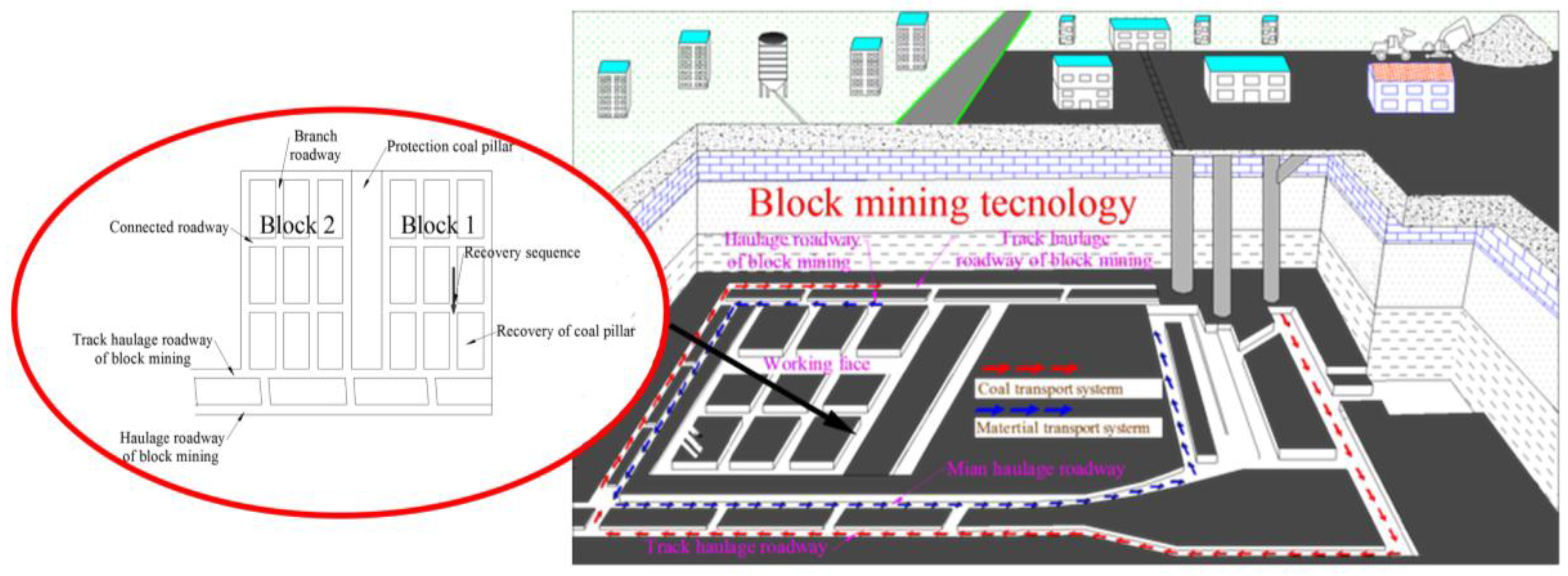
2.1. Mining System
Figure 1 shows a typical SBM system and the arrangement in the working face. The recovery coals followed the transmission path: block working face → haulage roadway of SBM → main haulage roadway → main shaft, and the materials moved along the following route: auxiliary shaft → track haulage roadway → track haulage roadway of SBM → block working face. In the working face, four branch roadways and three connected roadways constituted a mining block, and the protection coal pillar was set between the two blocks for isolation. The coal pillars in each block were recovered in a drawing-back manner from the top to the bottom.
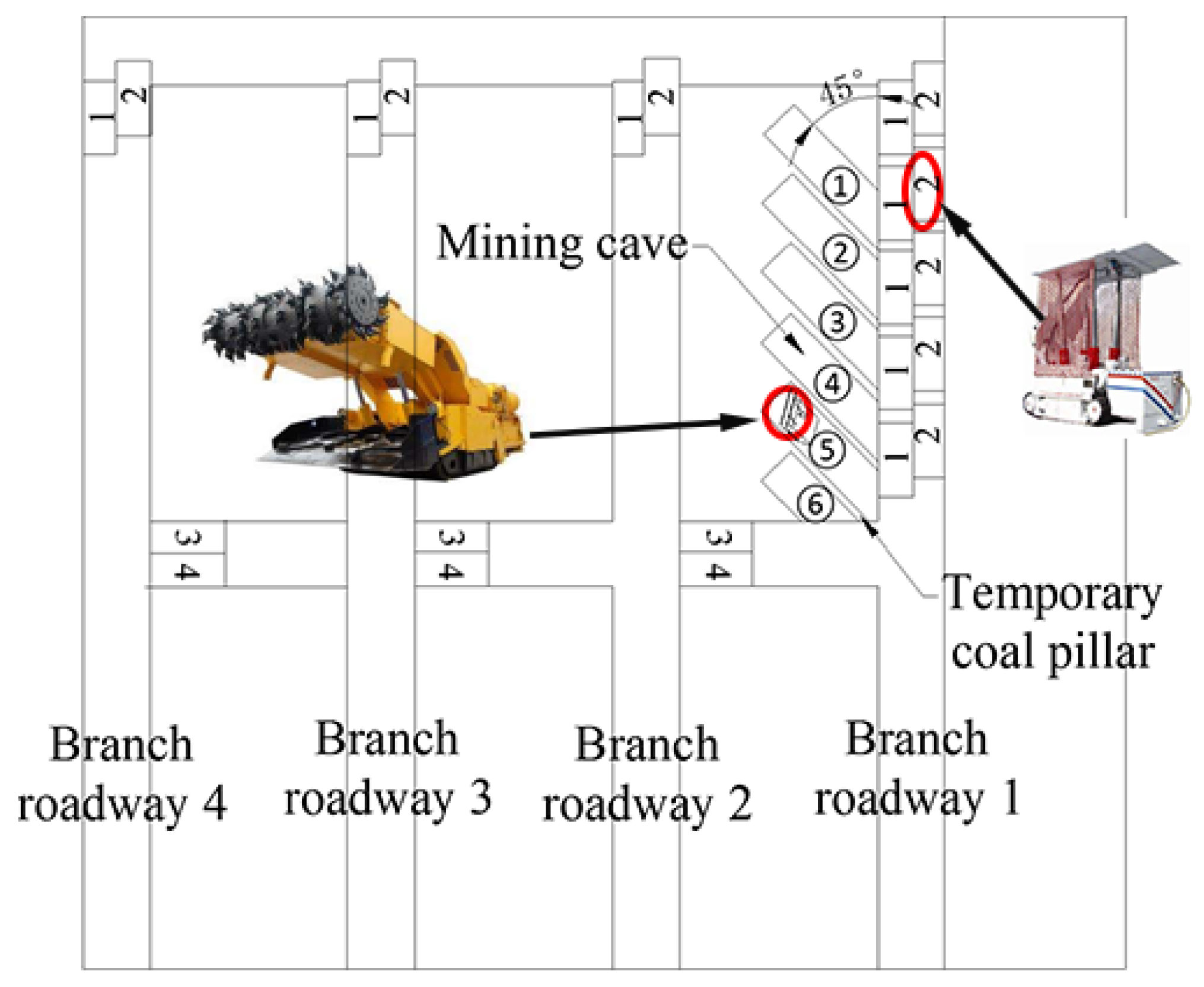
2.2. Main Equipment and the Related Parameter Settings in the Working Face
In SBM, the used equipment mainly includes crawler-type movable hydraulic supports and continuous miners. During the recovery process of coal pillars, a temporary coal pillar is set between the two mining caves; four crawler-type movable hydraulic supports in total are set for ensuring the miner’s safety and continuity in coal cutting and loading. As shown in Figure 2, two sets of crawler-type movable hydraulic supports are arranged; specifically, Supports 1 and 2 are included in a set and arranged in the branch roadway, whereas Supports 3 and 4 are included in the other set and arranged in the connected roadway between the two neighboring branch roadways. The widths of both the branch roadway and connected roadway are set at 5 m; the length of the mining cave is no greater than 11 m, whereas the width of the mining cave is 3.3 m; the angle between the mining cave and branch roadway is ~45°, and a 0.5–1.5 m coal pillar is set between the two mining caves.
3. Development Mechanisms of WFZ in SBM
3.1. Characteristics of Overlying Strata Destruction in SBM
3.1.1 Traditional Longwall Caving Method
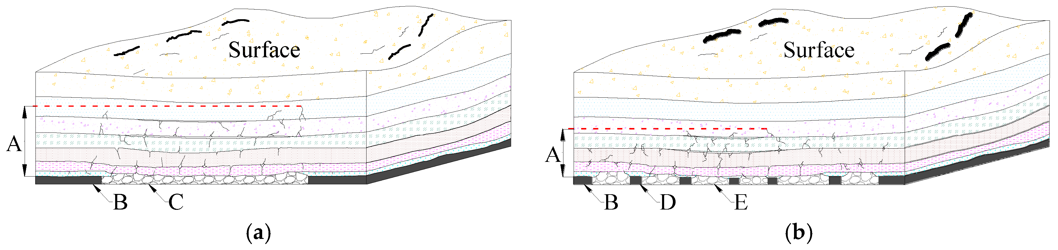
During the traditional fully-mechanized excavating process, the goaf roof collapsed with the heading in the working face, accompanied by the collapse of the main roof, which would finally fracture the main key strata. In particular, during the mining in the shallow coal seams in Western China, traditional longwall caving may lead to the surface’s step submergence and generate plastic failures over a large scale [15]. Figure 3a shows the movement characteristics of overlying strata during the rational longwall caving.
3.1.2. SBM Method
During the SBM process, both the immediate roof and main roof collapsed with the heading in the working face. The protection coal pillars were set between each of the two blocks for bearing the load of the overlying rocks and can reduce the destruction on the overlying strata to a certain degree and, thus, restrict the development of water-flowing fissures. In the meantime, the surface subsidence will be controlled effectively. Figure 3b shows the deformation in the surrounding rocks.
3.2. Main Controlling Factors of HWFZ in SBM
According to the SBM working face’s particularity and the overlying strata’s destruction characteristics, the main controlling factors of HWFZ as shown in Figure 4 are as follows:
(1) Mining Height
Mining height directly affects the development height of three fissure zones in the overlying strata [16]. Moreover, according to the prediction formula of HWFZ as described in The Regulation, only mining height affects HWFZ.
(2) Width of the Protection Coal Pillar
Protection coal pillar bears the loads of all the strata after mining. The arrangement pattern of the protection coal pillars would significantly affect the overlying strata’s destruction range and HWFZ.
(3) Length of the Block
The length of block is also a parameter in the working face affecting HWFZ and reflecting the direct effects of excavation length on the overlying strata’s plastic failure, deformation, and redistribution of stress.
(4) Mining Depth
Based on the theories in rock mechanics [17], crustal stress increased with increasing depth. At different coal mining depths, the working face would sustain different magnitudes of crustal stresses. Mining depth also affects the overlying strata’s destruction range to a certain degree.
Under a certain geological condition, the burial depth generally remains unchanged. Therefore, the mining height and the length of the block and the width of the protection coal pillars should be appropriately set for effectively controlling the development of water-flowing fissures, so that WFZ will not penetrate into the aquifer, avoiding the wastage of water resources.
3.3. Establishment of the Mechanical Model and Analysis of Bending Deformation
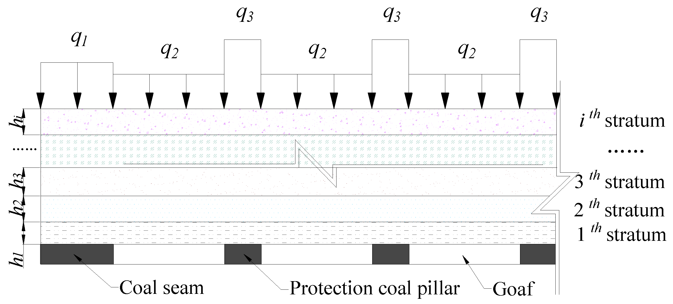
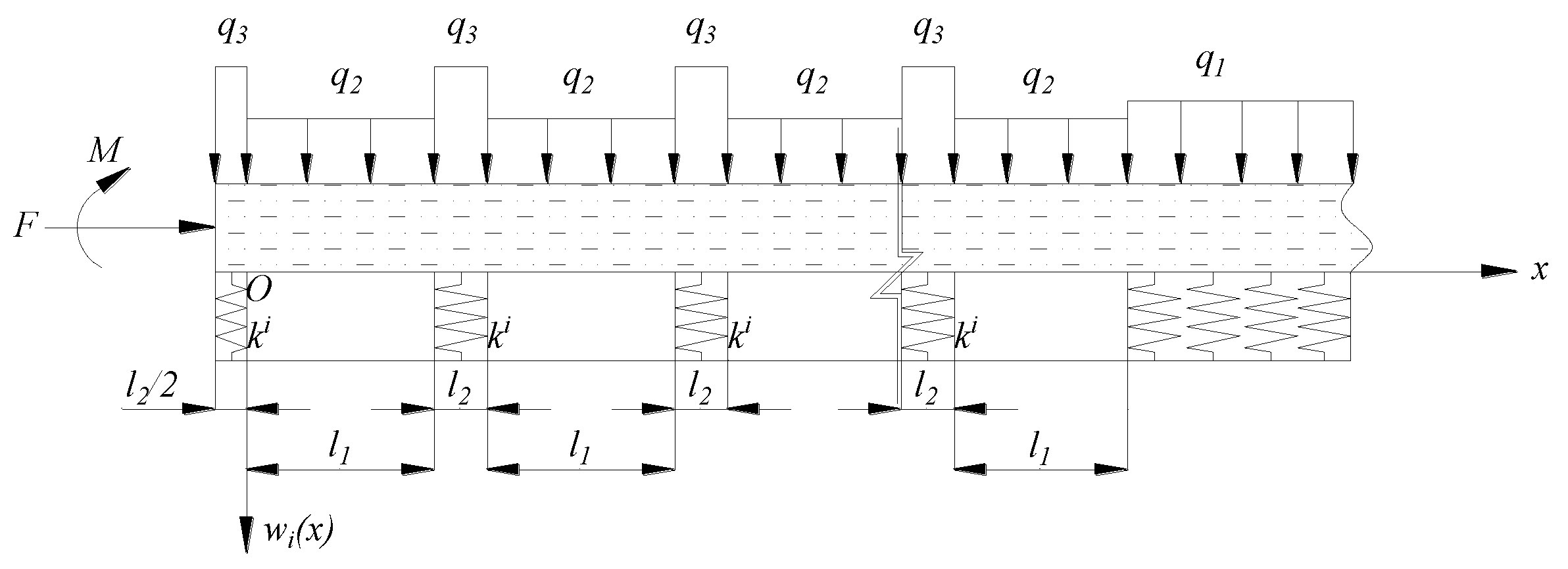
To explore the development rule of WFZ in the SBM, we first determined HWFZ based on the plastic failure height of the strata above the working face. As shown in Figure 5, by taking the ith stratum above the coal seam as the example, the applied loads were assumed to be uniformly distributed and simplified as , , and , meanwhile, the strata below and coals were simplified as Winkler elastic foundation. Assuming the length of each block as l1, the width of the protection coal pillar is labeled as l2, the thicknesses of various layers of strata above the coal seam were denoted as h1, h2, h3,…, hm, and the total thickness of the bed rocks above the coal seam (including the ith layers in total) is equal to (i = 1, 2, 3,…, m) and the mechanical model of the superposed beam on the elastic foundation was established for subsequent analysis. Due the burial depth of coal seams in Western China being relatively shallow, the stress concentration on the coal pillar is low. When the stress is not large enough, time has little effect on the protection coal pillars [18,19]. In the meantime, the coal pillars width among mining caves are small, and they will fail to support the roof at the end. Therefore, the coal pillars among mining caves, time, etc., were not taken into account.
The load on the ith stratum can be written as:
where γ, d, d’, and j denote the rock’s bulk density (KN·m-3), the burial depth (m), the potential falling height (m), and the coefficient of stress concentration, respectively.
The elastic foundation coefficients satisfied the following equation:
where ki denotes the elastic foundation coefficient of coal seam and the (i − 1)th bed rock above the coal seam; kc denotes the coals’ elastic foundation coefficient; k1, k2, k3, …, ki-1 denote the elastic foundation coefficients of various strata.
As shown in Figure 5, under these conditions, it is a positive symmetrical structure. To simplify the calculation, half of the structure in the model was selected for further analysis. Next, two different conditions will be described in detail depending on whether there is an even or odd number of blocks.
3.3.1. The Calculation Method—Even Number of Blocks
First, at the midpoint of the (n/2)th protection coal pillar was selected as the symmetry point. Next, using the intersection point between the (n/2)th protection coal pillar and the (n/2)th goaf as the origin, a coordinate system was established, as shown in Figure 6, in which the displacement function w(x) was adopted as the unknown quantity.
According to Winkler’s assumption [20,21,22], the subsidence of any point on the surface of the foundation is proportional to the pressure on the unit area. Then the foundation is regarded as a series of independent springs on the rigid basement. When a pressure of q is set on certain point of the surface of the foundation, there will be a partial subsidence w in that point while, in other places, no more subsidence will appear, due to the springs being independent from each other. Therefore, the protection coal pillars can be assumed to be springs which are independent from each other. The coal seam on the right is assumed to be a semi-infinite elastic foundation and the overlying strata can be assumed as a semi-infinite beam. The deflection equation of the beam in the overlying strata can be written as:
where EI denotes the beam section’s flexural rigidity.
Then, a characteristic coefficient of was set and solved. The general solution to Equation (3) can be written as:
The relationship between the foundation coefficient and the thickness of coal strata can be written as [23]:
where Ec denotes the coal’s elastic modulus and Ei denotes the ith stratum’s elastic modulus.
Since the structure of the model and the load are symmetrical, the deflection curve and the bending moment curve of the beam are distributed symmetrically, while the rotating angle curve and shear force curve are distributed anti-symmetrically. Therefore, the rotating angle and shear force in the symmetric are equal to 0. According to the previous assumption, the beam on the right is assumed to be a semi-infinite beam, based on the qualitative analysis, when , , and . The boundary condition of the beam can be written as:
The continuity condition can be described as below. The deflection, bending moment, rotating angle, and shearing force at the connection point among the coal pillar, stope, and coals are equal.
Finally, by substituting the boundary conditions and continuity condition into Equation (4), the parameters A1, B1, C1, D1, A2, B2, C2, D2,……An+1, Bn+1, Cn+1, and Dn+1 were solved, i.e., the roof’s bending subsidence equation w(x) and the bending moment equation M(x) were acquired.
3.3.2. The Calculation Method—Odd Number of Blocks
First, at the midpoint of the [(n+1)/2]th goaf was selected as the symmetry point, and the mechanical model of the ith stratum was established, as shown in Figure 7.
According to the elastic footing beam theory, the general expression of the deflection curve of the ith stratum in the overlying rocks can be written as:
The boundary condition of the model can be written as:
The continuity condition can also be described as below. The deflection, bending moment, rotating angle, and shearing force at the connection point among coal pillar, stope, and coals are equal.
Similarly, by substituting the boundary conditions and continuity condition into Equation (7), the parameters A1’, B1’, C1’, D1’, A2’, B2’, C2’, D2’,……An+1’, Bn+1’, Cn+1’, and Dn+1’ were solved, i.e., the deflection curves and bending moment curves of various segments of the rock beam were acquired.
3.4. Calculation of HWFZ
According to rectangle section beam theory, the maximum tension stress of the beam can be calculated by:
where Mimax denotes the maximum bending moment of the ith stratum in the overlying strata.
Based on the maximum normal stress theory, if the strata would not be fractured, and the following expression should be satisfied:
where [σi] denotes the tensile strength of the ith stratum in the overlying rock.
If Equation (10) is satisfied, the stratum would not be fractured and no water-flowing fissure zone would be generated; otherwise, the fissure zone would be formed. The development height of the water-flowing fissure zone can be calculated by the thicknesses of various fractures strata:
4. A Case Study
4.1. Background of the Project
The reserves of coal resources are abundant in the western region of China, and the burial depth of coal seams is generally within 100~200 m, which belongs to the shallow buried coal seam. Additionally, the geological structure is simple and the coal quality is good However, the western part of China is an arid and semi-arid area, with poor water resources, sparse vegetation, and a fragile ecological environment. The experimental mining area is located in the territory of Inner Mongolia, Erdos City, and the surface is covered with eolian sand. In addition to serious soil erosion, the area belongs to the typical semi-arid and semi-desert climate, which has a strong seasonality. The experimental area covered an area of 32,400 m2, and the amount of predicted coal recovery was 93,000 tons. The #3 coal seam in the working face showed a simple, but stable, structure and slightly variable thickness, with an average burial depth and an average thickness of 110 m and 4 m, respectively, which can be regarded as a nearly flat seam. The experimental mine is a typical shallow buried coal mine in Western China. From the bottom to the top, the coal top consisted of medium sandstones, siltstones, mudstones, fine sandstones, hipparion red clays, and drift-sands. The aquifer was above the red clay layer. Figure 8 shows the columnar patterns of the strata in the mine and the related mechanical parameters.
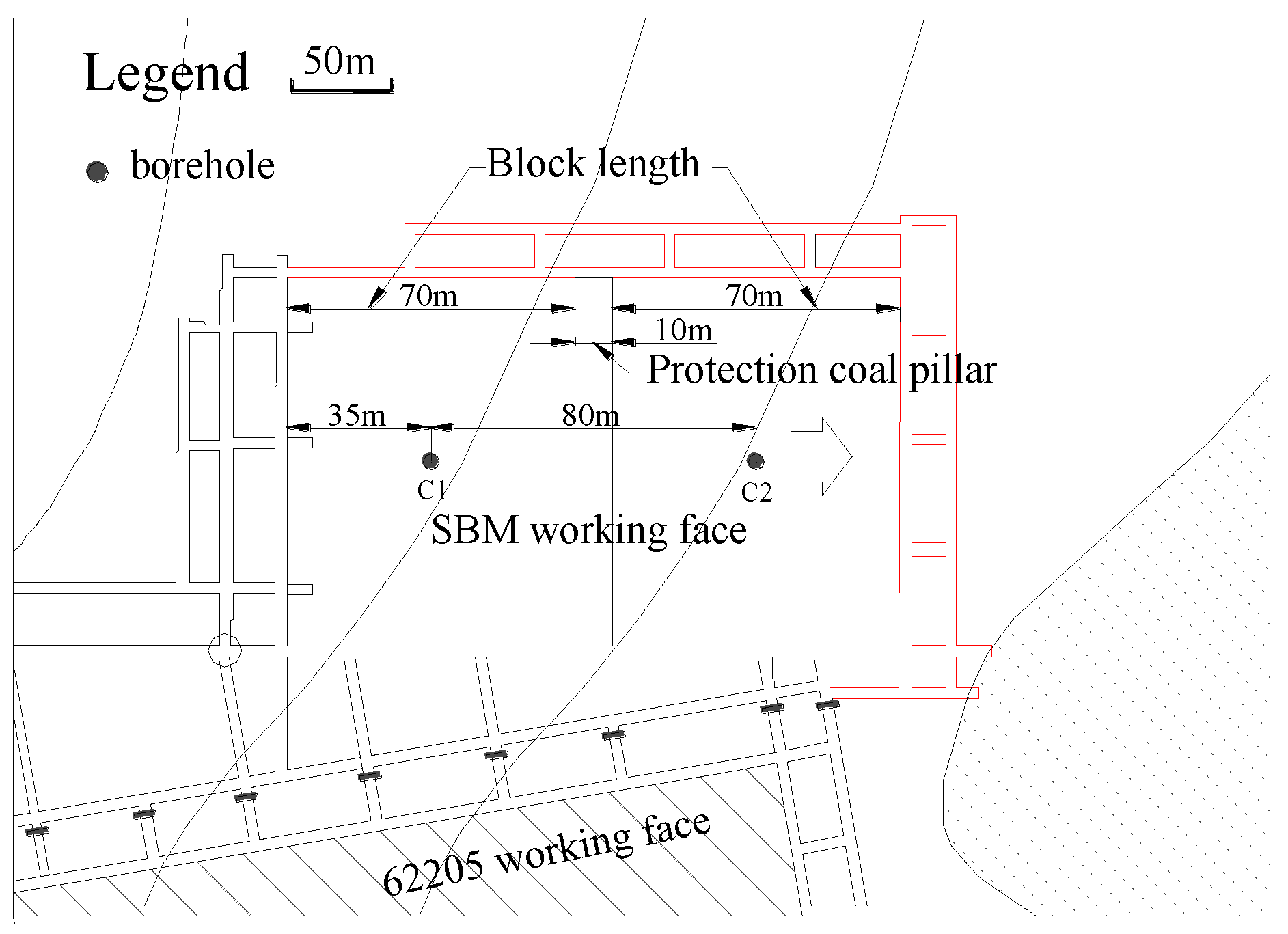
The experimental region was divided into two blocks for the recovery of coals, during which the mining height, the advancing length in each block, and the width of the protection coal column between the blocks were ~4, ~70, and ~10 m, respectively. Figure 9 shows the specific arrangement of the working face.
4.2. Development of HWFZ
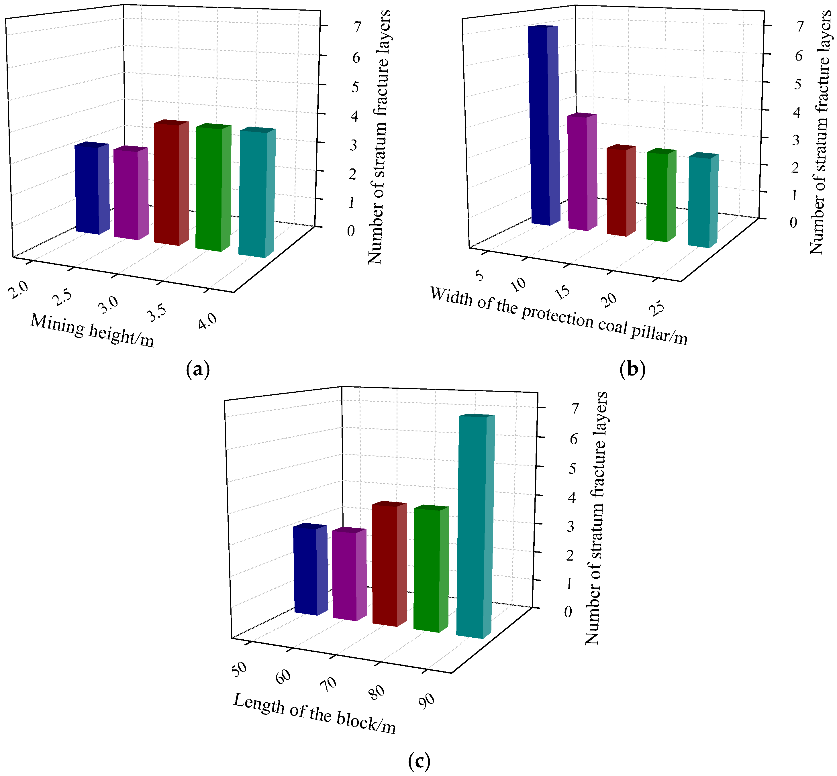
According to the specific parameters of the project as shown in Figure 8, the key strata was first identified [24]. The silt-sandstone layer (at a depth of 17.0 m) was the inferior key stratum, while the silt-sandstone layer at a depth of 20.0 m was the key stratum. Based on the previous experiments, the stress concentration coefficient was set in the range, i.e., j = ~1–3. Table 1 lists the specific calculation scheme. When two blocks were recovered, water diversion heights under different mining depths, block lengths, and protection pillar widths were calculated, and the results are shown in Figure 10.
As shown in Figure 10, with increasing mining height and block length, the stratum’s destruction height increased step by step; however, with increasing width of the protection coal pillar, the destruction height decreased gradually. Meanwhile, when the permeates varied within certain ranges, the number of stratum layers were unchanged. For example, when the width of the protection pillar varied within the range ~15–25 m, the destruction included three layers, with an accumulative height of ~40 m. In actual engineering we should first guarantee that the diversion fissure zone would not develop towards the aquifer; then, in order to enhance the coal column’s recovery ratio, the mining height and block length can be increased and the width of the protection coal pillar can be decreased.
5. Practical Application
5.1. Monitoring Method of HWFZ
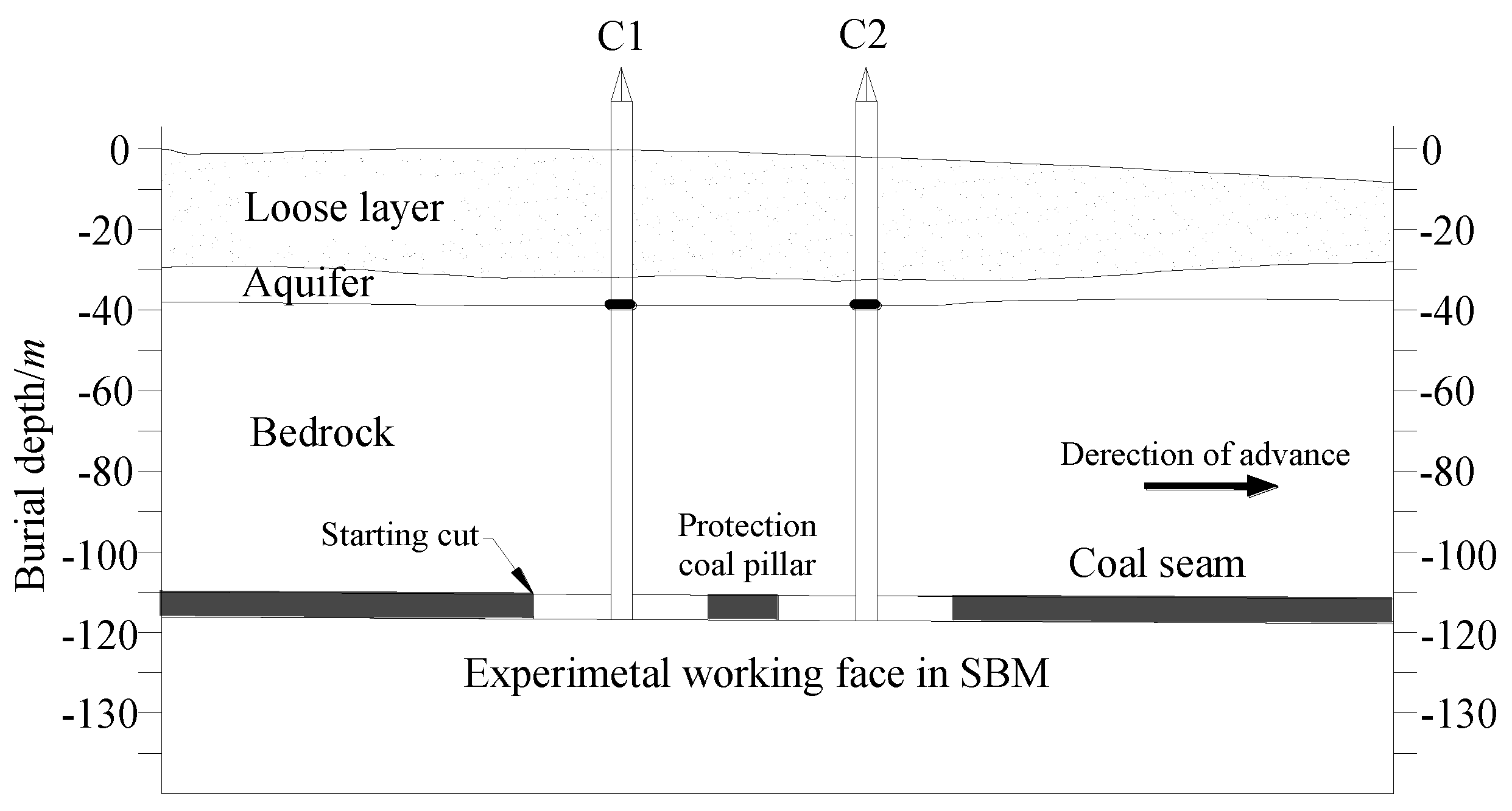
During the field SBM process, HWFZ was determined by the leakage of the drill hole washing fluid. After the recovery in the working face, two observation holes were arranged above the working face, C1 and C2, for measuring HWFZ. Figure 9 and Figure 11 display the arrangement of holes, from which C1 and C2 are found to be located at the center of the two working faces. The distance between C1 and open-off cut was 35 m, whereas the distance between C2 and open-off cut was 115 m. The drilled depths of both C1 and C2 were 114 m. The terminal hole position was the coal floor stratum, and the leakage of the washing fluid in the drilling process was monitored.
5.2. Analysis of the Monitored Data
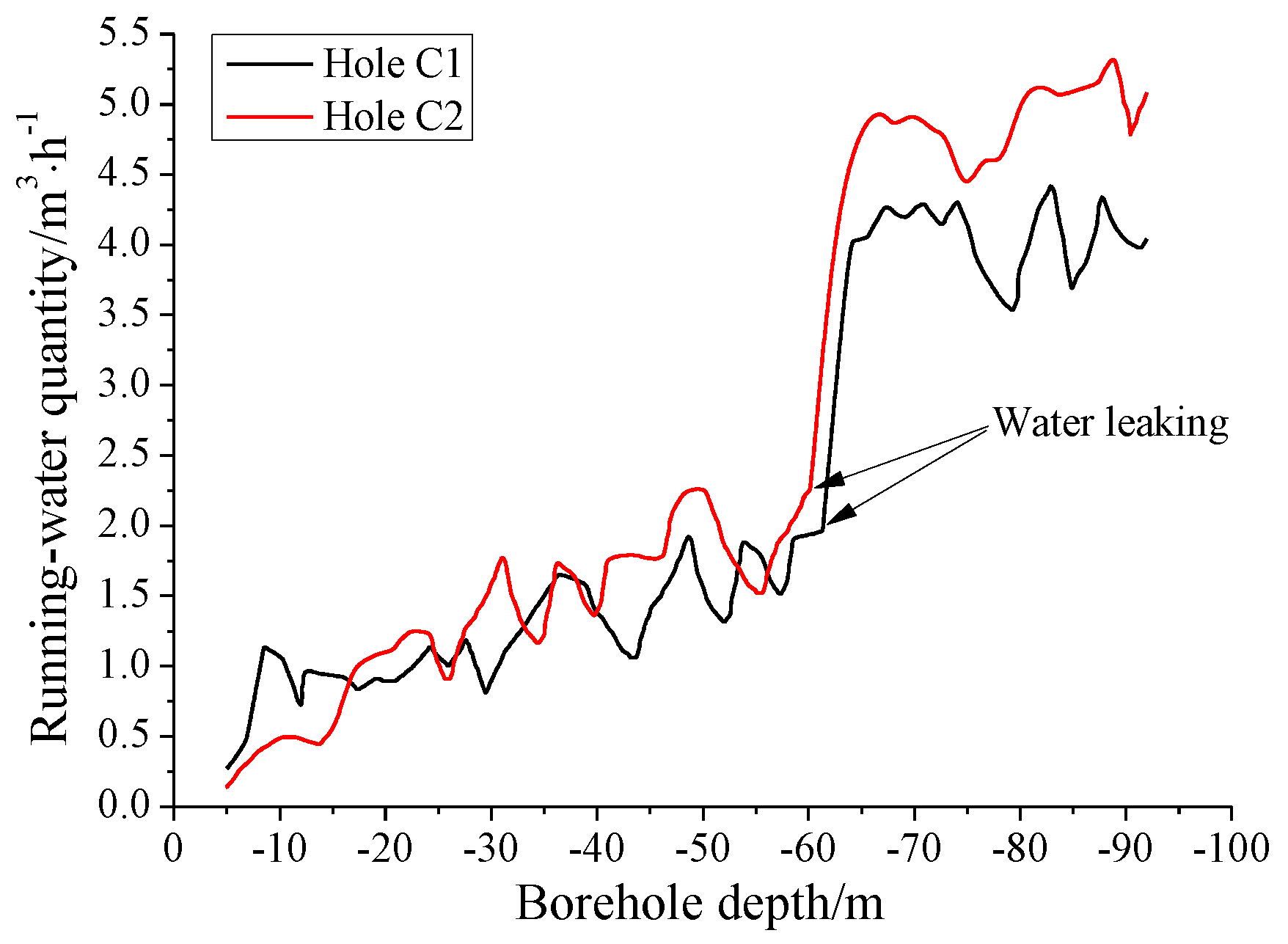
Figure 12 shows the variations in the leakages of washing fluid at C1 and C2 with the drilling depth. For Hole C1, when being drilled to −62.42 m, the measured leakage increased slightly from 0.27 m3/h to 1.93 m3/h, and the laminar cracks in frill core completely developed. With increasing drilling depth, the leakage rapidly increased to 4.03 m3/h, showing a significant increase in the amplitude; the recovery ratio of core was lower than 50%, the core hole well developed, and the narrow cracks along different directions formed. As the drilling depth increased further, the leakage fluctuated within a small range, indicating that the measured HWFZ was ~47.98 m.
For Hole C2, when being drilled to −60.34 m, the leakage of the washing liquid increased from 0.14 m3/h to 2.27 m3/h; the recovery ratio of the drill core was ~78%, showing narrow and no obvious laminar cracks. As the drilling depth increased, the leakage rapidly increased to 4.58 m3/h in a fluctuant pattern, crushing the rock core. With the further increase in the drilling depth, the leakage varied slightly. Thus, the development vertex of WFZ and the HWFZ were determined as approximately −60.34 m and 50.06 m, respectively.
5.3. Comparison between Measured and Predicted Results of HWFZ
Given the mechanical parameters of various strata as shown in Figure 9, the water-flowing height was calculated according to the prediction equation , as described in Appendix 7 in The Regulation. In addition, the HWFZ was also calculated based on the mechanical theory. The predicted and theoretically-calculated values were 75.5 m and 50.3 m, respectively, as shown in Table 2. According to the field measured data, the HWFZ in SBM working face was ~49 m, i.e., the water-flowing fissures did not develop towards the aquifer. The comparison results demonstrate that the predicted value deviates significantly from the measured data, while the calculated value based on the proposed mechanical model almost fit well with the field-measured data, further verifying the high reliability of the proposed calculation model.
6. Conclusions
(1) Recovering coal resources in irregular blocks and corners using SBM was proposed, and the basic characteristics of the overlying strata movements were analyzed. The key factors affecting the development of water-flowing fissure zones, namely, mining depth, the width of the protection coal pillar among blocks, and the block length, were determined.
(2) Based on the elastic foundation beam theory, the mechanical model for calculating HWFZ in SBM was established. According to the calculation results, the number of the strata’s destruction layers remained unchanged, when the main controlling factors varied within certain ranges. Therefore, under the premise that HWFZ remained unchanged, the mining height and block length should be as great as possible, while the width of the protection coal pillar should be as small as possible to maximize the recovery ratio.
(3) According to the field measurements, the HWFZ in the experimental working face after SBM was ~49 m and almost fit well with the theoretically calculated value (50.3 m). This verified the correctness of the established calculation model in this study, suggesting that HWFZ in the SBM working face can be accurately predicted based on the established calculation model. Therefore, this calculation model shows great significance to the improvement of coal recovery, water resource protection, and the construction of green ecosystem.
Acknowledgments
This study was supported jointly by the National Key Basic Research Program of China (2015CB251600), the National Natural Science Foundation of China (51374197), and the Independent Project of State Key Laboratory of Coal Resources and Safe Mining (CUMT) of China (SKLCRSM12X06).
Author Contributions
Yun Zhang, Shenggen Cao and Lixin Lan did thorough literature search. Yun Zhang drafted the manuscript. Rui Gao and Hao Yan reviewed the final paper and made important suggestions and recommendations for paper revision.
Conflicts of Interest
The authors declare no conflict of interest.
References
- Ye, G.X.; Jiang, F.X.; Liu, P.L.; Feng, Z.Q.; Wang, D.Z. Design and optimization of efficient mining technology in boundary coal recovery. J. Univ. Sci. Technol. B. 2007, 29, 655–659. [Google Scholar]
- Zhang, N.H. Study on the Theory and Practice about Mechanized Mining Technology of Bound Coal at Irregular Block Section. Ph.D. Thesis, China University of Mining & Technology, Xuzhou, China, 2011. [Google Scholar]
- Zhou, M.P. Research on Continuous Mining Methods and Rock Control Technology. Ph.D. Thesis, China University of Mining & Technology, Xuzhou, China, 2014. [Google Scholar]
- Cao, S.G.; Cao, Y.; Jiang, H.J. Research on catastrophe instability mechanism of section coal pillars in block mining. J. Min. Saf. Eng. 2014, 31, 908–913. [Google Scholar]
- Zhang, W.; Zhang, D.S.; Wu, L.X.; Wang, H.Z. On-site radon detection of mining-induced fractures from overlying strata to the surface: A case study of the Baoshan coal mine in China. Energies 2014, 7, 8483–8507. [Google Scholar] [CrossRef]
- Zhang, D.S.; Fan, G.W.; Liu, Y.D.; Ma, L.Q. Field trials of aquifer protection in longwall mining of shallow coal seams in China. Int. J. Rock Mech. Min. Sci. 2010, 47, 908–914. [Google Scholar] [CrossRef]
- Zhang, D.S.; Fan, G.W.; Ma, L.Q.; Wang, X.F. Aquifer protection during longwall mining of shallow coal seams: A case study in the Shendong coalfield of China. Int. J. Coal Geol. 2011, 86, 190–196. [Google Scholar] [CrossRef]
- Zhang, J.C.; Shen, B.H. Coal mining under aquifers in China: A case study. Int. J. Rock Mech. Min. Sci. 2004, 41, 629–639. [Google Scholar] [CrossRef]
- Miao, X.X.; Chen, R.H.; Bai, H.B. Fundamental concepts and mechanical analysis of water-resisting key strata in water-preserved mining. J. China Coal Soc. 2007, 32, 562–564. [Google Scholar]
- Miao, X.X.; Wang, A.; Sun, Y.J.; Wang, L.G.; Pu, H. Research on basic theory of mining with water resources protection and its application to arid and semi-arid mining areas. Chin. J. Rock Mech. Eng. 2009, 28, 217–227. [Google Scholar]
- Fan, G.W.; Zhang, D.S. Mechanisms of aquifer protection in underground coal mining. Mine Water Environ. 2015, 34, 95–104. [Google Scholar] [CrossRef]
- Fan, L.M.; Zhang, X.T.; Xiang, M.X.; Zhang, H.Q.; Shen, T.; Lin, P.X. Characteristics of ground fissure development in high intensity mining area of shallow seam in Yushenfu coal fiel. J. China Coal Soc. 2015, 40, 1442–1447. [Google Scholar]
- Fan, L.M.; Ma, X.D.; Ji, R.J. Progress in engineering practice of water-preserved coal mining in western eco-environment frangible area. J. China Coal Soc. 2015, 40, 1711–1717. [Google Scholar]
- Zhou, M.P.; Cao, S.G.; Jiang, X.J. The law of rock pressure in the stope with blocking mining by the continuous miner. J. Min. Saf. Eng. 2014, 31, 413–417. [Google Scholar]
- Huang, Q.X. Ground pressure behavior and definition of shallow coal seams. Chin. J. Rock Mech. Eng. 2009, 28, 217–227. [Google Scholar]
- Qian, M.G.; Shi, P.W.; Xu, J.L. Mining Pressure and Strata Control, 2nd ed.; China University of Mining & Technology Press: Xuzhou, China, 2010; pp. 115–116. [Google Scholar]
- Hoek, E.; Brown, E.T. Underground Excavations in Rocks, 1st ed.; Institution of Mining and Metallurgy: London, UK, 1980; pp. 382–395. [Google Scholar]
- Tan, T. The mechanical problems for the long-term stability of underground galleries. J. Rock Mech. Eng. 1982, 1, 7–26. [Google Scholar]
- Li, J.P. Mining Rock Mechanics, 1st ed.; Metallurgical Industry Press: Beijing, China, 2011; pp. 50–55. [Google Scholar]
- Zhang, J.X.; Li, J.; An, T.L.; Huang, Y.L. Deformation characteristic of key stratum overburden by raw waste backfilling with fully-mechanized coal mining technology. J. China Coal Soc. 2011, 36, 357–362. [Google Scholar]
- Yang, X.X. The feature of foundation pressure on winkler foundation beam with one fixed end and its application. Eng. Mech. 2006, 23, 76–79. [Google Scholar]
- Huang, Y.L.; Li, J.M.; Song, T.Q.; Kong, G.Q.; Li, M. Analysis on filling ratio and shield supporting pressure for overburden movement control in coal mining with compacted backfilling. Energies 2017, 10, 31. [Google Scholar] [CrossRef]
- Deng, X.J.; Zhang, J.X.; Huang, P.; Zhang, Q.; Hao, X.F. Roof movement characteristics in extra thick coal seam mining with the upward slicing filling technology. China Coal Soc. 2015, 40, 994–1000. [Google Scholar]
- Qian, M.G.; Miao, X.X.; Xu, J.L. Key Strata Theory of Strata Control, 1st ed.; China University of Mining & Technology Press: Xuzhou, China, 2003; pp. 16–20. [Google Scholar]
Figure 1.
A typical shortwall block mining (SBM) system and the layout of the working face.

Figure 2.
Illustration of the recovery process of coal pillars and main equipment.

Figure 3.
Characteristics of the overlying strata in the stope: (a) the movement characteristics of the overlying strata by the traditional longwall caving method; and (b) the movement characteristics of the overlying strata by the SBM method. A—the height of the water-flowing fissure zone (HWFZ); B—Coal seam; C—Longwall mining working face; D—Protection coal pillar; E—SBM working face.

Figure 4.
Illustration of the main controlling factors. A—HWFZ; a—Mining height; b—Width of the protection coal pillar; c—Length of block; d—Mining depth.
Figure 4.
Illustration of the main controlling factors. A—HWFZ; a—Mining height; b—Width of the protection coal pillar; c—Length of block; d—Mining depth.
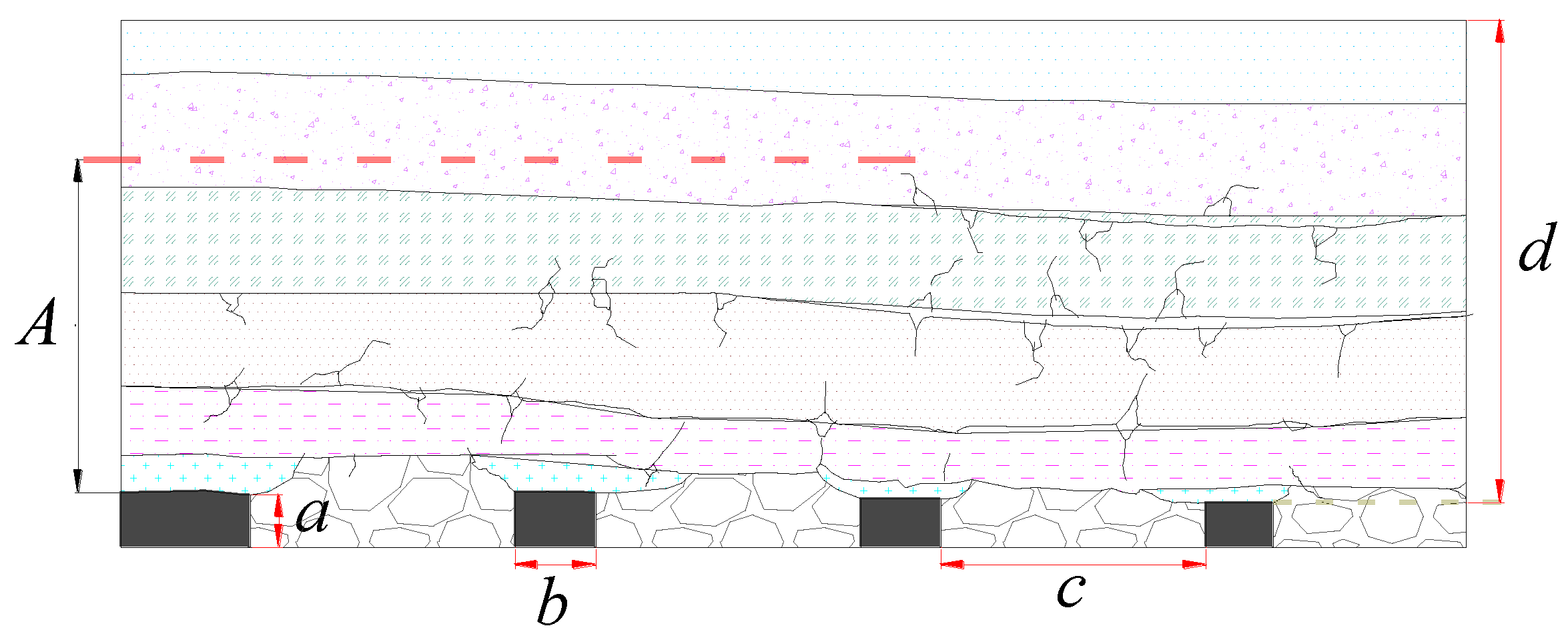
Figure 5.
Applied forces on the basic environment in a stope.

Figure 6.
Mechanical model of the strata when the number of blocks was even.

Figure 7.
Mechanical model of the strata when the number of blocks was odd.
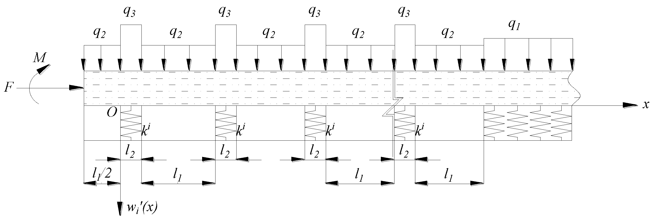
Figure 8.
Columnar patterns of the strata and the related physical and mechanical properties.
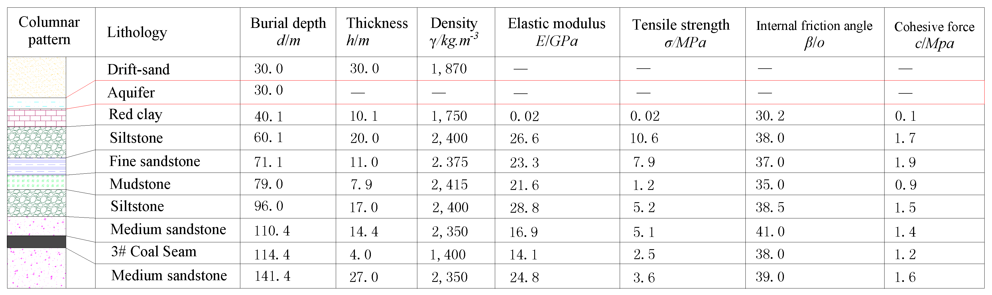
Figure 9.
Arrangement of the working face in SBM.

Figure 10.
Variations in the number of stratum fracture layers with different effecting factors: (a) variation in the number of stratum fracture layers with mining height; (b) variation in the number of stratum fracture layers with the width of the protection pillar; and (c) variation in the number of stratum fracture layers with block length.

Figure 11.
Arrangement of the aquifer and the holes.

Figure 12.
Relationship between the leakage and drilling depth.

Table 1.
Calculation scheme.
| Scheme | Mining Height/m | Width of Protection Coal Pillar/m | Block Length/m |
|---|---|---|---|
| 1 | 2/2.5/3.0/3.5/4.0 | 10 | 70 |
| 2 | 4 | 5/10/15/20/25 | 70 |
| 3 | 4 | 10 | 50/60/70/80/90 |
Table 2.
Comparison between the measured and predicted results of HWFZ.
| HWFZ | Measured Results | Predicted Results According to The Regulation | Predicted Results Based on the Mechanical Model | |
| C1 | C2 | |||
| 47.98 m | 50.06 m | 75 m | 50.3 m | |
© 2017 by the authors. Licensee MDPI, Basel, Switzerland. This article is an open access article distributed under the terms and conditions of the Creative Commons Attribution (CC BY) license (http://creativecommons.org/licenses/by/4.0/).
Share and Cite
MDPI and ACS Style
Zhang, Y.; Cao, S.; Lan, L.; Gao, R.; Yan, H. Analysis of Development Pattern of a Water-Flowing Fissure Zone in Shortwall Block Mining. Energies 2017, 10, 734. https://doi.org/10.3390/en10050734
AMA Style
Zhang Y, Cao S, Lan L, Gao R, Yan H. Analysis of Development Pattern of a Water-Flowing Fissure Zone in Shortwall Block Mining. Energies. 2017; 10(5):734. https://doi.org/10.3390/en10050734
Chicago/Turabian StyleZhang, Yun, Shenggen Cao, Lixin Lan, Rui Gao, and Hao Yan. 2017. "Analysis of Development Pattern of a Water-Flowing Fissure Zone in Shortwall Block Mining" Energies 10, no. 5: 734. https://doi.org/10.3390/en10050734
Note that from the first issue of 2016, this journal uses article numbers instead of page numbers. See further details here.