
Frequency-Adaptive Modified Comb-Filter-Based Phase-Locked Loop for a Doubly-Fed Adjustable-Speed Pumped-Storage Hydropower Plant under Distorted Grid Conditions

Abstract
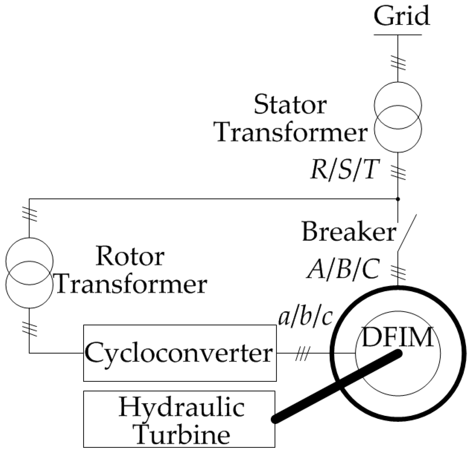
:1. Introduction
2. CF-PLL
3. FAMCF-PLL
3.1. MCF-PLL
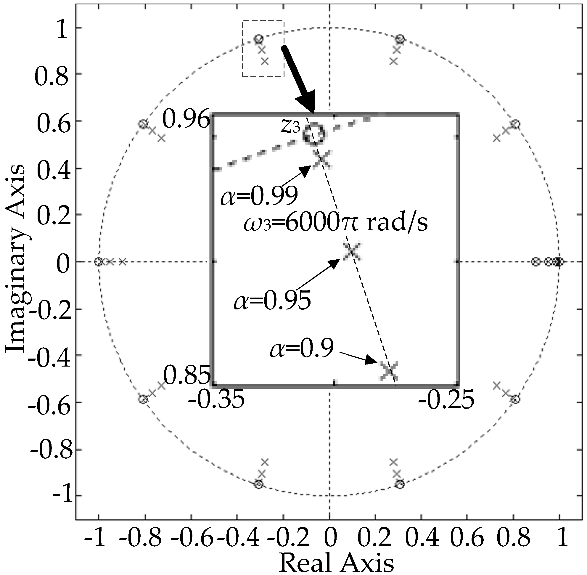
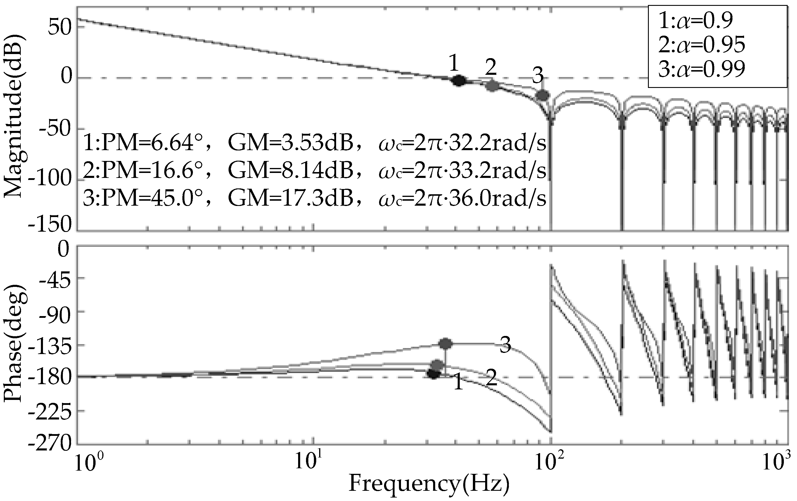
3.2. Discrete Model of FAMCF-PLL
3.3. FAMCF-PLL Realization
- (1)
- At sample time k, adding the grid voltages’ q axis component, x (k), to A (i − 1); then saving the result to array A (i).
- (2)
- Computing sample order N using Equation (14), .
- (3)
- Adding y (k) to , then saving the result to array B (i).
- (4)
- .
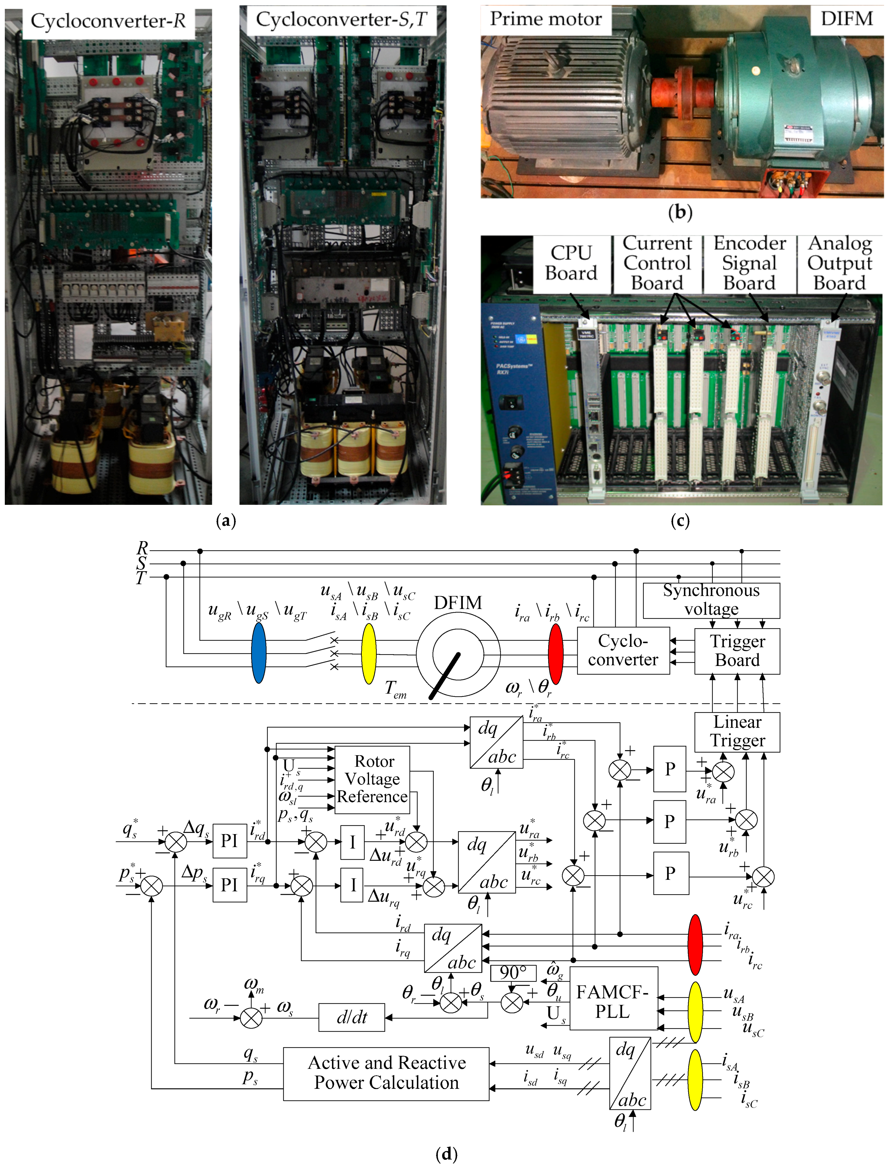
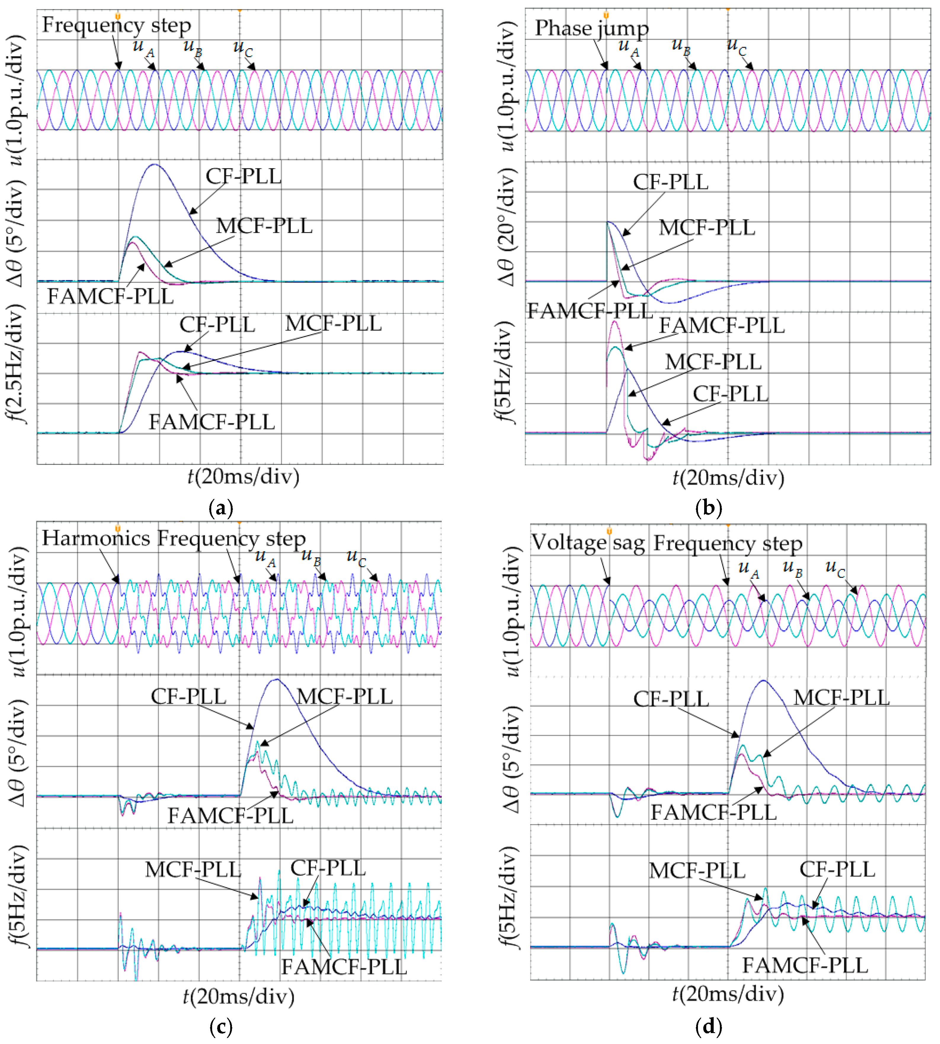
4. Experimental Results
- Condition 1: 40 ms, the grid voltage undergoes a frequency step change of +5 Hz.
- Condition 2: 40 ms, the grid voltage undergoes a phase angle jump of +40°.
- Condition 3: 40 ms, the grid voltage undergoes a harmonics injection of 20% fifth and 10% seventh harmonic components. At 100 ms, the grid voltage undergoes a frequency step change of +5 Hz.
- Condition 4: 40 ms, the voltage amplitude of phase A sags by 50% and the voltage amplitude of phase B sags by 30%. At 100 ms, the grid voltage undergoes a frequency step change of +5 Hz.
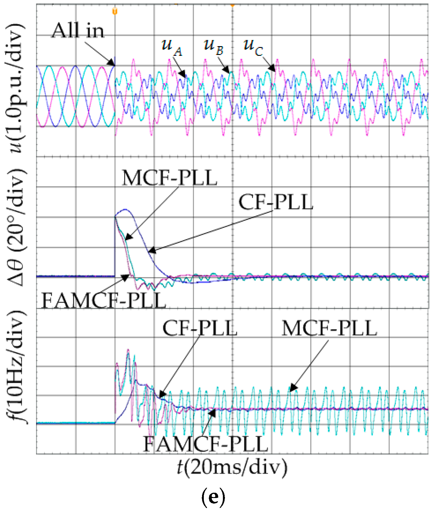
- Condition 5: 40 ms, the frequency step change, phase angle jump, harmonics injection, and voltage sag occur at the same time.
5. Conclusions
Acknowledgments
Author Contributions
Conflicts of Interest
Appendix A
References
- Bose, B.K. Global energy scenario and impact of power electronics in 21st century. IEEE Trans. Ind. Appl. 2013, 60, 2638–2651. [Google Scholar] [CrossRef]
- Hadjipaschalis, I.; Poullikkas, A.; Efthimiou, V. Overview of current and future energy storage technologies for electric power applications. Renew. Sustain. Energy Rev. 2009, 13, 1513–1522. [Google Scholar] [CrossRef]
- Padoan, A.C.; Kawkabani, B.; Schwery, A.; Ramirez, C.; Nicolet, C.; Simond, J.-J.; Avellan, F. Dynamical behavior comparison between variable speed and synchronous machines with PSS. IEEE Trans. Power Syst. 2010, 25, 1555–2797. [Google Scholar] [CrossRef]
- Pannatier, Y.; Nicolet, C.; Kawkabani, B. Dynamic behavior of a 2 variable speed pump-turbine power plant. In Proceedings of the International Conference on Electrical Machines, Algarve, Portugal, 6–9 September 2008; pp. 1–6. [Google Scholar]
- Wu, B.; Pontt, J.; Rodriguez, J.; Bernet, S.; Kouro, S. Current-source converter and cycloconverter topologies for industrial medium-voltage drives. IEEE Trans. Ind. Electron. 2008, 55, 2786–2797. [Google Scholar]
- Nian, H.; Song, Y. Direct power control of doubly fed induction generator under distorted grid voltage. IEEE Trans. Power Electron. 2014, 29, 894–905. [Google Scholar] [CrossRef]
- Ma, J.; Qiu, Y.; Li, Y.; Zhang, W.; Song, Z.; Thorp, J.S. Research on the impact of DFIG virtual inertia control on power system small-signal stability considering the phase-locked loop. IEEE Trans. Power Syst. 2017, 32, 2094–2105. [Google Scholar] [CrossRef]
- Zhi, D.W.; Xu, L. Direct power control of DFIG with constant switching frequency and improved transient performance. IEEE Trans. Energy Convers. 2007, 22, 110–118. [Google Scholar] [CrossRef]
- Geng, H.; Xu, D.W.; Wu, B. A novel hardware-based all-digital phase-locked loop applied to grid-connected power converters. IEEE Trans. Ind. Electron. 2011, 58, 1737–1745. [Google Scholar] [CrossRef]
- Zheng, Z.; Yang, G.; Geng, H. Coordinated control of a doubly-fed induction generator-based wind farm and a static synchronous compensator for low voltage ride-through grid code compliance during asymmetrical grid faults. Energies 2013, 6, 4660–4681. [Google Scholar] [CrossRef]
- Xi, X.Z.; Geng, H.; Yang, G. Enhanced model of the doubly fed induction generator-based wind farm for small-signal stability studies of weak power system. IET Renew. Power Gener. 2014, 8, 765–774. [Google Scholar] [CrossRef]
- Wang, Z.; Li, G.J.; Sun, Y.Z.; Ooi, B.T. Effect of erroneous position measurements in vector-controlled doubly fed induction generator. IEEE Trans. Energy Convers. 2010, 25, 59–69. [Google Scholar] [CrossRef]
- Salamah, A.M.; Finney, S.J.; Williams, B.W. Three-phase phase-lock loop for distorted utilities. IET Electr. Power Appl. 2007, 1, 937–945. [Google Scholar] [CrossRef]
- Donato, G.D.; Scelba, G.; Capponi, F.G.; Scarcella, G. Fault-decoupled instantaneous frequency and phase angle estimation for three-phase grid-connected inverters. IEEE Trans. Power Electron. 2016, 31, 2880–2889. [Google Scholar] [CrossRef]
- Wang, Y.F.; Li, Y.W. Analysis and digital implementation of cascaded delayed signal cancellation PLL. IEEE Trans. Power Electron. 2011, 26, 1067–1080. [Google Scholar] [CrossRef]
- Ciobotaru, M.; Teodorescu, R.; Blaabjerg, F. A New single-phase PLL structure based on second order generalized integrator. In Proceedings of the Power Electronics Specialists Conference, Jeju, Korea, 18–22 June 2006; pp. 1–6. [Google Scholar]
- Golestan, S.; Mousazadeh, S.Y.; Guerrero, J.M.; Vasquez, J.C. A critical examination of frequency-fixed second-order generalized integrator-based phase-locked loops. IEEE Trans. Power Electron. 2017, 32, 6666–6672. [Google Scholar] [CrossRef]
- Jovanovic-Dolecek, G.; Mitra, S.K. A new two-stage sharpened comb decimator. IEEE Trans. Circuits Syst. 2005, 52, 1414–1420. [Google Scholar] [CrossRef]
- Freijedo, F.D.; Doval-Gandoy, J.; Lopez, Ó.; Fernandez-Comesana, P.; Martinez-Penalver, C. A signal-processing adaptive algorithm for selective current harmonic cancellation in active power filters. IEEE Trans. Ind. Electron. 2009, 56, 2829–2840. [Google Scholar] [CrossRef]
- Golestan, S.; Monfared, M.; Freijedo, F.D.; Guerrero, J.M. Design and tuning of a modified power-based PLL for single-phase grid-connected power conditioning systems. IEEE Trans. Power Electron. 2012, 27, 3639–3650. [Google Scholar] [CrossRef]
- Golestan, S.; Guerrero, J.M. Conventional synchronous reference frame phase-locked loop is an adaptive complex filter. IEEE Trans. Ind. Electron. 2015, 62, 1679–1681. [Google Scholar] [CrossRef]
- Golestan, S.; Guerrero, J.M.; Vidal, A.; Yepes, A.G.; Doval-Gandoy, J. PLL with MAF-based prefiltering stage: Small-signal modeling and performance enhancement. IEEE Trans. Power Electron. 2016, 31, 4013–4019. [Google Scholar] [CrossRef]
- Gonzalez-Espin, F.; Figueres, E.; Garcera, G. An adaptive synchronous-reference-frame phase-locked loop for power quality improvement in a polluted utility grid. IEEE Trans. Ind. Electron. 2012, 59, 2718–2731. [Google Scholar] [CrossRef]
- Golestan, S.; Ramezani, M.; Guerrero, J.M.; Freijedo, F.D.; Monfared, M. Moving average filter based phase-locked loops: Performance analysis and design guidelines. IEEE Trans. Power Electron. 2014, 29, 2750–2763. [Google Scholar] [CrossRef]
- Golestan, S.; Guerrero, J.M.; Abdullah, A.; Al-Hindawi, M.M; Al-Turki, Y. An adaptive quadrature signal generation-based single-phase phase-locked loop for grid-connected applications. IEEE Trans. Ind. Electron. 2017, 64, 2848–2854. [Google Scholar] [CrossRef]


| Condition | CF-PLL | MCF-PLL | FAMCF-PLL | |
|---|---|---|---|---|
| 1 | frequency 5% setting time/ms | 66.8 | 33.4 | 24.0 |
| frequency overshoot/% | 38.1 | 28.0 | 33.8 | |
| peak phase error/deg | 19.3 | 7.7 | 6.3 | |
| 2 | phase 5% setting time/ms | 64.6 | 32.6 | 23.6 |
| phase overshoot/% | 34.8 | 23.0 | 27.8 | |
| peak frequency error/Hz | 10.9 | 14.3 | 18.3 | |
| 3 | peak-to-peak phase error/deg | 0.100 | 3.10 | 0 |
| peak-to-peak frequency error/Hz | 1.00 | 12.0 | 0.500 | |
| 4 | peak-to-peak phase error/deg | 0.6 | 3.60 | 0 |
| peak-to-peak frequency error/Hz | 0.800 | 6.70 | 0.200 | |
| 5 | peak-to-peak phase error/deg | 0.800 | 5.00 | 0 |
| peak-to-peak frequency error/Hz | 1.20 | 17.2 | 0.700 |
© 2017 by the authors. Licensee MDPI, Basel, Switzerland. This article is an open access article distributed under the terms and conditions of the Creative Commons Attribution (CC BY) license (http://creativecommons.org/licenses/by/4.0/).
Share and Cite
Luo, W.; Jiang, J.; Liu, H. Frequency-Adaptive Modified Comb-Filter-Based Phase-Locked Loop for a Doubly-Fed Adjustable-Speed Pumped-Storage Hydropower Plant under Distorted Grid Conditions. Energies 2017, 10, 737. https://doi.org/10.3390/en10060737
Luo W, Jiang J, Liu H. Frequency-Adaptive Modified Comb-Filter-Based Phase-Locked Loop for a Doubly-Fed Adjustable-Speed Pumped-Storage Hydropower Plant under Distorted Grid Conditions. Energies. 2017; 10(6):737. https://doi.org/10.3390/en10060737
Chicago/Turabian StyleLuo, Wei, Jianguo Jiang, and He Liu. 2017. "Frequency-Adaptive Modified Comb-Filter-Based Phase-Locked Loop for a Doubly-Fed Adjustable-Speed Pumped-Storage Hydropower Plant under Distorted Grid Conditions" Energies 10, no. 6: 737. https://doi.org/10.3390/en10060737