
Seasonal Thermal-Energy Storage: A Critical Review on BTES Systems, Modeling, and System Design for Higher System Efficiency

Department of Mechanical Engineering, Colorado School of Mines, Golden, CO 80401, USA
*
Author to whom correspondence should be addressed.
Energies 2017, 10(6), 743; https://doi.org/10.3390/en10060743
Submission received: 24 February 2017
/
Revised: 3 May 2017
/
Accepted: 14 May 2017
/
Published: 25 May 2017
(This article belongs to the Special Issue Advanced Energy Storage Technologies and Their Applications (AESA))
Abstract
:Buildings consume approximately ¾ of the total electricity generated in the United States, contributing significantly to fossil fuel emissions. Sustainable and renewable energy production can reduce fossil fuel use, but necessitates storage for energy reliability in order to compensate for the intermittency of renewable energy generation. Energy storage is critical for success in developing a sustainable energy grid because it facilitates higher renewable energy penetration by mitigating the gap between energy generation and demand. This review analyzes recent case studies—numerical and field experiments—seen by borehole thermal energy storage (BTES) in space heating and domestic hot water capacities, coupled with solar thermal energy. System design, model development, and working principle(s) are the primary focus of this analysis. A synopsis of the current efforts to effectively model BTES is presented as well. The literature review reveals that: (1) energy storage is most effective when diurnal and seasonal storage are used in conjunction; (2) no established link exists between BTES computational fluid dynamics (CFD) models integrated with whole building energy analysis tools, rather than parameter-fit component models; (3) BTES has less geographical limitations than Aquifer Thermal Energy Storage (ATES) and lower installation cost scale than hot water tanks and (4) BTES is more often used for heating than for cooling applications.
1. Introduction
Optimizing the performance of a sustainable and renewable grid is becoming an increasingly important topic. Societal dependence upon energy has increased significantly in the last several decades; from 10 billion MWh in 1950 to 28.5 billion MWh in 2013, totaling a 280% increase in total energy consumption in the United States [1]. Population has grown from 150 million to 316 million during the same period, indicating an energy use per capita increase of 33%. Fossil fuels generate 72% of the electricity produced in the United States, negatively impacting air quality and contributing to global warming [2,3,4,5].
Buildings consume approximately ¾ of total electricity generated in the United States and represent about 40% of the primary energy use. Building heating, ventilation and, air-conditioning (HVAC) systems are also major energy users and drivers of electric peak demand [3]. Electric utilities meet peak demand with fossil fuel energy sources because of convenient storage and quickly accessible energy [6,7,8]. Peak demand from buildings therefore drives fossil fuel-based pollution. To minimize pollution and building energy use, investigation of non-fossil fuel energy sources in both grid independent and grid-connected capacities is vital [9,10,11,12,13]. However, renewable energy sources are highly variable because of their dependence upon weather [11,12]. Energy storage is one solution for increasing grid flexibility and facilitating greater penetration of renewables. Sovacool et al. stated that the United States’ grid cannot accommodate wind and solar penetrations higher than 35% without failure if solely dependent on renewable technologies with no method for storage due to their intermittent nature [11]. Others agree with this study, finding penetrations of 30–33% plausible with no energy storage [12,13]. Thermal energy storage at the building level can relieve electric peak demand and fossil fuel emissions.
A majority of renewable grid solutions consist of distributed generation (DG) with energy storage and smart-grid control [4,5,9,14,15,16,17,18]. A number of studies indicate that a diverse portfolio of different energy management techniques, including energy storage, are necessary for sustainable and reliable energy use [11,12,19,20]. Jacobson et al. provide a thorough economic feasibility analysis implementing wind, water, and solar (WWS) renewable energy generation with the grid, primary reliability stemming from energy distribution algorithms coupled with various methods of energy storage [12,19]. Mason et al. demonstrate a similar renewable energy analysis in New Zealand, concluding that generation mixing, combined with both hydro and virtual energy storage, as well as load shifting allow for a 100% renewable energy grid [20]. Becker et al. illustrate that expensive energy storage can be minimized by selecting the right combination of energy generation depending upon the transmission grid [21]. Others conclude that grid flexibility and energy storage are required to achieve higher renewable energy penetrations with larger grid sizes [4,22,23]. Nordell concludes that varying solar intensity, a primary energy source results in the need for seasonal storage in conjunction with short term storage [24]. According to Hyman, installation of thermal storage results in optimal outcomes with time variant loads, time dependent energy costs, and previously required equipment or system upgrades [25]. Marnay et al. claim that decoupling thermal energy and electrical energy requirements is potentially cost effective because it allows for the charging and discharge of energy storages during cost effective periods for otherwise unrelated loads [26].
Among different storage technologies, thermal energy storage nears 100% round trip efficiency, compared to the 80% efficiency batteries possess [27,28,29]. Using thermal storage for viable solar energy utilization through solar thermal panels to meet building heat loads becomes an important discussion [13,28,30,31]. Excess thermal energy generated throughout the day can be stored for either short or seasonal periods [32,33]. Since seasonal storage might have slow charging or discharging rates, coupling seasonal storage with diurnal storage might bridge this gap. Diurnal thermal energy storage takes the forms of chilled water and ice storage for cooling, and hot water tank storage for heating with greater energy transfer rates [30,32,34,35,36,37]. Seasonal thermal storage stores thermal energy when solar radiation or other energy sources are abundant or inexpensive to avoid energy shortages during periods of limited sun exposure or high energy cost [30,31,34,36,38,39,40,41]. The practices of using water tanks as a diurnal buffer in conjunction with solar collectors, and ice storage with conventional chillers are well documented [13,25,30,32,33,35]. Seasonal storage for both heating and cooling applications remains an emerging technology [30,31,34,39,41,42,43,44,45,46]. Therefore, coupling solar energy with sensible storage for diurnal and seasonal periods is a logical next step for DG and higher renewable energy penetrations, especially with thermal energy end use [9,14,35,41,46,47,48,49].
Thermal energy generation is readily implemented with DG mini-grids because thermal energy supports higher roundtrip efficiencies [8,15]. However, solar heating systems present the paradox of being available during the day when the sun is visible and remaining offset from peak demand periods [30,43]. This mismatch between utility energy demand and renewable energy supply is dubbed the “duck curve” [6,7]. Storage thus becomes a necessary consideration when implementing solar energy in the smart grid discussion [11,12]. Thermal storage can manifest in many different forms, which will be discussed throughout the paper [25,30,34,38,45,50,51,52,53]. Because building HVAC systems provide a major draw on the electrical grid, addressing HVAC loads with thermal energy is a practical grid decentralization solution, with solar thermal panels readily implementable at the demand side [8,27,38,46,50]. This study reviews seasonal subsurface thermal energy storage systems that accommodate entire load or partial (peak) load demands. Concentrated solar power plants are not included in the review, as the focus of this review is the system demand side [28]. A brief discussion of other seasonal energy storage techniques is shown in Section 2. Modeling techniques and tools, with advantages and shortcomings are considered in Section 3. An overview of diurnal thermal energy storage is provided.
2. Seasonal Thermal Energy Storage for Meeting Demand Side Space Heating, Cooling and Domestic Hot Water (DHW) Loads
Sensible thermal storage collects energy by increasing (or reducing) the temperature of a medium with finite heat capacitance (typically water) [30,54,55]. Seasonally, it is stored in a variety of mediums for use during periods of higher demand and/or limited energy availability [30,39,44,55,56,57,58,59,60]. The most prominent modes of storage found by this literature review are: (1) Hot Water Energy Storage (HWTES); (2) Gravel-Water Thermal Energy Storage (GWTES); (3) Aquifer Thermal Energy Storage (ATES); and (4) Borehole Thermal Energy Storage (BTES) [34,44]. Each storage method presents various advantages such as cost, location, capacity, and energy discharge capability. Among these four, BTES is the most flexible energy storage technique [61] and therefore is the primary focus of this analysis because of universal demand-side energy storage and resulting peak-load grid draw mitigation [33,39,41,57,61]. Other thermal storage methods are briefly described below.
2.1. Hot Water Thermal Energy Storage (HWTES)
Hot Water Thermal Energy Storage functions similarly to a hot water boiler: it uses heated water contained in tanks, well insulated to reduce heat losses and extend the effective storage period of the tank [30,55,57]. Hot water tanks are not commonly integrated with the surrounding geometry [38,46]. However, Dincer and Rosen present a buried concrete tank case study, despite significantly higher installation costs [32]. Similar thermal properties of the tank cement and surrounding soil provide additional heat capacity and a greater quantity of working fluid [32].
2.2. Gravel Water Thermal Energy Storage (GWTES)
Gravel water thermal energy storage units are comprised of a water gravel mixture insulated on the top and sides in a tank [62,63]. The specific heat of this mixture is lower than pure water [30]. As a result, the container must then be larger than a water-only storage tank to store comparable amounts of thermal energy [44,64]. Figure 1 below is a schematic of a gravel-water tank.
2.3. Waste Snow Pits and Ice-Pond Seasonal Thermal Storage
The primary methods of storing cooling capacity energy for seasonal periods of time are: (1) waste snow pits/warehouses and (2) ice-pond seasonal cooling storage [65]. Historically, snow and ice have been stored by Scandinavian cultures, insulated in shelters termed Fabrikaglace [66]. While snow utilizes latent heat storage, large volumes of storage are still required for adequate cooling capacity [67]. Taylor presented the first ice pond for air conditioning at Princeton university in 1979, producing annual savings of 31,000 $/year [68]. Yan et al. optimize a seasonal cold energy storage to supplement capacity to existing chillers with a payback time of 6 years [69]. Skosberg and Nordell describe a snow storage system in Sundsvall, Sweden for a hospital hosting a well-insulated pit equal to 2000 MWh of cooling capacity [45]. Efforts to develop seasonal cooling storage methods are most notably made in Japan and Norway [45,65,69,70,71].
2.4. Aquifer Thermal Energy Storage (ATES)
Similar to GWTES, Aquifer Thermal Energy Storage collects energy in a mixture of water and earth, but utilizes natural formations [30,58]. Aquifer energy storage provides an alternative to the previously mentioned storage systems due to ideal combinations of the high specific heat provided by water as well as lower cost attained from the absence of a tank [59,60]. However, ATES requires specific considerations to ensure proper performance. For example, ATES must use benign working fluids to minimize the risk of aquifer contamination with hazardous chemicals [72]. Thus, water is usually the working fluid due to mild environmental impact in comparison to other high specific heat fluids such as glycol mixtures and hydrocarbon oils [37,44]. Aquifers work with a heat source, charged by heated fluid from solar collectors, and a heat sink linked through a heat exchanger to heat the fluid required for DHW or space conditioning end use. ATES can be used for heating or cooling purposes: during summer, cool water temperatures are used for cooling, and during the winter, warm water (solar heated or not) is used for heating purposes [32,61,73]. ATES is characterized by a defining layer of non-porous rock between two volumes of water at different temperatures [30,36,57,60]. Water thermal pollution can have a negative impact on the environment, harmful to many species, and must be mitigated [74]. To reduce the impact of heated groundwater, water used in ATES is isolated, with surrounding rock possessing little porosity in order to prevent heat contamination [34]. It is important to note that the plausibility of this technology is strictly limited to preexisting aquifer formation. Figure 2 details a simplified ATES schematic.
The lack of insulation in this system is an important design consideration. To avoid excessive heat losses, the maximum volume to surface area ratio should be achieved through optimal borehole depth for the fluid bearing pipes [30,32,58,60]. In ATES storage, the thermal front is important for determining storage efficiency [60]. A thermal front characterizes the temperature profile between injected water into ATES, for storage, which if allowed to reach the production well will result in greater heat loss [60]. Rock-cavern thermal energy storage, or CTES, is an energy storage method similar in concept to ATES [31,39,61]. CTES functions by using heat exchangers to exchange heat with a water storage medium, contained by an artificial underground spaces (the distinction from natural aquifers), which can be very expensive to construct [31,39,61]. Because of this expensive construction cost, existing spaces are often utilized such as abandoned mines or areas previously used for underground oil storage [31,39]. Drilling cost for ATES systems range broadly from 200 $/ft to 970 $/ft [75,76]. Due to the nature of ATES open-loop configuration, typically only two boreholes are need in comparison to many for a comparable energy storage system of BTES variety and may cost significantly less. These systems offer high extraction and injection rate, and are used in some cases as both diurnal and seasonal storage, simplifying overall design [31,77].
2.5. Borehole Thermal Energy Storage
The primary seasonal thermal energy storage for heating presented in this review is BTES [43,78]. The underlying principle of the technology is consistent with the previous methods, BTES stores thermal energy utilizing soil and rock as a thermal medium [30,34,43,64,78]. BTES is a prevalent choice of seasonal storage because of its universal applicability, not limited to specific formations as with ATES and GWTES [30,32,33,36,46,48]. However, variations in climate can impact the performance of BTES systems [79]. Limitations of BTES include the comparatively large amount of heat loss compared to insulated water tank or gravel tank systems [30,56]. ATES and CTES systems also see an added advantage of combined short and seasonal time scale storage by combining large storage space and water as the storing medium [24]. A final major concern for BTES installation is the drilling cost associated with the borehole field, considerably more than in ATES configurations. A typical borehole design can be seen in Figure 3 below.
Despite high drilling cost thermal energy storage using boreholes is still a cost effective option. In comparison to thermal energy storage, batteries, a competing mode of energy storage, offer an attractive energy storage solution because of reduced unit storage size. Despite this advantage, BTES storage possesses a number of promising assets. BTES systems offer increasing energy return throughout their lifespan, while battery longevity is limited by the chemical reactions utilized [41,80]. The cost of batteries ranges from $300/kWh, to $400/kWh for medium and large size storage applications such as the Tesla Powerwall [80,81,82,83]. BTES energy storage at Drake Landing has a capital cost of $2.6/kWh (thermal) [43]. BTES stores thermal energy and not electrical energy which represent significantly different capital costs. A qualitative table is supplied below in Table 1. The intent of this table is to impart a comparative sense of the key advantages and disadvantages of various energy storage methods. Capacity values for snow waste pit are around half of liquid water due to the significantly lower density of snow compared to liquid water or ice. In contrast, ice ponds offer higher storage capacity than water due to latent heat of fusion and a density similar to liquid water.
BTES is the focus of this review and the principles of construction, component modeling, system working principles, and integration into systems will be discussed in the following sections.
3. BTES Principles
BTES effectively provides a large amount of heat storage despite reduced specific heat of the storage medium because of an easily increased storage volume [30,34,64]. Ground source heat pumps (GSHPs) can be coupled with BTES technology in two distinct manners. A passive GSHP system extracts energy from the ground when heating is needed, using the higher ground temperatures during the cold season [84,85]. These systems can utilize the ground as a heat sink during the summer season, combining both heating and cooling; the cooling heat rejection in this way can act as a charging source [46,62,84,85]. He and Lam demonstrate heating and cooling using a single system with energypiles in place of ground loop heat exchangers, simulated in TRNSYS [86]. The second type of system is the variety implemented at Drake Landing Solar Community (DLSC), featuring seasonal “charging” of the borehole with excess solar energy input to the ground [43,48,87,88,89]. However, DLSC is unique in the fact that heating is provided by water to air heat exchange fan coils located in each home [43]. The higher temperature of the systems ensure the longevity and efficiency of the BTES and GSHP system in colder climates [47,89]. Nam et al. find that GSHP systems coupled with solar thermal energy can maintain better soil temperature balances to perform at higher COPs over the lifetime of the system [79]. Sliwa and Rosen summarize a number of natural and artificial heat regeneration options for BTES alternative to solar thermal coupling [90]. Higher temperatures of the borehole after solar charging result in higher GSHP COP’s and thus less electrical energy use overall. The second system is of interest in achieving higher renewable energy penetration.
3.1. BTES Construction
BTES works by entrenching a series of vertically orientated pipes with a u-tube structure in the soil, passing a working fluid through a heat exchanger, and transferring heat between the working fluid and the surrounding soil. Supplementary heat storage is easily implemented by drilling additional holes for heat exchangers [30,44,48,88]. Certain systems exist with buried horizontal piping, where lower burial depths produce lower cost and more flexible installation options [61,84]. Seibertz et al. ascertained that the lifetime and efficiency of shallow, geothermal systems is lengthened by allowing for regeneration and efficiency rather than simply heating and cooling [59]. However, a large volume of thermal storage material to the total surface area ratio is critical in order to minimize heat loss; thus horizontal orientation can often be detrimental to the system’s ability to retain heat [84]. Likewise, Lee finds vertical piping advantageous due to higher temperatures at lower depths in the winter and lower temperature in the summer [61]. The comparatively large ground area required for horizontal trenching is also not inherent to a building site, and seasonal ground temperatures can fluctuate significantly at relatively low burial depths [84]. As a consequence of the presented disadvantages of horizontally entrenched pipes, vertical pipes are the more prevalent selection [64].
Stored energy in BTES is extracted when needed by the pipe-soil interface acting as a heat exchanger [43,64]. The design of BTES can vary in size, ranging from two pipes (one home) [91] up to more than 500 pipes for large scale community systems [43,78]. Large communities such as Drake Landing or Neckarsulm require larger BTES volumes for greater total storage in contrast to single building applications [47,50,64,92]. This is because heating and cooling loads impact the sizing of a borehole field [30,43,64,78]. Başer et al. conclude that undersized BTES volume will result in greater heat losses and inefficiencies in their study; this is due to greater temperature gradients per unit energy of storage, resulting in greater heat transfer rate [93]. A characteristic system design for a community scale borehole is shown below in Figure 4. This type of system is representative of a solar-coupled BTES system with GSHP, and is based on the design provided by Nussbicker et al. in their study in Crailshem, Germany [48]. Solar collectors collect energy when solar radiation is present, and depending upon the system demand either circulate water to meet heating demand or transport the heated fluid to the short term storage tank [30,38,39,78,94,95]. Thermal energy stored in the water tank is dispensed during the evening to meet peak demand or sent to the BTES if unneeded. BTES functions in either charging or discharging mode, pumping water from hot tanks to the centre of the borehole field to inject energy or pumping cool water from the outside of the borehole field inward to extract the energy [30,43,78,96].
A borehole field would ideally be insulated at the boundaries to minimize heat transfer or mass transport in undesirable directions [30,43,47,78,91]. However, insulating the sides is usually infeasible because of exponentially increasing cost. Excavation costs in borehole construction are already normally between 24 and 40% of installation totals [30,33,34,36,97].
3.2. BTES Performance Metrics
Measuring the performance of BTES systems can be done in many ways. For example, the COP of the GSHP used in the system (if a heat pump is the primary driver for the system) is a useful metric if the desired goal of the installation is to improve heat pump performance by raising evaporator temperatures [47,79,84,91]. A more common measure of system efficiency remains the BTES efficiency, which is a measure of the total heat extracted (Qextracted) divided by the total heat injected into the storage (Qinjected), as shown in below equation [43,48,91,98]:
This metric is directly impacted by the properties of the soil porosity, conductivity, water table presence, and groundwater flow [43,78,98,99] and is reported in [43,64,98]. High temperature BTES storage with direct heat exchange coupled to air units rather than heat pump assisted systems exist in installations such as DLSC. It is concluded that efficiency performance metric will likely be lower due to higher ∆T and subsequently greater heat losses. Also, due to a “warmup” period for borehole temperatures to reach target operating temperatures, less heat may be extracted during this warmup period than normal operation leading to a misleadingly low efficiency measure [43,96]. This definition of borehole efficiency is used in [43,47,48,50,64,91,98,100].
Solar fraction refers to the amount of heating demand met with solar energy [43,101]. However, other studies have used fraction of collected solar energy from the total available radiative energy available [102]. The former definition is much more useful in energy supply as it explicitly states the amount of heating energy that is provided from solar energy. Sweet and McLeskey define internal system efficiency as the heat provided to the home divided by the total solar energy collected, thus incorporating all system losses into their metric [50]. They also report total system efficiency (ηsytem,total) as the provided heat divided by the incident solar radiation upon the solar collectors, representative equations below in the following equations:
Not surprisingly, both of these fraction amounts are considerably lower than other system metrics. While total system efficiency characterizes the overall performance of the system, solar fraction provides a better understanding of how well the system meets an energy goal, and BTES efficiency provides a better understanding of required energy storage size. This efficiency metric is discussed in Sweet and McLeskey [50].
The most common economic measure of BTES system effectiveness is cost savings, usually represented as a payback period contrasted with a conventional heating system [64,79]. This representative value is useful for retrofits and small-scale studies, discussed in [64,79]. Larger community scales systems are typically novel and difficult to compare against.
3.3. Examples of BTES Systems
Borehole Thermal Energy Storage makes a convincing case for effective STES based on multiple studies with diverse applications [35,43,64,72,92]. Previous studies acknowledge the push for centralized community thermal storage development, stating that the existing work on the performance of single family homes is insufficient when compared to community sized developments [50,56]. The greater development of community scale BTES technology is attributed to the scalable efficiency of solar assisted BTES technology with storage size [95]. Increasing thermal seasonal storage efficiency sponsors less grid energy draw from space heating loads because they are met with stored solar thermal energy [103]. Some numerical models validate with experimental data, but in large scale studies, often numerical studies are the norm because of construction costs.
3.3.1. Residential and Small Scale Demonstration of BTES
Contrasting the movement towards larger, community centric BTES installations there are several studies illustrating how coupled solar collectors can increase BTES efficiency [64,104,105,106]. These study focus on smaller scale, low-cost BTES system from a greenhouse study or single buildings. For example, Zhang et al. analyzed a retrofitted greenhouse possessing solar collectors, water tank, and a small borehole field using both TRNSYS and validated with experimental data. The system achieved an efficiency of 80% and 44% solar utilization and an expected payback of 14 years [64]. There are also instances of storage coupling with other mediums such as gravel water storage [63,107].
3.3.2. Community and Large Scale Demonstration of BTES
There are a number of successful large-scale BTES installations, especially in Europe. Sibbet et al. present a large scale and successful study at Drake Landing in Okotoks (AB, Canada) [43]. Drake Landing is an energy efficient community where each home meets the Canadian gold standard of building home efficiency [43,78]. Hugo and Zmeureanu confirm that improved home envelope thermal efficiency can significantly reduce heating loads in cool climates [108]. Figure 5 shows the schematic for the heating system at Drake Landing. The borehole field is insulated on the top, and runs through two buffer tanks filled with hot water (top) and cold water (bottom). The tanks provide the water needed for the BTES: heated water to store the energy in the ground from the hot water tank, and cool water for the cool water tank to extract the energy from the borehole. The heat transferred to the residential water lines provides DHW and space heating. Excess energy during the summer is stored in the borehole field during the winter for later use. Solar collectors mounted on building roofs provide the heat source. Boilers in fall and winter are backups should unusual occurrence avert the necessary energy. This system is an effective renewable energy storage system, where space and water heating consume approximately 80% of the energy supplied to residences [109].
Based on numerical and validated with experimental results, the overall performance for the fifth year show that the system achieved:
- 94–98.5% STTS Efficiency (short term thermal storage)—Annual average
- [98]
- 36–41% BTES Efficiency—5th Year
- 89–97% Utilized Solar Fraction (5th Year)
Reported BTES round-trip efficiency is relatively low at Drake Landing due to high groundwater flow [98]. However, other studies have reported BTES efficiencies of 80–90% [46,48,64,98]. Thus, proper site assessment regarding groundwater flow is important to promote higher efficiencies [98,99]. Seibertz et al. determined that monitoring of cooling behavior from thermal gradients makes it possible to identify high ground-water flow zones using a decay time comparison [59].
McDaniel et al. numerically analyzed in TRNSYS the annual energy cost reduction of combined heat and power coupled with a BTES system retrofit at the University of Massachusetts, Amherst campus [98]. The thermal energy comes from preexisting steam systems, which operate at maximum capacity during the summer months when demand and cost are lowest, storing the energy until the winter. The seasonal shift of energy results in a payback time of 9 years, with a BTES efficiency of 90%. This study from McDaniel delineates the relationship between increasing BTES efficiency and size, with a higher efficiency resulting from a borehole field consisting of 6000 boreholes.
BTES storage utilization features more prominently in Western Europe than other regions of the World [24,31,35,42,56,78,87,89,110]. Germany, Norway and Sweden, among the nations of Europe, boast the greatest number of STES systems. Switzerland is the world leader in BTES use, with annual geothermal heating of 1 TWh provided by installations [61]. Germany especially seeks to utilize BTES for solar energy storage in communities [35,39,48,57,88]. Table 2 show some of the more prominent examples.
German practice appears to follow modularizing the construction of their BTES and accompanying solar collectors by adding additional solar collectors and ground heat exchangers after initial construction [48]. The Neckersulm borehole features the double U-pipe configuration validated by Zeng et al. to improve heat exchange with the surrounding earth, and has both numerical and experimental assessment of system performance [88,114]. The Crailsheim installation approaches the issue of separating diurnal and seasonal storage by isolating two solar arrays, one to seasonally service the BTES and another to charge hot water tanks for daily usage [48]. Attenkirchen provides a buried the water tank used for daily storage in the center of the BTES field, recycling some of the heat loss from the tank into the BTES [89]. Table 2 shows that solar assisted boreholes require less volumetric capacity, with injected energy supplementing the performance of GSHPs. This is supported by Rad et al. in a feasibility study of combined solar thermal and GSHP systems, determining that solar assistance leads to shorter required borehole lengths to meet the same loads [46]. Figure 6 below illustrates the relationship between increasing solar panel array area and increasing equivalent storage for a solar thermal system. This relationship demonstrates that more collected energy necessitates larger storage.
4. Design and Modeling of BTES
Large costs for the construction of BTES tend to emphasis the importance in numerical simulations to ensure economic and thermodynamic feasibility. Three types of programs are present in building energy simulation: Building Energy Simulation (BES) tools such as EnergyPlus, building envelope heat and mass transfer (HAM) programs such as WINDOW (window and daylight modeling software from Lawrence Berkeley National Laboratory) and WUFI Pro (Wärme Und Feuchte Instationär, or transient heat and moisture ) , and computational fluid dynamics (CFD) such as MODFLOW, COMSOL and TOUGH2 [115]. Modeling of BTES requires appropriate tool selection, which depends on the application and goal of the study: from whole building energy simulations, to more detailed heat and mass transfer programs. Accordingly, this study reviews various modeling techniques based on component level design, system level design, as well as a development of integration between these two.
4.1. Parameters to Consider in BTES Modeling and Development
Total storage capacity of the borehole depends on total volume of the borehole, porosity, and overall specific heat [30,40,99,116]. Catolico et al. assert that lower thermal conductivities allow for higher heat retention and thus better borehole efficiencies [99]. This is due to more concentrated thermal plumes which cause higher thermal gradients near the pipes and thus better heat transfer to and from the pipes during discharge periods [99].
Thermal conductivity depends on the material or soil temperature, but is often considered a constant property [116,117]. Moradi et al. utilize a model developed by Smits et al. adapted to the relevant geometry, treating the thermal conductivity as a constant [116,118]. Moradi finds that thermal conductivity increases proportionally to increasing water content because soil is a medium consisting of air, water, and organic matter in COMSOL, validated with experimental data [93,116,119,120]. Higher fractions of water lead to higher thermal conductivity and storage as the respective coefficients increase; these higher fractions of water are coined “water bridges” [119,120]. Greater measured porosity leads to higher levels of saturation with water present, resulting in higher thermal conductivity. In addition, thermal conductivity rises due to (1) increase in solid matter per unit volume; (2) less soil pores filled with air; (3) consistent contact for conductive heat transfer flow [120].
Soil saturation will lead to higher convection coefficients as well as higher thermal conductivity, which unfavorably impacts Borehole heat retention, and should be avoided [121]. Boundary layer models directly impact simulation accuracy and are critically important [99,114,116,119]. Convective heat losses induce more heat loss than conductive heat losses, however both lower the efficiency of BTES [99,116,122]. High permeability in soils, both unsaturated and saturated, leads to higher convection coefficients and subsequently higher heat losses [99,116]. This confirms McDaniel’s observation that high groundwater flows lead to low BTES efficiency [98]. Li et al. establish that this applies only to BTES with solar or other heat injection, with GSHP installations lacking heat injection featuring higher thermal restoration in areas with higher groundwater flow [123]. The effects of convective boundary layers regarding heat transfer from soil to pipe have not been fully explored and should be studied further to fully understand the effect upon BTES efficiency [99]. The appropriate sizing of BTES and accompanying diurnal storage with ensuing codependence dictates system performance [41,44,49].
4.2. Component Design Level Modeling Software and Development
Numerical solutions providing a Multiphysics approach to defining ground heat transfer providing more accurate and robust solutions than a parameter fit white-box model approach taken by a larger whole building platform. Clio and Mirianhosseinabadi note that while numerical solutions present a high degree of versatility and accuracy, often they are prone to computational inefficiencies as a consequence of complicated hybrid coordinate systems, contrasted with analytical solutions [124]. Their study confirms that TRNSYS and EnergyPlus are highly utilized tools for residential homes in BTES simulation [124]. Simpler models like G-functions in GLHEpro (for EnergyPlus) or the Duct Storage Model developed by Hellstrom in TRNSYS may not accurately depict BTES heat transfer and fluid flow. BTES modules within larger simulations do not solve using a multiphysics approach, nor do they take ground water flow into account, to facilitate acceptable simulation times [125,126].
Studies examining more in-depth heat transfer in soil use COMSOL, GLHEpro and TOUGH2 [99,116,125,127,128]. COMSOL is a finite element analysis tool used for multiphysics approaches, such as fluid flow behavior [129]. TOUGH2 is a numerical solution program for heat and fluid flow in porous and fractured media [130]. GLHEpro uses a numerical simulation based upon “G-functions” which provide an accurate solution to the temperature profile of the earth envelope and do not have lengthy computational times [125]. Additionally, MODFLOW is the USGS program for modeling groundwater flow, or other flow in porous media [131]. Certain projects exist that utilize MODFLOW in [132].
In addition to commercially available software, Zeng et al. developed a quasi-three-dimensional model for the thermal network in a borehole field for a multitude of heat exchanger arrangements [114,133]. A more popular model often utilized in optimization case studies for BTES modeling is Ingersoll’s infinite-line source model, and has been used in many studies as the underlying solution to the heat transfer in BHE [134,135,136]. Yet more optimization studies on system design use Hellstrom’s DST model in Kjellsson et al. [137]. Finite line-source models by Zeng et al. and Molina et al. (with groundwater advection) illustrate the importance of consideration of axial heat transfer in BHE fields especially with shorter lengths [133,138]. Eskilson and Claesson present a detailed three dimensional computer model combining the interactions between convective heat flow and conductive ground process, which is incorporated into the GLHEpro software used by the EnergyPlus BES platform [139]. Catolico et al. establish that there are a number of existing models for modeling the behavior of heat and fluid flow in the ground, but there is a lack of effective property models for evaluating the pertinent heat and mass transfer parameters [99]. However, Shonder et al. present parameter estimation techniques coupled with Ingersoll’s one-dimensional Borehole model giving an accurate solution for variable conductivities and heat capacities of grout and fluid of the Borehole [140].
4.3. System Design Level Modeling Tools and Efforts to Couple System Level and Component Level Models
TOUGH2 and COMSOL provide more robust analyses of BTES and can accurately model the heat storage. In contrast to high accuracy heat characteristic modeling, TRNSYS, EnergyPlus, and ESP-r are commonly used modeling platforms for system level analysis, discussed in Section 4. TRNSYS is the most prevalent modeling program when modeling BTES, using the Duct Storage Model (DST) to predict ground heat transfer [46,47,50,62,64,86,91,92,96,98,126]. There exists certain efforts to use open source EnergyPlus [41,49,124] which relies upon an outside program, GLHEpro, to perform the sizing parameters of a borehole [125,127,141]. Other studies have attempted to model vertical heat exchanger behavior in ESP-r [43,94].
The discussion then turns to coupling whole-building analysis tools (EnergyPlus, TRNSYS), with accurate multiphysics solutions (TOUGH2 and COMSOL). This approach, used for enhanced building envelope modeling, is known as “BES-HAM” or “BES-Hygrothermal” Coupling [115,142,143,144,145]. Co-simulation of software using MatLab and Simulink environment is not a novel process for HVAC application [142,143,144,146,147,148,149]. Ferroukhi et al. present a successful effort of TRNSYS and COMSOL co-simulation to model the hygrothermal effects in a multi-layer wall [143]. Huang et al. present a co-simulation of COMIS tool with EnergyPlus for hygrothermal effects of moisture transfer across multiple zones [150]. There are more efforts that seek to co-simulate TRNSYS and MODFLOW [151].
Catolico et al. present a BTES model utilizing TOUGH2, which at present has not been co-simulated with any BES analysis tool [99]. TOUGH2 can accurately model the effects of groundwater flow upon heat transfer in soil and thus would be a useful tool for effective modeling, especially in studies where high ground water flows are suspected [43]. The modular approach of the “types” built in TRNSYS facilitates co-simulation with programs like TOUGH2 and COMSOL, using Simulink “S-functions” as a linking mechanism to combine accurate building energy evaluation, and BTES heat transfer modeling More recently, Rad et al. developed an updated TRNSYS type for BTES simulation [100]. The type is based on the Ground Heat Exchanger Analysis Design and Simulation (GHEADS) developed by Leong and Tarnawski [152]. The advantage of the GHEADS model over the Duct Storage Model provided by Hellstrom is a coupled heat and moisture flow model, the presence of ground water table, and soil freezing and thawing cycles. When applied to the DLSC community design, Rad et al. found a 38% reduction in Borehole footprint a number could be achieved for similar system performance. This model by Rad et al. is a comprehensive model that combines complex coupled heat and mass transfer BTES modeling with system level modeling.
5. System Sizing and Integration of Diurnal and Seasonal Storage
BTES functions in either charging or discharging modes that are rather slow compare to diurnal storage systems such as water tanks or ice storage For example, the BTES system in DLSC took about 4–5 years to fully charge [43]. For this reason, some studies have proposed and/or implemented hybrid diurnal/seasonal systems illustrated in Figure 4. Solar panels heat water while solar irradiation energy is present, and pass the heat energy to the evaporator side of the heat pump. If system demand does not require solar energy, the heated fluid is stored in a water tank, or transported to the BTES to store for later use. The water thus heated from the boreholes is used to raise the temperature of the evaporator in a ground source heat pump and finally meet system demand [84,85].
System configuration is relatively consistent across design scenarios except in the case of Zhang et al. and DLSC when BTES temperatures are high enough to provide system heat by direct heat exchange, and GSHPs are not used [64,96]. However, the addition of short term storage is required to provide higher heat transfer rates from fluid medium rather than the earth medium of BTES [41]. Additionally, the sizing of diurnal water based storage, BTES, and solar collector area are dependent upon both each other, and the heating and cooling loads [41]. Sweet and McLeskey analyze the sizing of a borehole for a single family residence in TRNSYS [50]. Six different home sizes (from 75 m2 to 220 m2) were parametrically analyzed with six different BTES sizes ranging from 10 m3 to 50 m3 with solar collectors sized to 80% of the south facing roof on the home (Kalaiselvam notes that as a rule of thumb, solar collectors should be sized to 10% of the total floor area [33]). The results of the study show that for each home size, a borehole field of 15 m3 provided optimal results, independently of the home size and solar panel area.
Effective storage system sizing is based upon both demand loads and supplied energy [43]. Hseih et al. performed a parametric analysis study in Rheinfelden, Switzerland of diurnal and STES configurations in a suburban area with 11 homes using EnergyPlus. With the addition of diurnal thermal storage the study concluded that system efficiencies rapidly increase, from 15% to 47% retention of solar fraction. The addition of long term storage increased the solar fraction used from 47% to 61%. Converting the system to centralized rather than decentralized storage reduced the system solar fraction utilization from 61% to 44% due to heat losses from transport piping. However, while the decentralized long term storage is effective for a smaller community, the potential to reduce installation costs outweighs the effectiveness of the decentralization in large applications. This is similar to the community in Okotoks (AB, Canada) [43,72]. The study by Hseih et al. acknowledges the need for water based diurnal storage integrated with STES for effective utilization of energy from solar collectors. Roth contributes a number of seasonal storage solutions that utilize a diurnal storage component in order to ensure the proper distribution of cooling energy [153]. Xu notes that water based storage is advantageous for faster response times, while seasonal thermal energy storage has comparatively lower discharge rates [36].
In addition to seasonal energy storage, diurnal thermal storage stores excess renewable energy generated during the day for later use at night, improving system efficiency [30,32,43,154]. Alternatively, some diurnal energy storage seeks to store energy purchased throughout the day during periods of off-peak loading [6,155,156]. Lee, Joo, and Baek demonstrate how thermal collector control strategies can be implemented to eliminate space heating during peak electric hours [18].
Rather than providing energy for the entire day, peak energy solar eliminates energy use during the most expensive energy cost periods associated with on-peak demand. Various combinations of these solar and off-peak heating purchasing schemes exist [88,155,156]. In addition to reducing consumer cost, peak-load generators often operate at much lower efficiencies than baseload generators, and implementation of solar thermal demand-side systems can reduce peak-load generator use [28]. Wholly grid-independent systems require significantly more storage than the aforementioned partially grid-reliant systems to meet 24 h demand, presenting difficulties and additional costs during installation [12]. Hyman details a thorough economic analysis for the installation details of thermal energy storage [25].
Diurnal Storage for Space Cooling Using Absorption Chilling or Ice Storage
Diurnal thermal storage can also provide space cooling by releasing stored heat to an absorption chiller, which produces cooling from a heat input via chemical process [155,156,157]. Chillers of this type have an expected performance (COP) of 0.15–0.6 [157]. The low COPs delineate that absorption chillers are more economical when used with waste or solar heat, rather than purchased heating [155,156,157]. Absorption chillers can increase solar thermal energy penetration during the cooling season if seasonal thermal energy storage is not available [155,156].
Most Cooling Thermal Energy Storage (CTES) is typically short term and provided by storing chilled water, or ice, chosen because of high heat capacity, due to stored latent heat. For example, chilled water with a 5 °C temperature difference has a density storage of 5.8 kWh of cooling energy per cubic meter of water [158], whereas ice storage boasts an energy storage density four to six times that of cold water storage [159]. Cooling capacity storage is an emerging technology utilizing natural resource to produce the intended affect [66,160,161,162]. The IKEA building, located in Centennial (CO, USA) utilizes combines an ice storage units in conjunction with a GSHP BTES system to supplement cooling season capacity [163]. After a review of the literature, it is apparent that no combined system for seasonal and diurnal cooling exists comparable to coupled diurnal and seasonal BTES with water tank systems.
6. Conclusions and Research Outlook
Energy storage is a critical component for future renewable energy grid performance [11,12,19,20,21,22]. The current United States grid relies heavily upon centralized generation and distribution transmission of energy in electrical form. This is not favorable for the implementation of intermittent renewable energy, which requires storage [11,12,19]. Additionally, thermal energy storage presents considerably lower capital cost than electrical energy storage [43,83]. This literature review considers seasonal energy storage mechanisms demonstrated in recent implementation. Acknowledging the importance of energy storage for renewable energy penetration, previous studies state that examination of various options for optimal energy management and system reliability remains the primary concern [164]. While BTES is the most universal STES method, other methods may be more effective depending upon geography and immediate hydraulic features [24,30,38,57]. The path to effective STES design is best navigated by thorough evaluation of environmental site characteristics and soil properties. Additionally, proper design practice regarding the integration of diurnal and seasonal storage yield higher system performance [37]. Integrated diurnal and seasonal energy storage provides a critical combination of extended storage periods (seasonal storage) and high discharge rates (diurnal storage) and promotes the highest levels of renewable energy penetration and efficiency, providing robust demand response. BTES modeling tools range from in-depth analysis allowing for subsystem design, to whole building simulations that incorporate simpler subsurface heat transfer models into energy design analysis [50,124,127]. Tool selection depends on the desired type of analysis, studies looking at whole building/community use analysis tools such as EnergyPlus and TRNSYS, while more detail Multiphysics tools such as COMSOL and TOUGH2 are used to model the heat transfer characteristics of BTES. Careful review on previous studies highlights that:
- Community scale BTES requires a “charging” period of few years for the design system temperature to be reached;
- Most single-residential scale BTES often do not require solar thermal panels because of low system demand, which thermal regeneration in the ground can recover;
- BTES is more commonly used for space heating and DHW applications than cooling applications;
- BTES is less geographically limited than ATES and requires lower installation costs than HWTES or GWTES;
- Coupled diurnal and seasonal storage increases the overall utilization of captured solar energy;
- Coupled diurnal and seasonal storage systems are much more prevalent for heating than cooling applications;
- Performance metrics for BTES systems and components can be inconsistent across the field, however BTES efficiency is always defined as the fraction of energy extracted divided by the energy injected;
- Although there are a handful of studies coupling BTES at the component model with a system level simulation, most previous studies have not bridged the modeling gap between the two levels of modeling.
Coupling integrated system and component level models is critical for modeling practice to improve system performance and lower capital costs. Jacobson et al. present a nation scale model to illustrate the effect of energy storage with renewable generation. However, no such model exists that segregates different energy end uses, undoubtedly for simplification. A comprehensive model that addresses different end uses in different sectors and regions could more accurately depict the role of BTES in the changing smart-grid.
Acknowledgments
The authors would like to thank Colorado School of Mines for the support to complete this literature review. Additionally, the authors thank Tim McDowell from Thermal Energy System Specialists for his critical input.
Author Contributions
Michael Lanahan was the principle author tasked with gathering the necessary studies and writing the review. Paulo Cesar Tabares-Velasco edited, provided guidance and some contributions to the studies and writing of the study. Paulo Cesar Tabares-Velasco was also responsible for obtaining the funding necessary for this work.
Conflicts of Interest
The authors declare no conflict of interest.
References
- Monthly Energy Review June 2016. U.S. Energy Information Administration. Available online: https://www.eia.gov/totalenergy/data/monthly/pdf/sec2_3.pdf (accessed on 24 February 2017).
- Hill, J.; David, T.; Stephan, P.; Douglas, T. Environmental, economic, and energetic costs and benefits of biodiesel and ethanol biofuels. Proc. Natl. Acad. Sci. USA 2006, 103, 11206–11210. [Google Scholar] [CrossRef] [PubMed]
- Baldwin, C.; Cruickshank, C.A. A review of solar cooling technologies for residential applications in Canada. Energy Procedia 2012, 30, 495–504. [Google Scholar] [CrossRef]
- Denholm, P.; Hand, M. Grid flexibility and storage required to achieve very high penetration of variable renewable electricity. Energy Policy 2011, 39, 1817–1830. [Google Scholar] [CrossRef]
- Stadler, I. Power grid balancing of energy systems with high renewable energy penetration by demand response. Util. Policy 2008, 16, 90–98. [Google Scholar] [CrossRef]
- Tweed, K. California’s Fowl Problem: 10 Ways to Address the Renewable Duck Curve. 14 May 2014. Available online: http://www.greentechmedia.com/articles/read/10-ways-to-solve-the-renewable-duck-curve (accessed on 8 October 2016).
- Denholm, P.; O’Connell, M.; Brinkman, G.; Jorgenson, J. Overgeneration from Solar Energy in California: A Field Guide to the Duck Chart; DE-AC36–08GO28308; National Renewable Energy Library: Golden, CO, USA, 2015.
- Arteconi, A.; Ciarrocchi, E.; Pan, Q.; Carducci, F.; Comodi, G.; Polonara, F.; Wang, R. Thermal energy storage coupled with PV panels for demand side management of industrial building cooling loads. Appl. Energy 2017, 185, 1984–1993. [Google Scholar] [CrossRef]
- Gujar, M.; Datta, A.; Mohanty, P. Smart mini grid: An innovative distributed generation based energy system. In Proceedings of the 2013 IEEE Innovative Smart Grid Technologies—Asia (ISGT Asia), Bangalore, India, 10–13 November 2013; pp. 1–5. [Google Scholar]
- Lasseter, R.H.; Paigi, P. Microgrid: A conceptual solution. In Proceedings of the 2004 IEEE 35th Annual Power Electronics Specialists Conference (IEEE Cat. No.04CH37551), Aachen, Germany, 20–25 June 2004; Volume 6, pp. 4285–4290. [Google Scholar]
- Sovacool, B.K. The intermittency of wind, solar, and renewable electricity generators: Technical barrier or rhetorical excuse? Util. Policy 2009, 17, 288–296. [Google Scholar] [CrossRef]
- Jacobson, M.Z.; Delucchi, M.A.; Cameron, M.A.; Frew, B.A. Low-cost solution to the grid reliability problem with 100% penetration of intermittent wind, water, and solar for all purposes. Proc. Natl. Acad. Sci. USA 2015, 112, 15060–15065. [Google Scholar] [CrossRef] [PubMed]
- Lew, D.; Brinkman, G.; Ibanez, E.; Florita, A.; Hummon, M.; Hodge, B.; Stark, G.; King, J.; Lefton, S.; Kumar, N.; et al. The Western Wind and Solar Integration Study Phase 2; Technical DE-AC36–08GO28308; NREL: Golden, CO, USA, 2013.
- Driesen, J.; Katiraei, F. Design for distributed energy resources. IEEE Power Energy Mag. 2008, 6, 30–40. [Google Scholar]
- Islam, M.R.; Gabbar, H.A. Study of micro grid safety & protection strategies with control system infrastructures. Smart Grid Renew. Energy 2012, 3, 1–9. [Google Scholar]
- Bhandari, B.; Lee, K.-T.; Lee, G.-Y.; Cho, Y.-M.; Ahn, S.-H. Optimization of hybrid renewable energy power systems: A review. Int. J. Precis. Eng. Manuf. Green Technol. 2015, 2, 99–112. [Google Scholar] [CrossRef]
- Proietti, S.; Sdringola, P.; Castellani, F.; Astolfi, D.; Vuillermoz, E. On the contribution of renewable energies for feeding a high altitude smart mini grid. Appl. Energy 2017, 185, 1694–1701. [Google Scholar] [CrossRef]
- Lee, K.-H.; Joo, M.-C.; Baek, N.-C. Experimental evaluation of simple thermal storage control strategies in low-energy solar houses to reduce electricity consumption during grid on-peak periods. Energies 2015, 8, 9344–9364. [Google Scholar] [CrossRef]
- Jacobson, M.Z.; Delucchi, M.A. Providing all global energy with wind, water, and solar power, Part I: Technologies, energy resources, quantities and areas of infrastructure, and materials. Energy Policy 2011, 39, 1154–1169. [Google Scholar] [CrossRef]
- Mason, I.G.; Page, S.C.; Williamson, A.G. A 100% renewable electricity generation system for New Zealand utilising hydro, wind, geothermal and biomass resources. Energy Policy 2010, 38, 3973–3984. [Google Scholar] [CrossRef]
- Becker, S.; Bethany, F.; Andersen, G.; Zeyer, T.; Schramm, S.; Greiner, M.; Jacobson, M. Features of a fully renewable US electricity system: Optimized mixes of wind and solar PV and transmission grid extensions. Energy 2014, 72, 443–458. [Google Scholar] [CrossRef]
- Rasmussen, M.G.; Andresen, G.B.; Greiner, M. Storage and balancing synergies in a fully or highly renewable pan-European power system. Energy Policy 2012, 51, 642–651. [Google Scholar] [CrossRef]
- Sabihuddin, S.; Kiprakis, A.E.; Mueller, M. A numerical and graphical review of energy storage technologies. Energies 2014, 8, 172–216. [Google Scholar] [CrossRef]
- Nordell, B. Large-Scale Thermal Energy Storage; Division of Water Resources Engineering—Lulea University of Technology: Lulea, Sweden, 2000. [Google Scholar]
- Hyman, L. Sustainable Thermal Storage Systems Planning Design and Operations; McGraw-Hill: New York, NY, USA, 2011. [Google Scholar]
- Marnay, C.; Venkataramanan, G.; Stadler, M.; Siddiqui, A.S.; Firestone, R.; Chandran, B. Optimal technology selection and operation of commercial-building microgrids. IEEE Trans. Power Syst. 2008, 23, 975–982. [Google Scholar] [CrossRef]
- Denholm, P.; Jorgenson, J.; Miller, M.; Zhou, E. Methods for Analyzing the Economic Value of Concentrating Solar Power with Thermal Energy Storage; NREL/TP-6A20–64256; National Renewable Energy Library: Golden, CO, USA, 2015.
- Denholm, P.; Ong, S.; Booten, C. Using Utility Load Data to Estimate Demand for Space Cooling and Potential for Shiftable Loads; TP-6A20–54509; National Renewable Energy Library: Golden, CO, USA, 2012.
- Evans, A.; Strezov, V.; Evans, T.J. Assessment of utility energy storage options for increased renewable energy penetration. Renew. Sustain. Energy Rev. 2012, 16, 4141–4147. [Google Scholar] [CrossRef]
- Rad, F.M.; Fung, A.S. Solar community heating and cooling system with borehole thermal energy storage —Review of systems. Renew. Sustain. Energy Rev. 2016, 60, 1550–1561. [Google Scholar] [CrossRef]
- Nordell, B.; Grein, M.; Kharseh, M. Large-scale utilisation of renewable energy requires energy storage. In Proceedings of the International Conference of Renewable Energys and Suistainable Development, Tlemcen, Algeria, 21–24 May 2007. [Google Scholar]
- Dincer, I.; Rosen, M.A. Thermal Energy Storage: Systems and Applications; John Wiley & Sons: Hoboken, NJ, USA, 2011. [Google Scholar]
- Kalaiselvam, S.; Parameshwaran, R. Thermal Energy Storage Technologies for Sustainability: Systems Design, Assessment and Applications; Elsevier: Amsterdam, The Netherlands, 2014. [Google Scholar]
- Mangold, D.; Schmidt, T.; Müller-Steinhagen, H. Seasonal thermal energy storage in Germany. Struct. Eng. Int. 2004, 14, 230–232. [Google Scholar] [CrossRef]
- Bauer, D.; Marx, R.; Nußbicker-Lux, J.; Ochs, F.; Heidemann, W.; Müller-Steinhagen, H. German central solar heating plants with seasonal heat storage. Sol. Energy 2010, 84, 612–623. [Google Scholar] [CrossRef]
- Xu, J.; Wang, R.Z.; Li, Y. A review of available technologies for seasonal thermal energy storage. Sol. Energy 2014, 103, 610–638. [Google Scholar] [CrossRef]
- ASHRAE Technical Committees, Task Groups, and Technical Resource Group. ASHRAE Handbook; American Society of Heating, Refrigerating and Air-Conditioning Engineers, Inc.: Atlanta, GA, USA, 2014. [Google Scholar]
- Pinel, P.; Cruickshank, C.A.; Beausoleil-Morrison, I.; Wills, A. A review of available methods for seasonal storage of solar thermal energy in residential applications. Renew. Sustain. Energy Rev. 2011, 15, 3341–3359. [Google Scholar] [CrossRef]
- Mangold, D. Seasonal storage—A German success story. Sun Wind Energy 2007, 1, 48–58. [Google Scholar]
- Pavlov, G.K.; Olesen, B.W. Thermal energy storage-A review of concepts and systems for heating and cooling applications in buildings: Part 1—Seasonal storage in the ground. HVAC R Res. 2012, 18, 515–538. [Google Scholar]
- Sibbet, B.; McClenahan, D. Seasonal Borehole Thermal Energy Storage—Guidelines for Design & Construction; Natural Resources: Hvalsoe, Denmark, 2015. [Google Scholar]
- Midttomme, K.; Hauge, A.; Grini, R.S. Underground Thermal Energy Storage with Heat Pumps in Norway; Norwegian Geotechnical Institute (NGI): Trondheim, Norway, 2016. [Google Scholar]
- Sibbet, B. The performance of a high solar fraction seasonal storage district heating system—Five years of operation. Energy Procedia 2012, 30, 856–865. [Google Scholar] [CrossRef]
- Schmidt, T.; Mangold, D.; Müller-Steinhagen, H. Central solar heating plants with seasonal storage in Germany. Sol. Energy 2004, 76, 165–174. [Google Scholar] [CrossRef]
- Skogsberg, K.; Nordell, B. The sundsvall hospital snow storage. Cold Reg. Sci. Technol. 2001, 32, 63–70. [Google Scholar] [CrossRef]
- Rad, F.M.; Fung, A.S.; Leong, W.H. Feasibility of combined solar thermal and ground source heat pump systems in cold climate, Canada. Energy Build. 2013, 61, 224–232. [Google Scholar] [CrossRef]
- Wang, X.; Zheng, M.; Zhang, W.; Zhang, S.; Yang, T. Experimental study of a solar-assisted ground-coupled heat pump system with solar seasonal thermal storage in severe cold areas. Energy Build. 2010, 42, 2104–2110. [Google Scholar] [CrossRef]
- Nussbicker-Lux, J. The BTES project in Crailsheim (Germany)—Monitering results. In Proceedings of the 12th International Conference on Energy Storage, Lleida, Spain, 16–18 May 2012. [Google Scholar]
- Hsieh, S.; Weber, R.; Dorer, V.; Orehounig, K. Integration of thermal energy storage at building and neighburhood scale. In Proceedings of the 14th International Conference of IBPSA Building Simulation, Hyderabad, India, 7–9 December 2015. [Google Scholar]
- Sweet, M.L.; McLeskey, J.T., Jr. Numerical simulation of underground seasonal solar thermal energy storage (SSTES) for a single family dwelling using TRNSYS. Sol. Energy 2012, 86, 289–300. [Google Scholar] [CrossRef]
- Kirkpatrick, D.L.; Masoero, M.; Rabl, A.; Roedder, C.E.; Socolow, R.H.; Taylor, T.B. The ice pond—Production and seasonal storage of ice for cooling. Sol. Energy 1985, 35, 435–445. [Google Scholar] [CrossRef]
- Rutberg, M.; Hastbacka, M.; Cooperman, A.; Bouza, A. Saves energy, money thermal energy storage. ASHRAE J. 2013, 62–66. [Google Scholar]
- Silvetti, B. Application fundamentals of ice-based thermal storage. ASHRAE J. 2002, 44, 30–35. [Google Scholar]
- Abhat, A. Low temperature latent heat thermal energy storage: Heat storage materials. Sol. Energy 1983, 30, 313–332. [Google Scholar] [CrossRef]
- Novo, A.V.; Bayon, J.R.; Castro-Fresno, D.; Rodriguez-Hernandez, J. Review of seasonal heat storage in large basins: Water tanks and gravel-water pits. Appl. Energy 2010, 87, 390–397. [Google Scholar] [CrossRef]
- Schmidt, T.; Mangold, D. New steps in seasonal thermal energy storage in Germany. In Proceedings of the Tenth International Conference on Thermal Energy Storage, Pomona, CA, USA, 2 June 2006. [Google Scholar]
- Gabriela, L. Seasonal thermal energy storage concepts. Acta Tech. Napoc. 2012, 55, 775–784. [Google Scholar]
- Lee, K.S. Simulation of aquifer thermal energy storage system under continuous flow regime using two-well model. Energy Sources Part Recovery Util. Environ. Eff. 2009, 31, 576–584. [Google Scholar] [CrossRef]
- Seibertz, K.S.O.; Chirila, M.A.; Bumberger, J.; Dietrich, P.; Vienken, T. Development of in-aquifer heat testing for high resolution subsurface thermal-storage capability characterisation. J. Hydrol. 2016, 534, 113–123. [Google Scholar] [CrossRef]
- Ganguly, S.; Kumar, M. A numerical model for transient temperature distribution in an aquifer thermal energy storage system with multiple wells. Lowl. Technol. Int. 2015, 17, 179–188. [Google Scholar] [CrossRef]
- Lee, K.S. Underground thermal energy storage. In Underground Thermal Energy Storage; Springer: London, UK, 2013; pp. 15–26. [Google Scholar]
- Hesaraki, A.; Holmberg, S.; Haghighat, F. Seasonal thermal energy storage with heat pumps and low temperatures in building projects—A comparative review. Renew. Sustain. Energy Rev. 2015, 43, 1199–1213. [Google Scholar] [CrossRef]
- Rybakova, L.E.; Khairiddinov, B.E.; Khalimov, G.G. Investigation of heat-exchange processes of a subsurface pebble thermal-storage system in a solar greenhouse-dryer. Appl. Sol. Energy 1990, 26, 18–21. [Google Scholar]
- Zhang, L.; Xu, P.; Mao, J.; Tang, X.; Li, Z.; Shi, J. A low cost seasonal solar soil heat storage system for greenhouse heating: Design and pilot study. Appl. Energy 2015, 156, 213–222. [Google Scholar] [CrossRef]
- Skosberg, K.; Nordell, B. Cold Storage Applications; Lulea University of Technology: Lulea, Sweden, 2000. [Google Scholar]
- Gorski, A.J. Third International Workshop on Ice Storage for Cooling Applications; U.S. Department of Energy-Energy and Environmental Systems Division, Argonne National Laboratory: Dukes County, MA, USA, 1986.
- Yan, C.; Shi, W.; Li, X.; Zhao, Y. Optimal design and application of a compound cold storage system combining seasonal ice storage and chilled water storage. Appl. Energy 2016, 171, 1–11. [Google Scholar] [CrossRef]
- Taylor, T.B. Ice ponds. In Proceedings of the AIP Conference, New York, NY, USA, September 1985. [Google Scholar]
- Yan, C.; Shi, W.; Li, X.; Wang, S. A seasonal cold storage system based on separate type heat pipe for sustainable building cooling. Renew. Energy 2016, 85, 880–889. [Google Scholar] [CrossRef]
- Reuss, M. Water pits and snow store: Technologies for seasonal heat and cold storage. In Proceedings of the 2008 ASHRAE Winter Meeting, Salt Lake City, UT, USA, 21–25 June 2008. [Google Scholar]
- Seasonal Cold Storage Building and Process Applications: A Standard Design Option? Available online: http://docplayer.net/15828152-Seasonal-cold-storage-building-and-process-applications-a-standard-design-option.html (accessed on 21 July 2016).
- Sanner, B. High Temperature Underground Thermal Energy Storage State-of-the-Art and Prospects; Lenz-Verlag: Neu-Isenburg, Germany, 1999. [Google Scholar]
- Paksoy, H.O.; Andersson, O.; Abaci, S.; Evliya, H.; Turgut, B. Heating and cooling of a hospital using solar energy coupled with seasonal thermal energy storage in an aquifer. Renew. Energy 2000, 19, 117–122. [Google Scholar] [CrossRef]
- Arnfield, A.J. Two decades of urban climate research: A review of turbulence, exchanges of energy and water, and the urban heat island. Int. J. Climatol. 2003, 23, 1–26. [Google Scholar] [CrossRef]
- Vanhoudt, D.; Desmedt, J.; van Bael, J.; Robeyn, N.; Hoes, H. An aquifer thermal storage system in a Belgian hospital: Long-term experimental evaluation of energy and cost savings. Energy Build. 2011, 43, 3657–3665. [Google Scholar] [CrossRef]
- Sommer, W.; Valstar, J.; Leusbrock, I.; Grotenhuis, T.; Rijnaarts, H. Optimization and spatial pattern of large-scale aquifer thermal energy storage. Appl. Energy 2015, 137, 322–337. [Google Scholar] [CrossRef]
- Neilson, K. Thermal Energy Storage: A State-of-the-Art; NTNU and SINTEF: Trondheim, Norway, 2003. [Google Scholar]
- McClenahan, D.; Gusdorf, J.; Kokko, J.; Thornton, J.; Wong, B. seasonal storage of solar energy for space heat in a new community. In Proceedings of the 2006 ACEEE Summer Study on Energy Efficiency in Buildings, Okotoks, AB, Canada, 13–18 August 2006; pp. 1–13. [Google Scholar]
- Nam, Y.J.; Gao, X.Y.; Yoon, S.H.; Lee, K.H. Study on the performance of a ground source heat pump system assisted by solar thermal storage. Energies 2015, 8, 13378–13394. [Google Scholar] [CrossRef]
- Geth, F.; Tant, J.; Six, D.; Tant, P.; de Rybel, T.; Driesen, J. Techno-economical and life expectancy modeling of battery energy storage systems. In Proceedings of the 21st International Conference on Electricity Distribution (CIRED), Frankfurt, Germany, 6–9 June 2011. [Google Scholar]
- How Long Does It Take to Pay Off a Tesla Powerwall? IER, 5 January 2016. Available online: http://instituteforenergyresearch.org/analysis/payback-on-teslas-powerwall-battery/ (accessed on 17 September 2016).
- Nykvist, B.; Nilsson, M. Rapidly falling costs of battery packs for electric vehicles. Nat. Clim. Chang. 2015, 5, 329–332. [Google Scholar] [CrossRef]
- Gerssen-Gondelach, S.J.; Faaij, A.P.C. Performance of batteries for electric vehicles on short and longer term. J. Power Sources 2012, 212, 111–129. [Google Scholar] [CrossRef]
- Mustafa Omer, A. Ground-source heat pumps systems and applications. Renew. Sustain. Energy Rev. 2008, 12, 344–371. [Google Scholar] [CrossRef]
- Lund, J.; Sanner, B.; Rybach, L.; Curtis, R.; Hellstrom, G. Geothermal (Ground-Source) Heat Pumps a World Overview; Oregon Institute of Technology: Klamath Falls, OR, USA, 2004. [Google Scholar]
- He, M.; Lam, H.N. Study of Geothermal Seasonal Cooling Storage System with Energy Piles; Department of Mechanical Engineering, University of Hong Kong: Hong Kong, China, 2017. [Google Scholar]
- Lundh, M.; Dalenbäck, J.-O. Swedish solar heated residential area with seasonal storage in rock: Initial evaluation. Renew. Energy 2008, 33, 703–711. [Google Scholar] [CrossRef]
- Nußbicker-Lux1, J.; Heidemann, W.; Müller-Steinhagen, H. Validation of a computer model for solar coupled district heating systems with borehole thermal energy store. In Proceedings of the EFFSTOCK 2009, Stockholm, Sweden, 14–17 June 2009; pp. 1–7. [Google Scholar]
- Reuss, M.; Beuth, W.; Schmidt, M.; Schoelkopf, W. Solar District Heating with Seasonal Storage in Attenkirchen; Bavarian Center of Applied Energy Research: Garching, Germany, 2015. [Google Scholar]
- Sliwa, T.; Rosen, M.A. Natural and artificial methods for regeneration of heat resources for borehole heat exchangers to enhance the sustainability of underground thermal storages: A review. Sustainability 2015, 7, 13104–13125. [Google Scholar] [CrossRef]
- Wang, H.; Qi, C. Performance study of underground thermal storage in a solar-ground coupled heat pump system for residential buildings. Energy Build. 2008, 40, 1278–1286. [Google Scholar] [CrossRef]
- Oliveti, G.; Arcuri, N. Prototype experimental plant for the interseasonal storage of solar energy for the winter heating of buildings: Description of plant and its functions. Sol. Energy 1995, 54, 85–97. [Google Scholar] [CrossRef]
- Operational Response of a Soil-Borehole Thermal Energy Storage System. Available online: http://dx.doi.org/10.1061/(ASCE)GT.1943-5606.0001432#sthash.Via0Ht6e.dpuf (accessed on 24 February 2017).
- Purdy, J.; Morrison, A. Ground-source heat pump simulation within a whole-building analysis. In Proceedings of the Eighth International IBPSA Conference, Eindhoven, The Netherlands, 11–14 August 2003. [Google Scholar]
- Fisch, M.N.; Guigas, M.; Dalenbäck, J.O. A review of large-scale solar heating systems in Europe. Sol. Energy 1998, 63, 355–366. [Google Scholar] [CrossRef]
- McDowell, T.P.; Thornton, J.W. Simulation and model calibration of a large-scale solar seasonal storage system. In Proceedings of the Third National Conference of IBPSA-USA, Berkeley, CA, USA, 30 July–1 August 2008. [Google Scholar]
- The IEA TASK VII Swiss Project in Vaulruz; Design and First Experiences. Available online: http://eurekamag.com/research/020/246/020246506.php (accessed on 27 September 2016).
- McDaniel, B.; Kosanovic, D. Modeling of combined heat and power plant performance with seasonal thermal energy storage. J. Energy Storage 2016, 7, 13–23. [Google Scholar] [CrossRef]
- Catolico, N.; Ge, S.; McCartney, J.S. Numerical modeling of a soil-borehole thermal energy storage system. Vadose Zone J. 2016, 15. [Google Scholar] [CrossRef]
- Rad, F.M.; Fung, A.S.; Rosen, M.A. An integrated model for designing a solar community heating system with borehole thermal storage. Energy Sustain. Dev. 2017, 36, 6–15. [Google Scholar] [CrossRef]
- Xi, C.; Hongxing, Y.; Lin, L.; Jinggang, W.; Wei, L. Experimental studies on a ground coupled heat pump with solar thermal collectors for space heating. Energy 2011, 36, 5292–5300. [Google Scholar] [CrossRef]
- Tiwari, A.K.; Tiwari, G.N. Thermal modeling based on solar fraction and experimental study of the annual and seasonal performance of a single slope passive solar still: The effect of water depths. Desalination 2007, 207, 184–204. [Google Scholar] [CrossRef]
- Zhang, Y.; Zhou, G.; Lin, K.; Zhang, Q.; Di, H. Application of latent heat thermal energy storage in buildings: State-of-the-art and outlook. Build. Environ. 2007, 42, 2197–2209. [Google Scholar] [CrossRef]
- Santamouris, M.; Lefas, C.C. Thermal analysis and computer control of hybrid greenhouses with subsurface heat storage. Energy Agric. 1986, 5, 161–173. [Google Scholar] [CrossRef]
- Xu, J.; Li, Y.; Wang, R.Z.; Liu, W. Performance investigation of a solar heating system with underground seasonal energy storage for greenhouse application. Energy 2014, 67, 63–73. [Google Scholar] [CrossRef]
- Gauthier, C.; Lacroix, M.; Bernier, H. Numerical simulation of soil heat exchanger-storage systems for greenhouses. Sol. Energy 1997, 60, 333–346. [Google Scholar] [CrossRef]
- Zhang, L.H.; Liu, W.B.; Dong, R.; Chang, L.N. Experimental study on temperature improvement in solar greenhouse with underground pebble bed thermal storage. In Proceedings of the 2011 International Conference on Computer Distributed Control and Intelligent Environmental Monitoring (CDCIEM 2011), Changsha, China, 19–20 February 2011; pp. 797–799. [Google Scholar]
- Hugo, A.; Zmeureanu, R. Residential solar-based seasonal thermal storage systems in cold climates: Building envelope and thermal storage. Energies 2012, 5, 3972–3985. [Google Scholar] [CrossRef]
- Energy Publications. Survey of Household Energy Use; Office of Energy Efficiency—Natural Resources: Canada. 2003. Available online: https://oee.nrcan.gc.ca/publications/statistics/sheu/2011/pdf/sheu2011.pdf (accessed on 24 February 2017).
- Guadalfajar, M.; Lozano, M.A.; Serra, L.M. Analysis of large thermal energy storage for solar district heating. In Proceedings of the Eurotherm Seminar 99, Lleida, Spain, 28–30 May 2014. [Google Scholar]
- Tordrup, K.W.; Poulsen, S.E.; Bjørn, H. An improved method for upscaling borehole thermal energy storage using inverse finite element modelling. Renew. Energy 2017, 105, 13–21. [Google Scholar] [CrossRef]
- Dincer, I.; Rosen, M.A. A Unique borehole thermal storage system at university of ontario institute of technology. In Thermal Energy Storage for Sustainable Energy Consumption; Springer: Dordrecht, The Netherlands, 2007; Volume 234, pp. 221–228. [Google Scholar]
- Chuard, P.; Hadorn, J.-C. Central Solar Heating Plants with Seasonal Storage-Heat Storage Systems; Concepts, Engineering Data and Compilation of Projects, Task VII; International Energy Agency, Sorane SA: Lausanne, Switzerland, 1983. [Google Scholar]
- Zeng, H.; Diao, N.; Fang, Z. Heat transfer analysis of boreholes in vertical ground heat exchangers. Int. J. Heat Mass Transf. 2003, 46, 4467–4481. [Google Scholar] [CrossRef]
- Cóstola, D.; Blocken, B.; Hensen, J. External coupling between BES and HAM programs for whole-building simulation. In Proceedings of the Eleventh International IBPSA Conference, Glasgow, UK, 27–30 July 2009. [Google Scholar]
- Moradi, A.; Smits, K.M.; Massey, J.; Cihan, A.; McCartney, J. Impact of coupled heat transfer and water flow on soil borehole thermal energy storage (SBTES) systems: Experimental and modeling investigation. Geothermics 2015, 57, 56–72. [Google Scholar] [CrossRef]
- Thermal Conductivity of Soils. Available online: http://oai.dtic.mil/oai/oai?verb=getRecord&metadataPrefix=html&identifier=ADA044002 (accessed on 24 February 2017).
- Smits, K.M.; Cihan, A.; Sakaki, T.; Illangasekare, T.H. Evaporation from soils under thermal boundary conditions: Experimental and modeling investigation to compare equilibrium- and nonequilibrium-based approaches. Water Resour. Res. 2011, 47. [Google Scholar] [CrossRef]
- Bear, J.; Bensabat, J.; Nir, A. Heat and mass transfer in unsaturated porous media at a hot boundary: I. One-dimensional analytical model. Transp. Porous Media 1991, 6, 281–298. [Google Scholar] [CrossRef]
- Farouki, O. Thermal Properties of Soils; US Army Corps of Engineers, Cold Regions Research and Engineering Laboratory: Hanover, NH, USA, 1981. [Google Scholar]
- Givoni, B. Underground longterm storage of solar energy—An overview. Sol. Energy 1977, 19, 617–623. [Google Scholar] [CrossRef]
- Gustafsson, A.-M.; Westerlund, L.; Hellström, G. CFD-modelling of natural convection in a groundwater-filled borehole heat exchanger. Appl. Therm. Eng. 2010, 30, 683–691. [Google Scholar] [CrossRef]
- Li, C.; Mao, J.; Xing, Z.; Zhou, J.; Li, Y. Analysis of geo-temperature restoration performance under intermittent operation of borehole heat exchanger fields. Sustainability 2016, 8, 35. [Google Scholar] [CrossRef]
- Clio, S.; Miriaiiliosseinabadi, S. Simulation modeling of ground source heat pump systems for the performance analysis of residential buildings. In Proceedings of the BS2013, Le Bourget-du-Lac, France, 25–28 August 2013; pp. 1960–1967. [Google Scholar]
- Spitler, J.D.; Words, P.D.K. GLHEPRO—A design tool for commercial building ground loop heat exchangers. In Proceedings of the fourth international heat pumps in cold climates conference, Aylmer, QC, Canada, 17–18 August 2000; pp. 17–18. [Google Scholar]
- Pahud, D.; Hellstrom, G.; Mazzerlla, L. Duct Ground Heat Storage Model for TRNSYS. Available online: http://repository.supsi.ch/3043/1/30-Pahud-1996-DST.pdf (accessed on 24 February 2017).
- National Renewable Energy Laboratory. EnergyPlus; NREL: Golden, CO, USA, 2016.
- Zhang, R.; Lu, N.; Wu, Y. Efficiency of a community-scale borehole thermal energy storage technique for solar thermal energy. In Proceedings of the GeoCongress 2012, American Society of Civil Engineers, Oakland, CA, USA, 25–29 March 2012; pp. 4386–4395. [Google Scholar]
- COMSOL Multiphysics® Modeling Software. Available online: https://www.comsol.com/ (accessed on 27 December 2016).
- Research-Projects-TOUGH-Software-TOUGH2. Available online: http://esd1.lbl.gov/research/projects/tough/software/tough2.html (accessed on 27 December 2016).
- USGS MODFLOW and Related Programs. Available online: https://water.usgs.gov/ogw/modflow/ (accessed on 11 January 2017).
- Angelotti, A.; Alberti, L.; La Licata, I.; Antelmi, M. Energy performance and thermal impact of a borehole heat exchanger in a sandy aquifer: Influence of the groundwater velocity. Energy Convers. Manag. 2014, 77, 700–708. [Google Scholar] [CrossRef]
- Zeng, H.Y.; Diao, N.R.; Fang, Z.H. A finite line-source model for boreholes in geothermal heat exchangers. Heat Transf. Asian Res. 2002, 31, 558–567. [Google Scholar] [CrossRef]
- Ingersoll, L.R.; Plass, H.J. Theory of the ground pipe heat source for the heat pump. ASHVE Trans. 1948, 54, 339–348. [Google Scholar]
- De Paly, M.; Hecht-Méndez, J.; Beck, M.; Blum, P.; Zell, A.; Bayer, P. Optimization of energy extraction for closed shallow geothermal systems using linear programming. Geothermics 2012, 43, 57–65. [Google Scholar] [CrossRef]
- Bayer, P.; de Paly, M.; Beck, M. Strategic optimization of borehole heat exchanger field for seasonal geothermal heating and cooling. Appl. Energy 2014, 136, 445–453. [Google Scholar] [CrossRef]
- Kjellsson, E.; Hellström, G.; Perers, B. Optimization of systems with the combination of ground-source heat pump and solar collectors in dwellings. Energy 2010, 35, 2667–2673. [Google Scholar] [CrossRef]
- Molina-Giraldo, N.; Blum, P.; Zhu, K.; Bayer, P.; Fang, Z. A moving finite line source model to simulate borehole heat exchangers with groundwater advection. Int. J. Therm. Sci. 2011, 50, 2506–2513. [Google Scholar] [CrossRef]
- Eskilson, P.; Claesson, J. Simulation model for thermally interacting heat extraction boreholes. Numer. Heat Transf. 1988, 13, 149–165. [Google Scholar] [CrossRef]
- Shonder, J.A.; Beck, J.V. Determining effective soil formation thermal properties from field data using a parameter estimation technique. ASHRAE Trans. 1999, 105, 458. [Google Scholar]
- Yang, H.; Cui, P.; Fang, Z. Vertical-borehole ground-coupled heat pumps: A review of models and systems. Appl. Energy 2010, 87, 16–27. [Google Scholar] [CrossRef]
- Tariku, F.; Kumaran, K.; Fazio, P. Integrated analysis of whole building heat, air and moisture transfer. Int. J. Heat Mass Transf. 2010, 53, 111–3120. [Google Scholar] [CrossRef]
- Ferroukhi, M.Y.; Abahri, K.; Belarbi, R.; Limam, K. Integration of a hygrothermal transfer model for envelope in a building energy simulation model: Experimental validation of a HAM–BES co-simulation approach. Heat Mass Transf. 2016. [Google Scholar] [CrossRef]
- Ferroukhi, M.Y.; Djedjig, R.; Limam, K.; Belarbi, R. Hygrothermal behavior modeling of the hygroscopic envelopes of buildings: A dynamic co-simulation approach. Build. Simul. 2016, 9, 501–512. [Google Scholar] [CrossRef]
- Woloszyn, M.; Rode, C. Tools for performance simulation of heat, air and moisture conditions of whole buildings. Build. Simul. 2008, 1, 5–24. [Google Scholar] [CrossRef]
- Reiderer, P. Matlab/Simulink for building and HVAC simulation-state of the art. In Proceedings of the Ninth International IBPSA Conference, Montreal, QC, Canada, 15–18 August 2015. [Google Scholar]
- Crawley, D.B.; Hand, J.W.; Kummert, M.; Griffith, B.T. Contrasting the capabilities of building energy performance simulation programs. Build. Environ. 2008, 43, 661–673. [Google Scholar] [CrossRef]
- Van Schijndel, A.W.M. A review of the application of SimuLink S-functions to multi domain modelling and building simulation. J. Build. Perform. Simul. 2014, 7, 165–178. [Google Scholar] [CrossRef]
- Cascetta, M.; Serra, F.; Arena, S.; Casti, E.; Cau, G.; Puddu, P. Experimental and numerical research activity on a packed bed TES system. Energies 2016, 9, 758. [Google Scholar] [CrossRef]
- Huang, J. Linking the COMIS multi-zone airflow model with the energyplus building energy simulation program. In Proceedings of the 6-th IBPSA Conference, Kyoto, Japan, 13–15 September 1999; Volume 2, pp. 1065–1070. [Google Scholar]
- MocDowell, T.; Vice President at Thermal Energy System Specialists, LLC, Madison, WI, USA. Personal communication, 9 January 2017.
- Leong, W.H.; Tarnawski, V.R. Effects of simultaneous heat and moisture transfer in soils on the performance of a ground source heat pump system. In Proceedings of the ASME-ATI-UIT Conference on Thermal and Environmental Issues in Energy Systems, Sorrento, Italy, 16–19 May 2010. [Google Scholar]
- Roth, K.; Brodrick, J. Seasonal energy storage. ASHRAE J. 2009, 51, 41–43. [Google Scholar]
- Yu, M.G.; Nam, Y.; Yu, Y.; Seo, J. Study on the system design of a solar assisted ground heat pump system using dynamic simulation. Energies 2016, 9, 291. [Google Scholar] [CrossRef]
- Solar Thermal Case Study: Shouldice Hospital (2012). Available online: http://www.solarthermalworld.org/content/solar-thermal-case-study-shouldice-hospital-2012 (accessed on 24 February 2017).
- Case Study: Oxford Gardens Solar Cooling Project, Enerworks Solar Heating and Cooling. Available online: http://enerworks.com/wp-content/uploads/2013/04/casestudy-OxfordGardens.pdf?b3fdf2 (accessed on 24 February 2017).
- Herold, K.E.; Radermacher, R.; Klein, S.A. Absorption Chillers and Heat Pumps, 2nd ed.; CRC Press: Boca Raton, FL, USA, 2016. [Google Scholar]
- Hasnain, S.M. Review on sustainable thermal energy storage technologies, Part II: Cool thermal storage. Energy Convers. Manag. 1998, 39, 1139–1153. [Google Scholar] [CrossRef]
- Saito, A. Recent advances in research on cold thermal energy storage. Int. J. Refrig. 2002, 25, 177–189. [Google Scholar] [CrossRef]
- Silvetti, B. Application Fundamentals of Ice-Based Thermal Storage. Available online: http://www.calmac.com/stuff/contentmgr/files/0/9ee1a79e74c076ff2adac9661e9ef80f/pdf/020311_emjas_emailablearticle_ashraejournalfeb02.pdf (accessed on 9 November 2016).
- Masoero, M. Refrigeration systems based on long-term storage of ice. Int. J. Refrig. 1984, 7, 93–100. [Google Scholar] [CrossRef]
- Eames, I.W.; Adref, K.T. Freezing and melting of water in spherical enclosures of the type used in thermal (ice) storage systems. Appl. Therm. Eng. 2002, 22, 733–745. [Google Scholar] [CrossRef]
- Jim, A.; Facilities Manager at IKEA, Cennetannial, CO, USA. Personal communication, 2 December 2016.
- Denholm, P.; Ela, E.; Kirby, B.; Milligan, M. The Role of Energy Storage with Renewable Electricity Generation; National Renewable Energy Laboratory: Golden, CO, USA, 2010; pp. 1–61.
Figure 1.
Gravel water thermal energy storage concept [57].
Figure 1.
Gravel water thermal energy storage concept [57].

Figure 2.
Aquifer thermal energy storage concept sketch [30].
Figure 2.
Aquifer thermal energy storage concept sketch [30].

Figure 3.
Single borehole design concept [61].
Figure 3.
Single borehole design concept [61].
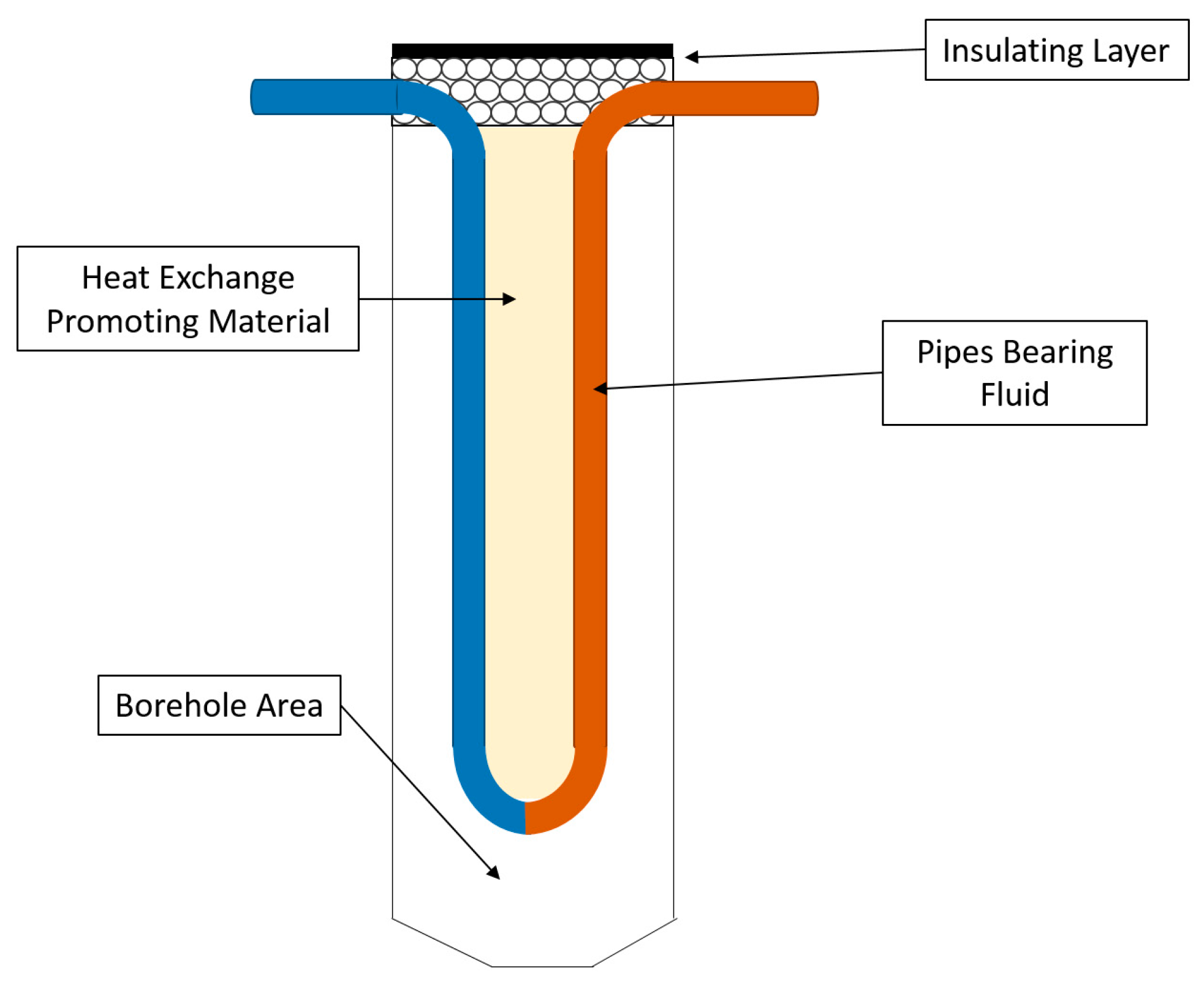
Figure 4.
Concept diagram of solar-coupled GSHP with integrated BTES and diurnal storage [48].
Figure 4.
Concept diagram of solar-coupled GSHP with integrated BTES and diurnal storage [48].
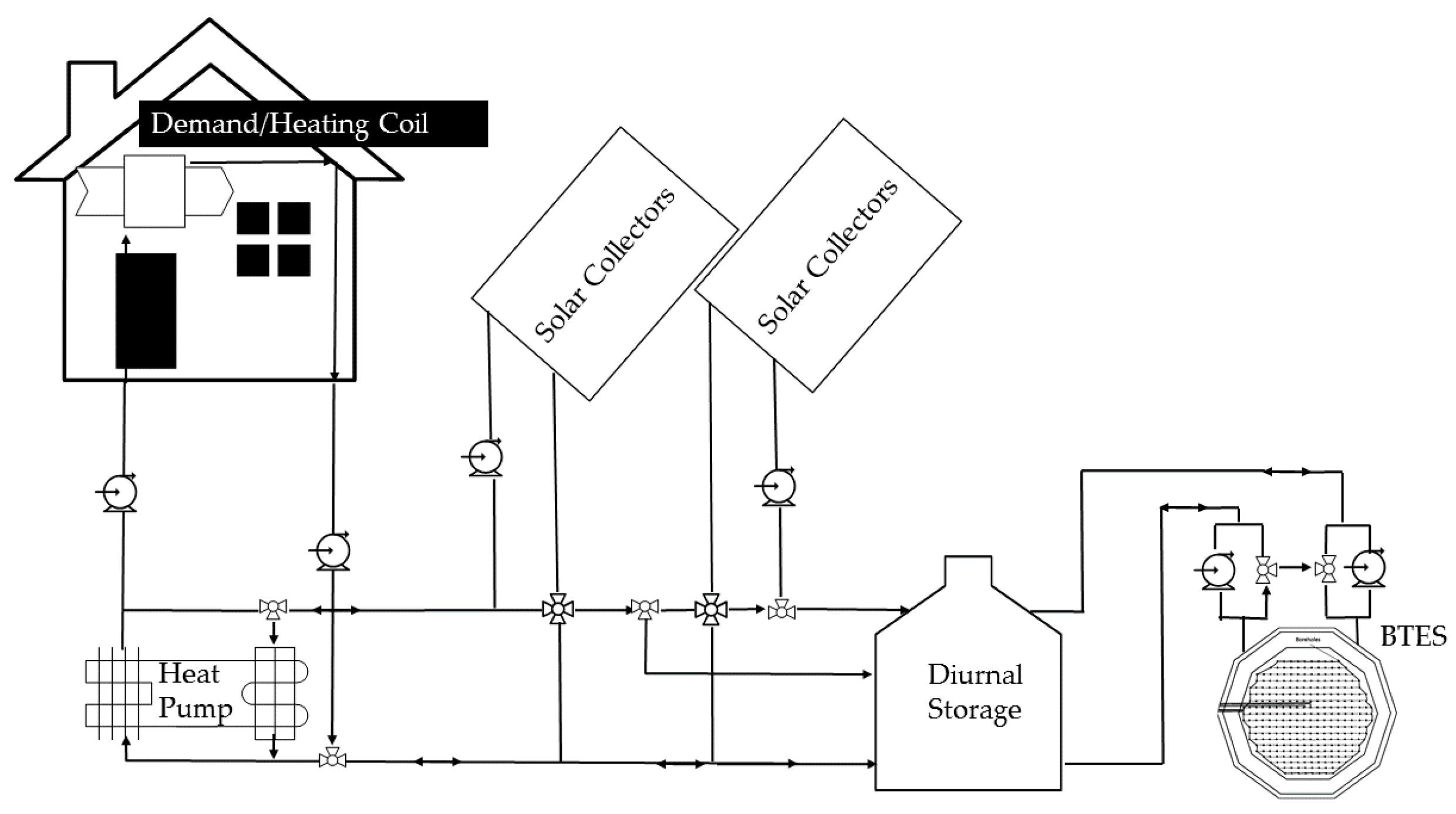
Figure 5.
Design schematic of solar thermal energy system with short and long term storage [43].
Figure 5.
Design schematic of solar thermal energy system with short and long term storage [43].

Figure 6.
Increasing solar collector area and equivalent design storage of BTES.


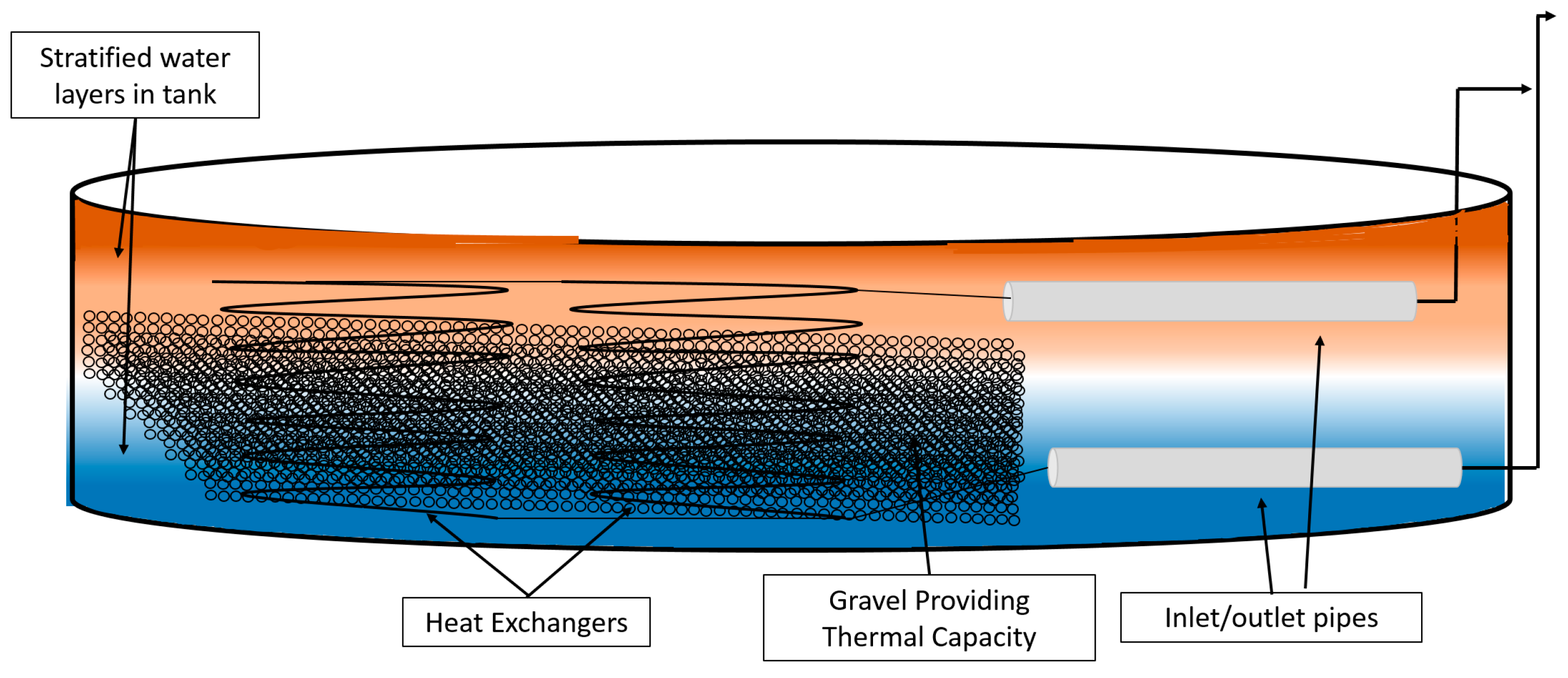
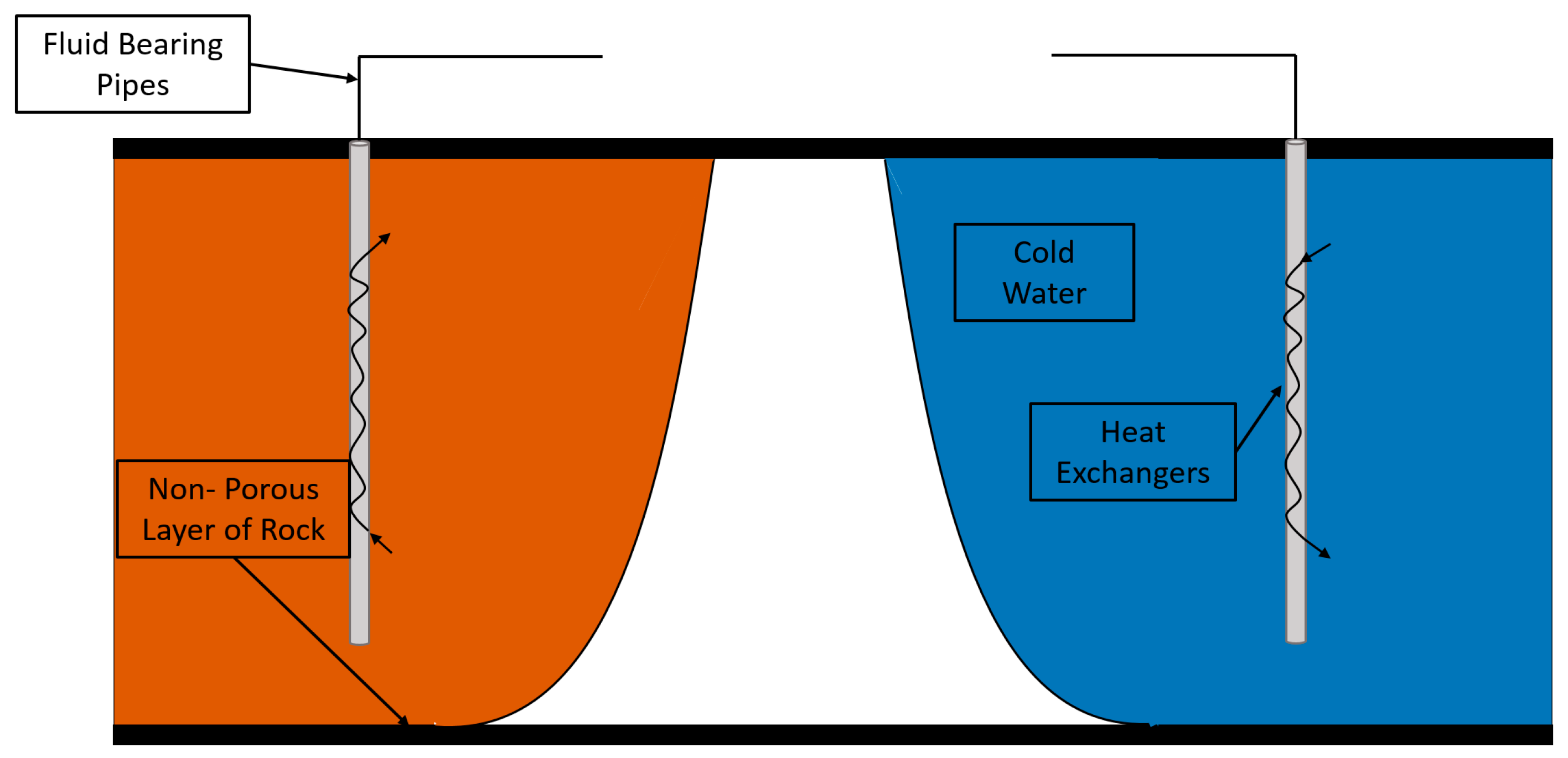
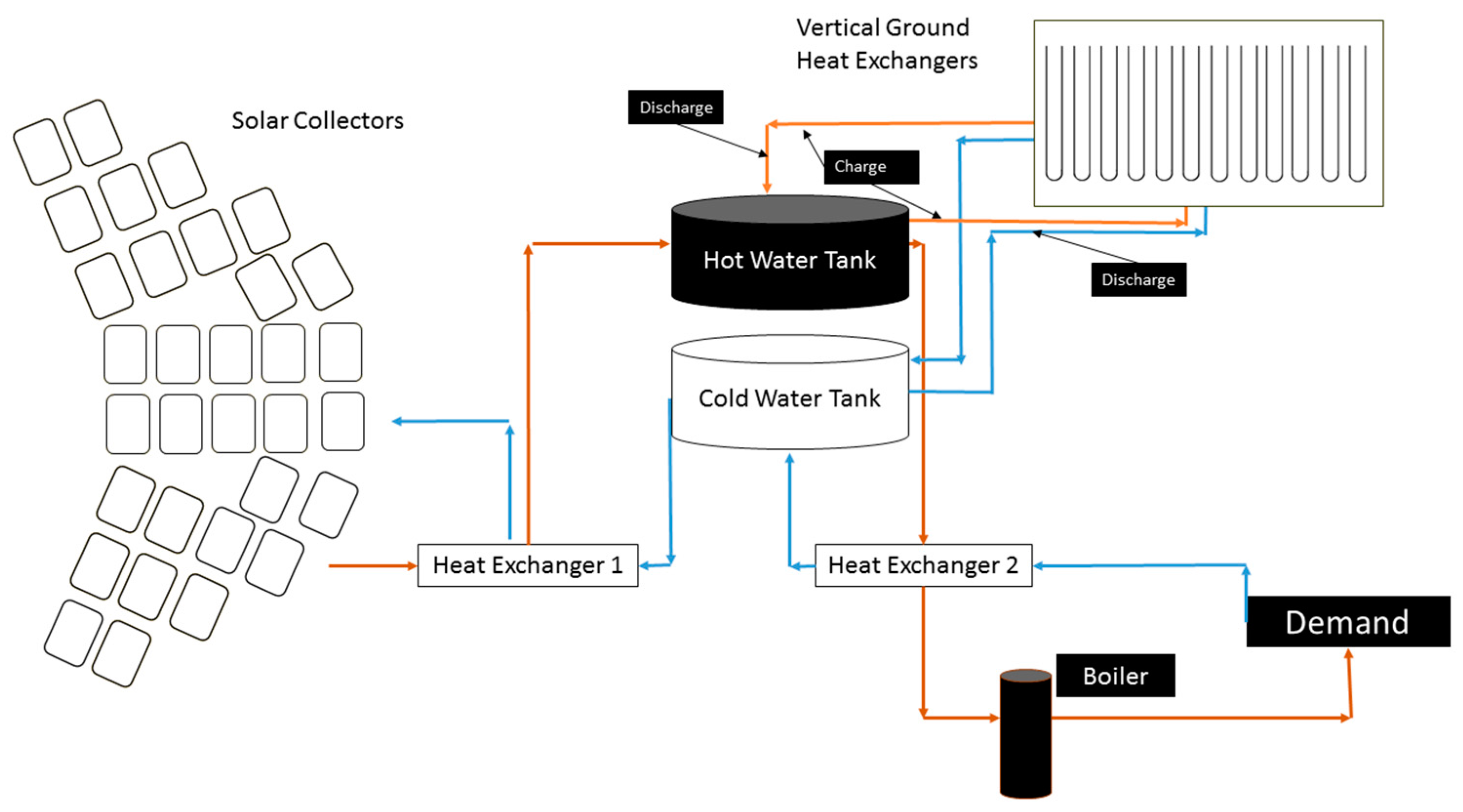
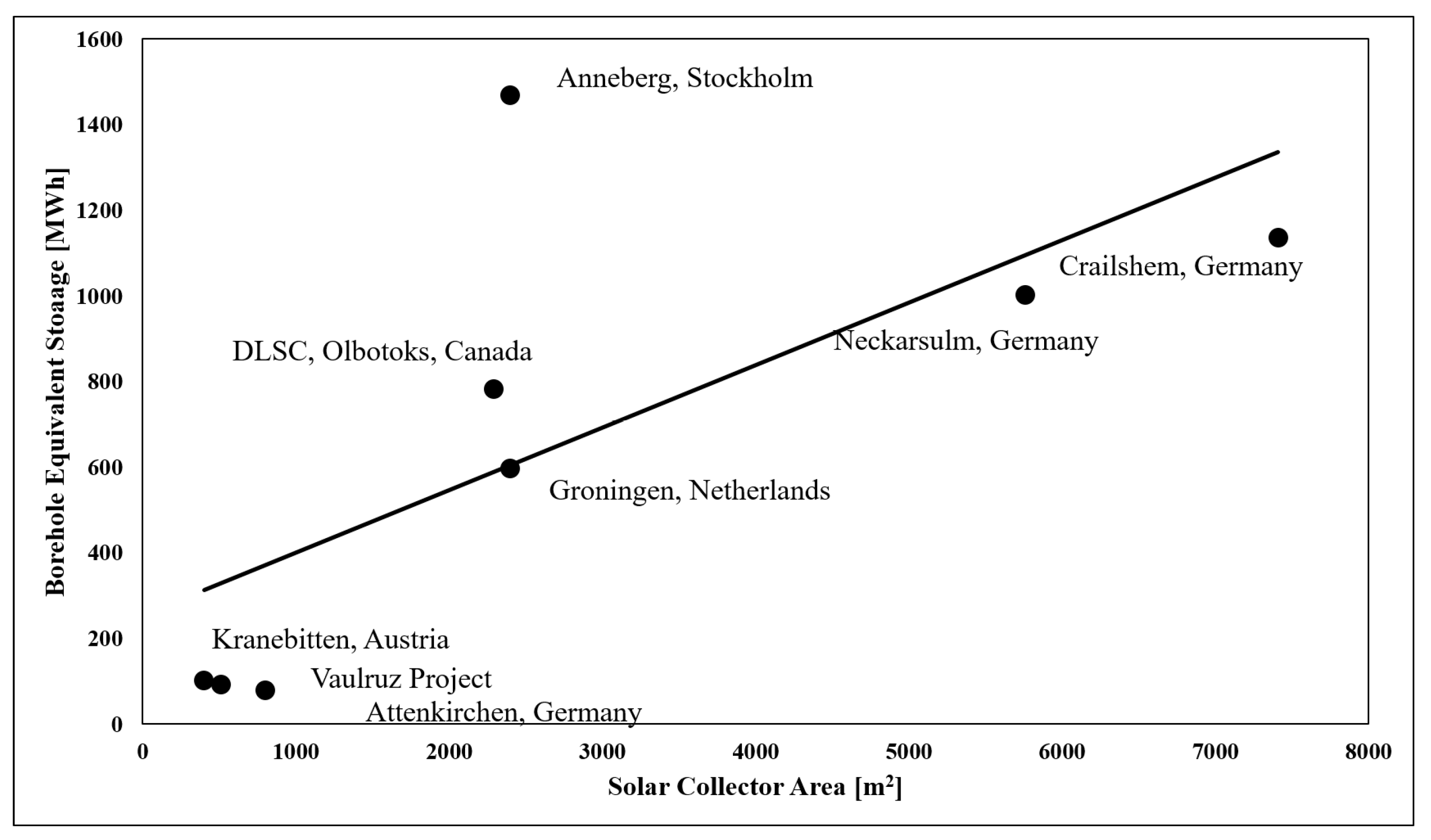
Table 1.
Comparsion of seasonal thermal energy storage.
| Seasonal Storage | Cost (Quantitative) | Geographical Limitations | Energy Recovery | Heating/Cooling Application | Storage Capacity Compared to 1 m3 Water |
|---|---|---|---|---|---|
| HWTES | High due to manufacturing costs | None | High (~90–98%) [41,79] | Heating | 1 m3 |
| GWTES | High due to manufacturing costs | None | Lower than HWTES because of greater thermal conductivity [62] | Heating | 1.5 m3 [55,57] |
| Snow Waste Pit/Ice Pond | Low installation cost (~2–5$/kWh) and operating costs | Regions with high annual snowfall or ponds | Free cooling | Cooling | 0.67–2 m3 [45,51,69] |
| ATES | Low initial drillling and equpment, with high maitenence costs [46,56,62] | Limited to aquifers | Medium (65–95%) [73,76] | Heating and Cooling | 1.5–2.5 m3 [62] |
| BTES | High drilling cost, low maitenence and manufacturing costs, modular construction [41,48,57] | Harder rock may increase drilling costs | Low (~70–90% efficieny) [62] | Heating and Cooling | 2–4 m3 [62] |
Table 2.
Community sized BTES constructions.
| Location | Building(s) | Year Built | Energy Source | No. of Boreholes | Storage Volume [1000 m3] | Estimated Thermal Storage Capacity [MWh] |
|---|---|---|---|---|---|---|
| DLSC in Olbotoks, Canada [43] | 52 Residential Homes | 2007 | Solar Thermal | 144 | 34 | 780 |
| Neckarsulm, Germany [88] | 300 Homes & Shopping Center | 1997 | Soar Thermal | 528 | 63 | 1000 |
| Akreshus University Hospital, Norway [42] | Hospital | 2007 | GSHP | 228 | 300 | N/A |
| Nydalen Business Park Oslo, Norway [85] | Several Large Buildings | 2004 | GSHP | 180 | 1800 | N/A |
| Brædstrup District Heating, Denmark [111] | 1500 households | 2013 | Solar Thermal | 48 | 19 | 616 |
| Crailshem, Germany [48] | School & Gymnasium | 2007 | Solar Thermal | 80 | 39 | 1135 |
| Attenkirchen, Germany [89] | 30 Homes | 2000 | Solar Thermal | 90 | 10 | 77 |
| Anneberg, Stockholm [87] | 50 homes | 2001 | Solar Thermal | 99 | 60 | 1467 |
| UMASS Campus, USA [98] | University Campus | Simulation | Existing Steam Turbines | 6000 | 620 | 37,000 |
| University of Ontario, Canada [112] | Four University Buildings | 2004 | Heating and Cooling GSHP | 370 | 1400 | 9700 |
| Groningen, The Netherlands [113] | 96 residences | 1985 | Solar Thermal | 20 | 23 | 595 |
| Kerava, Finland ** [62] | 44 Flats | 1985 | Solar Thermal | |||
| Vaulruz Project [113] | Maintenance Center | 1982 | Solar Thermal | Horizontal Tubing | 3.5 | 90 |
| Kungsbacka, Sunclay, Sweden [62] | School Building | 1980 | Solar Thermal | N/A | 85 | 86,000 |
| Innsbruck, Kranebitten, Austria [113] | 1200 MWh/year | 1983 | Solar Thermal | Horizontal Tubing | 60 | 100 |
** Information lacking due to study year.
© 2017 by the authors. Licensee MDPI, Basel, Switzerland. This article is an open access article distributed under the terms and conditions of the Creative Commons Attribution (CC BY) license (http://creativecommons.org/licenses/by/4.0/).
Share and Cite
MDPI and ACS Style
Lanahan, M.; Tabares-Velasco, P.C. Seasonal Thermal-Energy Storage: A Critical Review on BTES Systems, Modeling, and System Design for Higher System Efficiency. Energies 2017, 10, 743. https://doi.org/10.3390/en10060743
AMA Style
Lanahan M, Tabares-Velasco PC. Seasonal Thermal-Energy Storage: A Critical Review on BTES Systems, Modeling, and System Design for Higher System Efficiency. Energies. 2017; 10(6):743. https://doi.org/10.3390/en10060743
Chicago/Turabian StyleLanahan, Michael, and Paulo Cesar Tabares-Velasco. 2017. "Seasonal Thermal-Energy Storage: A Critical Review on BTES Systems, Modeling, and System Design for Higher System Efficiency" Energies 10, no. 6: 743. https://doi.org/10.3390/en10060743
Note that from the first issue of 2016, this journal uses article numbers instead of page numbers. See further details here.