
Experimental Study of 3D Movement in Cushioning of Hydraulic Cylinder


Department of Fluid Mechanics, LABSON, Technical University of Catalonia, Colom 7, 08222 Terrassa, Spain
*
Author to whom correspondence should be addressed.
Energies 2017, 10(6), 746; https://doi.org/10.3390/en10060746
Submission received: 26 March 2017
/
Revised: 20 May 2017
/
Accepted: 22 May 2017
/
Published: 25 May 2017
(This article belongs to the Special Issue Energy Efficiency and Controllability of Fluid Power Systems)
Abstract
:A double acting cylinder operation has been fully monitored in its key functional parameters, focused on characterization of end-of-stroke cushioning and starting phases. Being the cylinder performance reliant in the piston constructive geometry, the number and location of piston circumferential grooves is a significant parameter affecting the internal cushioning system performance. An eddy current displacement sensor assembled in the piston allows assessment of piston radial displacement inside the cylinder tube, which is directly related with the studied operating phases. Due to such 3D displacements, the piston becomes as an active and self-adjusting element along the functional cycle of the cylinder. Mechanical joints orientation and operating pressure are also relevant parameters affecting piston radial displacement and, thus, the cushioning and starting performance. Computational Fluid Dynamics (CFD) results confirm the observed functional role of the perimeter grooves; the flow and pressure distributions, where develops a significant radial force, are also in accordance with the registered radial displacement.
1. Introduction
End stroke cushioning of hydraulic cylinders, widely used in mobile machinery and other highly mechanical demanding industrial applications, is required to avoid mechanical shocks against the cylinder ends and, thus, increase the reliability of the element. In industrial applications, a usual solution is applying some external control by means of valves installed in the hydraulic circuit; in mobile machinery, this control configuration and construction is usually difficult and dependent of several mechanical and hydraulic factors [1,2]. On the other hand, for mobile applications an end-stroke internal cushioning device is usually used.
A general definition of cylinder cushioning could be “a system able to decelerate and stop the motion of a cylinder in an intermediate or final position of its stroke to protect from damage the cylinder itself or its surrounding environment” [3].
The steady state operation of a cylinder is simply expressed by:
where PA is the pressure in the piston chamber, Pa the pressure in the rod chamber, A the effective area of the piston and a the effective area of the piston in the rod chamber. Equation (1) is valid for both positive and negative values of the external force F. By supposing that no internal or external leakages take place, the balance of flows (continuity) in the chambers gives the following results.
where v is the piston velocity, QA the flow in the piston chamber and Qa the flow in the rod chamber. Equation (2) is again valid for both directions of motion of the rod: positive velocity when the rod is extending, negative velocity when the rod is retracting. As a direct consequence, the positive or negative sign affects the volumetric flow though the external ports as well. Proper consideration of the value and sign of the external load highlight the role of resistive and overrunning loads.
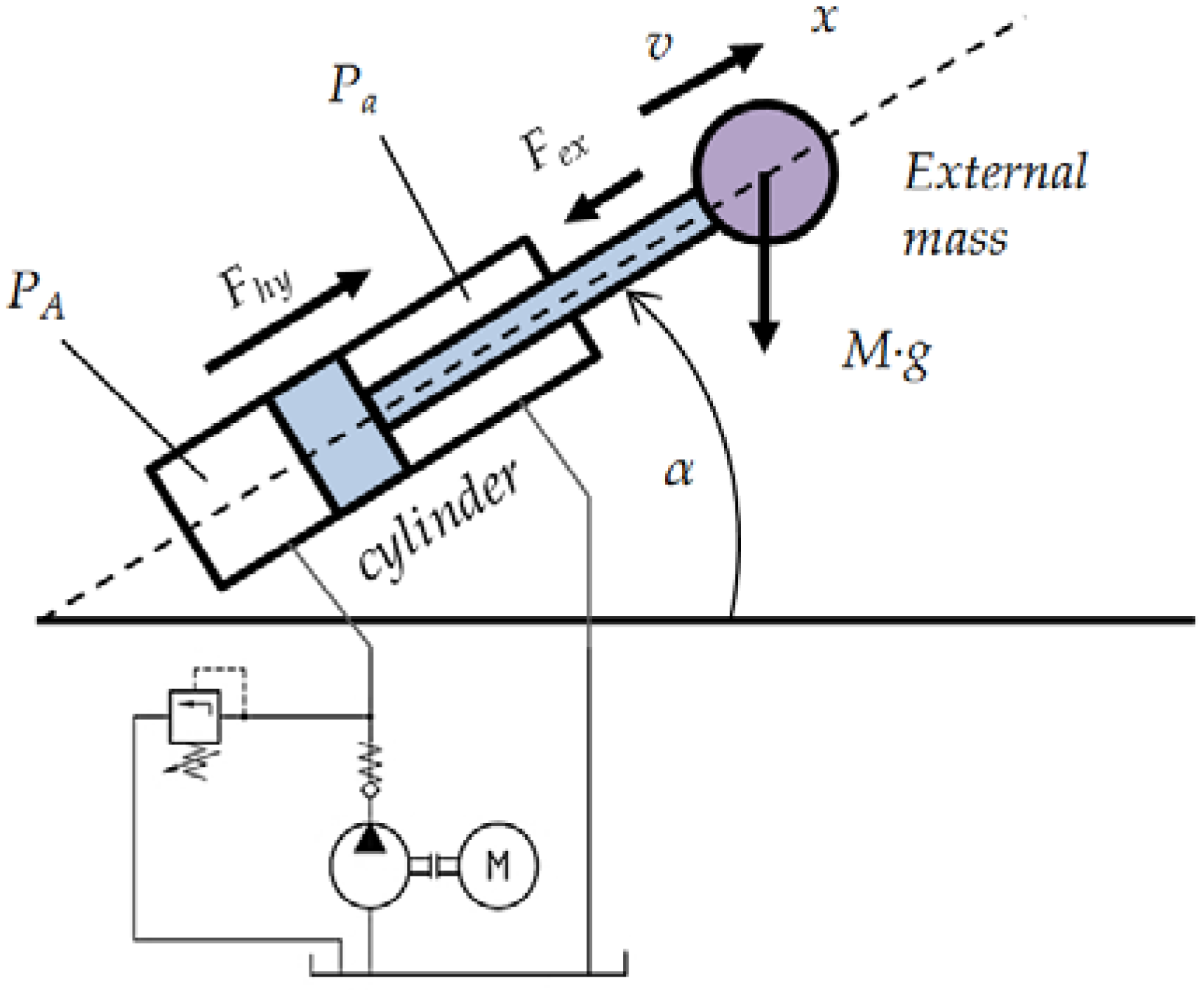
A more general reference scheme for cylinder dynamics can be derived by the situation shown in Figure 1.
This scheme leads to a general equilibrium condition of the forces acting on the rod, expressed in the following form according to their origin:
where Fhy = PA · A − Pa · a (positive if its vector points outside the cylinder) is the hydraulic force generated by the pressure in the cylinder chambers; Ffr is a generic friction force (internal or external to the cylinder), the sign of which is always opposite to the sign of the rod velocity; Fex (positive if its vector points inside) is a generic force acting on the rod due to an external action (resistance); M·g·sin α (positive if its vector points inside) is the component of the mass weight along the rod; M · dv/dt is the inertia force of the mass (positive for a positive acceleration); and x is the position of the rod, measured from the full retraction, which is related with the rod velocity v by the basic rule of mechanics.
When the operating parameters change with time and dynamic conditions, the equations must be changed accordingly. Considering as positive all flow rates entering the chambers, it is possible to write:
where β is the fluid compressibility (bulk modulus) and L the cylinder stroke. In Equation (4), volumes become function of position. A key variable is the velocity perturbation due to a gradient in pressure in the chambers induced by cushioning devices and the dynamic behavior of the relief pressure valve given that the relief valve controls pressure supply.
Various approaches are feasible to study the optimal function of the pressure gradient, but all of them are more or less based on the energy balance during the end stroke, where the initial kinetic energy of the cylinder, and possibly the effect of an external force, must be balanced by the energy dissipation of the cushioning device.
If the cushioning device is based on the dissipative effect induced by a variable restriction, solutions can be obtained analytically once the type of flow (laminar or turbulent) and the area function of the restriction are known. Zanon [4] reported solutions obtained in the case of laminar flow with a linearly varying restriction or turbulent flow with a restriction varying with a quadratic function.
Unfortunately, complex cushioning devices rely on geometries where the flow can be laminar, turbulent or transitional, according to the geometric shape and flow rates involved. Flow conditions in the discharge section may vary along the cushioning stroke and direct reference to a single model is only a rough approximation of the physical reality.
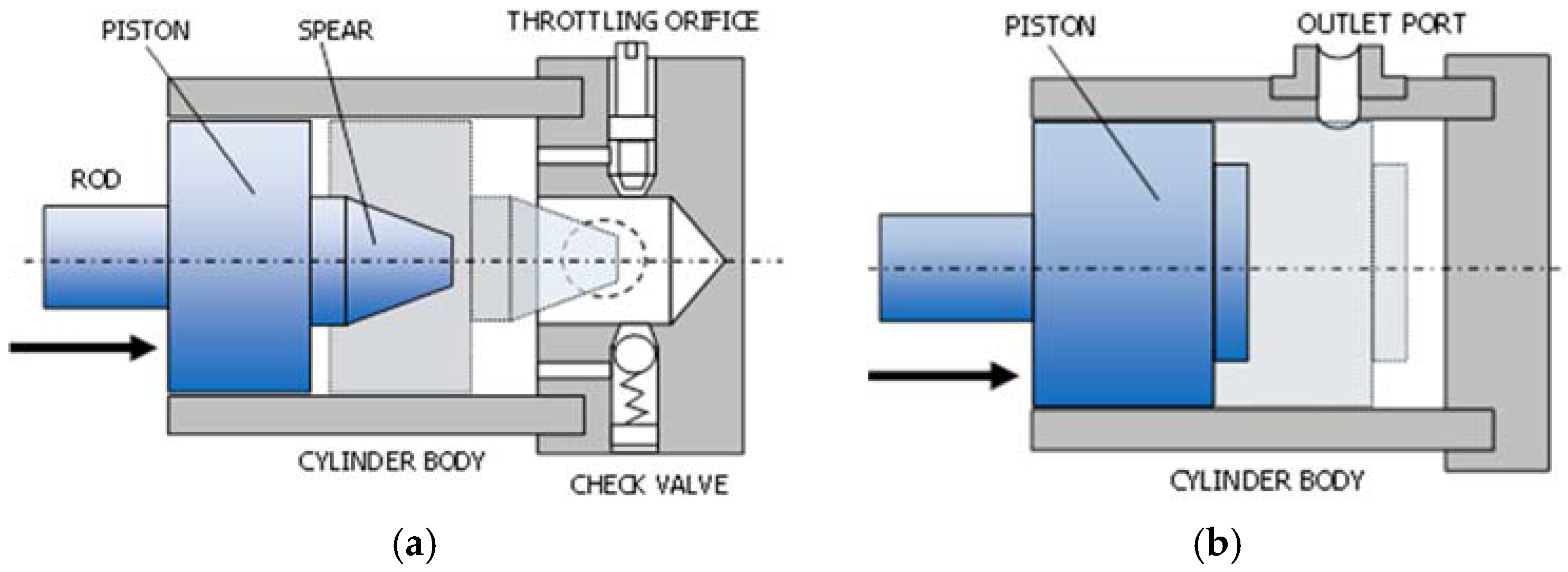
The cushioning devices can be classified into three large groups depending on the geometry [5], as showed in Figure 2:
- Type I: This design includes a spear with a suitable shape or profile which goes into a hole in the cylinder body. Usually the cylinder body also includes a tunable throttling orifice and a check valve, which are adjusted to both directions of the hydraulic actuator motion. Although it is the most usual solution, a complex construction process with a high number of low manufacturing tolerances parts is required [6,7,8].
- Type II: This design is based on the modulation of geometry of the discharge orifice (ports of the cylinder) using the piston body. Thus, once the piston reaches the ports, the oil outlet is restricted, providing to flow high impedance around the interspace between the piston and the internal cylinder wall. The main advantage of this simple manufacturing cushioning design is that it is based in the own elements of the hydraulic cylinder. In order to regulate the performance of the cushioning and allow a rapid starting phase the piston can include constructive elements as peripheral grooves, which manipulate the flow section, or peripheral mobile rings, which actuate as check valve during the cushion and starting phases [9,10,11].
- Type III: This is an additional group that includes any other design [12].
Eventually, to obtain a suitable cushioning performance, with enough velocity reduction and low pressure increments, a proper design is required; several solutions have been successfully modeled and optimized depending on the appliance, all of them based on Type I cushioning system, focused in the design of spears shapes and their tight manufacturing tolerances. Lie et al. [13] developed a model for analyzing the cushioning of a linear actuator with a Type I cushioning system of doubly conical geometry. The authors started with the laminar flow equation through a concentric gap, integrating it in its geometric limits in the different positions of its path, offering an expression that relates the overpressure associated with the cushioning as a function of the position of the actuator. Besides, the effect of the probable eccentricity in the cushioning device was incorporated in the models through a factor of increase on the flow, and in consequence, of decrease on the efficiency of the cushioning. The study also emphasized the simulation of functional parameters such as viscosity, mounting tolerances as well as eccentricity and misalignment, which were at last experimentally uncontrolled and have a well-defined effect on the efficiency of the cushioning system.
Li et al. [14] established a model for analyzing the cushioning of a linear actuator with a Type I cushioning system of conical geometry. The author began from the equation of flow, in this case in turbulent regime, through a concentric gap, integrating it in its geometric limits in the different positions of its path, offering an expression that relates the overpressure associated to the cushioning as a function of the position of the actuator along three successive stages. In this case, the effect on the cushioning pressure in a first stage was incorporated in the simulation when the actuator approaches its limit switch but does not insert the male spear in its female housing, when the radial clearance is not formed but the geometry of the system begins to cause some restriction in the flow. The model considered that the radial clearance was concentric as well as that the cushioning overpressure was constant throughout a phase of the cushioning, both simplifications being of considerable magnitude. Finally, the study incorporated this equation into the dynamic equation of the actuator to perform a simulation of its functional behavior.
Borghi et al. [15] performed a study of mechanical cushioning systems at the end of stroke of hydraulic linear actuators, analyzing various geometries (cylindrical, conical, double conical, etc.) with the objective of establishing a simulation mathematical model, being validated through experimental results. All the studied geometries were Type I.
The models were designed in order to evaluate dynamic parameters characteristic of the cushioning, such as the velocity and pressure of the cylinder chambers, depending on the geometry of the cushioning system. It was established that the cushioning phase of the cylinder, and consequently the dynamics of the cylinder, could be studied only by modeling the behavior of the cushioning chamber. In particular, the deceleration of the cylinder was performed by modulating the geometry of the discharge orifice of the cylinder. Said geometric modulation was characterized essentially by the radial space and the axial length, which modify the passage of the discharge flow through a narrow conduit, considering a laminar flow. A characteristic parameter Kc was established, the hydraulic conductance, which depends only of the geometry of the cushion zone studied. The work introduced a series of interesting dimensional or non-dimensional parameters for the characterization of the quality of the cushioning performance.
Schwartz et al. [16] studied the behavior of an automatic cushioning system based on the insertion of a rod into a housing at the stroke end of the cylinder causing the flow restriction. The mathematical model was validated through a series of experimental tests. A nonlinear model was applied based on the conservation of energy and mass in all elements of the hydraulic circuit as well as the equation of cylinder motion according to Newton's second law. The cushioning devices on the market often have complex geometries, so this work established for the cushioning device the cushioning factor fc, which is determined experimentally. The results indicated that this cushioning factor was not affected by the working conditions of the cylinder (flow, pressure, load, etc.), but this depended exclusively on the geometry of the cushioning device. It should be noted how the work, when modeling the results, took into consideration the effect of friction on the cylinder dynamics as well as the variation in flow pressure due to the inherent error in the relief valves that regulate this functional parameter.
More recently, Lai et al. [17] established three different simulations models (lumped parameter model, integrated simulation model, and Computational Fluid Dynamics (CFD) simulation model) for a Type I cushioning system of a high speed and high flow rate hydraulic actuator. As we could see in other studies, during the hydraulic cylinder cushion, three stages were considered as are local pressure loss, sharp edge throttling, and aperture throttling. As expected, the three models revealed advantages and disadvantages comparing their results with experimental data obtained. Finally, the integrated simulation was chosen for a geometry design optimization study considering its balanced accuracy and calculating time; on the other hand, the CFD model would be mainly helpful for analyzing the evolving flow and pressure fields in cushion chamber. Obtaining the optimal results for a conical design, the diameter of cushion hole, and length of plunger are key parameters to optimize, both dimensions required within tight manufacturing tolerances, as is well known for Type I cushioning systems; the authors stated that an optimal scheme of cushion structure can lower about 50% of the peak pressure and the final velocity.
After the state of art reviewed, entirely focused in type I internal cushioning systems modeling and characterization, it can be stated that most of the models show several simplifications. On the other hand, we can verify that low or null interest is shown in Type II cushioning systems study; the key factors affecting in their performance have not been yet identified and reported.
In this context, this paper starts from the investigation of a specific cushioning device Type II arrangement, which includes the assessment of functional role of the peripheral piston grooves. It tries to highlight some dynamic effects induced by unbalanced radial loads using a novel radial displacement measurement method and a first few hits about numerical and experimental tests.
This paper is organized as follows. Section 1 presents the state of the art and the introduction of the work carried out in this paper. Section 2 details the experimental work by designing, constructing and operating a hydraulic cylinder test bench. Section 3 describes the main results of the investigation: first, regarding the cylinder extension and the main operative parameters measurement; and, second, the piston radial displacement measurement inside the cylinder tube. This section also includes a first CFD numerical test that has helped us confirm the radial movement of the piston. Finally, in Section 4, conclusions about the piston radial displacement as a key parameter in the cylinder performance are discussed.
2. Experimental Method
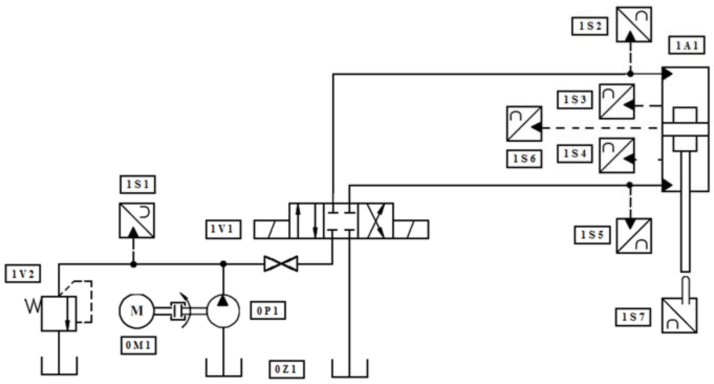
The experimental setup is composed of a hydraulic circuit and monitoring sensors as shown in Figure 3 and Figure 4. Two different assembly positions of hydraulic cylinder have been tested, relative to the fixation axis of the cylinder: first with the perpendicular axis and second with parallel axis. Depending on the assembly position, the eddy current sensor measures the displacement of x or y axis, as detailed in Figure 5. As detailed in Table 1, the hydraulic cylinder is based on a double-acting cylinder (A1) loaded with negligible mass. It is powered by a constant displacement pump (P1) driven by a motor (M1), along with all the necessary instrumentation components for a full system performance monitoring (S1 to S7). The pressure supply is adjusted by a pressure relief valve (V2). The direction of rod cylinder movement is governed by a conventional directional valve (V1). Data recording (axial and radial displacement of the piston and pressures of the hydraulic circuit) are made with National Instruments data acquisition system USB-6343 NI and Labview software (version 2010, National Instruments Corporation, Austin, TX, USA). A sampling rate of 1 KHz has been used.
A double effect hydraulic cylinder [55 × 35 × 365] has been used in the study. It has the inlet/outlet flow ports in the wall of the cylinder tube; as the cylinder extends, the piston covers toward these ports, the exhaust flow is restricted and the cushioning is obtained.
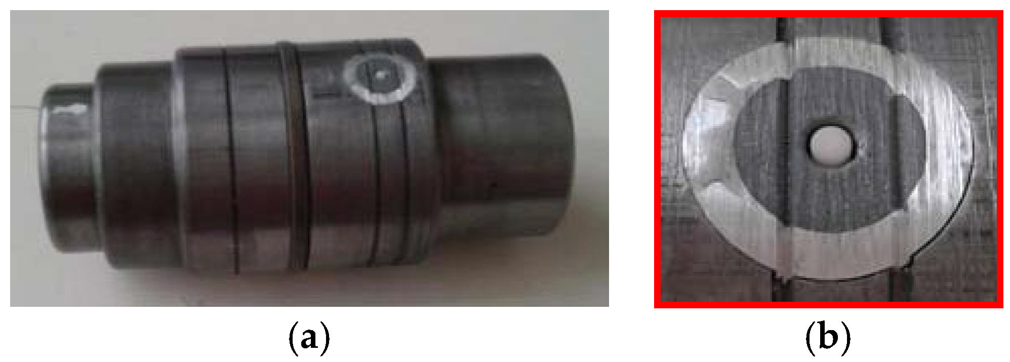
As can be seen in Figure 6, the piston has three machined peripheral grooves: one for rod chamber side and two for piston chamber side. Inside the piston, an eddy current displacement sensor (Micro-Epsilon© series eddyNCDT 3300/3301 model EU05-65, Micro-Epsilon USA, Brownleigh, NC, USA) is assembled. The sensor measures the relative distance between the surface of the piston perimeter, or more exactly, from the measurement point of the sensor, and the interior wall of the cylinder tube. The eddy current measurement principle is applicable to ferromagnetic or non-ferromagnetic electrically conductive materials. “A coil is integrated inside the Sensor housing which is energized by a high-frequency alternating current. The coil’s electromagnetic field induces eddy currents in the conductive measurement object, causing the resulting alternating current resistance of the coil to change. This change of impedance causes an electrical signal which is proportional to the distance of the measurement object to the sensor coil” [18]. The eddy current sensor electromagnetic field penetrates non electrical conductive materials that allow measurements through oil at high measurement rate, with a high sensitivity and precision below a micrometer. The main limitation of this sensor is the low range of measurement, limited to few millimeters; in our case, until 0.5 mm.
We would like to point out that the tests carried out and described in this paper do not include the tests performed with a hydraulic cylinder that moves a significant mass. The mass is a key factor that affects the effectiveness of an internal cushioning device. However, the incorporation of a mass of about 500 kg (represents a very important volume) makes the test very difficult. A light and tabletop support structure has been used in the current experimental study in order to allow rapid configuration changes, as the assembly axis orientation. Besides, a light and hollow rod allows inserting the wiring of the eddy current displacement sensor until the interior of the piston. On the other hand, we considered, a priori, that it could mask the importance of the radial movement that we intend to measure.
3. Results
3.1. Cylinder Extension
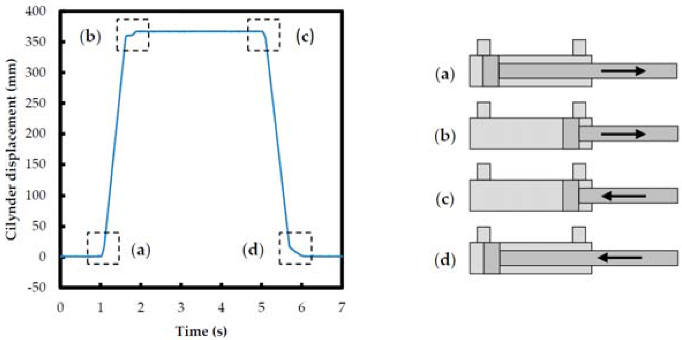
The hydraulic cylinder performs an extension–retraction cycle, as shown in Figure 7 and Figure 8. This cycle has four zones of main interest: starting zones (Figure 7a,c) and end-of-stroke cushioning zones (Figure 7b,d). It can be seen that, in starting zones, the speed of the piston increases quickly and, conversely, during cushioning, there is a sudden reduction of the speed of the cylinder, both manifested in a change of the slope of the curve.
The speed of the cylinder has a direct relation with the flow of the oil along the constructive elements of the cylinder and, more specifically, the exact position of the piston relative to the output ports of the hydraulic fluid.
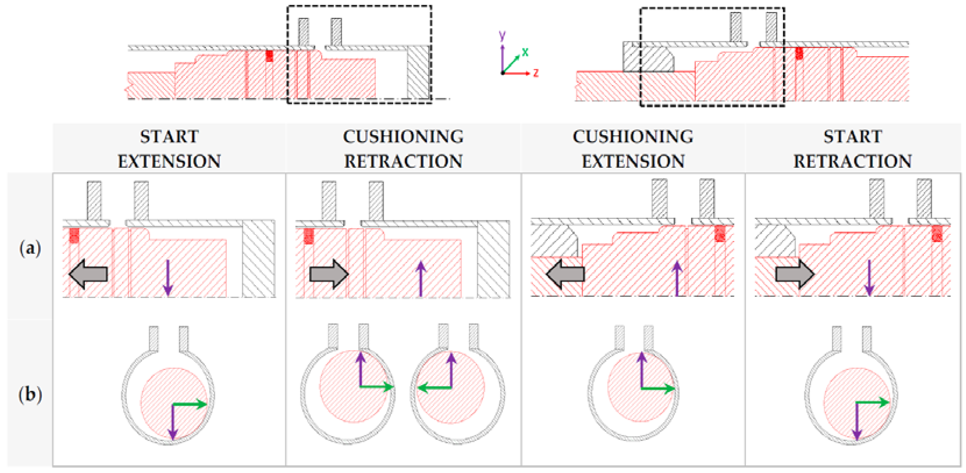
Figure 9 shows the different phases of the cushioning according to the relative position of the piston in relation with the interior of the cylinder chamber and the outlet flow ports, in both end-strokes. The illustration remarks how, while the piston advances until the end of its stroke, the outlet flow port is gradually closed, producing the registered speed reduction.
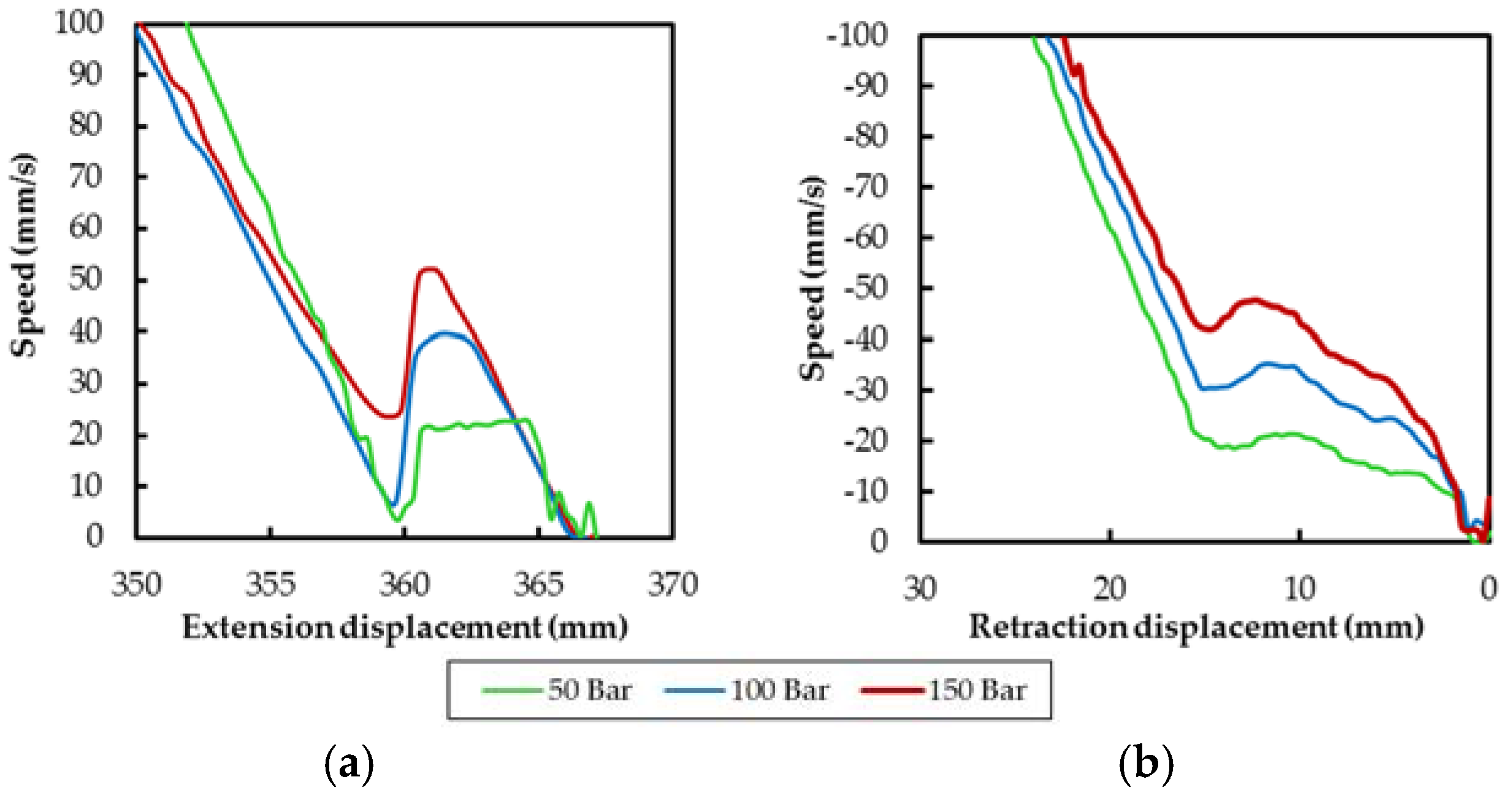
Most of the speed decrease is produced during Phase 1: start of cushioning where the outlet port is gradually closed. In the retraction, cushioning this Phase 1 takes place during the last 25 to 16 mm of stroke; in extension, cushioning is done at 17 to 10 mm.
After that, during Phase 2, the oil flow is restricted only around the small radial interspace between the piston and the cylinder chamber. Consequently, during the last millimeters of the stroke, the speed is kept in a very low range until reach the end of stroke of the cylinder; only small increments and reductions in the speed are registered. Properly speaking, the cushioning is produced during Phases 1 and 2 as consequence of geometry discharge orifice modulation and dynamic behavior of the relief valve. This essentially reduces the approximation of the piston at low speed until its end of stroke.
More precisely, during the cushioning Phases 3 and 4, the shape of the speed variation is highly affected by the number and location of the radial grooves of the piston. During the extraction end stroke the speed reaches almost a zero value when the flow is nearly obstructed, Phase 2: end of cushioning, and it shows up a small increase only when the radial groove reach the outlet port, during Phase 3: Groove. The presence of two grooves in the piston chamber side of the piston, which reduces the duration of Phase 2 and increases the presence of Phases 3 and 4, produces a more gradual variation of the speed at the retraction end stroke cushioning.
Figure 10 shows the cushioning speed from Phase 2 for the extraction and retraction movement directions in relation with the studied operation settings. The effect of the groove configurations in the shape of the curves, as stated above, can be noted in the following enlarged curves.
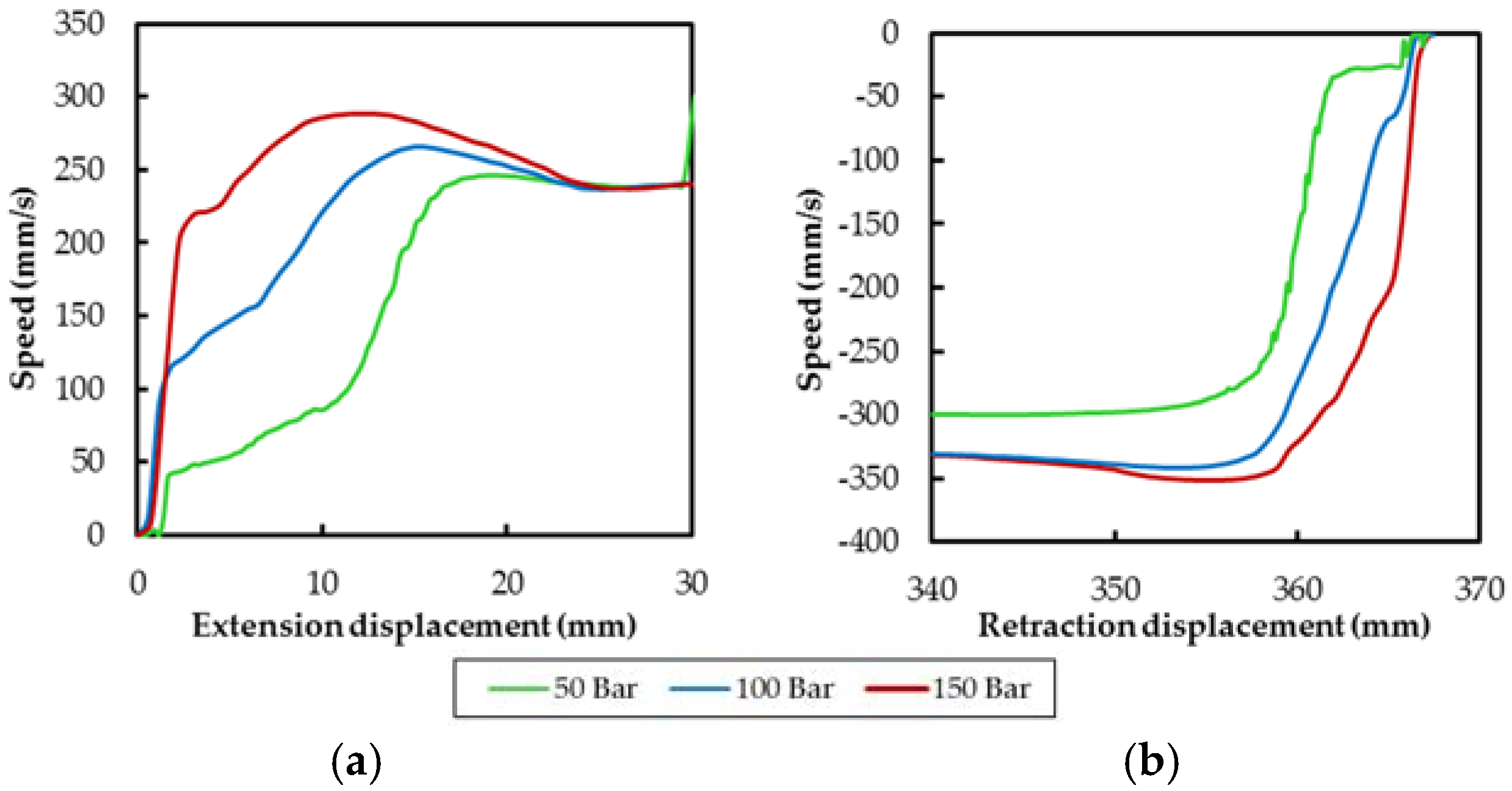
It can be seen in Figure 11 that there are differences in the shape of the speed curves between the cushioning and starting phases. The first difference noted is that during the first 3 mm of starting stroke, there is a sudden increase of speed. This initial speed gain is highly dependent of the pressure supply (sensor S1 in Figure 3). At 150 bar pressure supply, for example, it initially reached almost 100% of the nominal extension speed. Besides, in opposition with the cushioning phase, the shape of the speed curve during starting phase is not affected by the number of the grooves. Given that the constructive elements of the cylinder are not modified with the direction of the motion, it can be concluded that the fluid-dynamics are produced in different circumstances during the cushioning than the starting operating phases.
3.2. Assembly Configuration
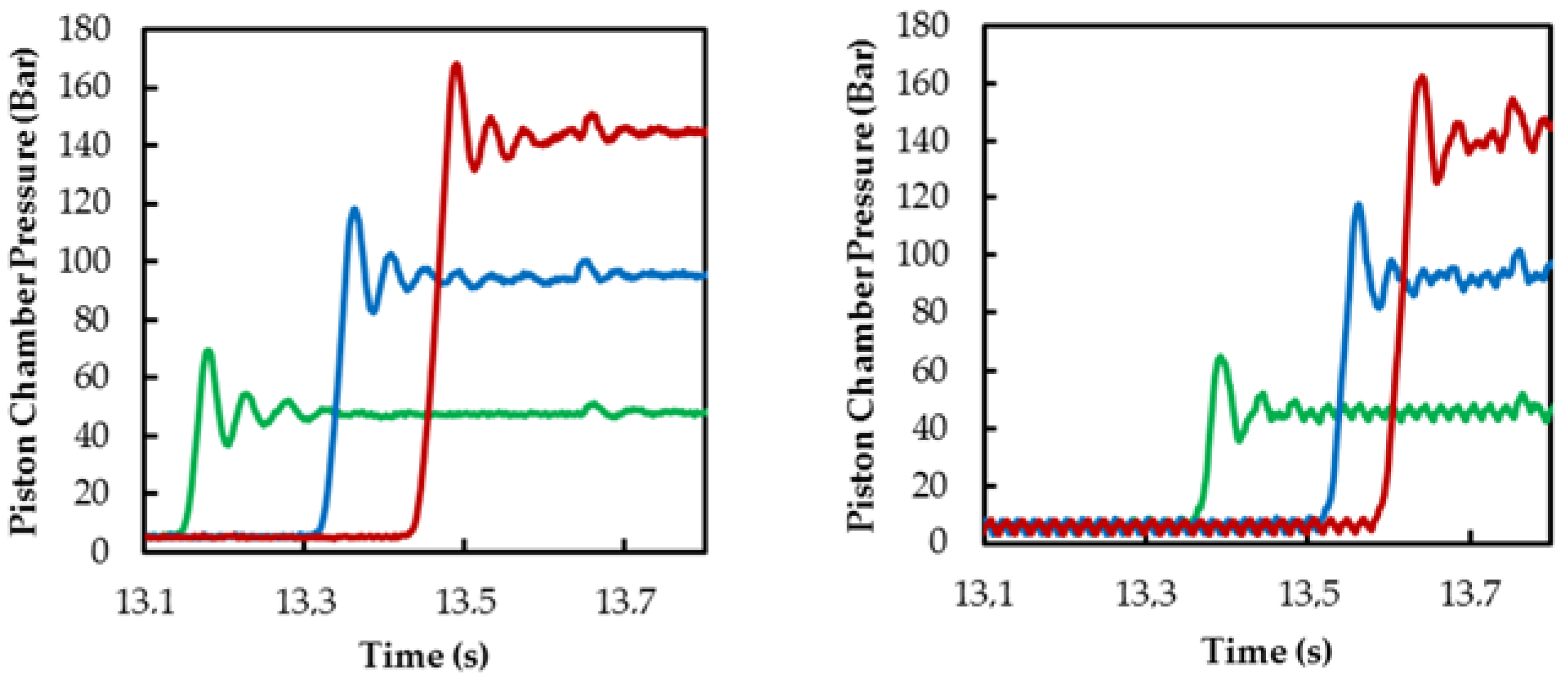
As stated in Figure 7, there are four characteristic starting and cushioning zones in which the interaction of the piston with the hydraulic oil ports is observed. The duration of these phases can be determined from the changes of speed along the cylinder stroke, as shown in Figure 12 and summarized in Figure 13. Starting and extension duration evolves differently depending on the mounting configuration of the cylinder fixation axis, with parallel or perpendicular assembly; it is significantly different at the end of piston travel and a lesser degree with the cylinder in its retracted position. Given that the interior constructive elements of the cylinder are not modified with cylinder clamping shafts assembly, it can be concluded that the fluid-dynamics would be produced in different circumstances depending on the assembly configuration.
The differences of performance between parallel and perpendicular axis of assembly, registered in Figure 13 (cushioning duration and pressure), are not apparently explained as changes in the operating pressure, as shown in Figure 14 (pressure and time). Further explanation of this phenomenon will be presented in the next sections.
3.3. Radial Displacement
As explained, significant differences of functional performance in the cylinder have been registered in cushioning and starting phases as well as with the fixation axis assembly orientation. Thus, considering that the structural elements are not modified depending on the sense of motion or assembly position, it is suspected that the internal fluid-dynamics could be affected by the position of the piston inside the cylinder.
The installation of an eddy current sensor inside the piston of the hydraulic cylinder allows the measurement of the relative distance between the outer surface of the piston, or more precisely from the measurement surface of the sensor, and the inner wall of the body of the hydraulic cylinder. Its measurement along the cylinder stroke can be registered and its progression assessed throughout the various stages of its functional cycle. Depending on the mounting axis orientation, the sensor records the distance in two different planes of orientation in regard to the hydraulic ports (Figure 5).
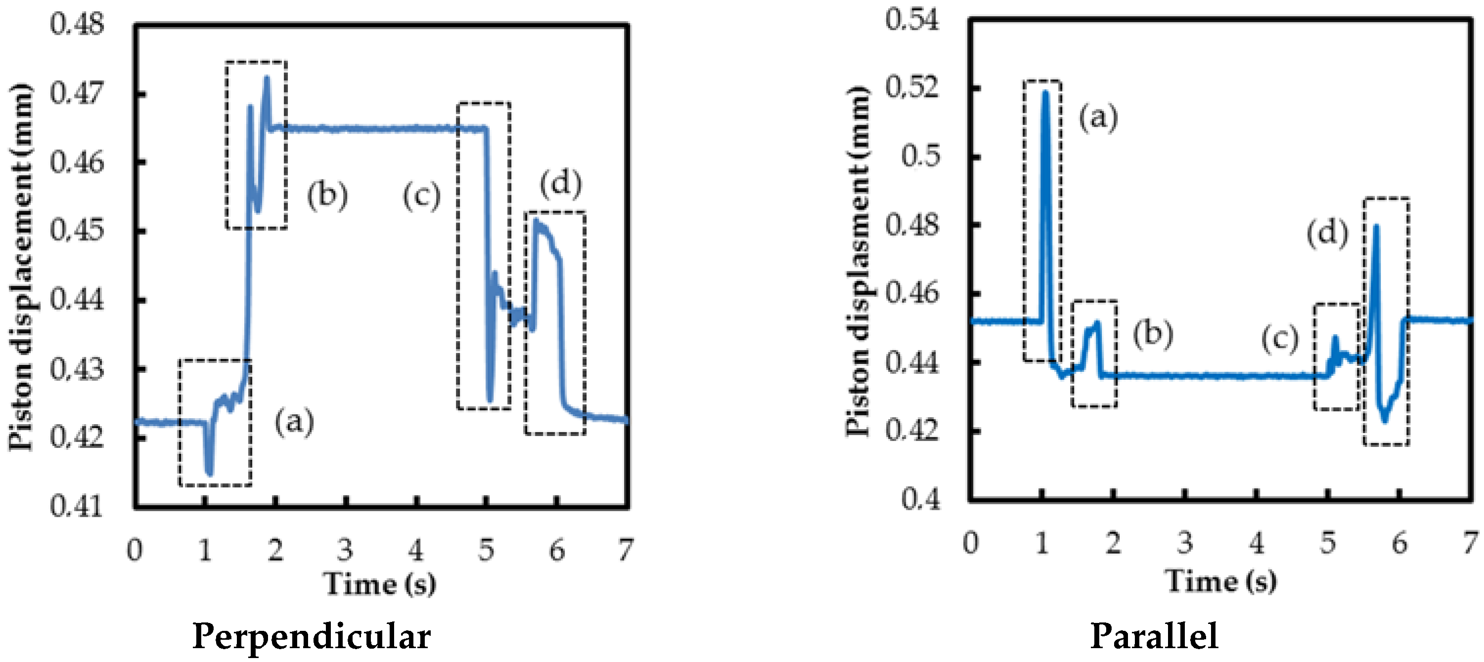
As presented in Figure 15 for a full extension and retraction cycle, the recorded distance shows an actual evolution throughout the operational cycle of the cylinder. The distance between the sensor and the cylinder inner surface (y axis of Figure 5) differs about 43 µm between the fully extended and retracted position for parallel mounting axes; this space is reduced to 16 µm for parallel fixing axis (x axis of Figure 5). Misalignments between rod and cylinder tube fixing axes, according to the longitudinal displacement axis seem to be a probable cause. This misalignment is judged unavoidable for the fixation method used, being typical of usual assembly tolerances or by wear of guide rings. Initial imperfection due to misalignment in the interface between cylinder tube and piston-rod creates an imperfection angle between piston-rod and cylinder tube centroid axis, which evolves depending on the piston stroke [19].
The most important matter is that, although it would be expected that in the movement of extension and retraction of the cylinder the measured distance would evolve from one level to another approximately linear, a number of important deviations are observed in that awaited linearity. They are perfectly in coincidence with the starting (Figure 15a,c) and cushioning phases (Figure 15b,d) along the movement of the cylinder.
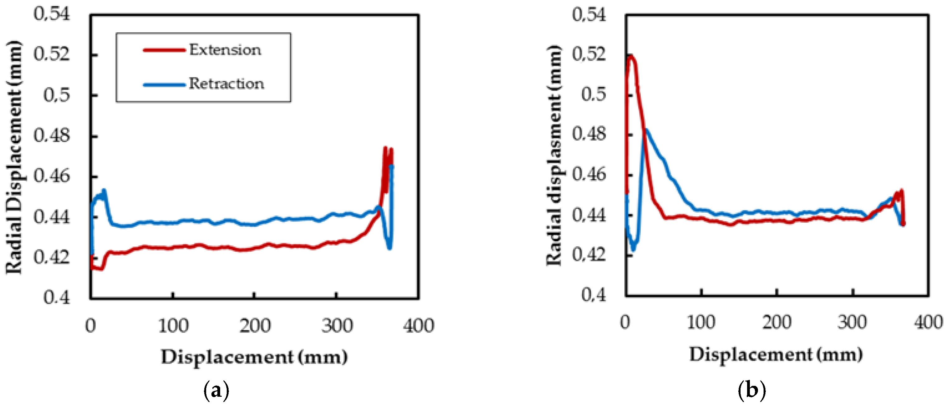
On the other hand, it has also been established that the relative distance between the piston and the cylinder is different during the travel of the piston depending on the direction of cylinder stroke, presumably by a fluid-dynamic effect, as can be seen in Figure 16.
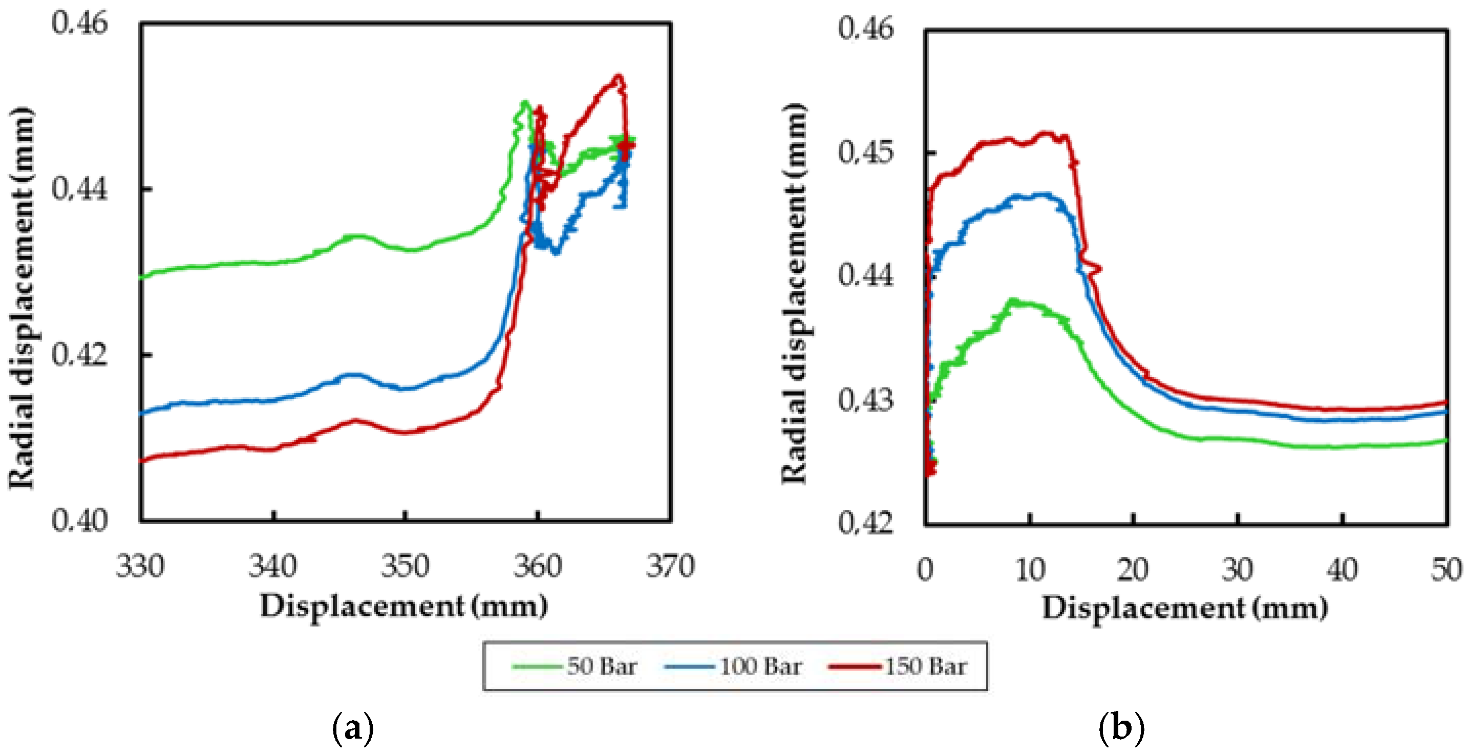
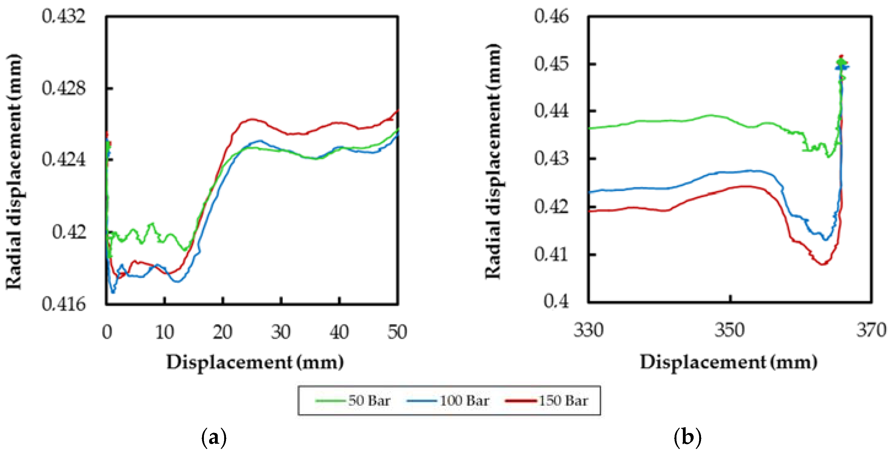
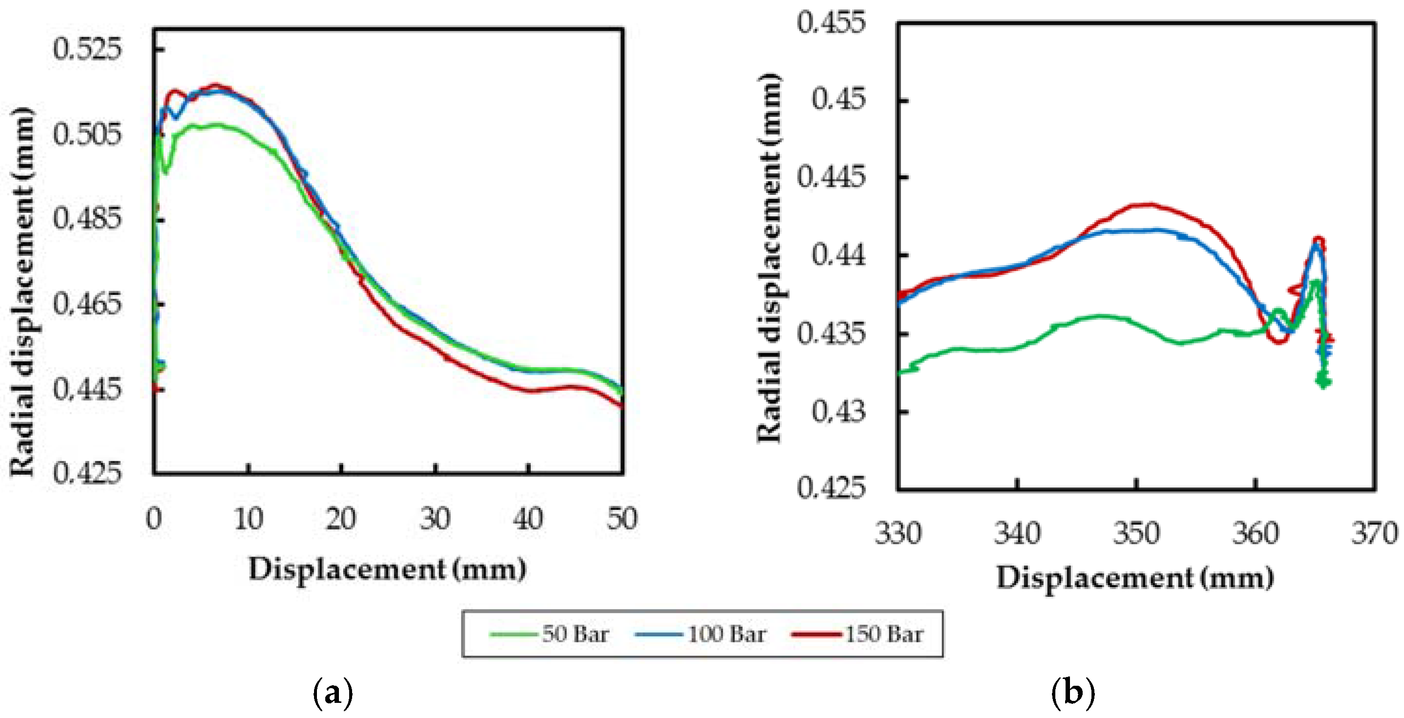
More in detail, Figure 17, Figure 18, Figure 19 and Figure 20 show the piston radial displacement during the different operating phases for the studied supply pressures and assembly configurations. Parallel and perpendicular assemblies represent the radial y and x axis displacement as detailed in Figure 5. Thus, significant effect of the pressure supply over the y axis piston radial displacement during the cushioning and starting phases is observed. On the contrary, the pressure has no an evident effect in the x axis piston radial displacement
In summary, the recorded values of the eddy current sensor demonstrates the movement of the piston inside the cylinder during the cushioning and starting phases, which can be explained mainly from a fluid-dynamic reasoning.
Figure 21 summarizes in a symbolic way the observed direction of the piston displacement in the different functional phases of the hydraulic cylinder, obtained depending on the orientation of the fixation axis. They were measured in different assembly configurations and the differences observed in Figure 13, which highlight that the movements represented in the x and y axes occur not strictly simultaneous as they have represented and they may be different in direction and magnitude depending on the configuration of cylinder mounting.
The figure shows how the piston is able to adapt its position in y axis within the interior of the cylinder body depending on the pressure and flow conditions, naturally favoring cushioning or starting functions. Firstly, at the starting phases the piston move in the direction of flow due to the inlet pressure, helping fluid inlet. It would be why, therefore, it is not observed the effect of the grooves in the cylinder displacement curves; so, the displacement of the piston makes irrelevant the presence of the grooves during starting. On the other hand, during cushioning, the piston is pushed towards the outlet port, thus achieving greater fluid flow restriction. In this case, the pressure in the cushioning chamber increases suddenly in Phases 1 and 2 while the flow is restricted and, therefore, the pressure in the output port becomes almost zero; this pressure differential would displace the piston in the registered direction. Both behaviors would explain how the startup phase is, in all cases studied, significantly faster than cushioning phases.
3.4. Preliminar CFD Numerical Tests
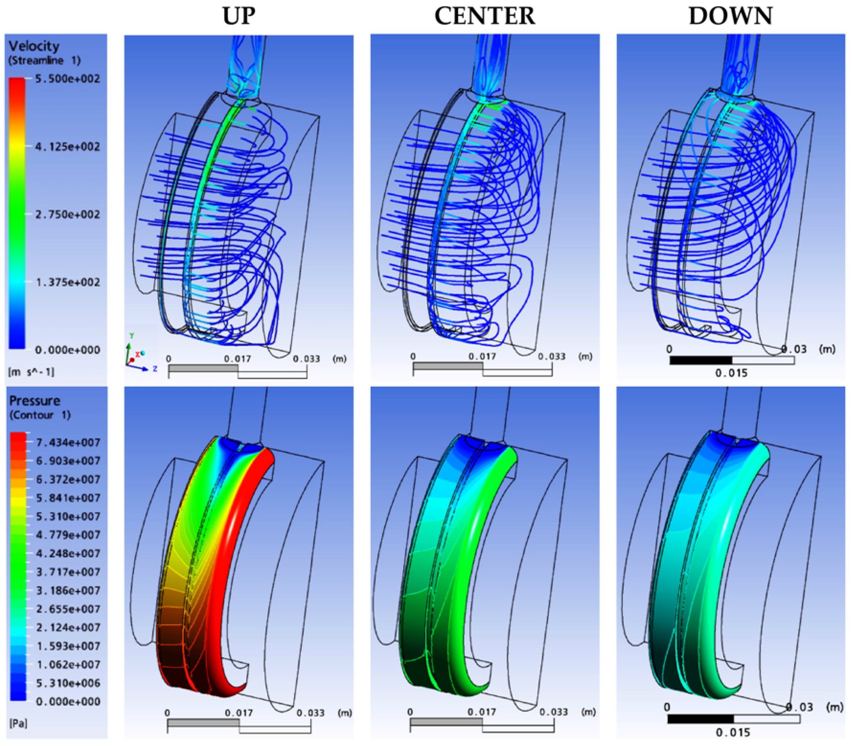
The preliminary results obtained from CFD simulation of the cushioning are summarized in Figure 22. The model used in CFD analysis is the part of the space inside the cylinder filled with the oil. It is possible to build it with 3D CAD tools starting from the draw, anyway, following a logical approach, the first step is the definition of a 3D solid model of the cylinder based on the draw, then the fluid domain is got through a Boolean operation. In this case, three models were built: in the center, and up and down the cylinder axis with an eccentricity of 53 micron. Two simplifications are introduced in order to reduce the computational weight of the model: the connection inside the piston and part of the gap behind the second groove (the smallest) are neglected. This connection is useless because relevant phenomena are in the gap between piston and cylinder. In addition, the last part of the gap could be cut from the model because behind it there is a seal and no flux of oil. An eccentricity of 53 micron is chosen because it is the maximum possible according to computational resources. In this way, there is a gap of 15 micron in the thinner part, and 121 micron in the thicker part. The number of mesh elements, taking the centered piston as reference, grows faster in the part with the thin gap compared to the reduction in the thicker meatus. Thus, total number of elements increases with the eccentricity.
Many meshes were built and used, each one with different characteristics, because different results in analysis were achieved in consequence of the use of distinct turbulence models, mainly the k-epsilon and the BSL Reynolds stress, which offered finally the best results. The number of elements in the boundary layer and thickness of the first element were relevant for the solution and there were also differences using the same mesh with different turbulent models. The finally selected meshes for each position are listed in Table 2, followed by their main characteristics. Differences are present in the number of element in the gap between piston and cylinder and in the construction of first element at the wall.
After obtaining all meshes, analyses were performed with many constant parameters. Oil is always Mobil DTE 46 Excel Series (ExxonMobil México S.A., México D.F., México) Piston position is at 13 mm from the start of the stroke, at the complete discharge closure. Variations are only in kind of mesh, eccentricity (53 micron up, down or nothing) and model for the state of flow (laminar, k-epsilon, k-omega, BSL Reynolds stress). K-epsilon and BSL Reynolds stress were mainly used, offering the BSL Reynolds model the more suitable results.
The convergence criteria used is to get to a target average normal residual of 10−4. We are interested in the medium description of the flow but not in the details around the discharge. This kind of residual considers the average error in the domain in comparison with the true solution, normalized with the width range of the variable. Then, the range of variability of pressure and velocity in domain is of two orders of magnitude, therefore a relative error of 10−4 implies a precision of the solution about of 1%, so very close to the real one. Sometimes, the relative error is a bit small to obtain a better convergence of results. In addition, relaxation factors of iterations are sometimes changed (default = 1), in consequence of very high pressure peaks at run start.
Looking at Figure 22, differences about pressure values and distribution are immediately visible and a greater value of radial forces is expected in position with piston up. It is also possible to see that oil flows mainly in the first groove in up position, while an important part of it goes directly to discharge port with piston down; along the groove the Reynolds number is in all cases over 5000, being so in transition to turbulence flow regime. This fact is visible also in pressure field because in up position a low blue pressure area is around the first groove and pressure around discharge port does not change as quickly as down position. This means that oil flows in the first groove where bigger pressure losses are visible. All these considerations lead to the conclusion that, despite the constant area of the gap between piston and cylinder, the behavior of the oil changes as a consequence of the 3D movement: when piston is up, it see a large meatus under the piston, so it enters grooves and flows towards the discharge port. It means that a long travel is necessary for going to the outlet. When piston is down, a large gap is instead near the hole. Oil finds less resistances and it has less pressure losses in this way. Pay attention to the oil speed in the straight travel between piston chamber and outlet. In up position velocity is about five times more compared to down position, but the gap width is about eight times less, so the flow rate is less.
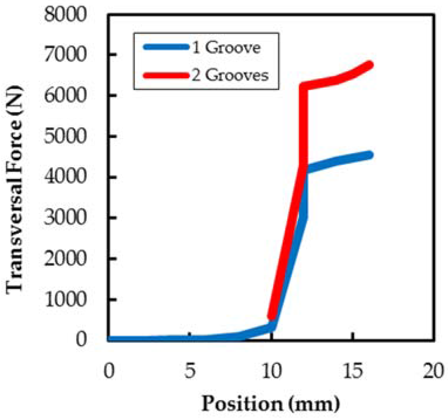
It should be noted that the piston grooves have two significantly different roles, depending on the operating phases of the cylinder. During the main course of the cylinder, the grooves would minimize the eccentricity of the piston inside the cylinder tube, reducing the radial acting force derived of the irregular pressure distributions caused by the unavoidable imperfections in the construction of the cylinder; this effect is well studied and applied in order to avoid the locking during the movement of valve spools, where the grooves have a perimeter pressure balance function during the axial flow along the spool [20]. On the other hand, as presented in Figure 9 and supported by the CFD results in Figure 22, the perimeter piston grooves, as part of the internal cushioning system, have the main function of modulate the output flow during the last phases of the cushioning thanks to their additional perimeter flow section. CFD simulations show how the groove receives the hydraulic flow from the interspace between the piston and the cylinder tube by a pronounced pressure gradient directed to the output cylinder port. Besides, due to the flow to the outlet ports a transversal force is generated in the later steps of the cushioning, significantly affected by the number of piston grooves as shown in Figure 23, which support that the piston radial displacements observed in the experimental study have significant role in the cushioning performance.
In relation to x axis displacement, such a definite behavior is not observed. Local differences in pressure and flow around the piston, probably caused by asymmetries, as small dimensional differences within the assembly or manufacture tolerances, distribution of weights or wear of certain constructive components, could be the source of such displacement differences. Although it is not the objective of this paper, there is interest in further study of this behavior in the future.
4. Conclusions
The experimental results show significant differences of functional performance in the Type II cylinder registered in cushioning and the starting phases. In addition, differences of performance between parallel and perpendicular fixation axis assembly orientation are detected. Because the internal constructive elements of the cylinder are not modified depending on these operating conditions, it is suspected that the internal fluid-dynamics could be affected by the position of the piston inside the cylinder.
The recorded values of the eddy current displacement sensor shows the piston undergoes a sequence of radial movements inside the cylinder tube associated with the different starting and cushioning operating phases, which can be explained mainly from a fluid-dynamic reasoning.
Thus, due to the existence of revealed 3D piston displacement, in Type II internal cushioning systems the piston becomes an active and self-adjusting element along the functional cycle of the cylinder.
A first approach to the CFD simulation of a Type II cushioning system explains the fundamental role of the grooves in the cushioning performance; the number and location of grooves actuate in the regulation of the flow to the outlet port, where an increasing pressure gradient is registered with an increasing piston eccentricity. Besides, the generated pressure gradient produces a significant radial force increasing with the number of grooves, in coherence with the radial piston displacement experimentally registered.
The knowledge of this radial displacement and the functional role of the perimeter grooves starts new ways in the design optimization of the cylinder geometry during the important phases of starting and cushioning, as can be the consideration of interesting lower manufacturing and assembly tolerances, the considerable role of the axis orientations assembly or the importance of the number and location of peripheral grooves. It is noteworthy that the optimization of the listed design key factors, as the characterization of other as the operating load, not taken in consideration yet, are areas of great interest in future research.
In addition, the two assembly axis orientations allowed detecting a possible effect of the asymmetries in horizontal movement of the piston, which is out of the scope of this paper but of substantial interest to be also studied.
Acknowledgments
We thank Pedro Roquet and Juan Jose Fernandez from Roquet Group and Pedro Roquet S.A. who provided important hydraulic devices used in the research. We would also like to show our gratitude to the Dead Roberto Paoluzzi from CNR-Imamoter for sharing his pearls of wisdom with us during the course of this research.
Author Contributions
The investigation was led and supervised by Esteban Codina and Xavier Freire. Experimental works, data processing and illustrations were completed by Antonio Algar and Xavier Freire. The manuscript was finalized by Antonio Algar, Esteban Codina and Xavier Freire.
Conflicts of Interest
The authors declare no conflict of interest.
References
- Virvalo, T. On the damping of a hydraulic cylinder drive. In Proceedings of the Sixth Scandinavian International Conference on Fluid Power, (SICFP’99), Tampere, Finland, 26–28 May 1999; Tampere University of Technology: Tampere, Finland, 1999; pp. 750–770. [Google Scholar]
- Das, J.; Mishra, S.K.; Saha, R.; Mookherjee, S.; Sanyal, D. Actuation dynamic modeling and characterization of an electrohydraulic system. Proc. Inst. Mech. Eng. Part I J. Syst. Control Eng. 2016, 230, 537–550. [Google Scholar] [CrossRef]
- Green, W.L. Cushioning for hydraulic cylinders. Hydraul. Pneum. 1968, 21, 100–104. [Google Scholar]
- Zanon, P. Cushioning Systems Methods for Oil and Hydraulic Servoactuators. Bachelor’s Thesis, Mechanical Engineering, University of Modena/Reggio E., Modena, Italy, 2001. [Google Scholar]
- Imamoter. New Design and Manufacturing Processes for High Pressure Fluid Power; Imamoter: Ferrara, Italy, 2004. [Google Scholar]
- The Flick-Reedy Co. Improvements in or Relating to a Cushioning Adjustment for a Piston and Cylinder Device. GB Patent Application No. 805,929, 17 December 1958. [Google Scholar]
- Conolly, P.W. Hydraulic Cylinder with Cushioned Stroke. U.S. Patent 3,559,535, 2 February 1971. [Google Scholar]
- Parker-Hannifin Co. Cushioning Means for Hydraulic Cylinder. U.S. Patent 3,964,370, 22 June 1976. [Google Scholar]
- Homuth, K.C. Single Directional Sealing Piston Ring. U.S. Patent 4,207,800, 17 June 1980. [Google Scholar]
- Callies, R.E. Cushion Hydraulic Cylinder. U.S. Patent 6,186,043 B1, 13 February 2001. [Google Scholar]
- Boecker, M. Hydraulic Cylinder. U.S. Patent 7,171,888 B2, 6 February 2007. [Google Scholar]
- Nakanishi, N. Hydraulic Cylinder. U.S. Patent 2012/0031262 A1, 9 February 2012. [Google Scholar]
- Lie, T.; Chapple, P.J.; Tilley., D. Actuator cushion performance simulation and test results. In Proceedings of the PMC2000 Workshop on Power Transmission and Motion Control, Bath, UK, 13–15 September 2000; Professional Engineering Publishing: Bath, UK, 2000; pp. 187–198. [Google Scholar]
- Li, Q.; Ding, F. Novel displacement eddy current sensor with temperature compensation for electrohydraulic valves. Sens. Actuators A Phys. 2005, 122, 83–87. [Google Scholar] [CrossRef]
- Borghi, M.; Milani, M. Mechanical Cushion Design Influence on Cylinder Dynamics; SAE Technical Paper 2005-01-3631; SAE International: Warrendale, PA, USA, 2005. [Google Scholar]
- Schwartz, C.; De Negri, V.J.; Climaco, J.V. Modeling and analysis of an auto-adjustable stroke end cushioning device for hydraulic cylinders. J. Braz. Soc. Mech. Sci. Eng. 2005, 27, 415–425. [Google Scholar] [CrossRef]
- Lai, Q.; Liang, L.; Li, J.; Wu, S.; Liu, J. Modeling and Analysis on Cushion Characteristics of Fast and High-Flow-Rate Hydraulic Cylinder. Math. Probl. Eng. 2016, 2016, 17. [Google Scholar] [CrossRef]
- Mico-Epsilon Website. Glossary. Eddy Current Sensor. Available online: http://www.micro-epsilon.com/glossar/Wirbelstrom.html (accessed on 1 May 2017).
- Gamez-Montero, P.J.; Salazar, E.; Castilla, R.; Freire, J.; Khamashta, M.; Codina, E. Misalignment effects on the load capacity of a hydraulic cylinder. Int. J. Mech. Sci. 2009, 51, 105–113. [Google Scholar] [CrossRef]
- Milani, M. Designing hydraulic locking balancing grooves. Proc. Inst. Mech. Eng. Part I J. Syst. Control Eng. 2001, 215, 453–465. [Google Scholar] [CrossRef]
Figure 1.
Dynamics loads applying in the cylinder.

Figure 2.
Cushioning design classification: (a) Type I; and (b) Type II.

Figure 3.
Hydraulic circuit.

Figure 4.
Test bench, perpendicular fixation axis assembly: (a) A1 double acting hydraulic cylinder; (b) longitudinal displacement sensor S7; and (c–f) pressure sensors S2, S3, S4 and S5, respectively.
Figure 4.
Test bench, perpendicular fixation axis assembly: (a) A1 double acting hydraulic cylinder; (b) longitudinal displacement sensor S7; and (c–f) pressure sensors S2, S3, S4 and S5, respectively.
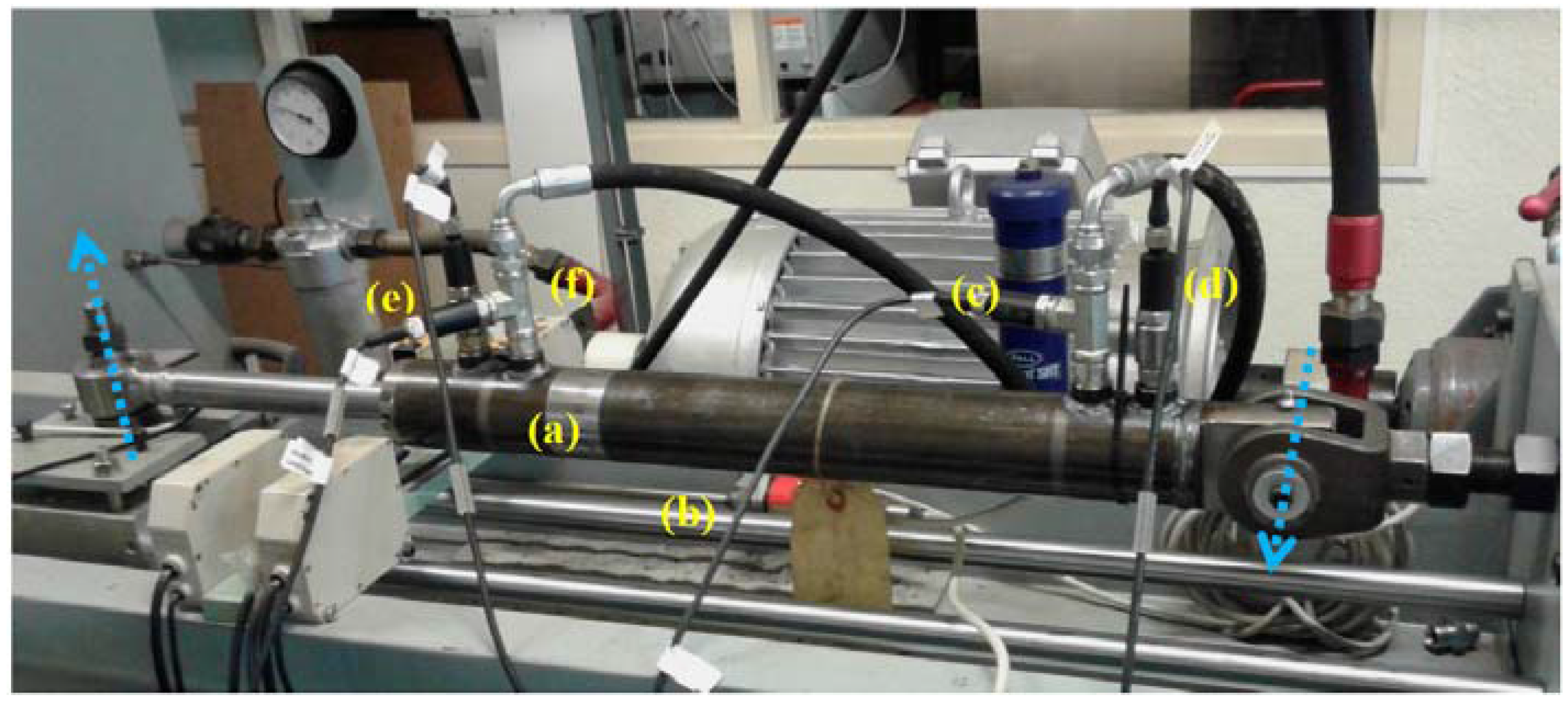
Figure 5.
Assembly configurations of the hydraulic cylinder: (a) perpendicular axis; and (b) parallel axis. Eddy current sensor position is marked in green.
Figure 5.
Assembly configurations of the hydraulic cylinder: (a) perpendicular axis; and (b) parallel axis. Eddy current sensor position is marked in green.
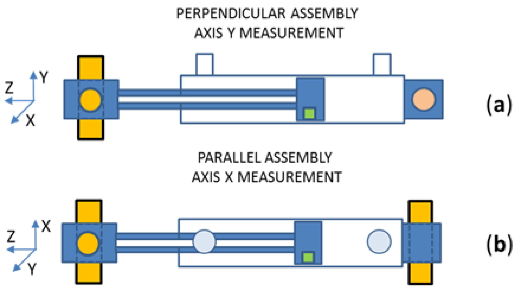
Figure 6.
S7 eddy current displacement sensor assembled in the piston. (a) General view of the piston; (b) detail of the sensor location.
Figure 6.
S7 eddy current displacement sensor assembled in the piston. (a) General view of the piston; (b) detail of the sensor location.

Figure 7.
Extension–retraction cycle of the hydraulic cylinder: (a,c) starting zones; and (b,d) end-stroke cushioning zones.
Figure 7.
Extension–retraction cycle of the hydraulic cylinder: (a,c) starting zones; and (b,d) end-stroke cushioning zones.

Figure 8.
Extension–retraction cycle: (a) extension starting and end-stroke cushioning speed; and (b) retraction starting and end-stroke cushioning speed.
Figure 8.
Extension–retraction cycle: (a) extension starting and end-stroke cushioning speed; and (b) retraction starting and end-stroke cushioning speed.
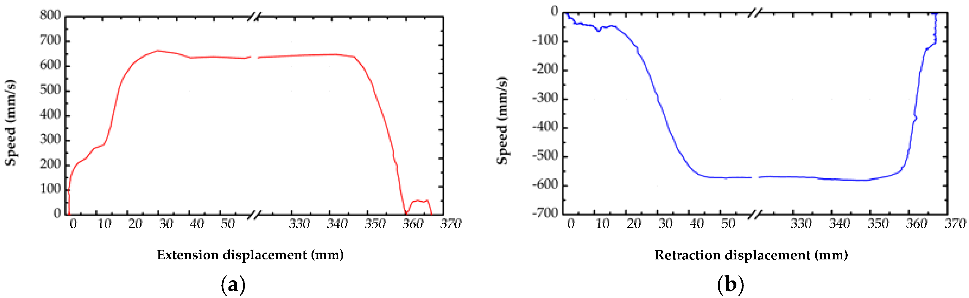
Figure 9.
Cushioning phases in relation with the relative position of the piston and oil outlet ports.
Figure 9.
Cushioning phases in relation with the relative position of the piston and oil outlet ports.
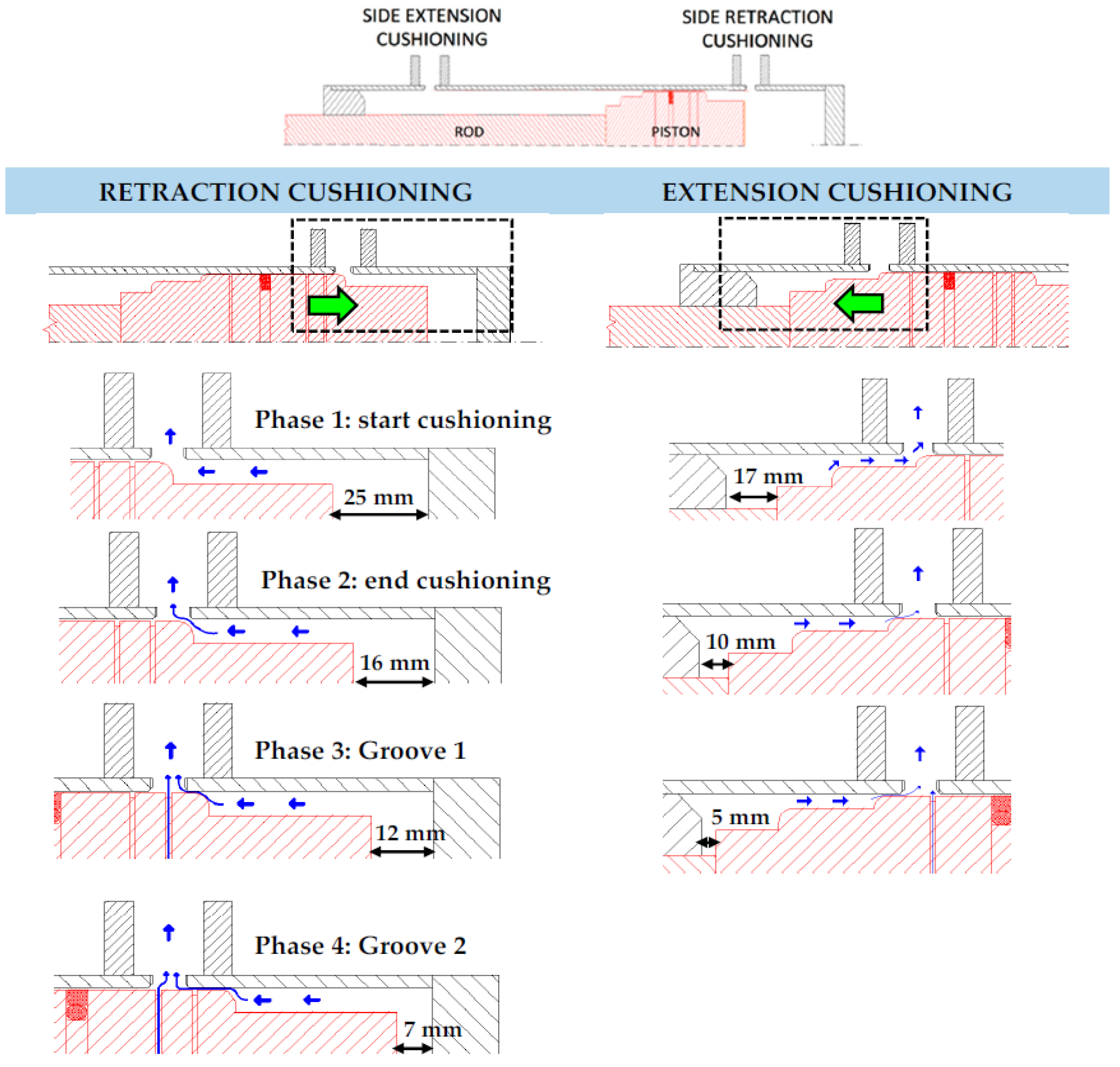
Figure 10.
Extension and retraction cushioning speed depending on operating conditions: (a) extension cushioning speed; and (b) retraction cushioning speed.
Figure 10.
Extension and retraction cushioning speed depending on operating conditions: (a) extension cushioning speed; and (b) retraction cushioning speed.

Figure 11.
Cylinder speed depending on operating conditions starting phase: (a) extension speed; and (b) retraction speed.
Figure 11.
Cylinder speed depending on operating conditions starting phase: (a) extension speed; and (b) retraction speed.

Figure 12.
Duration of the piston influence during characteristic zones: (a) extension starting; and (b) extension cushioning.
Figure 12.
Duration of the piston influence during characteristic zones: (a) extension starting; and (b) extension cushioning.
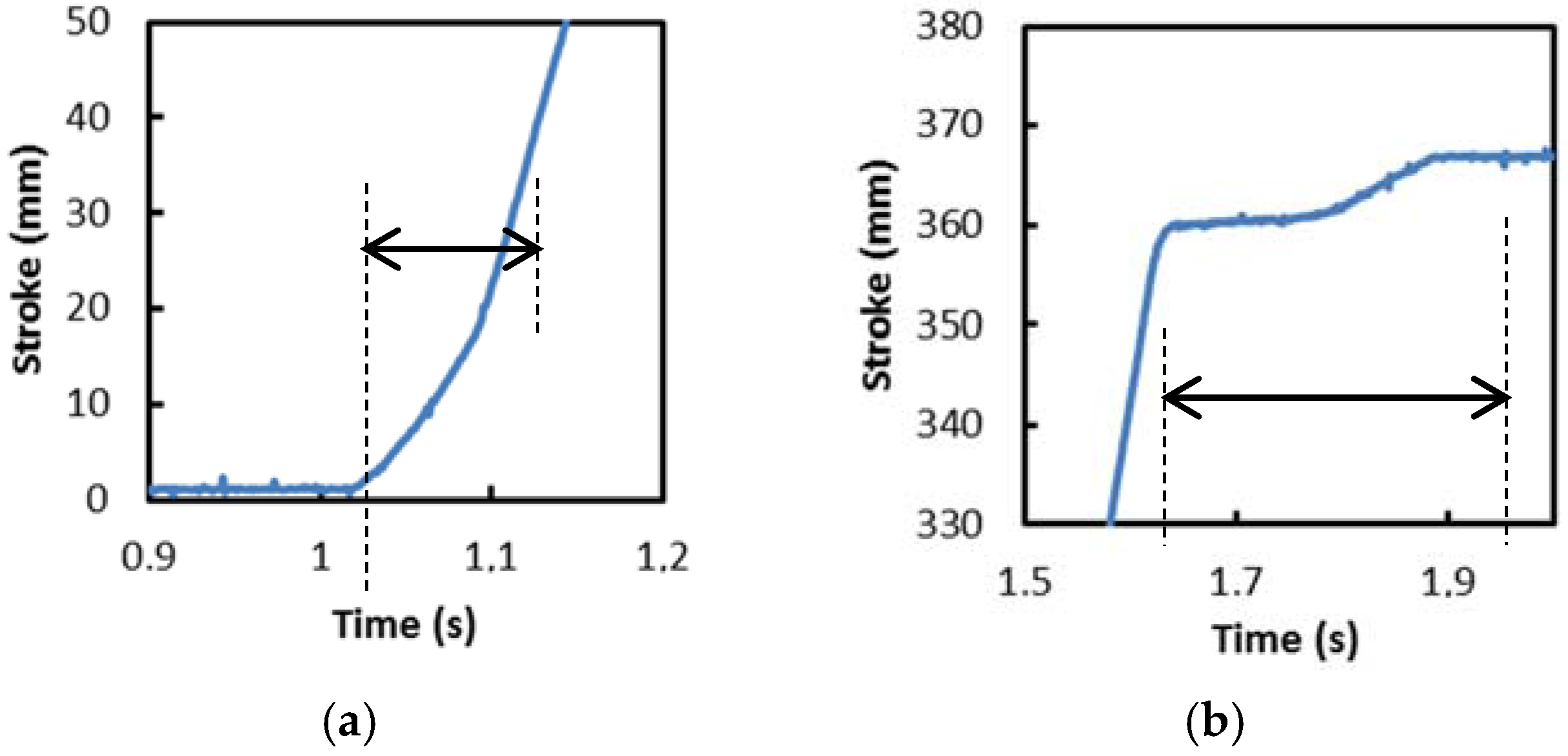
Figure 13.
Extension and retraction cushioning and starting duration depending on assembly positions of fixture axis of the cylinder: (a) extension movement; and (b) retraction movement.
Figure 13.
Extension and retraction cushioning and starting duration depending on assembly positions of fixture axis of the cylinder: (a) extension movement; and (b) retraction movement.
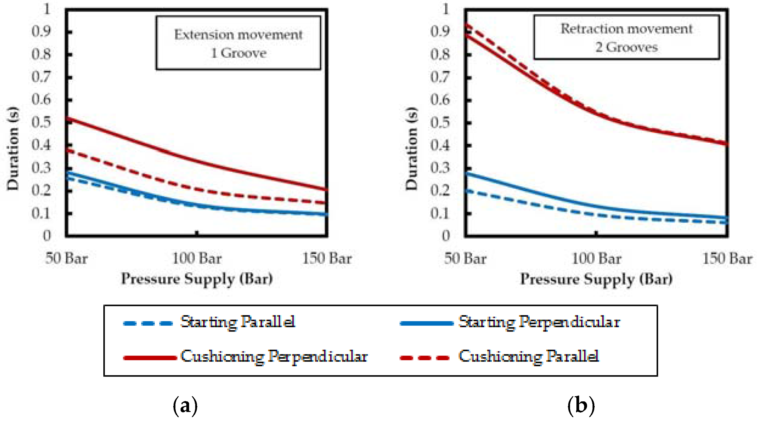
Figure 14.
Extension end-stroke cushioning pressure depending on operating conditions: (a) perpendicular fixation assembly; and (b) parallel fixation assembly.
Figure 14.
Extension end-stroke cushioning pressure depending on operating conditions: (a) perpendicular fixation assembly; and (b) parallel fixation assembly.

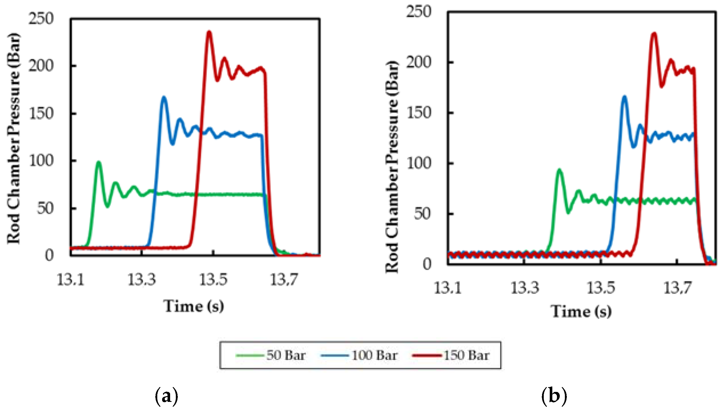
Figure 15.
Piston radial displacement for Perpendicular and Parallel fixation system assembly during an Extension–retraction cycle: starting zones (a,c); and end-stroke cushioning zones (b,d) remarked.
Figure 15.
Piston radial displacement for Perpendicular and Parallel fixation system assembly during an Extension–retraction cycle: starting zones (a,c); and end-stroke cushioning zones (b,d) remarked.

Figure 16.
Piston radial displacement of the cylinder in relation with fixation system assembly for an Extension-Retraction cycle: (a) perpendicular axis assembly; and (b) parallel axis assembly.
Figure 16.
Piston radial displacement of the cylinder in relation with fixation system assembly for an Extension-Retraction cycle: (a) perpendicular axis assembly; and (b) parallel axis assembly.

Figure 17.
Piston radial displacement (y axis) for perpendicular assembly: (a) cushioning extension; and (b) cushioning retraction.
Figure 17.
Piston radial displacement (y axis) for perpendicular assembly: (a) cushioning extension; and (b) cushioning retraction.

Figure 18.
Piston radial displacement (x axis) for parallel assembly: (a) cushioning extension; (b) and cushioning retraction.
Figure 18.
Piston radial displacement (x axis) for parallel assembly: (a) cushioning extension; (b) and cushioning retraction.
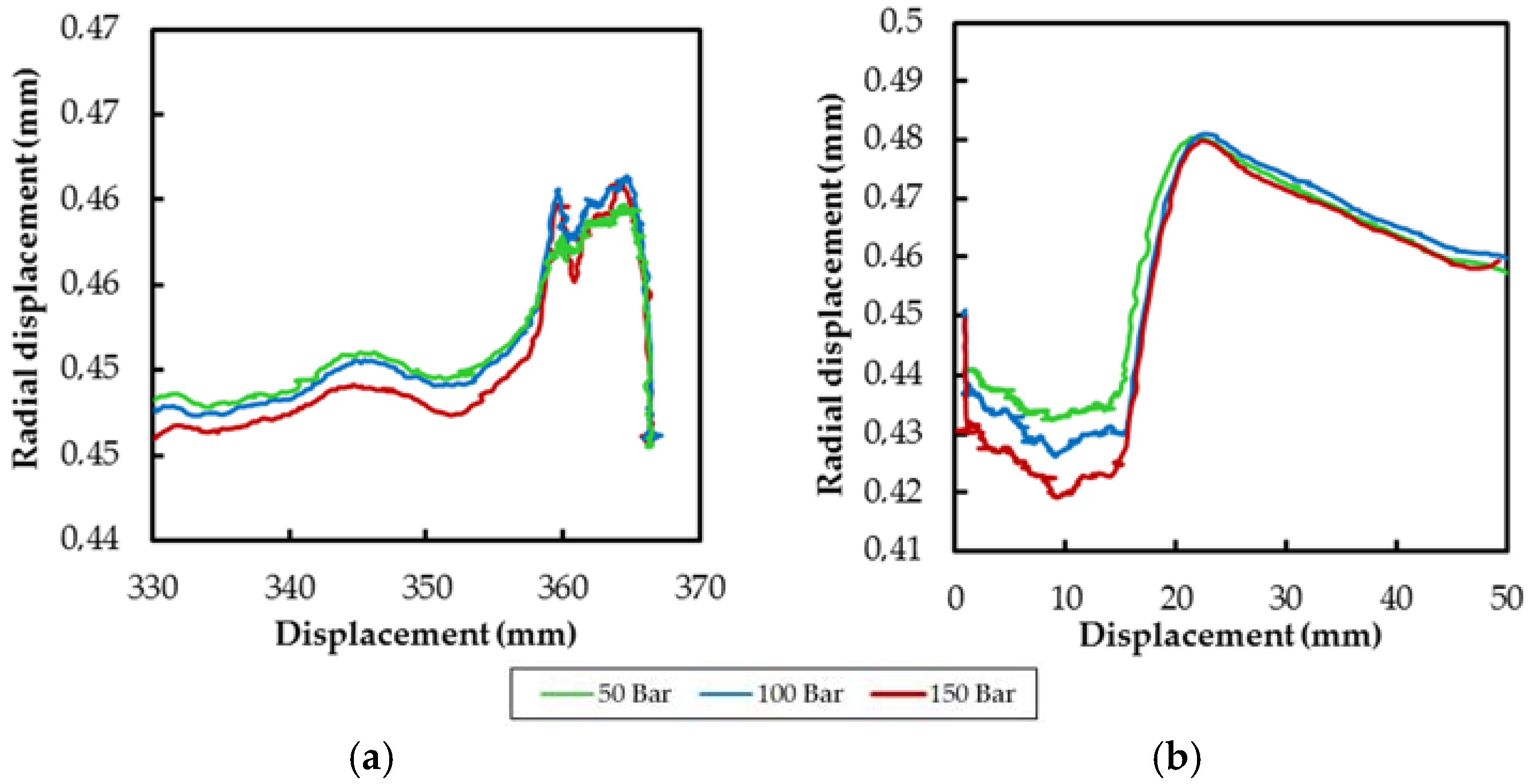
Figure 19.
Piston radial displacement (y axis) for perpendicular assembly: (a) starting extension; and (b) starting retraction.
Figure 19.
Piston radial displacement (y axis) for perpendicular assembly: (a) starting extension; and (b) starting retraction.

Figure 20.
Piston radial displacement (x axis) for parallel assembly: (a) starting extension; and (b) starting retraction.
Figure 20.
Piston radial displacement (x axis) for parallel assembly: (a) starting extension; and (b) starting retraction.

Figure 21.
Piston displacement at each characteristic zone: (a) y-z axis view; and (b) x-y axis view.
Figure 21.
Piston displacement at each characteristic zone: (a) y-z axis view; and (b) x-y axis view.

Figure 22.
Flow field through streamlines and pressure field; Up, Centre and Down.

Figure 23.
Transversal force during cushioning.


Table 1.
Identification of the hydraulic circuit components.
| Description | Component |
|---|---|
| Variable flow piston pump | P1 |
| Electric motor | M1 |
| Reservoir | Z1 |
| Directional valve | V1 |
| Pressure relief valve | V2 |
| Hydraulic cylinder | A1 |
| Pressure Transmitter—Range 0 to 250 bar ± 1% FSO | S1 to S5 |
| Eddy-current Displacement transducer—Range 0 to 0.5 mm ± 0.02% FSO | S6 |
| Displacement transducer—Range 0 to 950 mm ± 0.02% FSO | S7 |
Table 2.
CFD modeling.
| Mesh | Position | Characteristics | Turbulence Model | |
|---|---|---|---|---|
| 4 elements into the gap | Centre | Nodes | 444,494 | BSL Reynolds stress |
| Faces | 389,090 | |||
| Elements | 1,334,206 | |||
| Tetrahedrons | 968,296 | |||
| Prisms | 363,281 | |||
| Pyramids | 2629 | |||
| 8 elements into the gap | Centre | Nodes | 1,459,905 | BSL Reynolds stress |
| Faces | 698,393 | |||
| Elements | 3,787,816 | |||
| Tetrahedrons | 1,851,969 | |||
| Prisms | 1,921,637 | |||
| Pyramids | 14,210 | |||
| First element thickness constant all around | Up | Nodes | 2,408,754 | BSL Reynolds stress |
| Faces | 2,176,232 | |||
| Elements | 6,874,326 | |||
| Tetrahedrons | 4,782,836 | |||
| Prisms | 2,083,777 | |||
| Pyramids | 7713 | |||
| First element thickness constant all around | Down | Nodes | 2,859,686 | BSL Reynolds stress |
| Faces | 2,611,478 | |||
| Elements | 8,041,672 | |||
| Tetrahedrons | 5,514,068 | |||
| Prisms | 2,520,142 | |||
| Pyramids | 7662 | |||
© 2017 by the authors. Licensee MDPI, Basel, Switzerland. This article is an open access article distributed under the terms and conditions of the Creative Commons Attribution (CC BY) license (http://creativecommons.org/licenses/by/4.0/).
Share and Cite
MDPI and ACS Style
Algar, A.; Codina, E.; Freire, J. Experimental Study of 3D Movement in Cushioning of Hydraulic Cylinder. Energies 2017, 10, 746. https://doi.org/10.3390/en10060746
AMA Style
Algar A, Codina E, Freire J. Experimental Study of 3D Movement in Cushioning of Hydraulic Cylinder. Energies. 2017; 10(6):746. https://doi.org/10.3390/en10060746
Chicago/Turabian StyleAlgar, Antonio, Esteban Codina, and Javier Freire. 2017. "Experimental Study of 3D Movement in Cushioning of Hydraulic Cylinder" Energies 10, no. 6: 746. https://doi.org/10.3390/en10060746
Note that from the first issue of 2016, this journal uses article numbers instead of page numbers. See further details here.