
Wind Turbine Synchronous Reset Pitch Control
by
 , , and
Yolanda Vidal
† ,
,
Leonardo Acho
† ,
,
Ignasi Cifre
†,
Àlex Garcia
†,
Francesc Pozo
*,† and
and
José Rodellar
† Control, Dynamics and Applications (CoDAlab), Departament de Matemàtiques, Escola d’Enginyeria de Barcelona Est (EEBE), Universitat Politècnica de Catalunya (UPC), Campus Diagonal-Besòs (CDB), Eduard Maristany, 6–12, 08930 San Adrià de Besòs, Spain
*
Author to whom correspondence should be addressed.
†
These authors contributed equally to this work.
Energies 2017, 10(6), 770; https://doi.org/10.3390/en10060770
Submission received: 6 April 2017
/
Revised: 22 May 2017
/
Accepted: 27 May 2017
/
Published: 1 June 2017
(This article belongs to the Collection Wind Turbines)
Abstract
:Reset controllers are commonly used to smooth the transient response of systems. We use this technique to improve a standard baseline pitch controller for offshore wind turbines (WTs). The introduction of this strategy enhances the overall performance of the WT. In particular, the fore-aft and side-to-side accelerations of the WT tower are significantly reduced, whilst a steadier power output is obtained, in comparison to the standard baseline pitch controller. Furthermore, our designed pitch control’s main advantage, with respect to the baseline, is its ease of implementation and reduced complexity as it does not require a gain-scheduling technique, nor pitch position measurement (thus, it is insensitive to pitch sensor faults). The proposed approach has been simulated on the NREL 5-MW prototype offshore turbine model, mounted on a jacket support. The simulations are carried out using the aero-hydro-servo-elastic simulator FAST, and key observations are thoroughly discussed.
1. Introduction
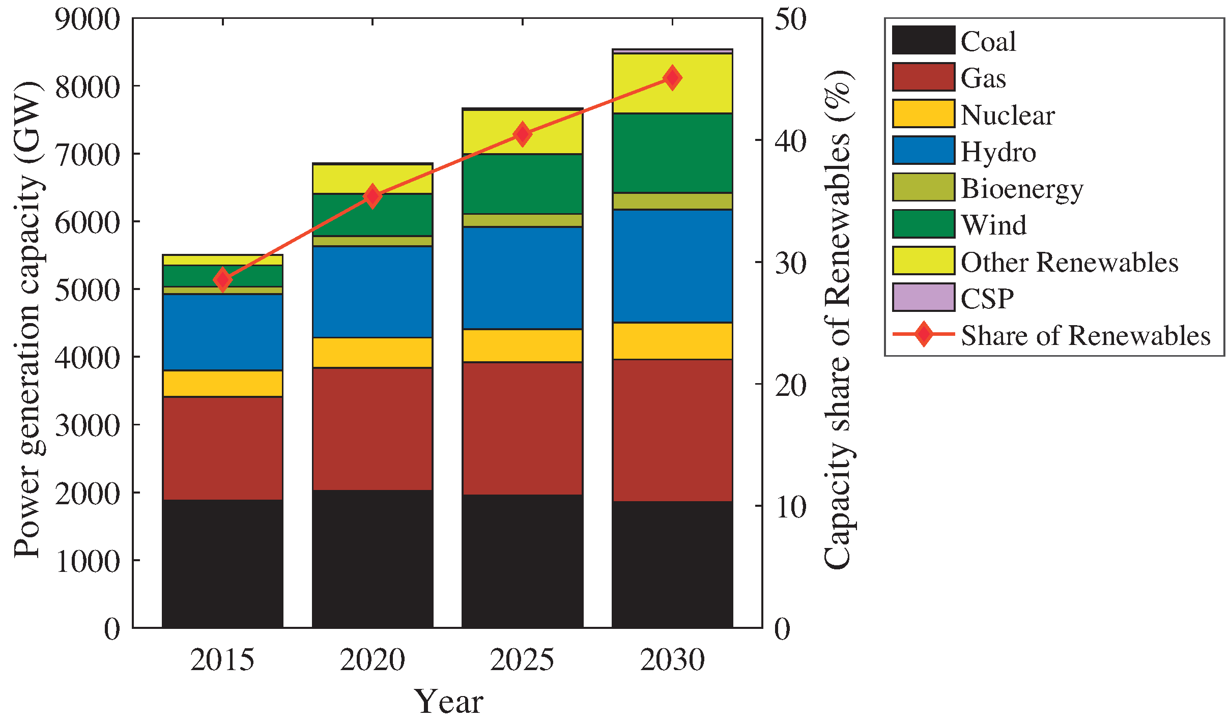
In the efforts towards decarbonization in the power generation industry, wind energy is playing one of the most important roles, as shown in Figure 1. It will be especially offshore wind energy that will account for the highest contributions due to its large-sized WTs, greater and steadier wind velocities that raise the capability of producing energy at a country-scale level and the fact that new suitable available onshore sites for deployments are becoming scarce particularly in Europe [1]. In order to increase the penetration of offshore wind energy into the energy market, its constant and effective development is required to achieve costs reduction.
The blade pitch control is, among the different WT control strategies, the one that could contribute a greater reduction of the levelized cost of energy [2]. Thus, by controlling the power harnessed at each moment, the blade pitch control enhances the operational flexibility of the WT, as well as providing stability, a greater robustness and a more efficient integration in the power grid. All modern high-power wind turbines (5 MW and above) use adjustable rotor speed operation, as their key advantages are well known, e.g., [3]. The pitch control design contributes also to maintain the wind tower vibrations within acceptable limits. On this matter, in the work by Jonkman et al. [4], a controller for a 5-MW offshore wind turbine is proposed. This has become a commonly-used controller in the industry, and it is nowadays used in research for comparison to new control developments (e.g., [5,6,7,8]). Thus, it is used in this work and denoted here as the baseline controller.
This work provides an improved methodology regarding the pitch control strategy currently proposed for large-scale wind turbines (WTs). In particular, a modification of the baseline controller is presented based on synchronous reset control. This novel modification simplifies the controller complexity leading to a better performance. Regarding the complexity, it does not require a gain-scheduling technique, nor pitch position measurement (thus, it is insensitive to pitch sensor faults). On the other hand, related to its performance and according to the numerical simulations, the fore-aft and side-to-side accelerations of the WT tower are considerably attenuated. This is an important achievement from the structural point of view (e.g., [9]). In addition, the quality of the electrical power generation is also improved.
The remainder of this paper is structured as follows. Section 2 includes a succinct introduction to reset controllers highlighting their main properties. The state of the art of the different WT control strategies is given in Section 3. In Section 4, the wind turbine benchmark is recalled, as well as the baseline pitch and torque controllers. Section 5 presents the design of the synchronous reset pitch controller (SRP). The simulation results obtained with the proposed pitch controller applied to the 5-MW wind turbine benchmark are given in Section 6. Concluding remarks are given in Section 7.
2. Reset Controllers
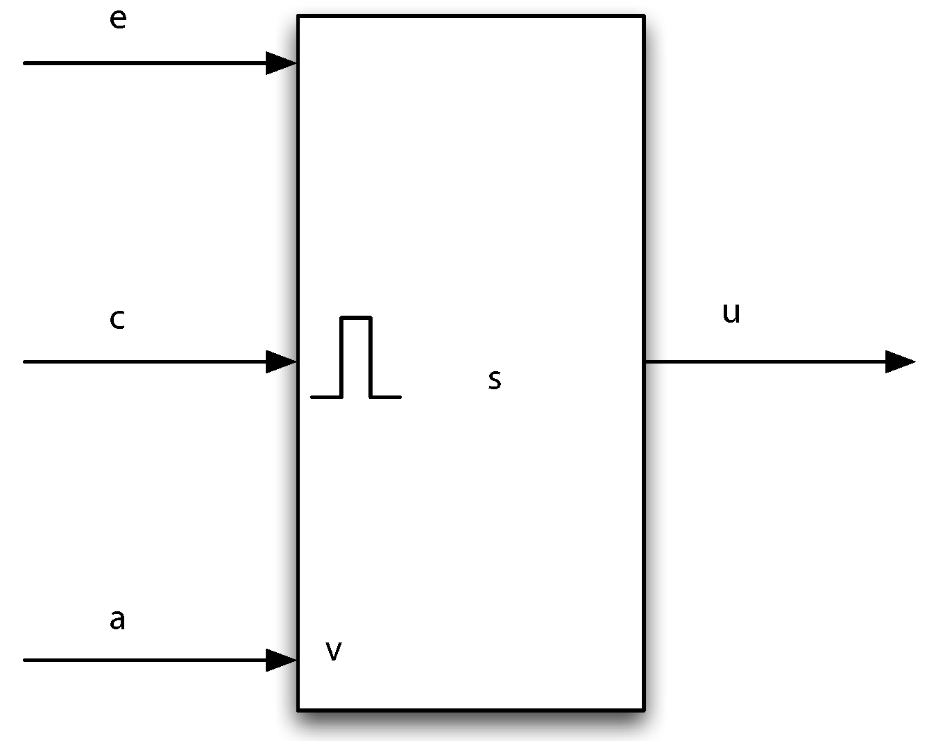
Reset controllers appeared for the first time in 1958, when J. C.Clegg proposed a reset controller that had the aim of improving the transient response of closed-loop systems [10]. This improvement was advantageous for integral-type controllers due to its ability to reduce the overshooting or phase lagging, increasing the flexibility of the system. Generally speaking, Clegg’s main idea was that, whenever the user-defined reset condition, , is met, the reset action is applied to the integral part of the controller, , that is set to a new user-defined reset initial condition, . Due to this resetting condition, the transient response of controlled systems can be manipulated (such as the settling time, the rise time or the overshoot). The equations of this basic reset integrator are [11]:
where is the controller input. Figure 2 shows its block diagram representation.
3. State of the Art of WT Pitch Controllers
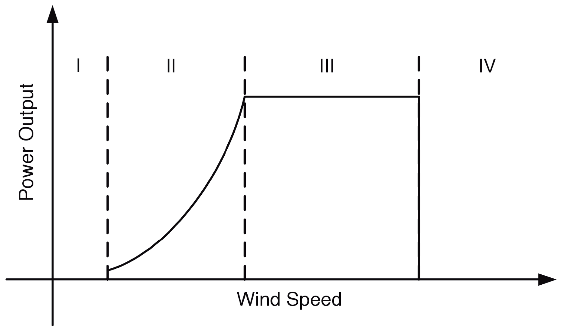
Wind turbines are complex systems with large flexible structures that work under very turbulent and unpredictable environmental conditions; thus the need for advanced (multivariable and multiobjective) control systems concerned with optimization and quality improvement of the generated power, speed/power regulation and/or the reduction of structural load in wind turbines. This section discusses various advanced control methods that are used in large WT in the full load region. The power production capability of a wind turbine is often presented in relation to wind speed, as shown in Figure 3. From the figure, we see four regions of operation. Region I is the start up stage. As the wind accelerates beyond the cut-in speed, we enter Region II. A common control strategy in this region is to keep the pitch angle constant while controlling the generator torque. At the point where the wind speed is higher than the rated wind speed of the turbine (rated speed), we enter Region III. In this region, the torque is normally kept constant, and the controlling parameter is the pitching angle, thus the importance of the pitch control. This is the region we are concerned with in this paper, i.e., the so-called full load region. The last region is the shutting-down phase (cut-out).
In Table 1, different control methods developed for the high wind speed region are given. Most of these methods are based on linear control theory, meaning that they are only effective around a given operation point. Therefore, measures must be taken to compensate for uncertainties resulting from the change of operation point due to the variation of incoming wind speed. Although the PI gain scheduling controller is simple to design and more robust, it has limitations in handling multi-objective problems since it is a single-input single-output controller. Linear quadratic Gaussian (LQG) methods can offer an optimal solution by trading-off opposing requirements by minimizing a given cost function. In most cases, full system state information is required to design this class of controllers, but not all states are available for measurements; thus the need to design observers to reconstruct unknown states. In the literature, LQG has been applied to regulate the generator speed and reduce the structural loads, where it is assumed that the wind turbine is influenced by disturbances and noise that have some assumed stochastic properties. Due to these requirements, LQG controllers are restricted in terms of applications. Another problem associated with the LQG controller is poor gain margins, which are improved using loop transfer recovery. Fuzzy logic control (FLC) for individual pitch control has been proven to optimize a trade-off among several control objectives, such as to mitigate fatigue loads and regulate output power. The use of classical sliding mode control (SMC) for WT control deals efficiently with the power regulation objective and provides the advantage of robustness against system uncertainties and perturbations, such as measurement noise. Although classical SMC has shown good performance in an uncountable number of applications, its well-known drawback has been the discontinuous behavior of the computed control inputs that may derive it into a high-frequency oscillation known as chattering (see [16]). Among the great variety of chattering suppression methods, so-called high-order sliding mode control has been intensively studied within the last decade. As noted, individual pitch control leads to increased pitch duty cycle, which may in turn cause the early failure of pitching mechanism. To tackle this problem, model predictive control (MPC) has been considered in many studies, since it can explicitly take into account constraints during the design stage to avoid the violation of pitching actuator limits. To further improve the performance of MPC, LIDAR (light imaging, detection and ranging) measurements can also be used to improve its reaction time.
4. Reference Offshore Wind Turbine
In this work, the National Renewable Energy Lab (NREL) offshore 5-MW baseline wind turbine given in [4] is used. As a system that represents the current state of the art in an offshore WT, this baseline turbine concept has been extensively employed in studies by the wind energy research community and has supported numerous research topics including, for instance, aerodynamics, offshore dynamics or design control code development, e.g., [8,28]. Its main data are summarized in Table 2. In this work, as a research object, the jacket support platform is selected as the turbine support structure [29].
In this work, sensors are modeled in Simulink by adding signals from band-limited white noise blocks, which are parameterized by noise power, to the actual variables provided by FAST; see [17]. These random noise blocks represent measurement noise either due to the measuring principle or due to electrical noise in the system. Table 3 shows the simulated sensors and its noise power.
In [4], standard baseline pitch and torque controllers are given for the 5-MW reference WT. These controllers are frequently used in the industry, and they are used in research, in conjunction with the FAST (Fatigue, Aerodynamics, Structure and Turbulence) software, for the comparison to new control developments. See Section 7 of [4] for a high level detailed explanation about the development of the wind turbine’s baseline control system. In the following sections, these controllers are briefly recalled in the full-load region of operation along with the blade-pitch actuator model and the generator-converter model.
As is typical in utility-scale megawatt wind turbines, both the generator-torque and blade-pitch controllers use the generator speed measurement as a feedback input. To mitigate high-frequency excitation of the control systems, the generator speed measurement is filtered, for both the torque and pitch controllers, using a recursive, single-pole low-pass filter with exponential smoothing [4].
4.1. Baseline Pitch Controller
In the above-rated wind speed region, the baseline pitch controller is a collective gain-scheduling PI-controller on the error between the filtered generator speed and the rated generator speed. That is,
where is the filtered generator speed, and are the proportional and integral gains and is the pitch servo set point. The gain-scheduled parameters depend on , which is the rotor-collective blade-pitch angle from the previous controller time step. The blade-pitch rate limit is set to 8/s in absolute value, and the minimum and maximum blade-pitch settings are 0 and 90, respectively [4].
4.2. Baseline Torque Control
In the full load region, the generator-torque controller’s objective is to held constant the generated power. Thus, the generator torque, , is inversely proportional to the filtered generator speed, (see [4]),
where is the nominal generator power.
4.3. Blade-Pitch Actuator
The FAST model does not include any blade-pitch actuator dynamic effects. Here, a second order pitch actuator model is used [17],
where is the damping factor and is the natural frequency. In this work, the values and rad/s are used [17].
In order to provide a more realistic actuator model, the non-linear backlash phenomenon is included. According to the hydraulic pitch actuator general specifications stated in [30], a realistic dead band value for our backlash model is 0.5.
4.4. Generator-Converter Model
5. Synchronous Reset Pitch Controller
In this section, the proposed pitch controller is explained. It is a redesign of the baseline controller.
Firstly, as already said, a reset integrator is introduced in the integral part. The steps to design this synchronous integral reset are as follows.
- Controller input: The error in the regulation of the generator speed is used as the controller input, that is .
- Reset condition: A time periodic signal to activate the resets at periodic fixed time steps is used. In particular, . The frequency is taken as Hz after developing a simple trial-and-error analysis comprising values between 1 Hz and 40 Hz.
- Reset initial condition: The mean value of the pitch control baseline simulations, when operating in the overload region, is about 15. Therefore, the reset initial condition, , is set to this value. Intuitively speaking, with this action, the integral part of the reset-controller will approximately follow this average.
Secondly, the proportional and integral gains are fixed. That is, there is no need for a gain-scheduling; therefore, we set and . These values correspond to the gain scheduling parameters of the baseline controller when .
The proposed controller will be denoted as the synchronous reset pitch (SRP) controller throughout this work.
5.1. Brief Comments on Stability
The baseline pitch controller is in fact an auto-tuning PID controller and developed with barely a stability proof [4]. However, some insight on stability issues can be inferred for our proposed reset control by taking into account the main assumptions done for the torque baseline controller. As previously said, the used torque controller has the objective of regulating the generator power to its nominal value by applying a bounded control torque, thus implying that rotor speed is also bounded. Then, the generator speed error is bounded, and therefore, the proportional part of the reset pitch control is also bounded. Finally, as we are using integral synchronous resetting, its integral part is also bounded. Then, it follows that the proposed reset pitch controller supplies a bounded signal. Hence, and from Equation (4), BIBO stability can be concluded for the pitch dynamics.
Finally, note that a formal analysis is beyond the scope of this paper; however, it will be covered in our future work.
6. Simulation Results
This section presents the performance evaluation of the proposed pitch controller with respect to the baseline one.
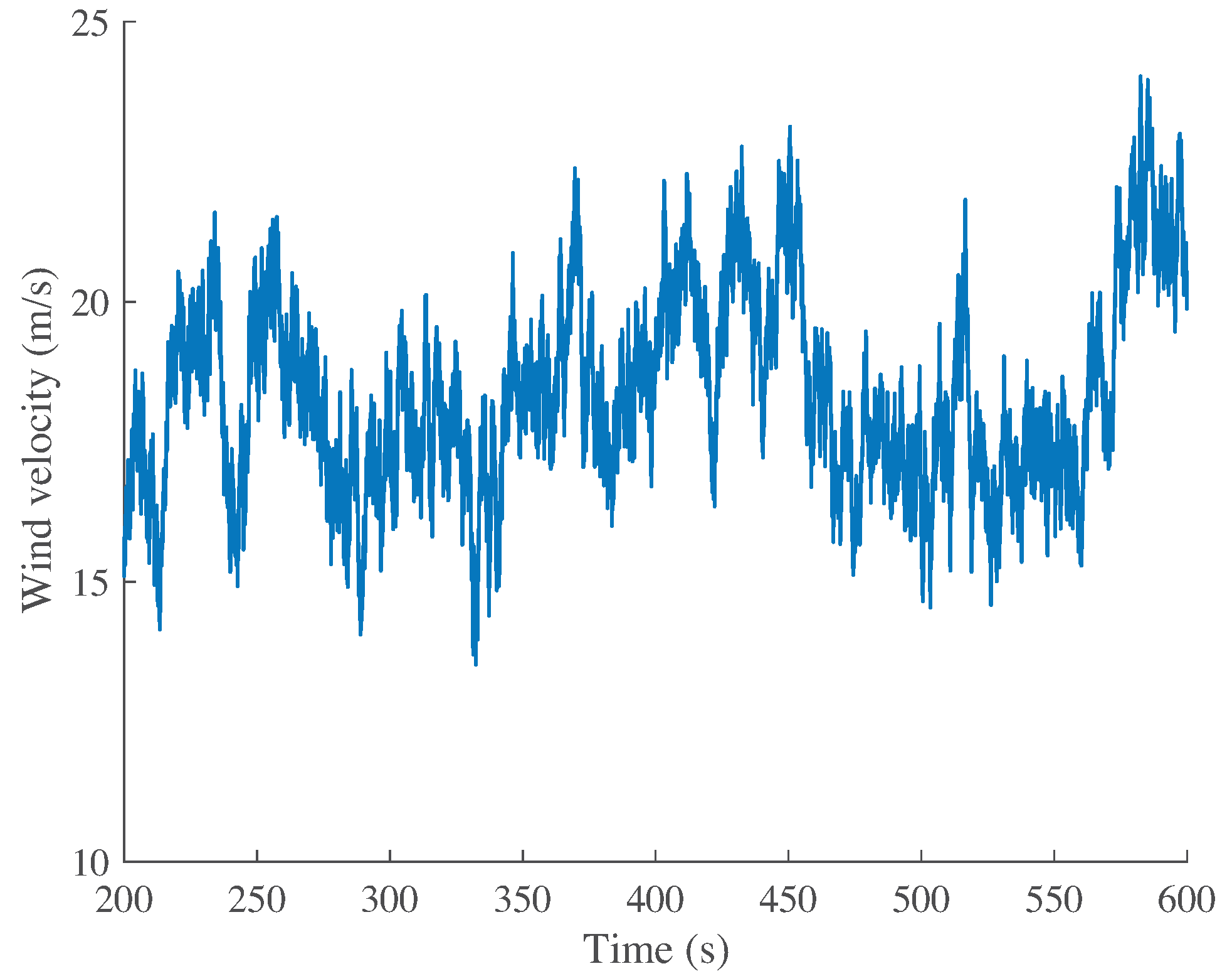
The stochastic, full-field, turbulent-wind simulator Turbsim [31] has been used to generate the wind speed used in the simulations. Figure 4 shows the effective wind speed that reaches values above the rated power operating conditions, as this work focuses on this region. The maximum and minimum wind speeds are and m/s, respectively, with a mean speed of m/s, while the rated wind speed for the offshore NREL 5-MW wind turbine is m/s. It is clearly observed that it is a non-stationary wind profile.
The following performance indices are employed, to present a comparison between the tested controllers [32]:
where and are the fore-aft and the side-to-side accelerations, respectively, at the tower top.
Remark 1.
6.1. Results and Discussion
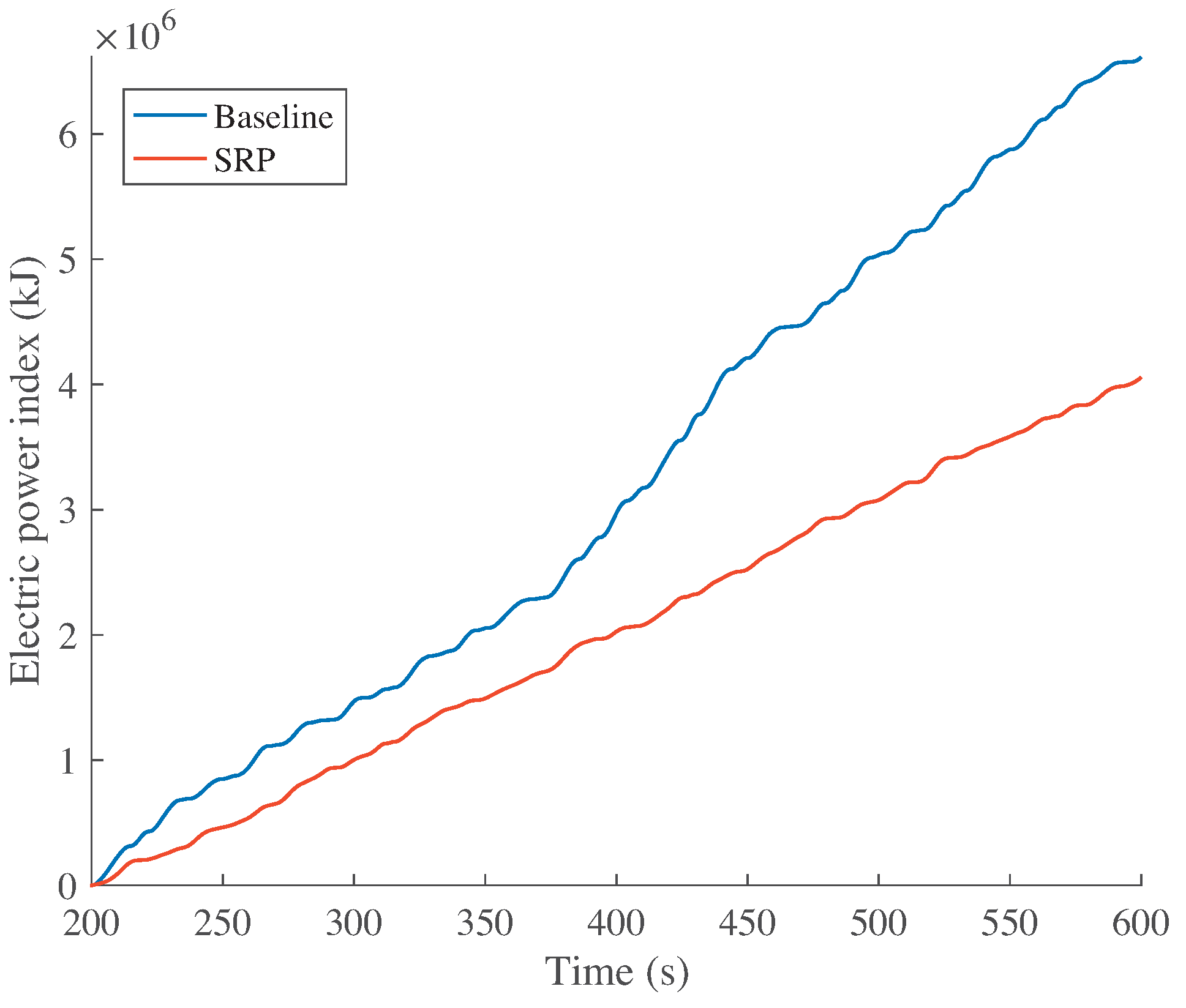
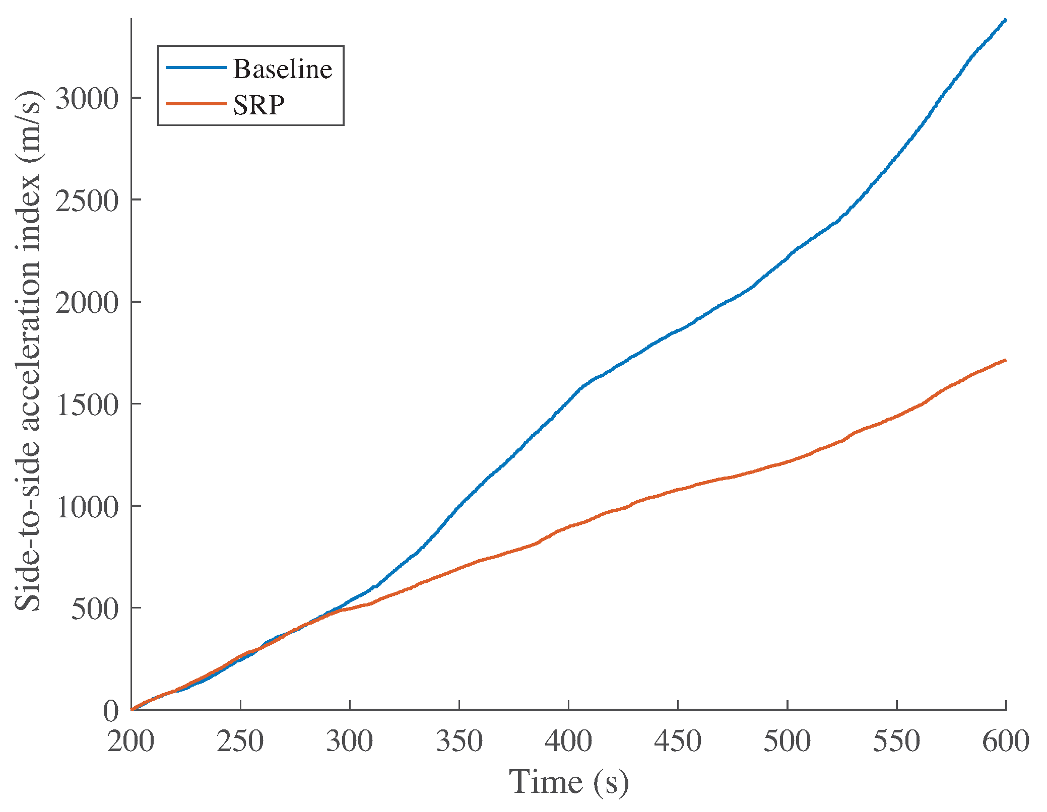
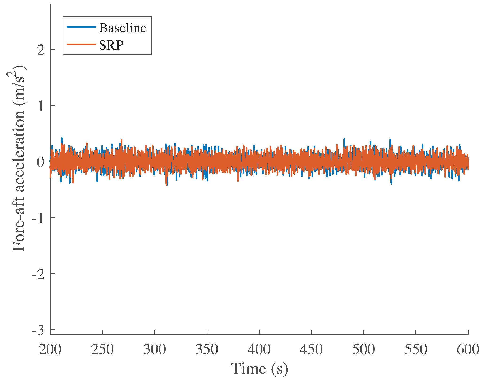
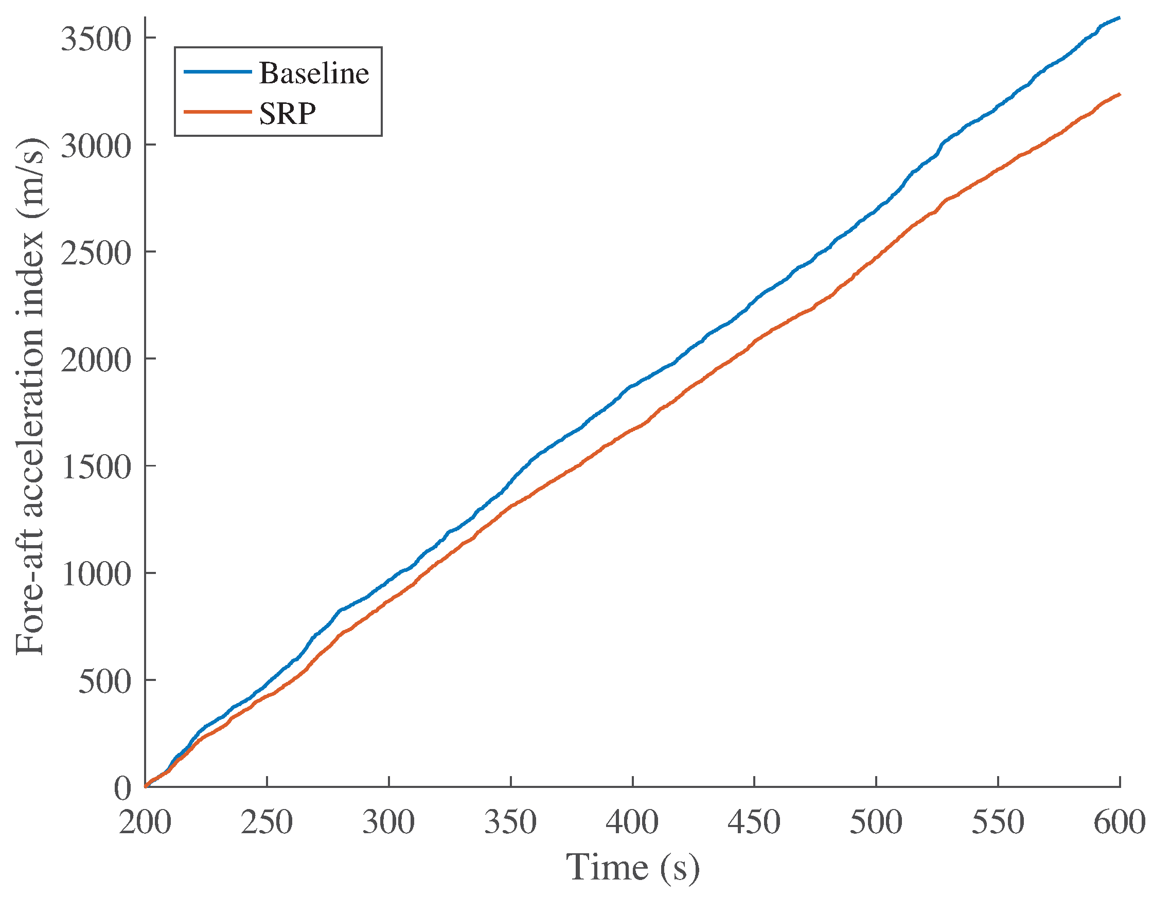
Figure 5, Figure 6, Figure 7, Figure 8, Figure 9, Figure 10, Figure 11, Figure 12, Figure 13, Figure 14 and Figure 15 show the performance of the WT. These figures compare the results of the baseline control and the SRP control. At a glance, it is observed that all indices are reduced by the proposed SRP. In particular, the regulation of the generated power is enhanced, as can be seen in Figure 5 and Figure 6. It is noteworthy that the fore-aft and side-to-side accelerations are significantly reduced, as shown in Figure 7, Figure 8, Figure 9 and Figure 10.
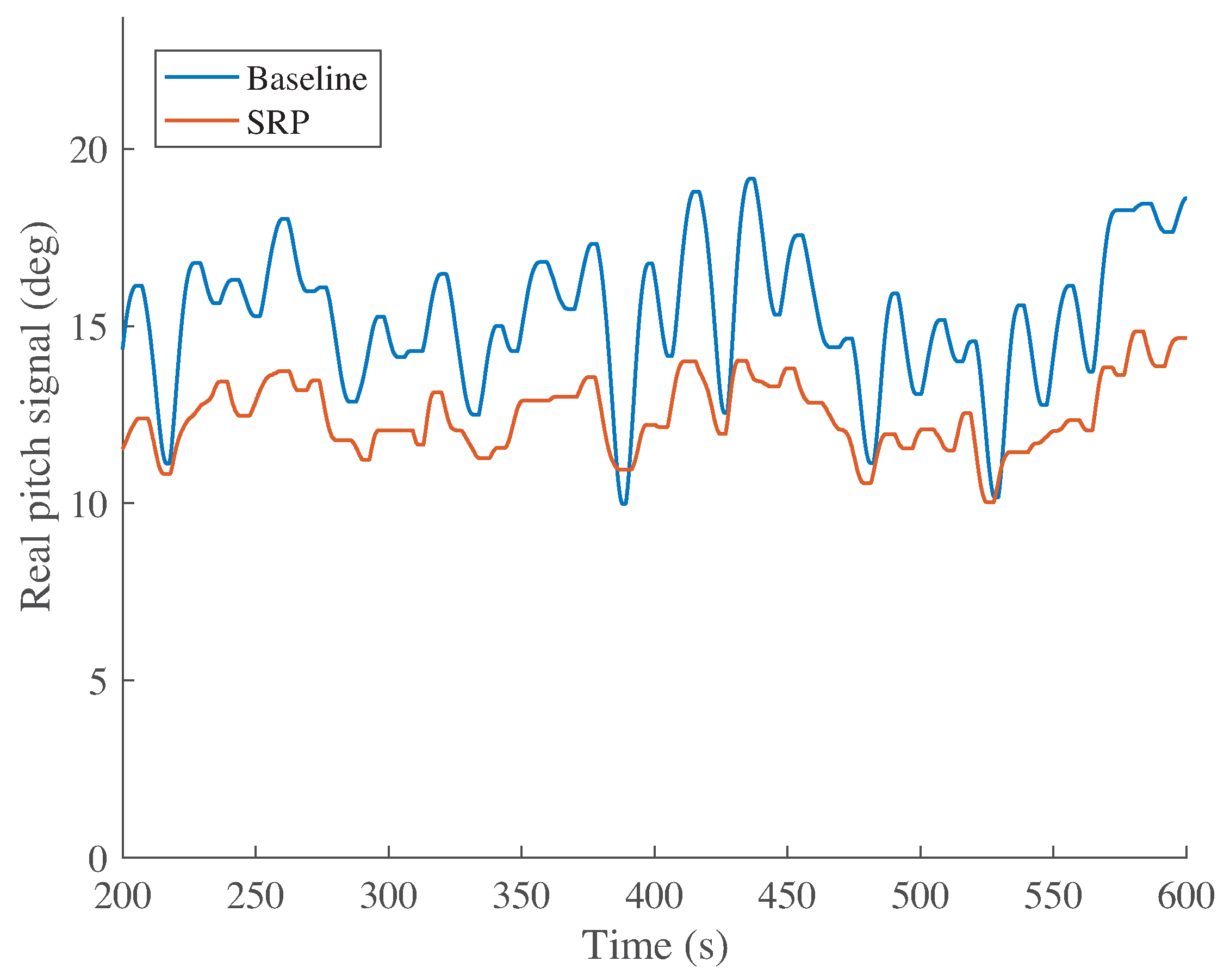
With respect to the pitch control signal, , it reflects the resets’ influence by the appearance of high frequencies (see Figure 11 and Figure 12). Nevertheless, the general trend of the signals is similar in both simulations, the displacement of the average from 15 (baseline) to 12 (SRP) being the only difference to note. With respect to the real pitch signal, , shown in Figure 13, the effect of the backlash phenomena by the appearance of dead-band regions in which the blade is stuck is relevant. The dead-band regions are increased in the simulation with the SRP control, probably motivated by the high frequencies coming from the control signal.
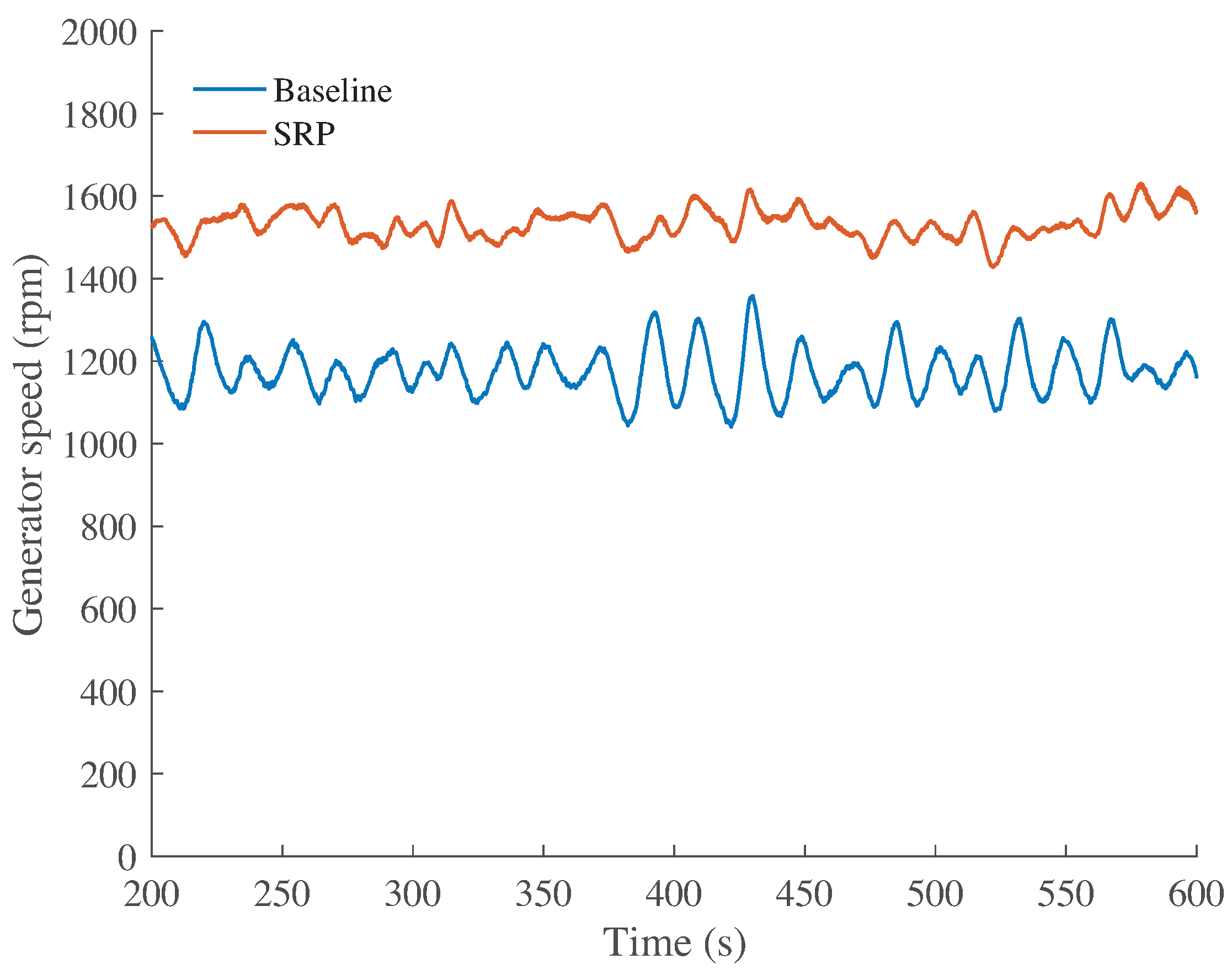
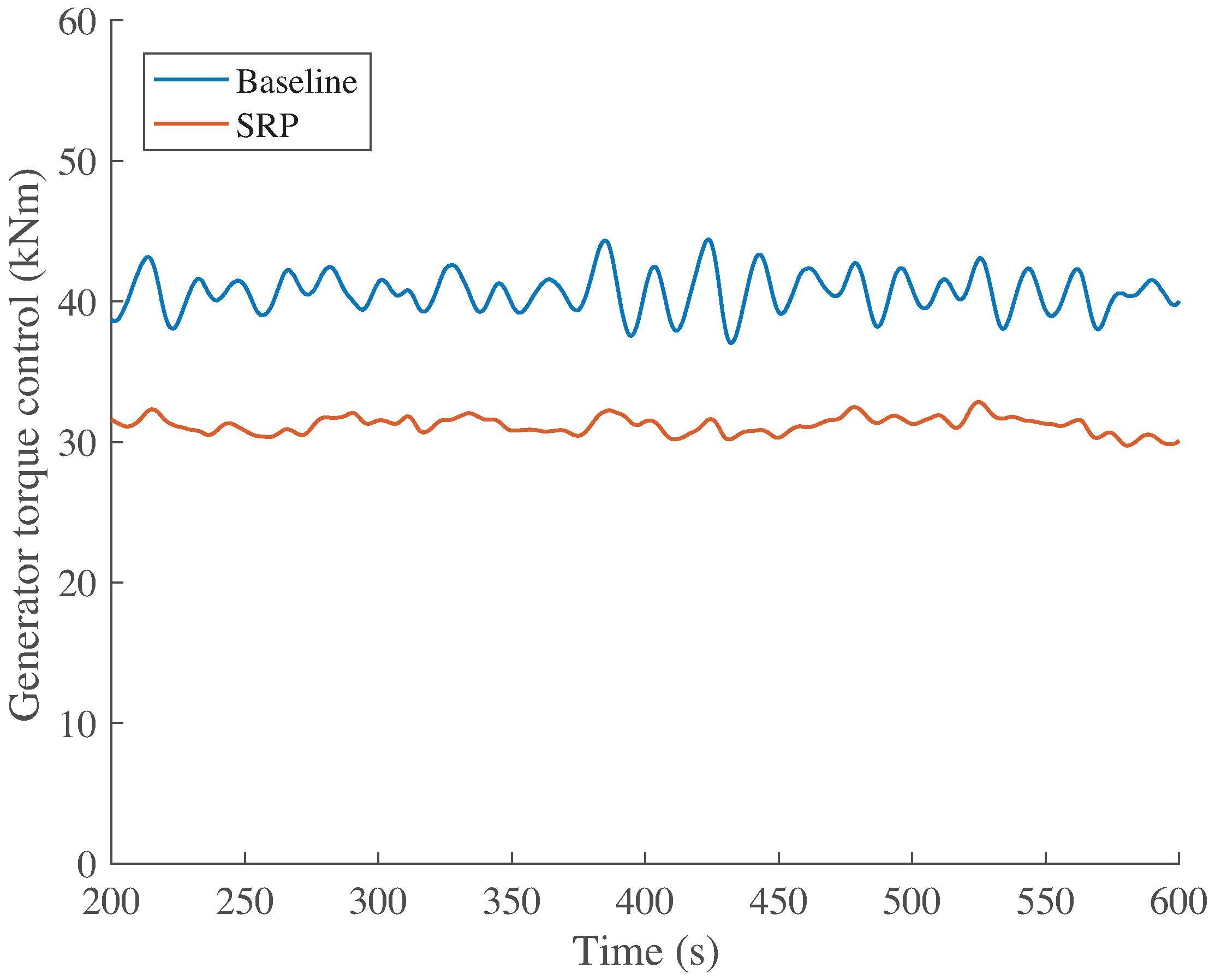
Regarding the generator, its speed and torque are depicted in Figure 14 and Figure 15, respectively. Both characteristics of the generator are complemented since the electric power output is the outcome of their multiplication, as defined in Equation (6). As shown in Figure 14, the generator speed is similar for both controllers, although instead of ranging around 1200 rpm (baseline), it is now close to 1500 rpm (SRP). Finally, as a consequence of the higher generator speed, the torque control for the SRP is around 30 kNm, whilst for the baseline control, it is close to 40 kNm, as observed in Figure 15.
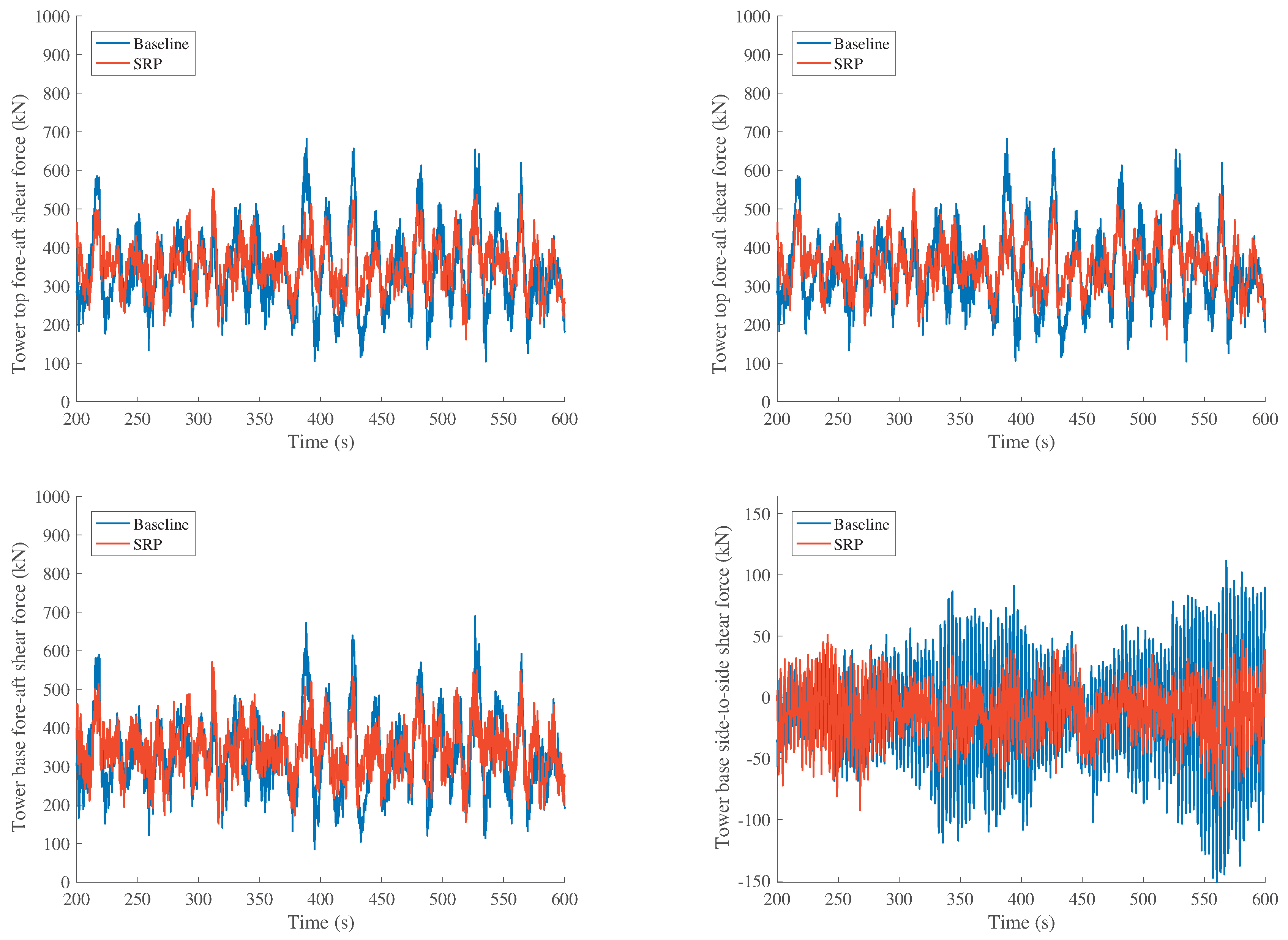
The platform rotational (pitch and roll) and translational (surge and sway) data are shown in Figure 16. A reduction is obtained in all of the displacements with the proposed SRP, with respect to the baseline controller. Similarly, the tower base and tower top fore-aft and side-to-side shear force data are shown in Figure 17. Again, with respect to the baseline controller, a reduction is observed with the proposed SRP.
7. Conclusions
This work addressed the design of a synchronous reset pitch (SRP) control for a large off-shore wind turbine with a jacket platform operating in the full-load region. With respect to the baseline, the proposed SRP turns out to be a controller with a reduced complexity as it does not require a gain-scheduling technique, nor the pitch position measurement as input. Furthermore, it improves the overall performance of the wind turbine, with respect to the baseline. In particular, the fore-aft and side-to-side acceleration are significantly reduced, and the generated power is better regulated. In a nutshell, the designed SRP is a simpler, but more efficient controller when compared to the baseline.
Moreover, this paper demonstrates that the SRP can have a decisive role in the process of providing WT with the advantageous levels of stability and robustness required by the offshore operation. The implementation of the SRP ameliorates the WT performance by reducing its vibrations and increasing the flexibility of the power harnessed from the wind. Consequently, the reset control systems can have a crucial function in the deployment of offshore wind farms.
Finally, the main advantage of the proposed controller, besides all of the improvements mentioned in this paper, is its ease of implementation. It only requires changes in the software algorithm, thus being an inexpensive measure that can be rapidly implemented not only in new WT, but also in already existing ones, as long as those are gifted with a control system.
Acknowledgments
The third and fourth authors would like to thank the Spanish Ministry of Education, Culture and Sports for the scholarship that made their work with the research group CoDalabin the Department of Mathematics at the Universitat Politècnica de Catalunya (UPC) possible. This work has been partially funded by the Spanish Ministry of Economy and Competitiveness through the research projects DPI2014-58427-C2-1-R and DPI2015-64170-R (MINECO/FEDER) and by the Catalonia Government (Generalitat de Catalunya) through the research project 2014SGR 859.
Author Contributions
All of the authors contributed equally to this work.
Conflicts of Interest
The authors declare no conflict of interest. The founding sponsors had no role in the design of the study; in the collection, analyses or interpretation of data; in the writing of the manuscript; nor in the decision to publish the results.
Abbreviations
The following abbreviations are used in this article (in alphabetical order):
| BIBO | bounded-input bounded-output |
| FAST | Fatigue, Aerodynamics, Structure and Turbulence |
| FLC | fuzzy logic control |
| INDC | intended nationally-determined contributions |
| LQG | linear quadratic Gaussian |
| MPC | model predictive control |
| NREL | National Renewable Energy Lab |
| PID | proportional-integral-derivative |
| SISO | single input single output |
| SMC | sliding mode control |
| SRP | synchronous reset pitch controller |
| WT | wind turbine |
References
- Soukissian, T. Use of multi-parameter distributions for offshore wind speed modeling: The Johnson SB distribution. Appl. Energy 2013, 111, 982–1000. [Google Scholar] [CrossRef]
- World Energy Outlook (WEO). Special Report in Energy and Climate Change (World Energy Outlook 2015); Technical Report; International Energy Agency (IEA): Paris, France, 2015. [Google Scholar]
- Muller, S.; Deicke, M.; De Doncker, R.W. Doubly fed induction generator systems for wind turbines. IEEE Ind. Appl. Mag. 2002, 8, 26–33. [Google Scholar] [CrossRef]
- Jonkman, J.M.; Butterfield, S.; Musial, W.; Scott, G. Definition of a 5-MW reference wind turbine for offshore system development. Contract 2009, 1–75. [Google Scholar] [CrossRef]
- Tian, J.; Zhou, D.; Su, C.; Soltani, M.; Chen, Z.; Blaabjerg, F. Wind Turbine Power Curve Design for Optimal Power Generation in Wind Farms Considering Wake Effect. Energies 2017, 10, 395. [Google Scholar] [CrossRef]
- Goit, J.P.; Munters, W.; Meyers, J. Optimal coordinated control of power extraction in LES of a wind farm with entrance effects. Energies 2016, 9, 29. [Google Scholar] [CrossRef]
- Mirzaei, M.; Hansen, M.H. A LIDAR-assisted model predictive controller added on a traditional wind turbine controller. In Proceedings of the IEEE 2016 American Control Conference (ACC), Boston, MA, USA, 6–8 July 2016; pp. 1381–1386. [Google Scholar]
- Vidal, Y.; Tutivén, C.; Rodellar, J.; Acho, L. Fault diagnosis and fault-tolerant control of wind turbines via a discrete time controller with a disturbance compensator. Energies 2015, 8, 4300–4316. [Google Scholar] [CrossRef]
- Tutivén, C.; Vidal, Y.; Rodellar, J.; Acho, L. Acceleration-based fault-tolerant control design of offshore fixed wind turbines. Struct. Control Health Monit. 2016. [Google Scholar] [CrossRef]
- Clegg, J. A nonlinear integrator for servomechanisms. Trans. Am. Inst. Electr. Eng. Part II Appl. Ind. 1958, 77, 41–42. [Google Scholar] [CrossRef]
- Baños, A.; Barreiro, A. Reset Control Systems; Springer-Verlag: London, UK, 2011. [Google Scholar]
- Baños, A.; Carrasco, J.; Barreiro, A. Reset times-dependent stability of reset control systems. IEEE Trans. Autom. Control 2011, 56, 217–223. [Google Scholar] [CrossRef]
- Aangenent, W.; Witvoet, G.; Heemels, W.; Van De Molengraft, M.; Steinbuch, M. Performance analysis of reset control systems. Int. J. Robust Nonlinear Control 2010, 20, 1213–1233. [Google Scholar] [CrossRef]
- Yang, T. Impulsive Control Theory; Springer-Verlag: Berlin, Germany, 2001; Volume 272. [Google Scholar]
- Bauinov, D.; Simeonov, P.S. Systems with Impulse Effect: Stability, Theory, and Applications; Ellis Horwood: Chichester, UK, 1989. [Google Scholar]
- Utkin, V.; Guldner, J.; Shi, J. Sliding Mode Control in Electro-Mechanical Systems; CRC press: Boca Raton, FL, USA, 2009; Volume 34. [Google Scholar]
- Odgaard, P.F.; Johnson, K.E. Wind turbine fault detection and fault tolerant control-an enhanced benchmark challenge. In Proceedings of the IEEE 2013 American Control Conference (ACC), Washington, DC, USA, 17–19 June 2013; pp. 4447–4452. [Google Scholar]
- Wright, A.; Fingersh, L. Advanced Control Design for Wind Turbines; Part I: Control Design, Implementation, and Initial Tests; No. NREL/TP-500-42437; National Renewable Energy Laboratory: Golden, CO, USA, 2008.
- Hur, S.; Leithead, W. Model predictive and linear quadratic Gaussian control of a wind turbine. Optim. Control Appl. Methods 2016. [Google Scholar] [CrossRef]
- Imran, R.M.; Hussain, D.A.; Chen, Z. LQG controller design for pitch regulated variable speed wind turbine. In Proceedings of the 2014 IEEE International Energy Conference (ENERGYCON), Cavtat, Croatia, 13–16 May 2014; pp. 101–105. [Google Scholar]
- Lüy, M.; Çam, E.; Mamur, H.; Civelek, Z. A new fuzzy logic proportional controller approach applied to individual pitch angle for wind turbine load mitigation. Renew. Energy 2017, 111, 708–717. [Google Scholar]
- Han, B.; Zhou, L.; Yang, F.; Xiang, Z. Individual pitch controller based on fuzzy logic control for wind turbine load mitigation. IET Renew. Power Gener. 2016, 10, 687–693. [Google Scholar] [CrossRef]
- Barambones, O. Sliding mode control strategy for wind turbine power maximization. Energies 2012, 5, 2310–2330. [Google Scholar] [CrossRef]
- Chaaban, R.; Fritzen, C. Reducing blade fatigue and damping platform motions of floating wind turbines using model predictive control. In Proceedings of the 9th International Conference on Structual Dynamics, Porto, Portugal, 30 June–2 July 2014; pp. 3581–3588. [Google Scholar]
- Kheawhom, S.; Bumroongsri, P.; Luo, N. An off-line robust model predictive control (RMPC) of a variable speed wind turbine. In Proceedings of the 5th IFAC Conference on Nonlinear Model Predictive Control, Seville, Spain, 17–20 September 2015. [Google Scholar]
- Tiwari, R.; Babu, N.R. Recent developments of control strategies for wind energy conversion system. Renew. Sustain. Energy Rev. 2016, 66, 268–285. [Google Scholar] [CrossRef]
- Njiri, J.G.; Söffker, D. State-of-the-art in wind turbine control: Trends and challenges. Renew. Sustain. Energy Rev. 2016, 60, 377–393. [Google Scholar] [CrossRef]
- Luo, N.; Vidal, Y.; Acho, L. Wind Turbine Control and Monitoring; Springer International Publishing: Basel, Switzerland, 2014. [Google Scholar]
- Song, H.; Damiani, R.; Robertson, A.; Jonkman, J. A new structural-dynamics module for offshore multimember substructures within the wind turbine computer-aided engineering tool fast. In Proceedings of the Twenty-third International Offshore and Polar Engineering Conference, International Society of Offshore and Polar Engineers, Anchorage, AK, USA, June 30–July 5 2013. [Google Scholar]
- Rakoto, L.; Schorsch, J.; Kinnaert, M. Modelling Hydraulic Pitch Actuator for Wind Turbine Simulation under Healthy and Faulty Conditions. IFAC-PapersOnLine 2015, 48, 577–582. [Google Scholar] [CrossRef]
- Jonkman, B.J. TurbSim User’s Guide: Version 1.50; National Renewable Energy Laboratory: Golden, CO, USA, 2009.
- Cifre Font, I.; Garcia Manzanera, À. Acceleration-Based Control of Offshore Fixed Wind Turbines: Simulation and Parameter Tuning. Bachelor’s Thesis, Universitat Politècnica de Catalunya, Barcelona, Spain, 2016. [Google Scholar]
- Rotea, M.; Lackner, M.; Saheba, R. Active structural control of offshore wind turbines. In Proceedings of the 48th AIAA Aerospace Sciences Meeting Including the New Horizons Forum and Aerospace Exposition, Orlando, FL, USA, 4–7 January 2010; pp. 4–7. [Google Scholar]
Figure 1.
European Union net capacity additions by type and share of electricity from variable renewables in the INDC (intended nationally-determined contributions) scenario. Source: International Energy Agency 2015 [2].
Figure 1.
European Union net capacity additions by type and share of electricity from variable renewables in the INDC (intended nationally-determined contributions) scenario. Source: International Energy Agency 2015 [2].

Figure 2.
Block diagram of a basic reset integrator [11].
Figure 2.
Block diagram of a basic reset integrator [11].

Figure 3.
Regions of operation.

Figure 4.
Effective wind speed.

Figure 5.
Electric power.
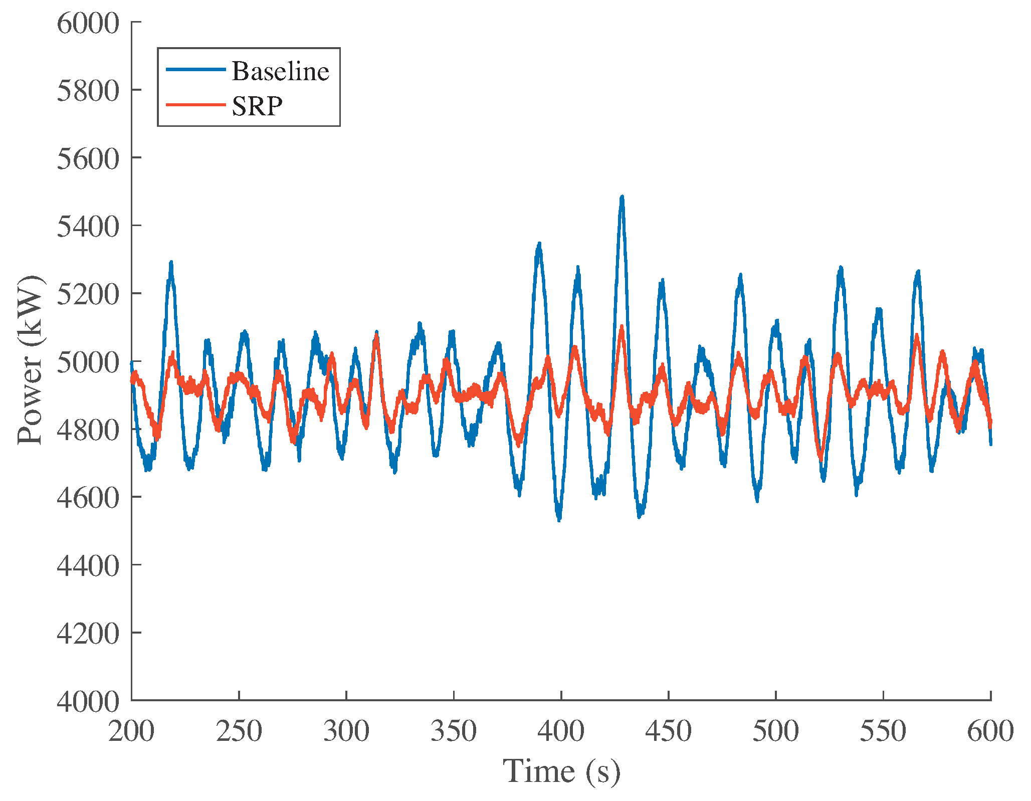
Figure 6.
Electric power index, .

Figure 7.
Side-to-side acceleration at the tower top, .
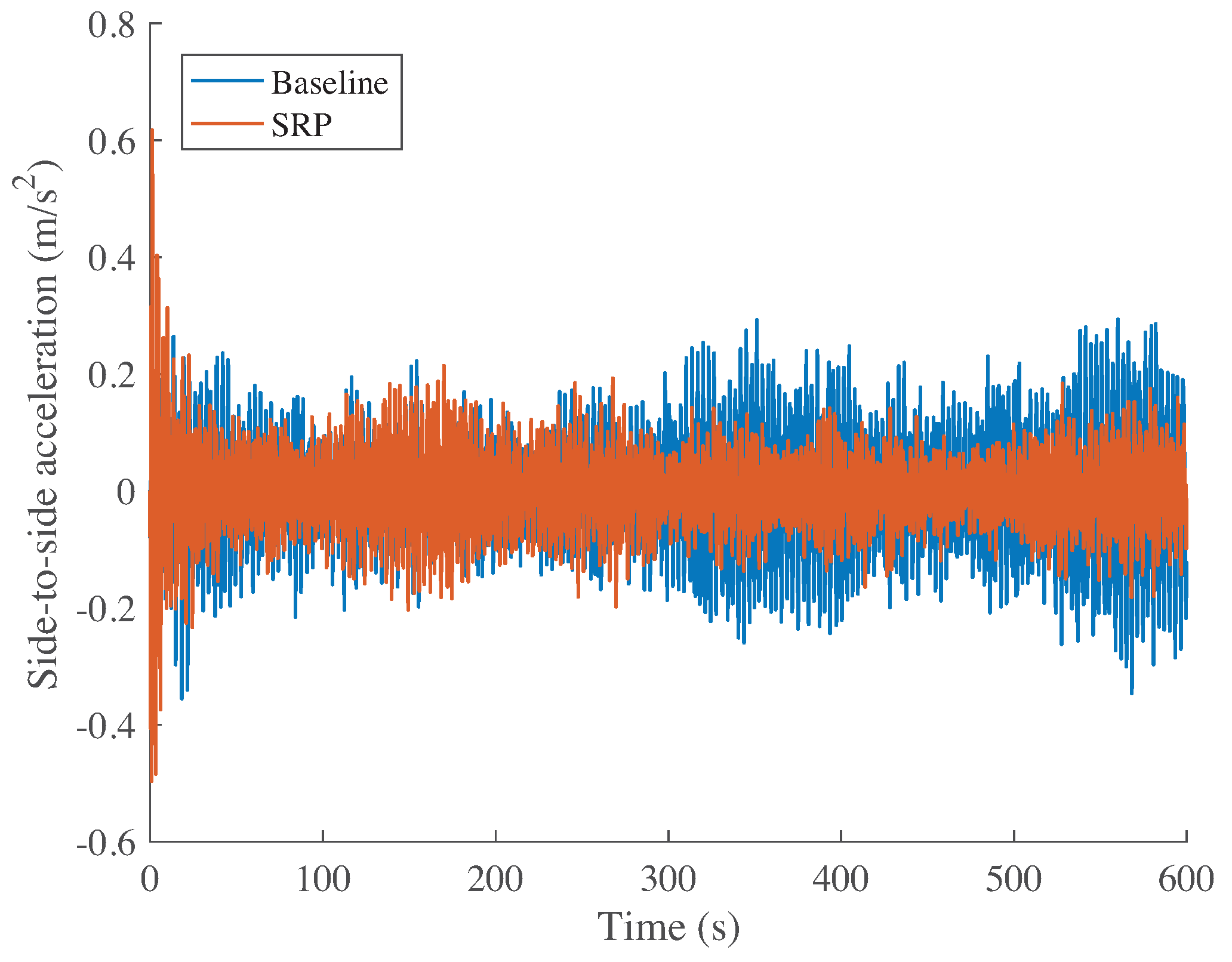
Figure 8.
Side-to-side acceleration index, .

Figure 9.
Fore-aft acceleration at the tower top, .

Figure 10.
Fore-aft acceleration index, .

Figure 11.
Pitch control signal, .
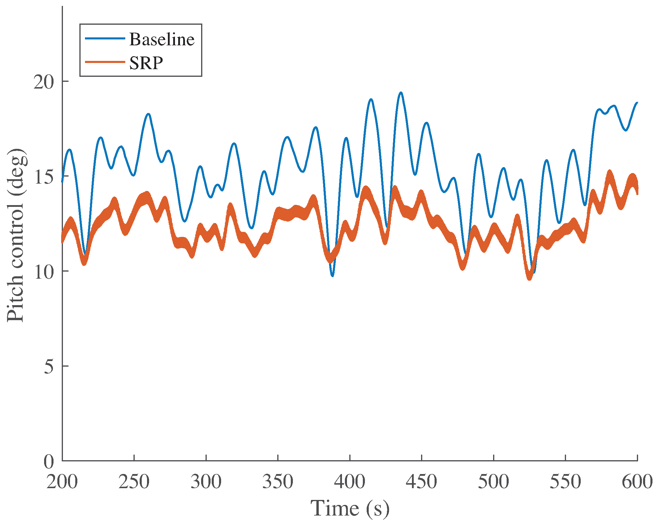
Figure 12.
Detail of the pitch control signal, , between 365 s and 375 s.
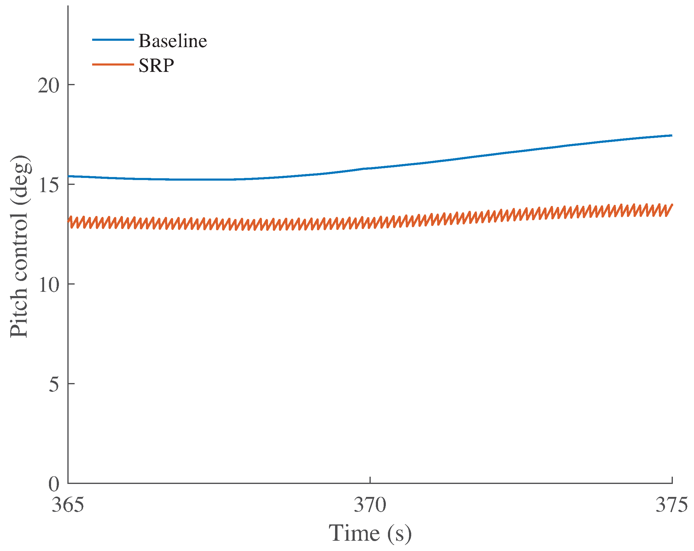
Figure 13.
Real pitch actuator signal, .

Figure 14.
Generator speed, .

Figure 15.
Generator torque control, .

Figure 16.
Platform rotational (top) and translational (bottom) data.
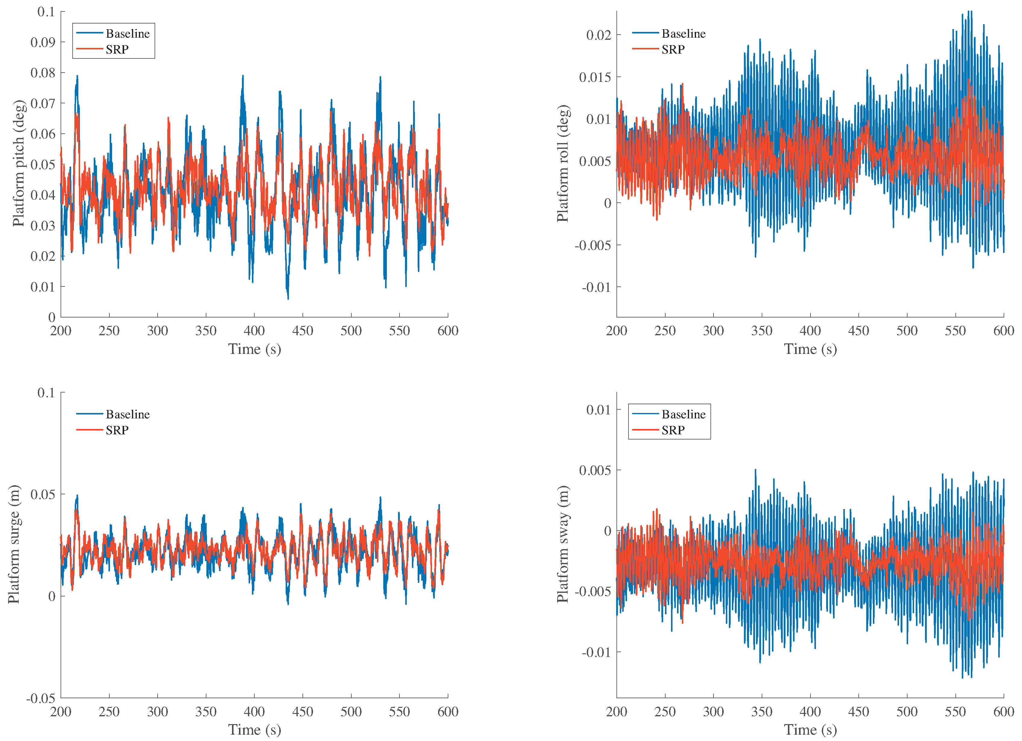
Figure 17.
Tower top (top) and tower base (bottom) shear force.

Table 1.
Comparison of control methods in the full-load region of operation [17].
Table 1.
Comparison of control methods in the full-load region of operation [17].
| Control Strategy | References | Gain | Description |
|---|---|---|---|
| PI-controller (gain scheduling) | [4,18] | Variable | Single input single output (SISO) controller simple to design and robust. |
| Linear quadratic Gaussian (LQG) | [19,20] | Fixed | Need to design observers to reconstruct unknown states. |
| Fuzzy logic control (FLC) | [21,22] | Fixed | Uncertainty modeling and treatment of qualitative magnitudes not properly described by binary concepts. |
| Sliding mode control (SMC) | [9,23] | Fixed | Robustness against system uncertainties and perturbations. |
| Model predictive control (MPC) | [7,24,25] | Variable | Input and output constraints handling, as well as on-line optimization. |
Table 2.
Main data of the offshore NREL 5-MW wind turbine [4].
Table 2.
Main data of the offshore NREL 5-MW wind turbine [4].
| Property | Value | Unit |
|---|---|---|
| Nominal Power () | 5 | MW |
| Blade number | 3 | - |
| Blade pitch angle range () | [0, 90] | deg |
| Maximum blade pitch angle rate () | 8 | deg/s |
| Rotor diameter | 126 | m |
| Hub height | 90 | m |
| Cut-in wind speed | 3 | m/s |
| Rated wind speed | 11.4 | m/s |
| Cut-out wind speed | 25 | m/s |
| Nominal generator speed () | 1173.7 | rpm |
| Nominal torque () | 40,681.5 | Nm |
| Generator torque range () | [0, 47,402.91] | Nm |
| Maximum generator torque rate () | 15,000 | Nm |
| Gearbox ratio | 97 | - |
| Generator efficiency () | 98 | % |
Table 3.
Simulated sensors and their associated noise power [17].
Table 3.
Simulated sensors and their associated noise power [17].
| Sensor type | Noise Power | Unit |
|---|---|---|
| Generator speed | m/s | |
| Pitch angle of i-th blade | deg |
© 2017 by the authors. Licensee MDPI, Basel, Switzerland. This article is an open access article distributed under the terms and conditions of the Creative Commons Attribution (CC BY) license (http://creativecommons.org/licenses/by/4.0/).
Share and Cite
MDPI and ACS Style
Vidal, Y.; Acho, L.; Cifre, I.; Garcia, À.; Pozo, F.; Rodellar, J. Wind Turbine Synchronous Reset Pitch Control. Energies 2017, 10, 770. https://doi.org/10.3390/en10060770
AMA Style
Vidal Y, Acho L, Cifre I, Garcia À, Pozo F, Rodellar J. Wind Turbine Synchronous Reset Pitch Control. Energies. 2017; 10(6):770. https://doi.org/10.3390/en10060770
Chicago/Turabian StyleVidal, Yolanda, Leonardo Acho, Ignasi Cifre, Àlex Garcia, Francesc Pozo, and José Rodellar. 2017. "Wind Turbine Synchronous Reset Pitch Control" Energies 10, no. 6: 770. https://doi.org/10.3390/en10060770
Note that from the first issue of 2016, this journal uses article numbers instead of page numbers. See further details here.