1. Introduction
Direct matrix converters (DMCs) are alternative power converters to DC-link back-to-back connected inverter-rectifier with capacitive energy storage. Therefore, DMCs can be advantageously used in unified power flow controllers (UPFCs). UPFCs emerged in the 1990s by L. Gyugyi as the most versatile FACTS (Flexible AC Transmission Systems) equipment [
1,
2]. FACTS technology uses power electronic devices—namely power semiconductors—with turn-off capability associated to their firing circuits and modern control techniques to enforce the active and reactive power in electrical systems. These power controllers work in real time to regulate the energy transit in the transmission lines up to its thermal limits [
3].
The UPFC with a classic topology, based on two AC-DC converters back to back connected through a common DC link, needs a large high-voltage DC storage capacitor bank to allow shunt and series compensation and bidirectional power flow [
4,
5,
6]. The UPFC controls some line parameters (such as impedance, bus voltage, voltage angle) guaranteeing fast, dynamic performance of the power transmission network and ensuring a reliable and precise control of both line active,
P, and reactive,
Q, power flow [
6,
7,
8].
Several research works with UPFC show conventional control methods based on power systems with linearized models, valid around an operating point, whose dynamic control and performance evaluation are presented in [
9,
10,
11,
12]. However, these control methods present poor dynamic responses and/or undesired active-reactive power coupling. Improved approaches are based on nonlinear controllers, allowing a better tuning of linear controller parameters, and have the capability to adapt to the continuously changing power system dynamics [
13,
14,
15]. In [
14], nonlinear robust direct power controllers allow dynamic response improvement based on sliding mode control techniques to select adequate space vectors to control active and reactive power in real time.
In recent years, alternative UPFC topologies have emerged based on the direct three phase AC-AC matrix converter [
11,
12,
13,
14,
15,
16]. This power converter eliminates the DC link capacitors, thus reducing cost, size, and maintenance, while increasing reliability and lifetime. The DMC processes electrical energy directly needing almost no energy storage, allows bidirectional power flow, guarantees near sinusoidal input and output currents, and controls the voltage’s amplitude and frequency at an adjustable power factor [
17,
18]. These AC/AC converters guarantee that the active power exchanged on the UPFC series connection is always supplied/absorbed by the shunt connection, and still have the capability to allow independent reactive control on the UPFC shunt and series converter sides. However, as there is almost no DMC stored energy, input and output powers are strongly coupled, hardening the control design.
The main contribution of this paper is, therefore, a new real-time vector modulation and control for the DMC-UPFC. This control method uses an algorithm based on the power system model equations and the direct method (2nd method) of Lyapunov to guarantee asymptotic stability. The control strategy is based on the desired references for active,
P, and reactive,
Q, power flow and uses a cost functional to choose the converter output vector closest to the optimum [
19] considering
P and
Q requirements. The power controllers choose the converter output vector by minimizing the distance between the virtual control vector and all available converter vectors. This digital control method allows a significant reduction in the computing time of the digital signal processing (DSP) unit in many industrial applications [
20].
A theoretical analysis of the new real time Lyapunov-based controller, applied to the DMC-UPFC with input filter, is presented (
Section 3). Dynamic and steady-state performance of the
P and
Q power control method is evaluated and discussed using detailed simulations and experimental implementation (
Section 4 and
Section 5). Results show a controller insensitive to power system non-linearity and active and reactive power control with zero error tracking and fast response times (
Section 6). Results also show a low total harmonic distortion (THD) in the output voltages and currents ensuring a good performance of this controller in power quality applications. The controllers are insensitive to power system non-linearity, presenting very low sensitivity to cross-coupling effects.
2. Modeling of the UPFC Power System
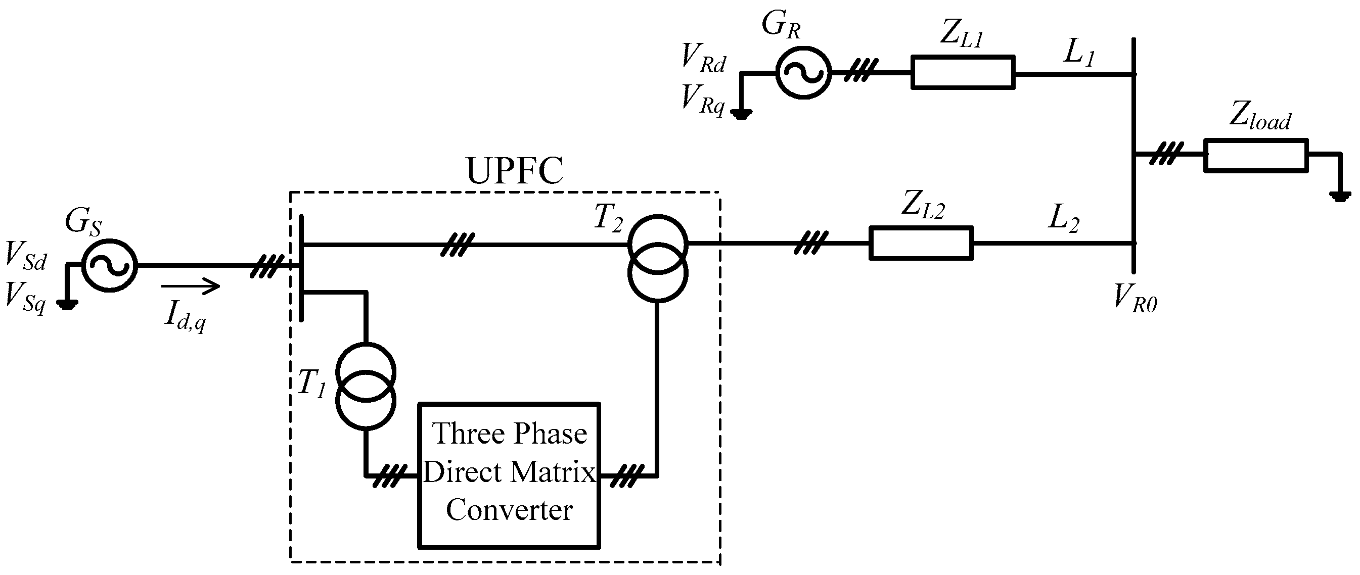
The proposed power system model of the DMC operating as a UPFC is presented in the simplified scheme of
Figure 1.
In this power transmission network,
VS and
VR are the sending-end and receiving-end voltages, respectively, of
GS and
GR generators feeding load
Zload. The DMC is connected to the transmission line 2 through shunt and series coupling transformers, respectively
T1 and
T2. Also, as shown in
Figure 1,
ZL1 and
ZL2 are the impedances of the transmission lines 1 and 2, respectively, represented as a series inductance and resistance.
2.1. UPFC Power System Dynamic Model
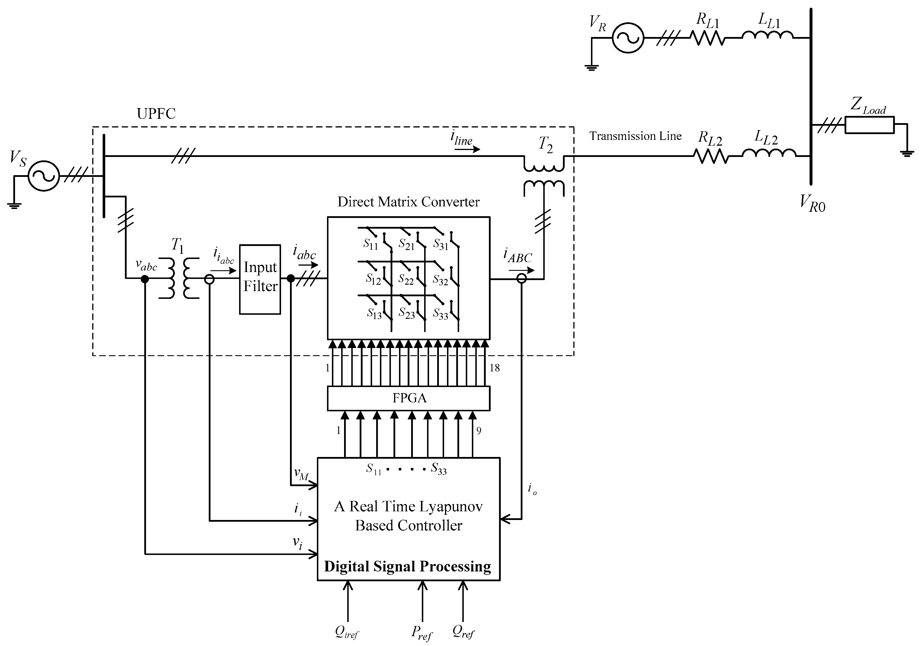
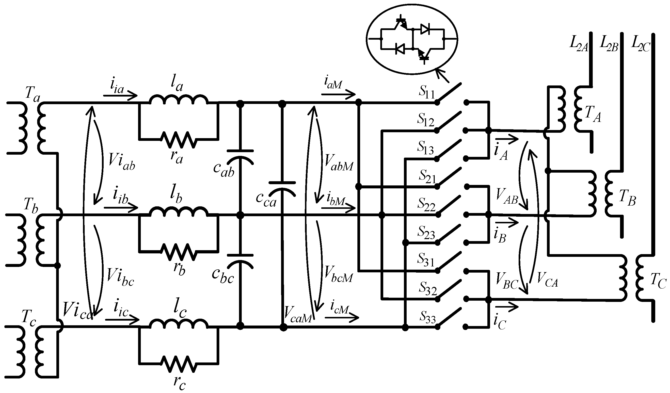
Figure 2 shows the connection diagram of the DMC-UPFC system to the transmission line. This diagram includes a three-phase
LCR input low pass filter to re-establish a voltage-source boundary to the DMC input and to enable smoother input currents. A three-phase shunt input transformer (
Ta,
Tb,
Tc), a three-phase series output transformer (
TA,
TB,
TC) and a three-phase DMC are also included.
To design DMC-UPFC decoupled active and reactive power controllers, the dynamic Equation (1) is considered. This equation represents the active and reactive power of sending end generator
GS, in
dq coordinates [
21].
where
VSd,
VSq are the mains voltage components, and
Id,
Iq the line currents, both in
dq coordinates (
Figure 1).
Choosing a
dq rotating reference frame so that the mains voltage (
VSq) is equal to zero,
P and
Q will be given by Equation (2).
The control vector components to ensure convergence of the power references values are obtained considering the time derivative of Equation (3), assuming constant
VSd.
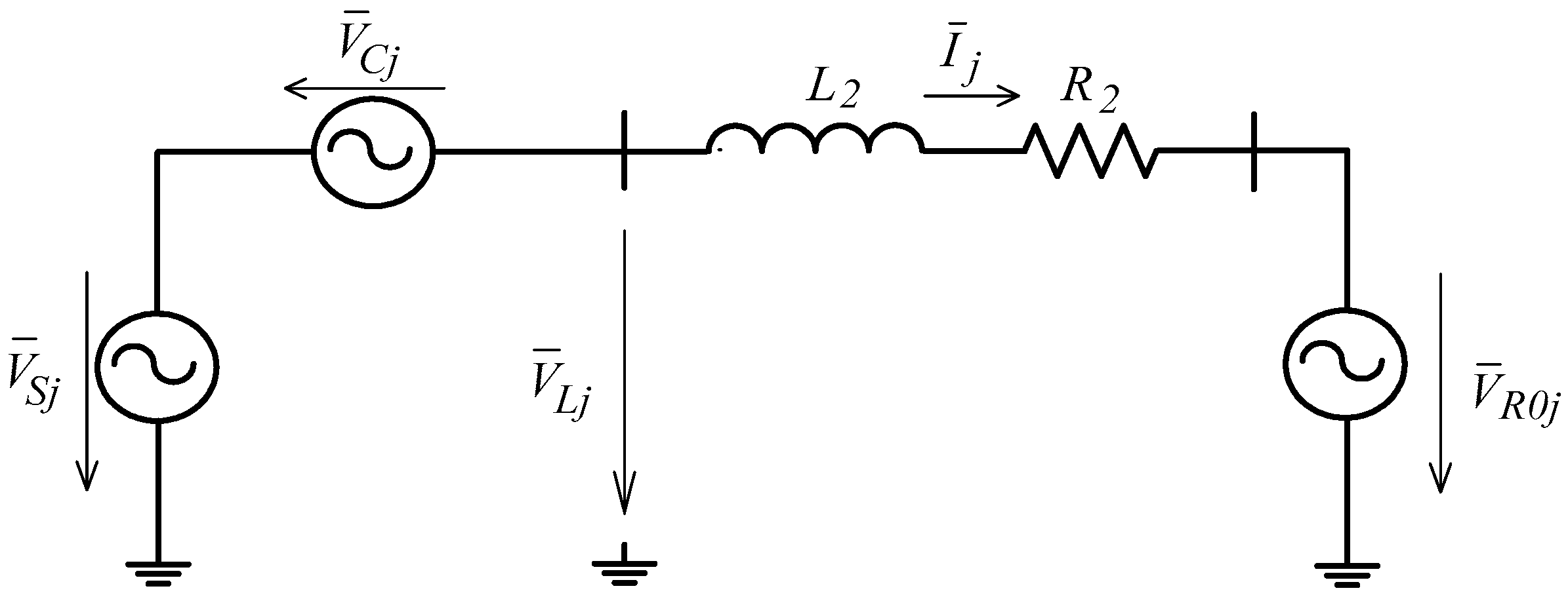
Considering a symmetrical and balanced three-phase system, an equivalent per-phase model of a DMC-UPFC transmission system, shown in
Figure 3, is obtained, where the voltage sources, the coupling transformers and the DMC are all considered ideal. Based on this simplified circuit, the dynamics of three-phase currents
ij in the transmission line is:
Applying the Kirchhoff laws to the equivalent circuit gives the equations of the AC line currents in
dq coordinates:
In (5), Thevenin equivalent inductance and resistance (L2 and R2) are estimated by L2 = X2/ω, R2 = RL2 + RL1||RZload.
Substituting line currents (5) in (3) and simplifying the result, Equation (6) is obtained:
From these dynamics, it can be seen that P and Q can be controlled by VCd and VCq, being VR0d and VR0q system disturbances.
2.2. Direct Matrix Converter Model
To apply a closed-loop space-vector technique, the ideal three-phase direct matrix converter may be considered as an array of nine bi-directional switches, Skj. These switches have turn-on and turn-off capability, allowing the connection of each one of three output phases directly to a given three-phase input voltage.
Considering also ideal power semiconductors, each DMC bi-directional switch
Skj (
k,
j ∈ {1, 2, 3}) can assume two possible states: “
Skj = 1” (switch closed) or “
Skj = 0” (switch opened), being the nine DMC switches represented as a 3 × 3 matrix (7). Taking into account circuit topology restrictions, no input phase short-circuits and no open output phases, there are only 27 possible switching combinations [
14].
According to
Figure 2 the output and input voltages are related by matrix
S, being
. Then, it is necessary to represent the output voltages and the input currents yielding 27 switching patterns, as time variant vectors in
αβ coordinates [
14]. The relationship between input phase currents and output phase currents depends on the transposition of matrix
S:
.
3. DMC-UPFC Lyapunov-Based Control
The proposed control strategy based on the direct method of Lyapunov stability starts by defining a positive definite Lyapunov candidate function
VX =
eX2/2, where
eX is the tracking error of the
X variable,
eX =
XRef −
X. To ensure a globally asymptotically-stable control solution from Lyapunov’s direct method of stability [
22], the time derivative
of the positive-definite Lyapunov function
VX must be globally negative-definite
, or
. This can be achieved by imposing an error dynamic such as:
where
kX is a positive definite constant, resulting in
. Equation (8) ensures asymptotic stability, as the
eX error tends to zero with time constant 1/
kX, and robustness as the error dynamic in (8) is independent of the system parameters.
3.1. Active and Reactive Power Control
The control objective is to track the power references
PRef,
QRef, so that
eX = [
eP,
eQ]
T, the tracking errors (or deviations) being
eP =
PRef −
P and
eQ =
QRef −
Q:
To guarantee no cross-coupling between
P and
Q power controllers, fast response times and asymptotic stability, Lyapunov candidate functions are defined as
VP =
eP2/2,
VQ =
eQ2/2. Therefore, the controller must enforce:
This can be accomplished if it is considered:
where
kP,
kQ are positive definite constants. Replacing the
eP,
eQ time derivates using (6), Equation (12) is received:
Solving Equation (12) for
VCdRef and
VCqRef the DMC controller must impose the output voltages
VCdRef and
VCqRef.
This equation defines the reference values VCdRef, VCqRef that must be injected in the line by the series transformer of the space-vector PWM controlled DMC.
3.2. Input Reactive Power Control
Applying Blondel-Park transformation to the input filter state variables presented in
Figure 3 and neglecting the effects of the damping resistors, Equation (14) can be written, where
Vid,
Viq,
iid,
iiq represent input voltages and input currents in
dq components (at the shunt transformer secondary), and
VdM,
VqM,
idM,
iqM are DMC voltages and input currents in
dq components, respectively,
This transformation guarantees all input variables of the matrix converter are time invariant in the rotating reference frame.
The control objective is to have
Qi =
QiRef = 0. The control input is
and the output is
, as
at constant
. Defining the tracking error
, to guarantee Lyapunov asymptotic stability in this 2nd order system, the controller must enforce an exponentially stable error dynamics tending to zero such as
, where
k1 and
k2 are positive definite constants. Therefore:
Solving (14) for
, Equation (16) is obtained:
Simplifying (16) and replacing the value of
in (15), Equation (17) is obtained:
where
iqMRef is the value of
iqM (control input) that satisfies (15). Solving (17) for the reference value
iqMRef of the
q component of the matrix current
iqM, Equation (18) is obtained:
Equations (13) and (18) require distinct space-vectors to impose
VCdRef,
VCqRef and
iqMRef, as discussed in
Section 2.2. The optimum space-vector is computed in the next section by minimizing a cost functional of the reference voltages and current errors.
3.3. Optimum Space-Vector
A weighted cost functional of squared tracking errors is used to select in real time the optimum space-vector (one out of the 27 possible switching combinations) which should be applied to the DMC operated as UPFC in the following sampling period.
The vector selection strategy minimizes the cost functional given in (19).
where
,
and
, represent the errors between the references and values obtained with each switching combination, and
,
and
are the respective weights.
In each sampling time ts, the real-time modulation control method first calculates the reference components, VCdRef(ts), VCqRef(ts) and iqMRef(ts) given in (13) and (18). Then, the weighted cost functional (19) is evaluated for each one of the 27 matrix vectors to select the one presenting the minimum value of the cost functional.
4. Implementation of DMC-UPFC Controller
The implementation scheme of the proposed DMC-UPFC controller is presented in the block diagram of
Figure 4. In this scheme, the control of the instantaneous
P and
Q powers requires the measurement of the instantaneous output voltages and currents. The control of the matrix input reactive power requires the measurement of the input currents, and the measurement of the mains and capacitor voltages.
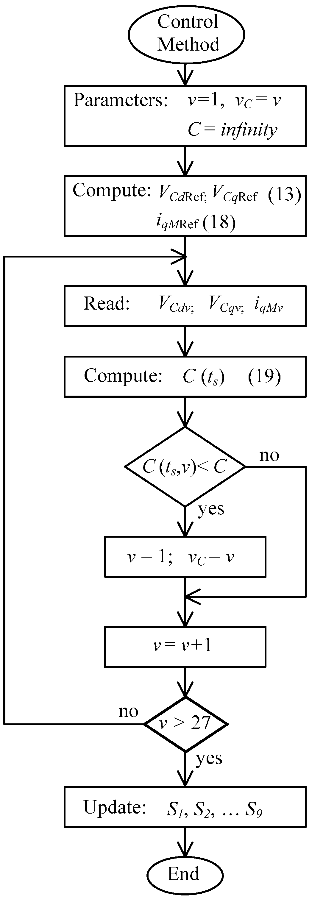
The real time Lyapunov-based controller (
Figure 4) algorithm, implemented in a digital signal processor, is presented in the flowchart in
Figure 5. As shown in the diagram, the control method main loop calculates the values of
VCdRef(
ts),
VCqRef(
ts) and
iqMRef(
ts) once, while the cost functional,
C(
ts), is evaluated 27 times to find the vector with components
VCd(
ts),
VCq(
ts) and
iqM(
ts) that minimizes the weighted cost functional. This selects the space-vector which minimizes the cost functional, and is applied to the DMC-UPFC in the following sampling time (
ts + Δ
T).
Relative to predictive controllers [
19], the control process proposed here reduces the microprocessor computational effort.
5. Simulation and Experimental Evaluation
This section presents simulation and experimental results to evaluate the performance of the proposed control method. First, using detailed simulation models for the three-phase direct matrix converter, series and shunt transformers, sources, transmission lines, loads and real-time Lyapunov controller algorithm, the DMC-UPFC is simulated using the MATLAB/Simulink SimPowerSystems toolbox. Matrix converter semiconductors were simulated as SimPowerSystems switches with appropriate snubbers.
In order to validate the simulation results with experimental results, a low-power prototype DMC was built [
23], using three semiconductor modules from DANFOSS, each one with six 1200 V, 25 A insulated-gate bipolar transistors (IGBT) with anti-parallel diodes, in a common collector arrangement, driven by optical isolated drives (TLP250). The second order input filter component values are:
l = 4.2 mH,
C = 6.6 µF,
r = 25 Ω. This prototype was connected to the laboratory low-voltage network operating as a UPFC, (
Figure 4) using three-phase transformers
T1,
T2 (2 kVA transformers with voltage ratio 220/115 V and 66.5/66.5 V, respectively). Voltage sensors were used to measure the voltages (LEM LV 25-P), while current sensors were used to measure the DMC currents (LEM LA25NP).
To carry out real-time control of the power in the transmission lines, a real-time DSP board (DS1103 model of dSPACE) with the proposed control algorithm was used to select the suitable vector at every sampling time. The DS1103 was able to execute the vector modulation, control algorithm, and output the 9 DMC bidirectional switch control signals at a sustained sampling time (
Ts) of 18 μs. This sampling time is suited to switching the DMC at frequencies around 5 kHz, but is not enough to guarantee safe commutation between the DMC bidirectional switches, as this requires much faster changing signals. Therefore, to ensure safe commutation, the four-step output current commutation strategy was used [
18], implemented in a field-programmable gate array (FPGA) using a Xilinx (Virtex 5) board, as represented in
Figure 4.
Experimental results were obtained considering that the input phase-to-phase DMC voltage equalled 120 VRMS; the load power equalled 1.5 kW (1 pu), the transmission lines 1 and 2 were emulated by inductances LL1 = 12 mH, LL2 = 15 mH and series resistances RL1 = RL2 = 0.2 Ω, respectively.
Also, experimental and simulation results for the
P and
Q power UPFC controller were obtained from the step response to changes in
PRef and
QRef references (Δ
PRef and Δ
QRef, respectively).
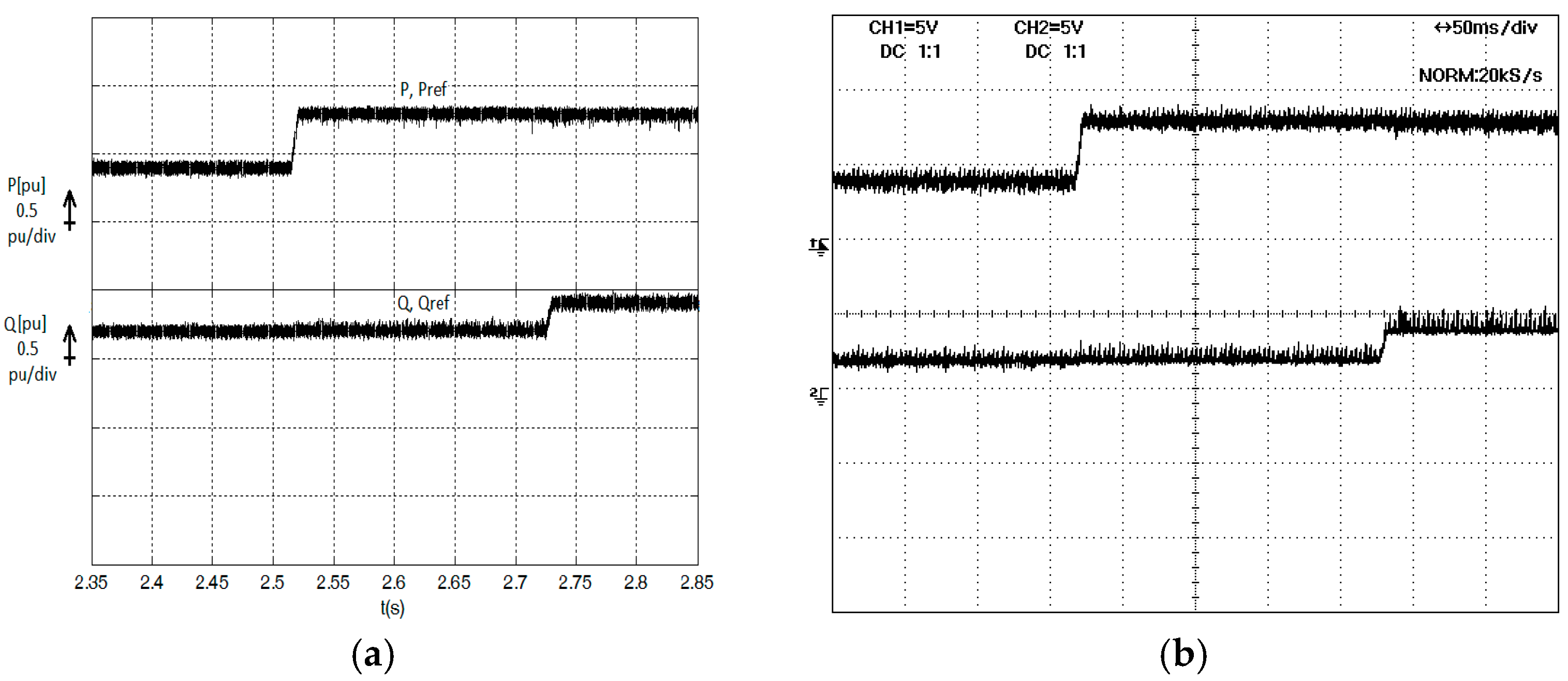
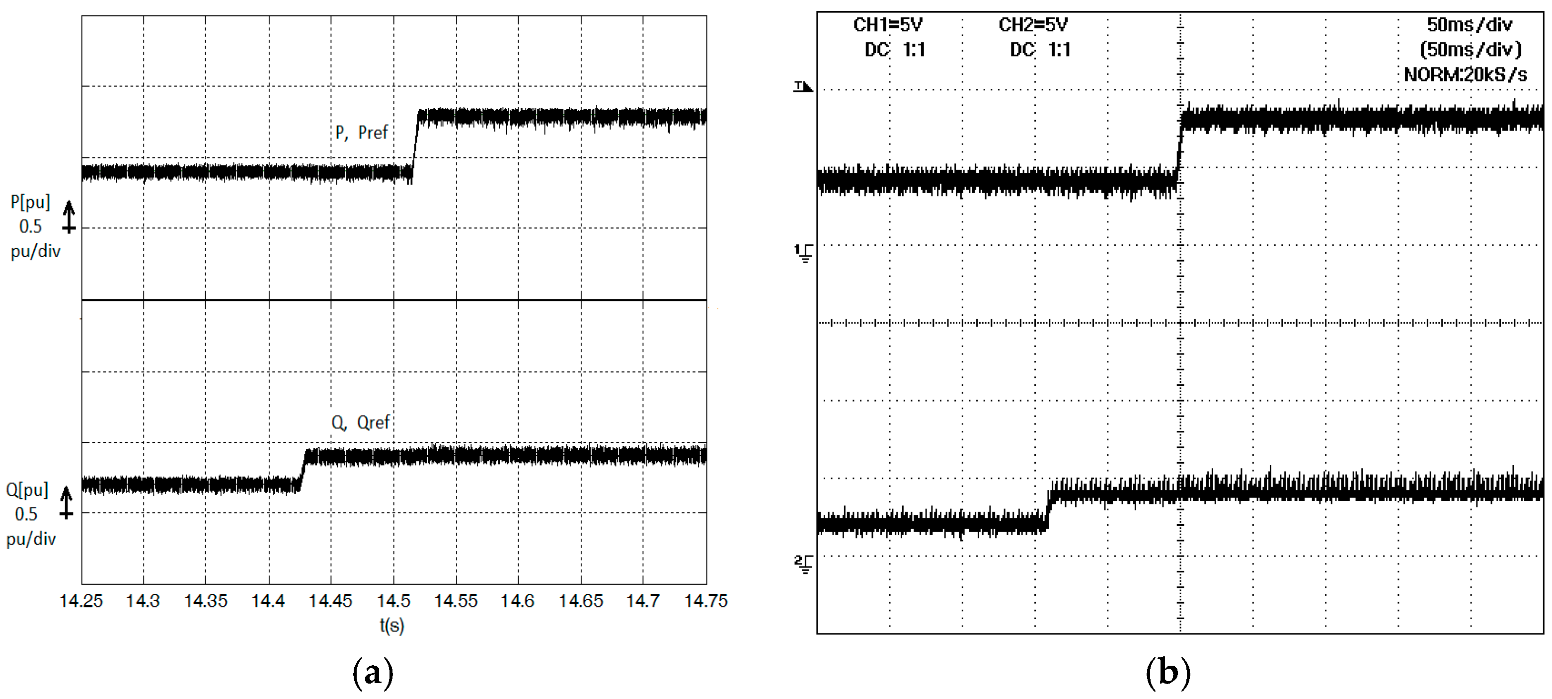
Figure 6a,b show, respectively, simulation and experimental results for the proposed controller, considering
P and
Q power step responses to Δ
PRef = +0.4 pu and Δ
QRef = +0.2 pu, with initial reference values
PRef = 0.4 pu,
QRef = 0.2 pu.
Both results show clearly that there is no cross-coupling between active and reactive power, being both independently controlled, and showing a fast response with a small ripple in steady state. The results of
Figure 7a,b are simulation and experimental results, respectively, for the proposed control method, when the same initial conditions as in
Figure 6 are retained, but with different time instants. Once again, these results prove the good performance of the power controller.
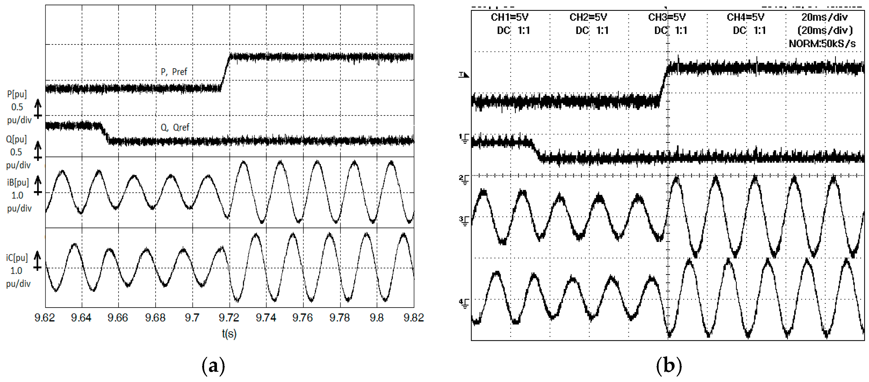
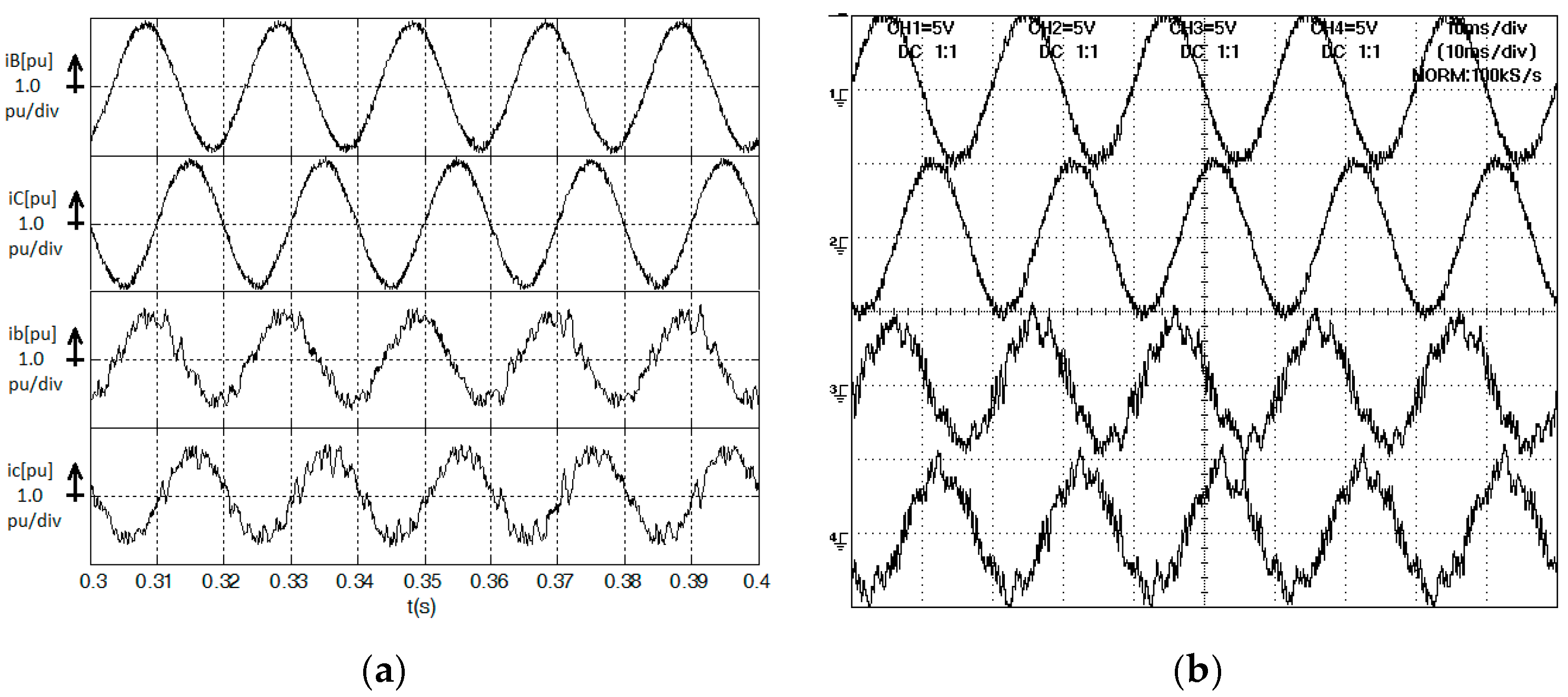
Figure 8a,b show the simulation and experimental results, respectively, of the active and reactive powers, and also the line currents, considering P and Q power step responses to Δ
PRef = +0.4 pu and Δ
QRef = −0.2 pu, when initial reference values are
PRef = 0.4 pu,
QRef = 0.2 pu. These results show no cross-coupling, steady-state errors below ripple errors, and fast response times for different changes of power references. Line currents are almost sinusoidal with small ripple content.
Results of
Figure 8b and
Figure 9a show line and input direct matrix converter currents in steady-state, for
PRef = 0.4 pu,
QRef = 0.2 pu. Line currents are almost sinusoidal with small ripple content, while matrix currents shows some ripple content as usual in DMC [
15].
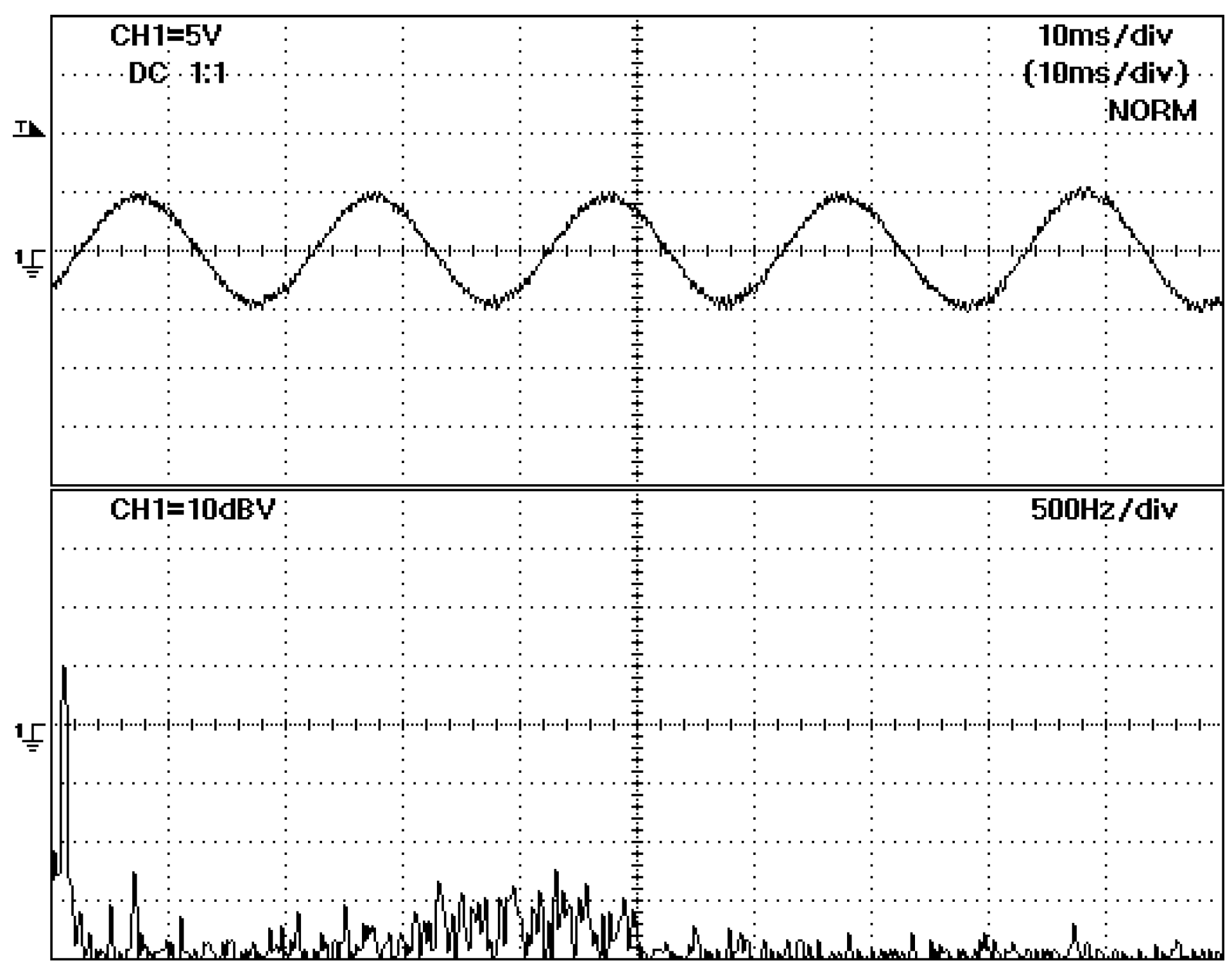
The experimental power spectral density of transmission line converter current (
Figure 10) shows that the main harmonics are nearly 35 dB below the 50-Hz fundamental.
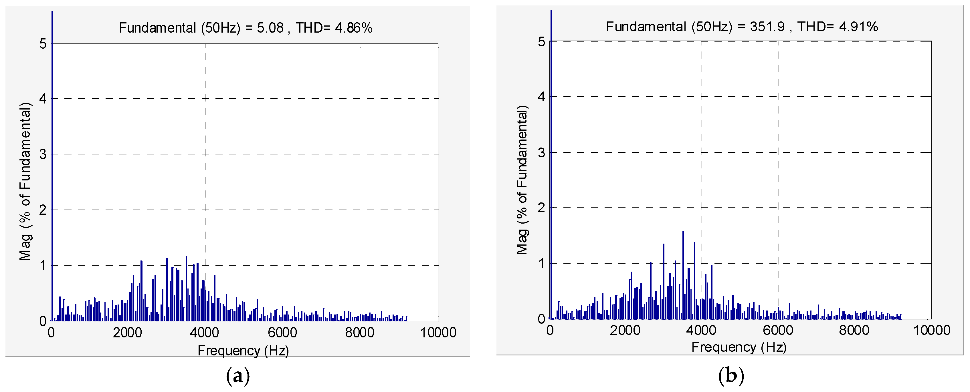
Figure 11a,b show, respectively, the harmonic spectrum of the line current and load voltage. These quantities present a low harmonic content (THD less than 5%) of 4.86% and 4.53%, respectively, which compares favourably with the improved methods proposed in [
24] to enhance power quality in matrix converters (the THD of input currents is higher than 6.29% in [
24]).
Compared to linear [
24], sliding-mode [
15], and predictive [
20] controllers, the Lyapunov controlled matrix-based UPFC presents the lowest THD of currents, even lower than linear controllers; while for cross-coupling and response times, they present better results, as do sliding-mode and predictive controllers. Concerning steady-state errors, all controllers theoretically show no steady-state errors, while the Lyapunov controller’s asymptotic stability guarantees that the controller will enforce an exponentially stable dynamic, tending to zero error, which is not guaranteed by predictive controllers.
Simulation and experimental results show that P and Q power flow can be effectively controlled using the DMC-based UPFC and the proposed power control method.
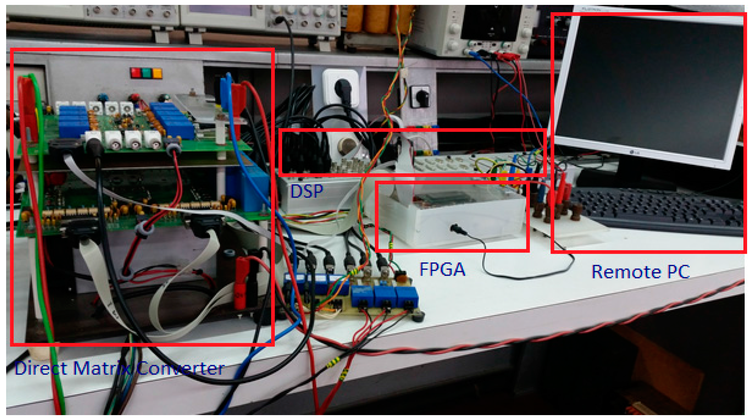
A DMC-based UPFC was implemented in the laboratory to verify the proposed power controller, as shown in
Figure 12.

