1. Introduction
Smart meters are now installed for domestic consumers in areas serviced by the Tokyo Electric Power Company and the Kansai Electric Power Company, but not for commercial consumers [
1]. These smart meters report the power consumption conditions of each domestic consumer to the electric power companies. It is natural that household electricity prices associated with high quality power consumption should be lower than those for the consumers with low quality power consumptions. Thus, in the near future, each domestic consumer will take responsibility for improving the quality of their power consumption. In Japan, single-phase three-wire distribution feeders (SPTWDFs) with pole-mounted distribution transformers (PMDTs) are used for domestic consumers.
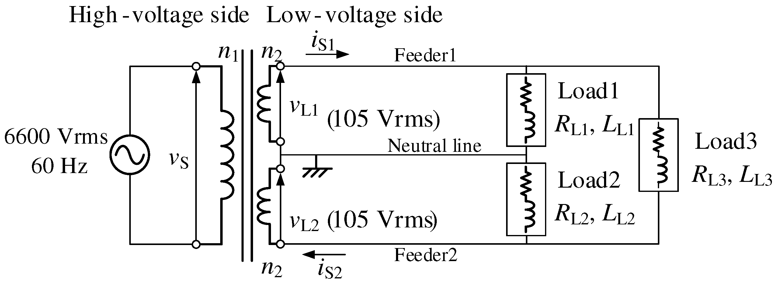
Figure 1 shows a circuit diagram of a typical SPTWDF with a PMDT. Consumer electronics in Japan are divided into two categories depending on their capacity. Large-capacity consumer electronics are connected to Feeder1 and Feeder2 as Load3, and their voltage rating is 210 Vrms. Small-capacity consumer electronics are connected to each feeder with neutral lines as Load1 and Load2, and their voltage rating is 105 Vrms. Load conditions in domestic consumers are always unbalanced. These unbalanced conditions cause the unbalanced voltage on the secondary side of the PMDTs. The secondary side source currents of the PMDTs are also unbalanced. It well known that these unbalanced source–current conditions increase losses in the PMDTs. Power companies compensate for these losses although the losses are caused by domestic consumers. There are a large number of PMDTs in Japan, so that total economic losses are great. It is also natural that domestic consumers should be responsible for the loss compensation in PMDTs.
Electric vehicles (EVs), such as the Mitsubishi i-MiEV, a five-door hatchback kei car, and the Nissan LEAF, a medium-sized five-door hatchback car, are now commercially available in Japan. The lithium-ion batteries equipped in the i-MiEV can store 16 kWh, whereas the maximum stored power in the LEAF is 30 kWh. These EVs are highly mobile with the stored power. With this mobility, the concept of injecting power stored in EVs into the grid or home (Vehicle-to-Grid, and Vehicle-to-Home) was proposed [
2,
3,
4,
5]. A pulse-width modulated (PWM) rectifier with a bidirectional DC-DC converter was used with a photovoltaic (PV) system [
6], and control and power management of the PV system were discussed. Various studies analyzing the value and potential impact on the utility grid were reported [
7,
8,
9]. The analysis of the reactive power operation in a charger was described in detail. The operation modes of the proposed battery charger were divided into quadrants based on the active and reactive powers on the AC side. In addition, the control method, DC capacitor design, ac inductor design, and loss evaluation were discussed. If the charger in [
7,
8,
9] is connected to SPTWDFs, perfect reactive power compensation for each feeder with a unity power factor cannot be achieved on the low-voltage side. However, unbalanced conditions remain on the secondary side of the PMDT. Balancing the currents on the two feeders is effective for balancing the feeder voltages and reducing the losses.
As described above, domestic consumers should be responsible for improving the quality of their power consumption in the near future with the smart meters, which are used to report the quality of their power consumption of each domestic consumer to the electric power companies. Thus, the present authors previously proposed a smart charger for EVs with a power quality compensator in SPTWDFs [
10].
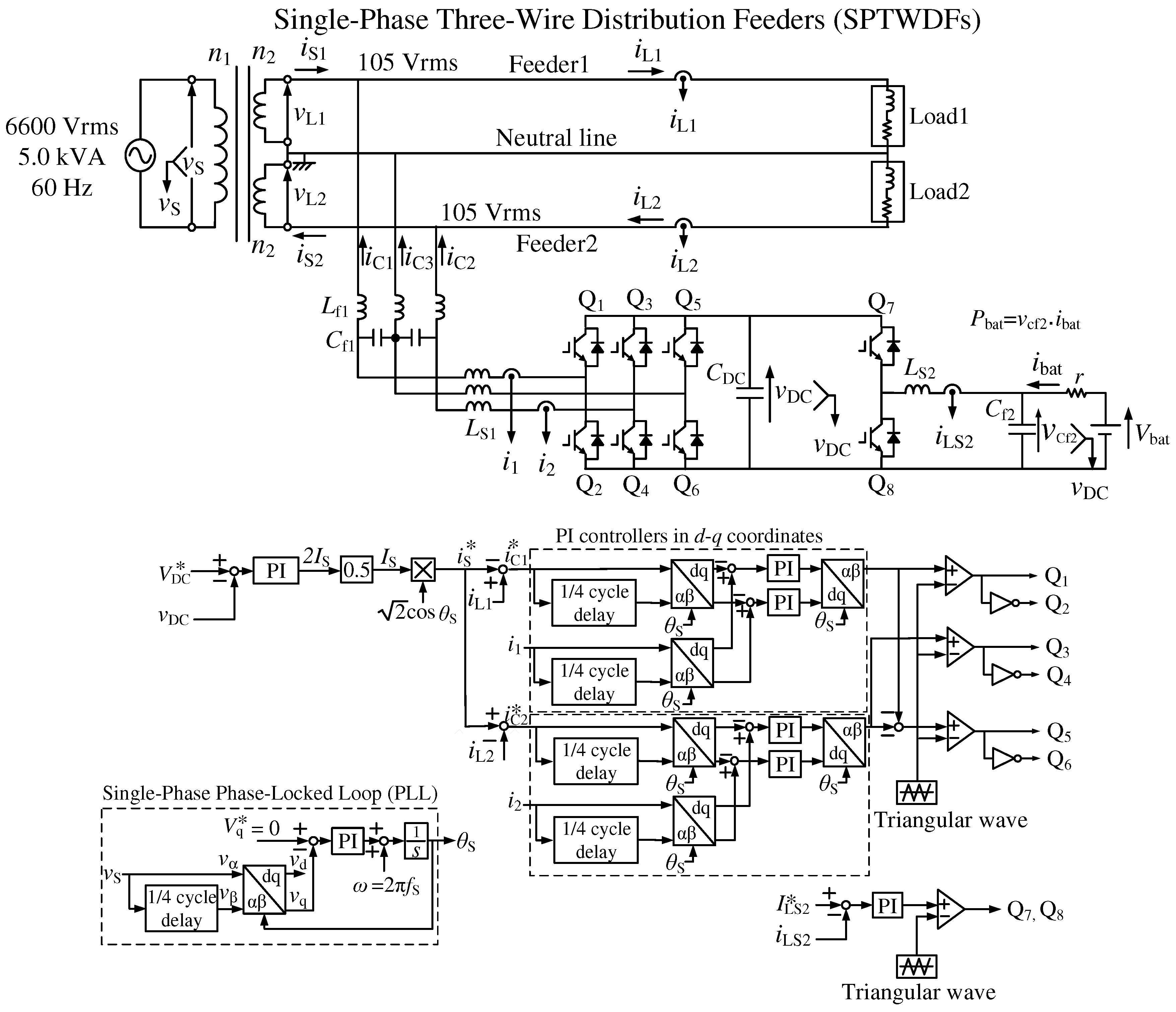
Figure 2 shows a power circuit diagram of the previously proposed smart charger for EVs with a power quality compensator [
10]. The proposed smart charger consists of four-leg insulated-gate bipolar transistors (IGBTs). The first leg and second leg are connected to Feeder1 and Feeder2, respectively. The third leg is connected to the neutral line. This is an advantage of the proposed smart charger as compared to the chargers proposed in [
7,
8,
9]. This PWM rectifier can compensate reactive and unbalanced active currents in SPTWDFs by canceling the neutral line current. The fourth leg is used as a bidirectional DC-DC converter for both the battery-charging and -discharging operations in EVs. The LCL filters with two capacitors effectively eliminate the switching ripples of charger currents
,
, and
because the third leg is connected to the neutral line, which is grounded. For the control strategy of the three-leg PWM rectifier in
Figure 2, only a constant DC-capacitor voltage control (CDCVC), which is commonly used in active power-line conditioners, is used. This simple control algorithm achieves balanced source currents with a unity power factor. Simulation and experimental results demonstrated that balanced source currents with a unity power factor are obtained on the source side of SPTWDFs during both the battery-charging and discharging operations in EVs.
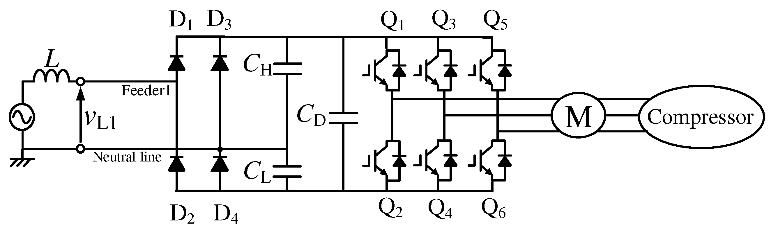
As described before, large-capacity consumer electronics are connected to Feeder1 and Feeder2, and their voltage rating is 210 Vrms. Typical large-capacity consumer electronics are air conditioners for large rooms and induction heating (IH) cookers. Small-capacity consumer electronics are connected to each feeders with a neutral line, and their voltage rating is 105 Vrms. Typical small-capacity consumer electronics include air conditioners for small rooms, refrigerators, personal computers, liquid crystal display televisions, and illuminators. Thus, diode rectifiers are used in modern consumer electronics to convert AC voltage to DC voltage. For example,
Figure 3 shows a power circuit diagram of the inverter, which is used in an air conditioner for small rooms [
11]. The air conditioner for small rooms is connected to each feeder with a neutral line, and their voltage rating is 105 Vrms. A three-phase variable-voltage variable-frequency inverter is used to control a three-phase AC motor, which drives the compressor in modern air conditioners. A single-phase voltage-doubler rectifier is included in the inverter circuit in
Figure 3. The air conditioner for small rooms is connected to each feeder with a neutral line, and their voltage rating is 105 Vrms. Harmonic currents are produced, and injected to the source. Single-phase diode rectifiers are also included in IH cookers and air conditioners for large rooms. Thus, these consumer electronics produce harmonic currents and inject them to the source. However, only linear loads were considered in [
10], as shown in
Figure 2 by Load1 and Load2. Thus, discussing the compensation performances for harmonic currents using the CDCVC-based strategy of smart charger remains an issue for further study.
This paper presents reactive, unbalanced active, and harmonic current compensation using the CDCVC-based strategy for smart charger in SPTWDFs under distorted load current conditions. The basic principle of the CDCVC-based strategy for smart chargers and the instantaneous power flowing into a smart charger are discussed in detail. This instantaneous power flowing into the smart charger shows that the previously proposed CDCVC-based strategy can compensate fundamental reactive, unbalanced active, and harmonic currents on the source side. The balanced and sinusoidal source currents with a unity power factor are achieved using only the CDCVC-based strategy, which is commonly used in active power-line conditioners. A digital computer simulation is implemented to confirm the validity and high practicability of the CDCVC-based strategy under unbalanced and distorted load current conditions. Simulation results demonstrate that sinusoidal and balanced source currents with a unity power factor are achieved on the secondary side of the PMDT during both the battery-charging and -discharging operations in EVs, compensating the reactive, unbalanced active, and harmonic currents. Simulation results also demonstrate that sinusoidal and balanced source currents with a unity power factor are achieved even though EVs are not connected to the smart charger.
2. Constant DC-Capacitor Voltage-Control-Based Strategy for Smart Chargers
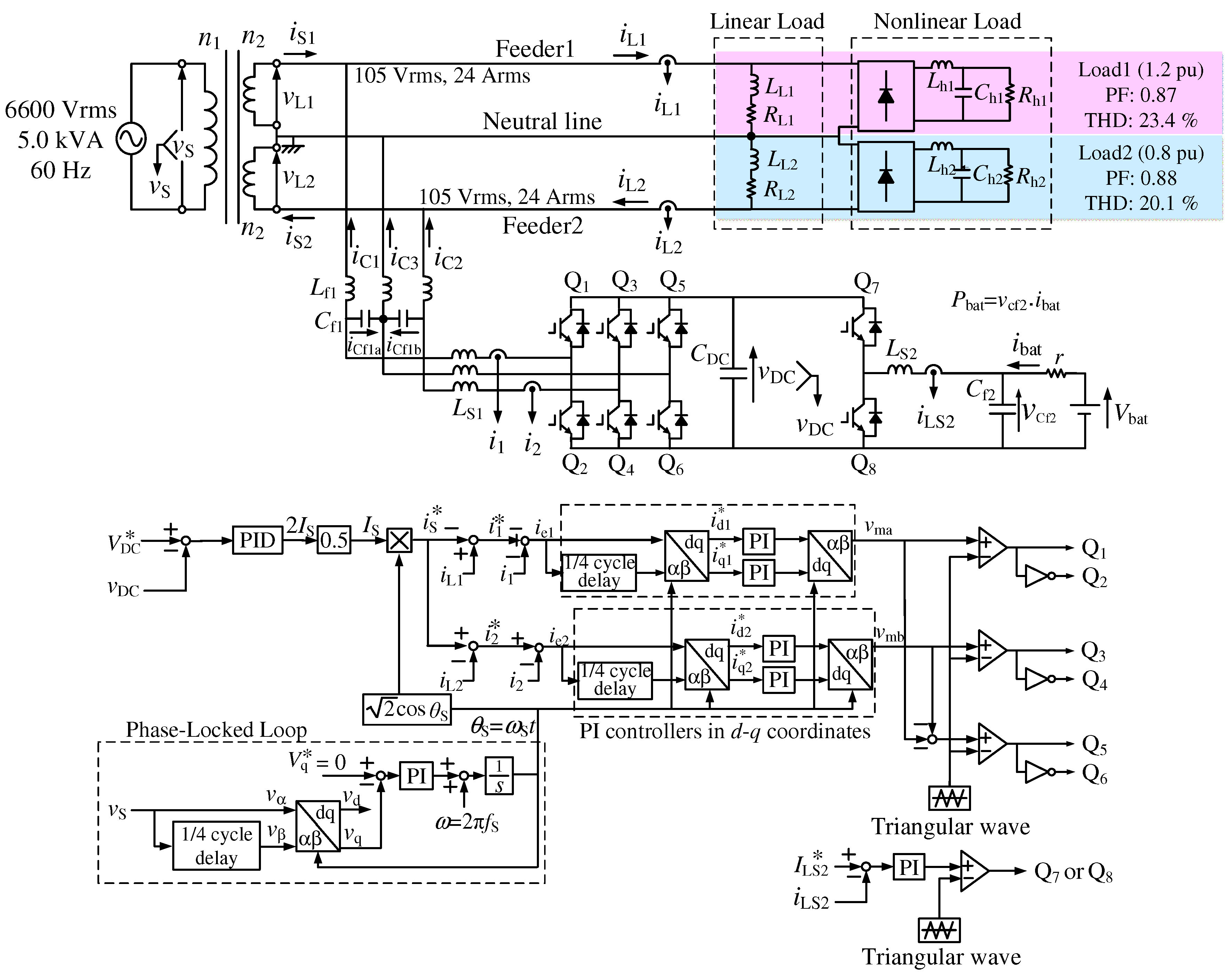
Figure 4 shows a circuit diagram of the proposed smart charger, in which nonlinear loads are connected in parallel to the RL linear loads. The voltage rating of the PMDT is 6600 Vrms, 5.0 kVA, and 60 Hz on the primary side, and 105 Vrms on the secondary side. Thus, the current rating of Feeder1 and Feeder2 currents is 24 Arms. Diode rectifiers are included in modern consumer electronics. Thus, diode rectifiers in addition to linear loads are connected to each feeder with a neutral line. These diode rectifiers perform modern consumer electronics in SPTWDFs. The total harmonic distortion (THD) values were decided considering IEC61000-3-4 [
12]. For the battery model, an ideal DC voltage source of 360
V is also used. For the control algorithm of the three-leg PWM rectifier, the CDCVC-based strategy is used [
10]. A proportional-integral (PI) controller was used in the CDCVC block as shown in
Figure 2. In this paper, a proportional-integral-derivative (PID) controller is used to improve the response of the CDCVC-based control strategy because harmonic currents are included in addition to fundamental-reactive and -unbalanced active components of the load currents
and
. The difference between the PI controllers in
d-
q coordinates in
Figure 2 and that in
Figure 4 are explained later. The purpose of this paper is to demonstrate reactive, unbalanced active, and harmonics currents compensation of the CDCVC-based strategy of smart charger for EVs in SPTWDFs under nonlinear load conditions. Thus, ideal models for IGBTs are used. In three-phase circuits, some control strategies for these active power-line conditioners are based on instantaneous active-reactive power theory, the so-called “
theory”, which was originally proposed by Akagi et al. [
13,
14,
15,
16,
17]. The instantaneous symmetrical component theory method, the sample and hold circuit method, and the
d-
q transformation based method are also used for the calculation of the reference compensation currents [
18,
19,
20]. Single-phase
theory was proposed for single-phase active power line conditioners [
21]. In this method, the instantaneous active-reactive power calculation block is also included. On the other hand, in
Figure 4, no calculation blocks of the reactive, unbalanced active, and harmonic components of the load currents are necessary. Thus, the authors provide the simplified algorithm for smart charger. This simple control algorithm achieves balanced and sinusoidal source currents with a unity power factor. Here, the reactive, unbalanced active, and harmonic current compensation using the CDCVC-based strategy for smart charger in SPTWDFs under distorted load current conditions is discussed.
Let us assume that the source voltage
and the secondary-side voltages
and
are purely sinusoidal. Then,
,
, and
are expressed as:
The load currents
and
in Feeder1 and Feeder2 are also expressed as:
When the reactive, unbalanced active, and harmonic components of the load currents
and
are compensated on the secondary side by smart charger using CDCVC-based strategy, the source currents
and
are balanced and sinusoidal with a unity power factor. Thus, the desired source current
, which is
and
, in Feeder1 and Feeder2, is expressed as:
where
is the root-mean square (RMS) value of
,
, and
. The reference values
,
, and
for the output currents
,
, and
of the three-leg PWM rectifier are given by:
The instantaneous power
flowing into the smart charger, which is the three-leg PWM rectifier, is given by:
If the DC-capacitor voltage
is constant by CDCVC in
Figure 4, the mean value of
should be
because the power charged to the battery or discharged from the battery is exchanged to the utility through the DC-capacitor
. Thus,
is given by:
The mean value
of instantaneous power
flowing into the smart charger equals
in Equation (
6). Thus, the RMS value
of
,
, and
in Equation (
3) is expressed as:
In the control circuit of
Figure 4, the desired source current
, which are
and
, is generated by the output value 2
of the PID controller with
. Thus, Equation (
7) has an important implication that the mean value
of
is
when the output value of the PID controller in the CDCVC equals 2
. With the CDCVC-based strategy, balanced and sinusoidal source currents with a unity power factor, which are expressed by Equation (
3), are achieved on the secondary side of the PMDT charging or discharging the power
from/to the utility grid, even though the load currents
and
are unbalanced and distorted. The DC-capacitor voltage
of the three-leg PWM rectifier is detected, and then the difference
between the reference value
and the detected
is amplified by the PID controller, and then the effective value
of the source currents
and
is calculated. The reference active component
is obtained by multiplying
with
, where a single-phase phase-locked loop (PLL) is used to detect the electric angle
of
[
22,
23]. This
is equal to that stated in Equation (
3). The source voltage
is detected in the single-phase PLL. This
corresponds to the detected
-phase component
. The component delayed by
corresponds to the
-phase component
. Then,
and
are transformed to
and
in
d-
q coordinates using the generated electric angle
, respectively. When
is controlled to zero by a PI controller in
d-
q coordinates, it is possible to generate an electrical reference angle
that is synchronized with
, which has angular frequency
. Finally, by subtracting the calculated
from the detected load currents
and
, the reference values
,
, and
for the three-leg PWM rectifier are calculated as:
It is well known that a steady-state error remains when a current controller that is a triangle intersection method based PI controller in a single-phase PWM rectifier is used. To avoid this steady-state error, an interesting current feedback control scheme in
d-
q coordinates for single-phase circuits has been proposed [
24].
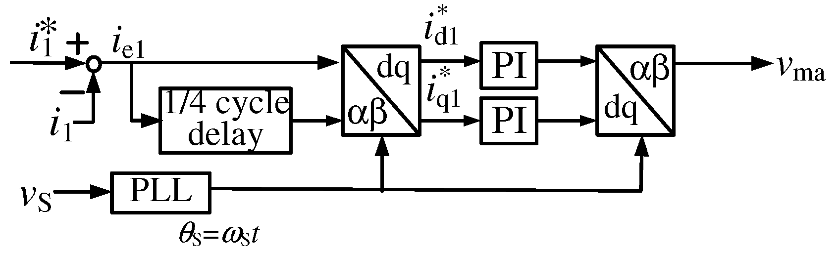
Figure 5 shows a block diagram of single-phase current feedback control in
d-
q coordinates, which was used in
Figure 2. For
in
Figure 5, the reference value
is transformed into
d-
q coordinates with the
/4 delay block, which generates the
-phase component for
. The detected output current
of the first leg of the three-leg PWM rectifier is also transformed into
d-
q coordinates with the
/4 delay block. The differences
and
between the reference values and the detected values are calculated in
d-
q coordinates. These differences
and
in
d-
q coordinates are expressed as:
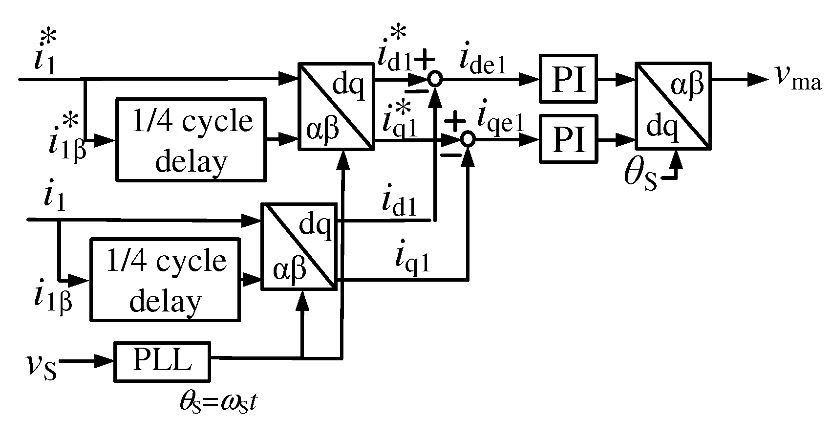
Figure 6 shows a control circuit diagram of the single-phase current feedback in
d-
q coordinates, which is used in
Figure 4. In
Figure 6, for
, the difference
between the reference value
and the detected value
is calculated, and then transformed into
d-
q coordinates with the
/4 delay block. The differences
and
are expressed as:
Equation (
12) shows that one
d-
q transformation block is enough to achieve the current controller with a PI controller in
d-
q coordinates. Thus, two
d-
q transformation blocks are removed, as shown in
Figure 4. The difference
and
are amplified by PI controllers in
d-
q coordinates. The amplified differences are retransformed into
-
coordinates, and then the triangle intersection method is used to control the output currents
and
.
Saitou and Shimizu [
25] proposed a novel current feedback control method for single-phase circuits in
d-
q coordinates, in which a Hilbert transform is used. In their method, the Hilbert transform is implemented by numerical differentiation. This may result in instability in experimental systems. Thus, for single-phase circuits, the feedback control in
d-
q coordinates with a
/4 delay block is more practicable.
3. Simulation Results
The validity and high practicability of the proposed control algorithm for the proposed smart charger are confirmed by digital computer simulation using PSIM software (ver. 10.0.6.564). The unbalanced ratio between Feeder1 and Feeder2 is defined as:
where
is the apparent power of Load1 in Feeder1, and
is the apparent power of Load2 on Feeder2.
is the total apparent power, which is the sum of the apparent powers
and
on Feeder1 and Feeder2, respectively. According to the Japanese guidelines for domestic power consumption, the unbalanced ratio should be less than 40% for domestic power consumption [
26]. Thus, Load1 of 1.2 pu is connected to Feeder1, where the power factor (PF) is 0.87, and the THD value is 23.4%. Load2 of 0.8 pu connected to Feeder2, where the PF is 0.88, and the THD value is 20.1%.
Table 1 shows the circuit constants for
Figure 4, which were used in the following simulation results.
= 0.8,
= 2.4 ms and
= 0.6 ms were used in the PID controller for CDCVC, and
= 0.04 and
= 8 ms were used in the PI controllers for current feedback control in
d-
q coordinates in
Figure 4 in the following simulation results. These values of control parameters were determined with the Ziegler–Nichols ultimate sensitivity method and then improved by digital computer simulation.
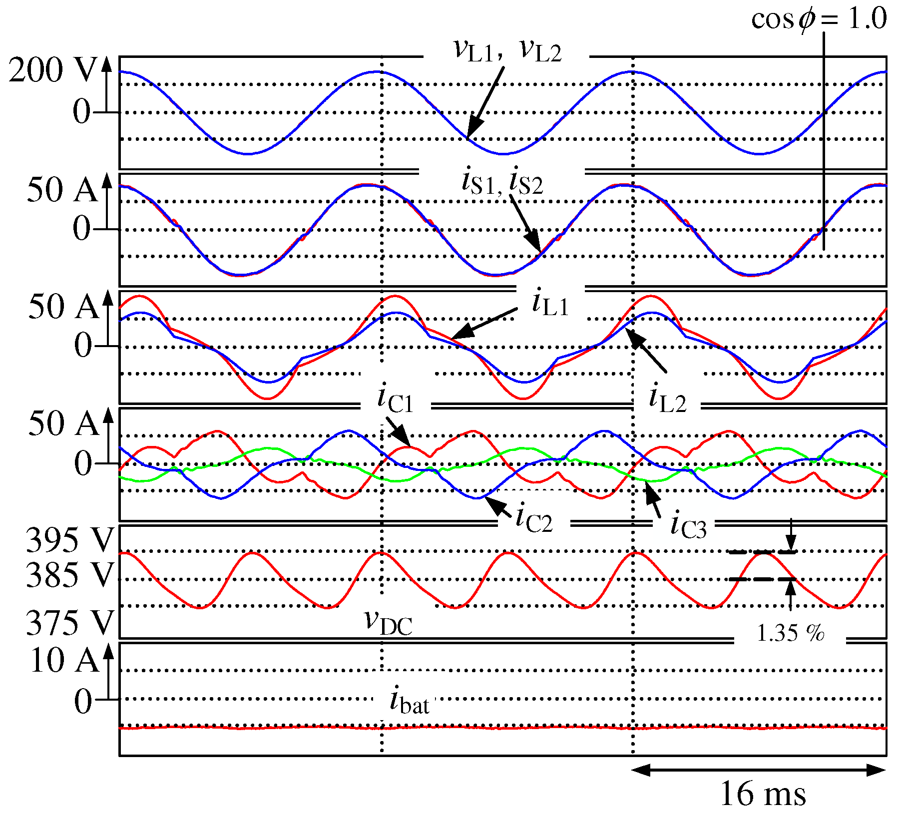
Figure 7 shows the simulation results for
Figure 4, where the proposed smart charger charges the battery with constant battery current control.
is the source voltage, and
and
are the secondary-side voltage waveforms;
and
are the secondary-side current waveforms;
and
are the load-side current waveforms of the domestic consumer;
,
, and
are the output current waveforms of the smart charger;
is the DC-capacitor voltage waveform; and
is the battery current waveform. Although the load currents
and
are unbalanced and distorted, the source currents
and
are balanced and sinusoidal with a unity power factor. The THD values of
and
are 4.2% and 3.4% respectively, under the steady state, and the voltage ripple of
is 1.35%.
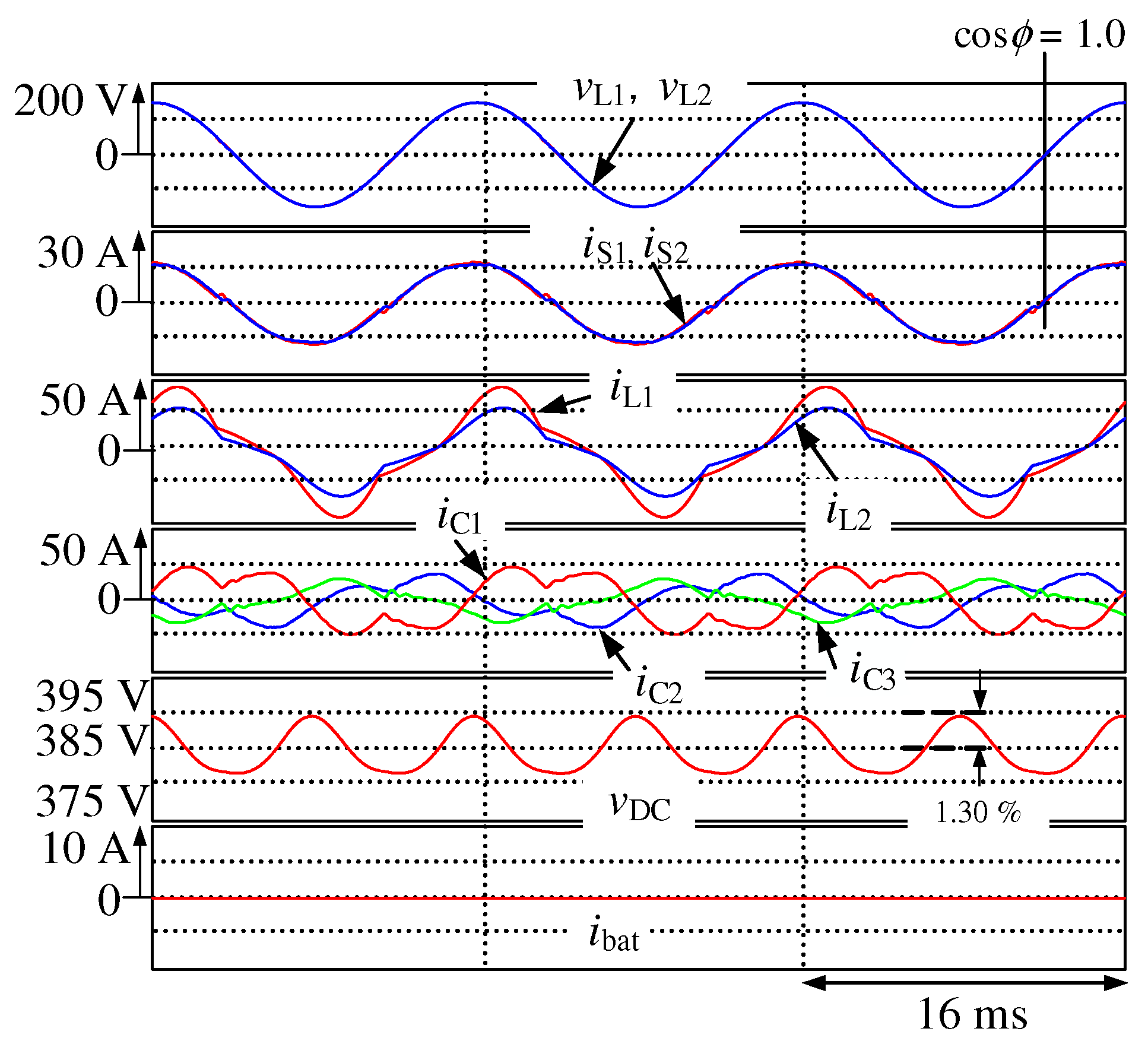
Figure 8 shows the simulation results for
Figure 4, where the proposed smart charger discharges the battery with constant battery current control. Although the load currents
and
are unbalanced and distorted, the source currents
and
are balanced with a unity power factor. The THD values of
and
are 10.8% and 7.7%, respectively, under the steady state, and the voltage ripple of
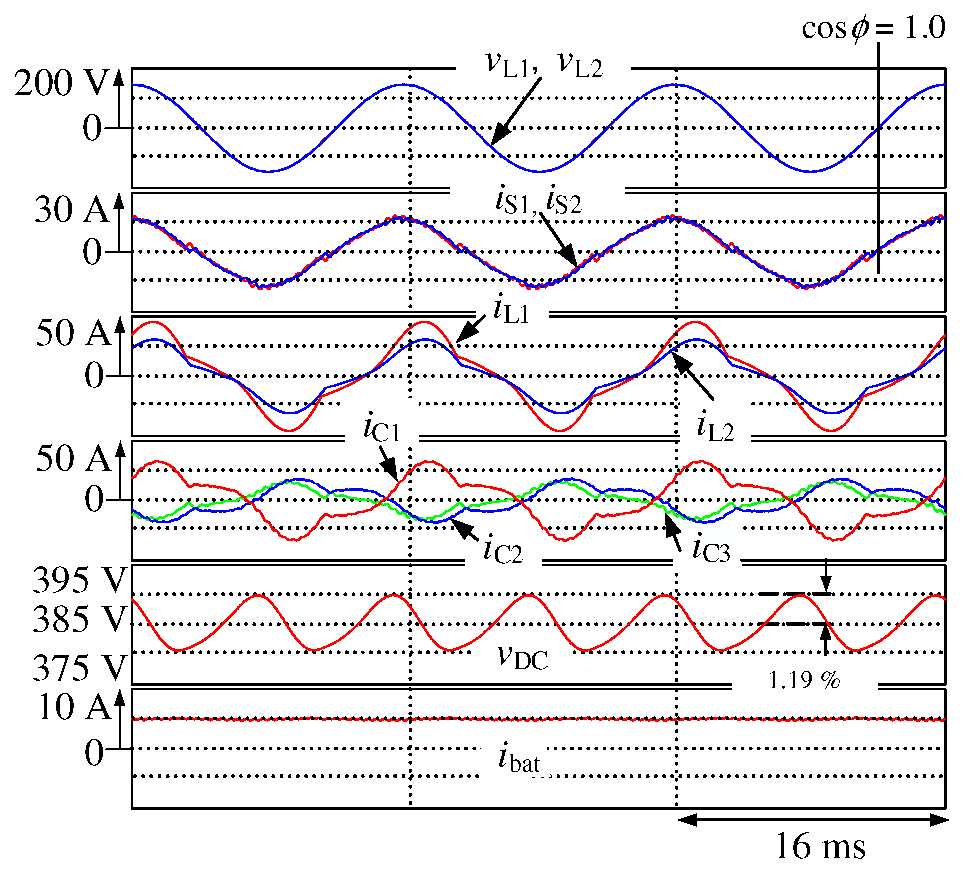
is 1.30%. Simulation results have demonstrated that sinusoidal and balanced source currents with a unity power factor are achieved on the secondary side of the PMDT during the battery-charging and -discharging operations in EVs, thereby compensating the reactive, unbalanced active, and harmonic currents. Simulation results also have demonstrated that sinusoidal and balanced source currents with a unity power factor are achieved even though EVs are not connected to the smart charger. Thus, the proposed smart charger can solve the power quality problems and reduce losses in the PMDTs.
Figure 9 shows the simulation results for
Figure 4, where an EV is not connected to the proposed smart charger. Thus, the smart charger performs as an active power-line conditioner for the domestic consumer. Although the load currents
and
are unbalanced and distorted, the source currents
and
are balanced with a unity power factor. The THD values of
and
are 4.6% and 3.8% respectively, under the steady state, and the voltage ripple of
is 1.19%.
The required capacity of the three-leg PWM rectifier, which performs as a smart charger, is now discussed. A definition of apparent power is generally used to calculate the required capacity of the PWM rectifier. The third leg of the PWM rectifier, which is connected to the neutral line, is grounded. The typically used definition of apparent power is not applicable to the three-leg PWM rectifier. In [
27], the authors have defined a current capacity
for the smart charger with a PWM rectifier in single-phase three-wire distribution feeders.
is given as:
where
is the rating of Feeder1 and Feeder2 currents. The rating of the PMDT is 6600 Vrms, 5 kVA, and 60 Hz on the primary side, and 105 Vrms on the secondary side. Thus,
is 24 Arms. From the simulation results in
Figure 7,
is 0.91 pu.
Table 2 shows relationships between the current capacity
and load conditions. The current capacity
with the larger unbalanced ratio, which is defined by Equation (
14), is larger with the larger load conditions. As mentioned above, the maximum-acceptable unbalanced ratio is 40% according to Japanese guidelines for domestic power use [
26]. Thus, the current capacity
of 0.91, which is calculated from the simulation results of
Figure 7, gives the maximum current capacity of the three-leg PWM rectifier, which performs as a smart charger. The THD values of the source currents
and
, in
Figure 7,
Figure 8 and
Figure 9, satisfy the regulations [
12]. Experimental verifications for
Figure 4 are an important issue. Thus, experimental results will be reported in another article.


