
Natural Gas Hydrate as a Storage Mechanism for Safe, Sustainable and Economical Production from Offshore Petroleum Reserves

1
Century Fathom, Los Angeles, CA 90089, USA
2
Department of Astronautical Engineering, University of Southern California, Los Angeles, CA 90089, USA
3
School of Mechanical and Aerospace Engineering, Cornell University, Ithaca, NY 14853, USA
*
Author to whom correspondence should be addressed.
Energies 2017, 10(6), 828; https://doi.org/10.3390/en10060828
Submission received: 16 April 2017
/
Revised: 6 June 2017
/
Accepted: 11 June 2017
/
Published: 20 June 2017
(This article belongs to the Special Issue Methane Hydrate Research and Development)
Abstract
:Century Fathom presents an innovative process to utilize clathrate hydrates for the production, storage and transportation of natural gas from off-shore energy reserves in deep ocean environments. The production scheme was developed by considering the preferred state of natural gas in the deep ocean and addressing the hazards associated with conventional techniques to transport natural gas. It also is designed to mitigate the significant shipping cost inherent with all methods. The resulting proposed scheme restrains transport in the hydrate form to the ocean and does not attempt to supply energy to the residential consumer. Instead; the target recipients are industrial operations. The resulting operational concept is intrinsically safer by design; environmentally sustainable and significantly cost-effective compared with currently proposed schemes for the use of natural gas hydrates and has the potential to be the optimal solution for new production of reserves; depending on the distance to shore and capacity of the petroleum reserve. A potential additional benefit is the byproduct of desalinated water.
1. Introduction
The presence of natural gas, inherent in all petroleum reserves, adds technical challenges for the production of such reserves. Frequently, the value of the gas can be less than its production cost. Historically, many operators flare this gas, or when required by regulation or statue, return the natural gas to the ground.
There are just a few conventional methods to store and transport natural gas, which is consequently referred to as stranded gas. The most efficient method is through natural gas pipelines, however production is generally limited to the location of existing infrastructure. The capital expenditure for installing new pipelines is large and is only justified for large capacity. Another potential technique is compressed natural gas (CNG), which is only viable for limited capacity.
In recent years, liquefied natural gas (LNG) [1] has become the preferred method to transport natural gas for large distances, particularly over the ocean. The necessary infrastructure has grown with facilities being created to produce, store, and transport LNG across the globe. The industry has addressed the growing production of stranded gas but also taken advantage of regional differences in the energy market. Despite the proliferation of LNG infrastructure, there remains large capital and operating expenses that can only be partially alleviated by the economy of scale.
1.1. Safety Concerns
There are numerous safety hazards inherent in the operations of LNG. There are safety concerns with simply handling and maintaining a fuel at near cryogenic temperatures (<131 °C). Throughout the lifecycle, there is nonetheless boil-off of natural gas. This by-product must be collected and either consumed locally (as a fuel) or re-liquefied. The sloshing motion of fluids in large vessels can create additional hazards; the disturbance force can be especially significant in partially-filled vessels. Another design constraint with current LNG operations is the necessity to maintain a baseline liquid level (on the order of 10% of capacity) in order to maintain the temperature in the vessel, so as to avoid repeating the initial cooling cycle. While retaining the baseline quantity does not create additional hazards, it does extend the time during which potentially hazardous conditions exist, such as when these specialty-developed ships are on a return trip, and are not providing delivery of LNG. The industry has developed mitigations to reduce the risks associated with these hazards. However there are costs associated with implementing these controls and there remains residual risk.
1.2. German SUGAR Project
The Subterranean Gas Reserves (SUGAR) [2] project funded by the German government, performed an economic analysis comparing various production, storage, and transportation mechanisms for stranded gas. The economic summary presented the optimal production scheme (pipeline, CNG, LNG, and Natural Gas Hydrate or NGH) as a function of the reservoir characteristics. The results were presented as a phase diagram of capacity vs. transportation distance with regions identifying the most cost-effective technique for the specific scenarios considered. Close to shore, pipeline was always the preferred technique while at large distances from shore, LNG was the most competitive solution. For small capacity production, there was an intermediate region for which CNG was the competitive approach. Within the considered scenarios, there was no region for which NGH represented the optimal solution.
The NGH production scheme evaluated by the SUGAR project was based upon conventional technologies. Through their scheme, natural gas was brought to the surface and then reacted under high pressure and low temperature to form hydrate pellets. The use necessitated a high pressure reactor resulting in significant capital and operating expenditures. This scheme incorporated active thermal control of the containers, adding complexity and cost to the processing and transportation systems. The project assumed transport only to the coast for regasification in the harbor terminal. The selected design architecture was one that permitted NGH pellets to be transported by ship, road, and rail. The resulting scheme incorporated robust shipping methods at an undue cost to the resulting system.
1.3. Japanese Demonstration Experiment
A Japanese consortium led by Mitsui Shipbuilding Co. has demonstrated the capability to commercialize natural gas distribution via a supply chain incorporating NGH [3]. The supply chain was optimized for the consumer, residential, and light industrial end-users. The initial goal of the demonstration project was identical to the one assessed by the German SUGAR project; it was later expanded to include overland transport. The resulting system provided energy to customers that were not connected to an energy (electricity) grid. The consumer who received NGH pellets also had a system to convert the pellets to heat and electricity for their individual needs. In the original incarnation, the initial design was based on a bulk freighter. When the concept was expanded for overland transport, it became necessary to store and transport hydrate pellets in containers which could be transported by ship and truck/rail while providing active thermal control as to prevent coalescence of NGH pellets.
The scheme validated by the Japanese was essentially the same as the scheme the German SUGAR team analyzed in their economic analysis. It should be noted that while this successful Japanese project demonstrated the engineering feasibility of production and transportation of NGH, economically it was only claimed to work for ships. The project will be discontinued.
1.4. Scientific Investigations
A number of research initiatives have explored experimentally and theoretically the formation of hydrates from methane and other gases. Researchers have been concerned with flow assurance in oil and gas pipelines, production of naturally-occurring hydrates below the ocean surface, and climate concerns [4]. Special attention has focused on the role of inhibitors to prevent the formation of hydrates [5] and surfactants which can serve to promote their formation [6,7,8]. Investigators have assessed the formation of hydrates formation in controlled environments and considered composition of gasses consistent with those in subterranean petroleum reserves [9].
2. Process Constraints Discussion
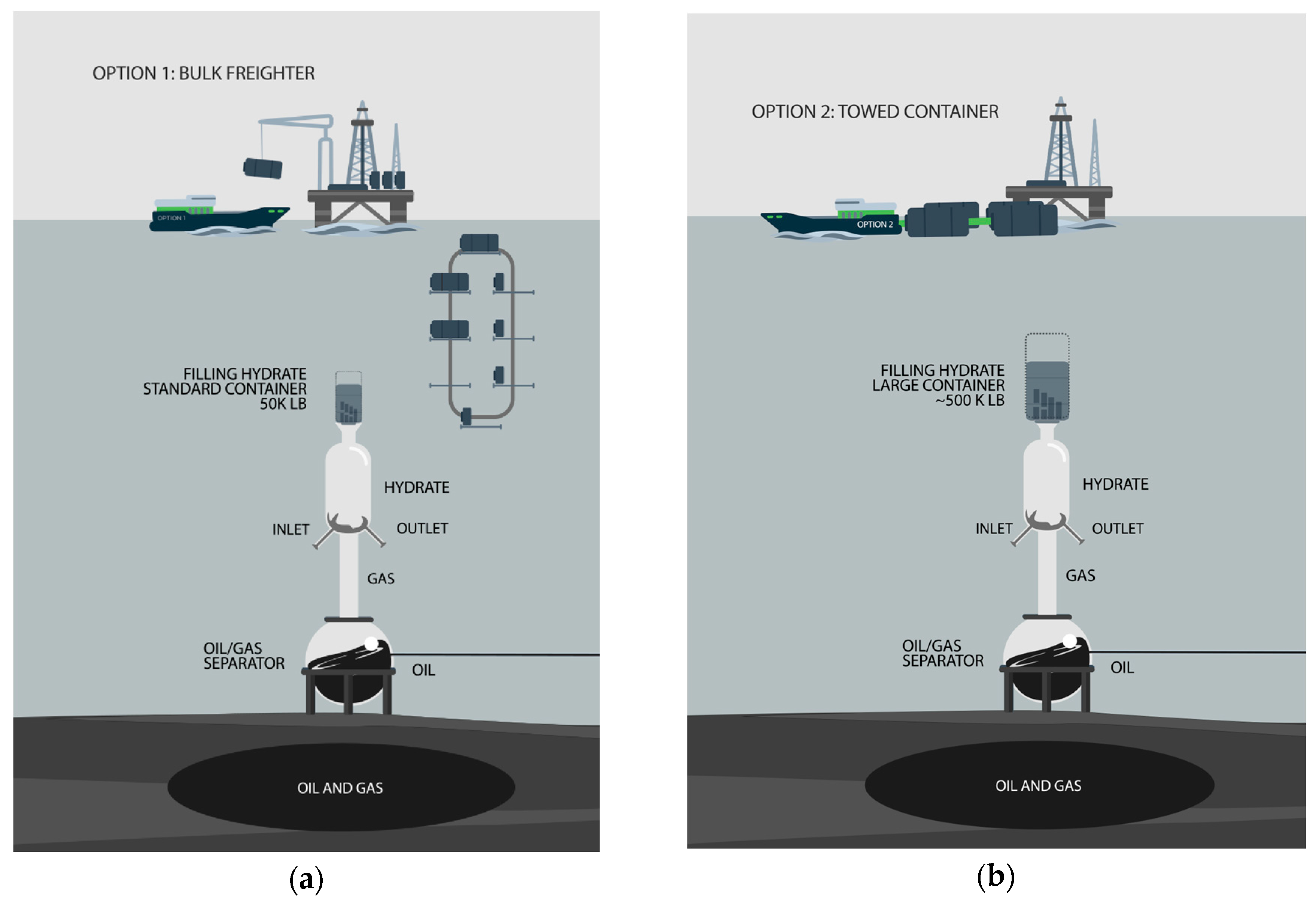
A scheme incorporating Natural Gas Hydrates has the potential to be an economically preferred solution for the production, storage, and transportation of natural gas from deep water reserves to the shore. A schematic representing the notional concept for the operation is shown in Figure 1. Two key aspects, discussed below, are necessary for the design to be economically viable. The resulting process must be developed around the design constraints.
2.1. Formation of Hydrate in the Deep Ocean
The optimal configuration takes advantage of conditions for which NGH forms in situ. The proposed method generates NGH in a region in the ocean in which the combination of pressure and temperature inherently favors their formation, by kinetics and thermodynamics. If the conversion occurs at sufficient depth, then no special machinery is needed to artificially create a lower temperature or higher pressure in order to enable conversion to occur.
2.2. Shipping Methods
A critical cost with any production scheme is the transportation expense. If standard sized cargo containers were utilized then these containers, which would be filled at the production site, could be transported using standard ships, trucks, and rail cars. This production scheme would fully utilize the existing transportation supply chain and offer a wide choice for re-gasification options including direct to consumer delivery. Unfortunately, as shown by the SUGAR team, such transportation mechanism makes the entire approach cost-prohibitive.
If NGH is transported as a large, solid physical structure then its large thermal mass and low surface area to volume ratio preclude the necessity for active thermal control. This eliminates significant expense and potential risk from the transportation process. Recognizing that a large thermal structure is required for transport on the ocean, then it should be understood that such a structure would be too heavy to be offloaded from a ship and placed onto existing trucks or rail cars. This precludes transportation to a consumer end-user, the economic unsuitability of such options was demonstrated by the Japanese experiment.
Instead, two potential options are identified; the integration of these options into the production of NGH is shown notionally in Figure 1. Option 1 incorporates the filling of standard containers (~25,000 kg) which are raised (or floated up) from the ocean floor and emptied onto a modified bulk freighter. A standard container would need to be retro-fitted with insulation to accommodate the cargo at low temperatures. It may be necessary to add a covering to provide an air-tight seal in order to capture any liberated gases. This bulk freighter would be loaded to capacity from multiple standard containers. The resulting blocks of NGH would most likely fuse together to form a single structure. When the loaded bulk freighter reaches the re-gasification facility at the shore, the NGH is be re-gasified directly from the ship.
The customizations to a standard vessel are such that they may not require the vessel to be dedicated strictly for the purpose of transport of NGH. For long haul transport, there may be an opportunity to provide return cargo transport during the return voyage in order to reduce expenses. By contrast, LNG carriers are specialty designed and must return empty (save for the 10% of capacity necessary to prevent the repeat of the initial cool-down process).
Option 2 would incorporate the filling of large hydrate containers (~500,000 kg) which are raised (or floated up) from the ocean floor to the surface and then towed to the re-gasification facility. It is envisioned that several of these containers might be tethered together in a structural frame, possibly with minimal insulation added, and then towed with a tug-boat like vessel. The tethered structure would be designed to capture any escaping natural gas.
With Option 2, the complexities of transfer of gases between vessels on the open ocean are completely eliminated. When such transfers are mandated they are designed to accommodate relative motion of up to 5 m or more in vertical height in order to account for ocean tides and weather conditions. With this option, these complexities and the associated emergency procedures and necessary operator training are eliminated. From a safety analysis perspective, these hazards are eliminated by design.
Alternately, there are shipping vessels which can be submerged. In this case, the large containers would be loaded onto existing ocean vessels which kneel into the ocean in order to slide their cargo (exceeding crane capabilities) and transported long distances.
2.3. Re-Gasification of Natural Gas
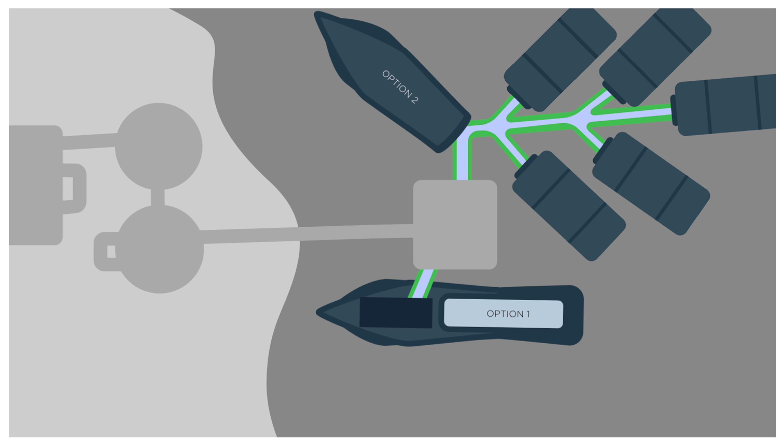
Because the structure cannot be removed from the ship, re-gasification must take place while the NGH is on the ship, i.e., in the water. Industrial facilities such as manufacturing plants or energy production plants at the shore would be natural candidates to implement such a re-gasification facility. This was the original regasification idea of the Japanese project. A notional schematic of the re-gasification facility is shown in Figure 2.
An added benefit is that these facilities often have excess heat that otherwise would be vented to the environment. Such excess heat could be harnessed for re-gasification by melting the NGH.
2.4. Additional Benefits of NGH
One potential byproduct of the hydrate process is desalinated industrial water which originates from the process at the ocean floor. Salt does not participate in the formation reaction and, provided there is a process to remove the salt, the resulting NGH can be comprised with clean water.
When producing NGH from ocean water, there will inevitably some capture of salt water in the process and between adjoining NGH crystals. The recovered water from the gasification process will be of significantly reduced salinity than the original source. The degree of desalination will depend on several factors such as the relative amount of excess ocean water used to flush heat and salt.
The partially desalinated water may be suitable for post processing desalination or may be appropriate for certain industrial uses.
3. Discussion
There are four technical outstanding issues with the development of this production scheme. First, it is necessary to produce the NGH from methane at the ocean floor. Second, the method relies on the ‘self-preservation effect’ of the NGH. Third, a special container and processing system must be developed in order to enable the production at the bottom of the ocean and transport to the surface and then to shore. Finally, the re-gasification process must be developed. The engineering analysis and industry efforts in this field provide high confidence that the engineering challenges associated with all of these issues will be solved.
3.1. Formation of NGH—In Situ Conditions
The oil industry has been exploring in the ocean at far greater depths than the minimum depth required for this scheme. At these depths, natural gas hydrates form naturally if sufficiently high flux of natural gas is present [10]. The natural phenomenon of hydrate formation has been directly observed in blowouts of oil production rigs in the deep ocean. Comparing the kinetics of hydrate formation and the thermoclines in the deep ocean around the world, it can be shown that hydrates of natural gas mixtures can form naturally in depths starting at 200 m.
The naturally occurring phenomenon of hydrate formation in marine sediments in the deep ocean is well known. Recent estimates constrained by direct sampling suggest the global inventory occupies between 1 × 10¹⁵ and 5 × 10¹⁵ m3 (0.24 to 1.2 million cubic miles) [11]. There exist hydrates in many regions of the world where there are no domestic oil reserves [12,13]. Additional evidence for the formation of hydrates are the difficulties in stopping the oil leak which developed following the blowout at the Deepwater Horizon oil rig [14,15]. The critical issue is whether the reaction can be controlled in such a manner to produce NGH at manageable rates for efficient capture.
3.2. Self-Preservation Effect
Self-preservation [16] is a phenomenon observed below the meting point of ice in which clathrate hydrates dissociate at rates several orders of magnitude slower than would normally be expected given known equilibrium profiles of temperature and pressure of formation. The phenomenon permits gas storage with low boil-off rates at pressure and temperature conditions that would be anticipated during shipping.
The proposed scheme takes advantage of this self-preservation phenomenon, which is compounded with large structures (~500,000 kg) given the small surface area. Long-distance transport can be achieved without active temperature control. The resulting transportation is simple, and minimal insulation is needed to maintain the temperatures below the melting point of ice provided a large thermal mass of hydrate is produced. Even with large structures, there will be some escaping natural gas resulting from decomposition or diffusion. With Option 1, it may be necessary and advantageous to cover the NGH on the bulk freighter so as to collect this product. With Option 2, it is anticipated that the towed structure will include an internal method collection of the liberated natural gas. It is anticipated that the total quantity of gas will be relatively small so that it can be compressed and stored conveniently.
Given the large structures that are fabricated for transportation, it is recognized that it will not be possible to lift them out of the water or transport them by truck or rail. As such, re-gasification must occur at the port or in the water near shore (<2 km). Such infrastructure could be integrated with industrial applications.
3.3. Containers for Natural Gas Hydrate
In order to realize this production scheme, it is necessary to utilize a container that can function in the deep ocean. This container must integrate with the production, storage, and processing system, throughout the lifecycle, i.e., at the deep ocean, on the ocean surface, and at the re-gasification facility. This container must be flexible so that it increases its interior volume as it is being filled. Because the container will increase in volume as it is filled, it will not need to sustain the external load associated with the ocean depth. That is, the container will act more as a large balloon than as a rigid shell as pressure equilibrium between the outside and inside will be naturally maintained. The containers will, however, need to maintain some structural integrity throughout the filling process and be capable of sustaining a limited pressure differential of one or two atmospheres when a small amount hydrate dissociates into gas and ice near the ocean surface, whereupon the released gas is siphoned off, thus preventing a pressure buildup.
To achieve such properties of the container, it will need to have at least three additional critical properties. First, it must be fabricated with a material with a high strength to weigh ratio (at least an order magnitude greater than conventional metals). Second the resulting container must be resilient to corrosion in the marine environment. Third, the container must have an approximate matched density to water, resulting in neutral buoyancy for the fabricated vessel, which is essential for maneuverability. The investigators’ experience in space exploration industry will enable the design and fabrication of these containers. It should be noted that the requirements for the vessel in which the hydrates are formed are distinct from the requirements for the vessel in which NGH is stored and transported.
3.4. Re-Gasification
A facility is proposed that would utilize excess heat from industrial facilities at the shore to convert NGH to desalinated water and natural gas. Impurities that are inherent in off-shore reservoirs would need to be separated from the recovered natural gas. These might include sulfur and trace amounts of mercury. The industrial facility would be the natural consumer of the produced natural gas. The facility might also be the consumer for the water by-product. As discussed earlier, additional processing may be necessary to remove remaining salt from the water. Per US regulations, such water would not be potable. However, additional testing and changes in regulations may make this water available for potential uses.
4. Conclusions
With this proposed scheme, natural gas hydrates are presented as a potentially economically-preferred storage and transportation solutions for the production of stranded natural gas from offshore reserves. An international Patent Cooperation Treaty application [17] on this proposed method was filed on October 2016. In the International Search Report and Written Opinion issued in January 2017, the United States Patent and Trademark Office, in preliminary examination, found all the patent application claims to be novel and useful.
Author Contributions
Motivated by extensive study of commissioned reports on the circumstances of Deepwater Horizon blowout, S. Leigh Phoenix conceived the overall conceptual model of NGH processing in the deep ocean environment, and performed the initial engineering calculations on its feasibility. Study of NGH packaging, shipping, reconversion to natural gas, and the contextual economics was largely done by Michael T. Kezirian Development of most other technical aspects, including writing a patent, was a joint effort of the authors. Michael T. Kezirian proposed and largely wrote the paper.
Conflicts of Interest
The authors declare no conflict of interest.
References
- Tusiani, M.D.; Shearer, G. LNG: Fuel for a Changing World—A Nontechnical Guide, 2nd ed.; PennWell: Tulsa, OK, USA, 2016. [Google Scholar]
- Rehder, G.; Eckl, R.; Elfgen, M.; Falenty, A.; Hamann, R.; Kähler, N.; Kuhs, W.F.; Osterkamp, H.; Windmeier, C. Methane Hydrate Pellet Transport Using the Self-Preservation Effect: A Techno-Economic Analysis. Energies 2012, 5, 2499–2523. [Google Scholar] [CrossRef]
- Satoo, N. Development of Natural Gas Hydrate (NGH) Supply Chain. In Proceedings of the 25th World Gas Conference, Kuala Lumpur, Malaysia, 4–8 June 2012. [Google Scholar]
- Sloan, E.D.; Koh, C. Clathrate Hydrates of Natural Gases, 3rd ed.; CRC Press: Boca Raton, FL, USA, 2008. [Google Scholar]
- Seo, Y.; Kang, S.P. Inhibition of Methane Hydrate Re-formation in Offshore Pipelines with a Kinetic Hydrate Inhibitor. J. Pet. Sci. Eng. 2012, 88–89, 61–66. [Google Scholar] [CrossRef]
- Brinchi, L.; Castellani, B.; Rossi, F.; Cotana, F.; Morini, E.; Nicolini, A.; Filipponi, M. Experimental Investigations on Scaled-up Methane Hydrate Production with Surfactant Promotion: Energy Considerations. J. Pet. Sci. Eng. 2014, 120, 187–193. [Google Scholar] [CrossRef]
- Ando, N.; Kuwabara, Y.; Mori, Y.H. Surfactant effects on hydrate formation in an unstirred gas/liquid system: An experimental study using methane and micelle-forming surfactants. Chem. Eng. Sci. 2012, 73, 79–85. [Google Scholar] [CrossRef]
- Lee, S.Y.; Kim, H.C.; Lee, J.D. Morphology study of methane–propane clathrate hydrates on the bubble surface in the presence of SDS or PVCap. J. Cryst. Growth 2014, 402, 249–259. [Google Scholar] [CrossRef]
- Mori, Y.H. On the Scale-up of Gas-Hydrate-Forming Reactors: The Case of Gas-Dispersion-Type Reactors. Energies 2015, 8, 1317–1335. [Google Scholar] [CrossRef]
- Yapa, P.R.; Chen, F. Behavior of Oil and Gas from Deepwater Blowouts. J. Hydraul. Eng. 2004, 130, 540–553. [Google Scholar] [CrossRef]
- Milkov, A.V. Global estimates of hydrate-bound gas in marine sediments: How much is really out there? Earth Sci. Rev. 2004, 66, 183–197. [Google Scholar] [CrossRef]
- Kvenvolden, K.A.; Ginsburg, G.D.; Soloviev, V.A. Worldwide distribution of subaquatic gas hydrates. Geo-Marine Lett. 1993, 13, 32–40. [Google Scholar] [CrossRef]
- Max, M.D.; Johnson, A.H.; Dillon, W.P. Economic Geology of Natural Gas Hydrate; Springer Science & Business Media: Dordrecht, The Netherlands, 2005; Volume 9. [Google Scholar]
- Bolstad, E.; Clark, L.; Chang, D. Engineers Work to Place Siphon Tube at Oil Spill Site. Available online: http://www.icyte.com/system/snapshots/fs1/7/f/0/c/7f0c761399d7de5ece45aa69ca918ad5f8a1b880/index.html (accessed on 15 May 2010).
- Daniel, C. Giant Dome Fails to Fix Deepwater Horizon Oil Disaster. Available online: http://blogs.nature.com/news/thegreatbeyond/2010/05/_giant_dome_fails_to_fix_deepw.html (accessed on 10 May 2010).
- Stern, L.A.; Circone, S.; Kirby, S.H.; Durham, W.B. Anomalous preservation of pure methane hydrate at 1 atm. J. Phys. B Chem. 2001, 105, 1756–1762. [Google Scholar] [CrossRef]
- Phoenix, S.L.; Kezirian, M.T. Method and System for Extracting Stranded Gas from Underwater Environments, Converting It to Clathrates, and Safely Transporting It for Consumption. International Patent Application No. PCT/US2016/055912, 7 October 2016. [Google Scholar]
Figure 1.
Notional concept of the proposed method for extracting natural gas from off-shore petroleum reserves. (a) Option 1, natural gas hydrate is transported in a bulk freighter. Standard-sized containers are filled near the ocean floor, raised (or floated up) to the surface, and emptied onto the bulk freighter which is then covered before transport to shore; (b) Option 2, natural gas hydrate is transported by towed containers. Large containers are filled near the ocean floor, raised (or floated up) to the surface, and transported to shore.

Figure 2.
Notional concept of the proposed method for re-gasifying natural gas from natural gas hydrates produced from off-shore petroleum reserves. The facility would accommodate the appropriate shipping option.
Figure 2.
Notional concept of the proposed method for re-gasifying natural gas from natural gas hydrates produced from off-shore petroleum reserves. The facility would accommodate the appropriate shipping option.
© 2017 by the authors. Licensee MDPI, Basel, Switzerland. This article is an open access article distributed under the terms and conditions of the Creative Commons Attribution (CC BY) license (http://creativecommons.org/licenses/by/4.0/).
Share and Cite
MDPI and ACS Style
Kezirian, M.T.; Phoenix, S.L. Natural Gas Hydrate as a Storage Mechanism for Safe, Sustainable and Economical Production from Offshore Petroleum Reserves. Energies 2017, 10, 828. https://doi.org/10.3390/en10060828
AMA Style
Kezirian MT, Phoenix SL. Natural Gas Hydrate as a Storage Mechanism for Safe, Sustainable and Economical Production from Offshore Petroleum Reserves. Energies. 2017; 10(6):828. https://doi.org/10.3390/en10060828
Chicago/Turabian StyleKezirian, Michael T., and S. Leigh Phoenix. 2017. "Natural Gas Hydrate as a Storage Mechanism for Safe, Sustainable and Economical Production from Offshore Petroleum Reserves" Energies 10, no. 6: 828. https://doi.org/10.3390/en10060828
Note that from the first issue of 2016, this journal uses article numbers instead of page numbers. See further details here.