Research on Capacitance Current Compensation Scheme of Current Differential Protection of Complex Four-Circuit Transmission Lines on the Same Tower


1
State Key Laboratory of Advanced Electromagnetic Engineering and Technology, Huazhong University of Science and Technology, Wuhan 430074, China
2
Electric Power Security and High Efficiency Laboratory, Huazhong University of Science and Technology, Wuhan 430074, China
*
Author to whom correspondence should be addressed.
Energies 2017, 10(7), 1071; https://doi.org/10.3390/en10071071
Submission received: 19 June 2017
/
Revised: 10 July 2017
/
Accepted: 19 July 2017
/
Published: 23 July 2017
(This article belongs to the Section F: Electrical Engineering)
Abstract
:Current differential protection is the main protection of transmission lines which include multi-circuit lines on the same tower, and whose sensitivity and reliability of differential protection is mainly affected by the distributed capacitive current. For the four-circuit line on the same tower, due to the influence of coupling between the loop road, the distributed capacitance current increases significantly when compared with ordinary lines, affecting the sensitivity of the current differential protection, especially for different voltage levels throughout the four-circuit lines on the same tower. The relationship of the electrostatic coupling between the circuits is more complex, and increases the difficulty of the compensating the distributed capacitance current. This paper is based on the electrostatic coupling principle of four-circuit lines on the same tower, establishes the distributed parameter model of four-circuit transmission lines on the same tower, and discusses the effect of circuit operation mode on the compensation of capacitance current differential protection when different faults occur on the complex four-circuit transmission lines on the same tower. A new compensation scheme suitable for capacitive current compensation is proposed. Simulation results show that this capacitive current compensation scheme can effectively improve the performance of current differential protection.
1. Introduction
With the fast development of the domestic economy and power load growth, the need to improve the transmission capacity of the power grid has become more urgent. In recent years, due to its advantage in large transmission capacity and savings in the transmission corridor, parallel transmission lines on the same tower have been widely adopted in the domestic power grid. With the advance in design and manufacturing technology, and to meet the needs of the different transmission corridor, except the double-circuit lines on the same tower, in engineering applications have been derived from many other complex tower structures, such as different voltage multi-circuit lines on the same tower [1,2,3,4]. In particular, the four-circuit lines on the same tower have been applied gradually as a representative of multiple circuits on the same tower. For multi-circuit lines on the same tower, due to the close spacing of the wires, there is a complex electromagnetic and electrostatic coupling relationship between the wires, the operation of the system and the action of protection needing higher requirements. For lines on the same tower, the protection needs to have the ability of selecting the faulty phase, so the current differential protection has been widely used in the multi-circuit lines on the same tower as it has a natural ability to choose the faulty phase.
The main factor that affects the reliability and sensitivity of current differential protection is the presence of distributed capacitance current which is closely related with the length of lines, tower structure and operation mode, so how to reasonably compensate the capacitance current is an important issue to be solved in the practical applications of current differential protection [5,6,7,8,9,10].
Many studies [11,12,13,14,15,16,17] have analyzed the influence of capacitive current on the line current differential protection, and proposed a corresponding compensation scheme. However, these are mainly aimed at whole transmission lines, but in the actual project the segment multi-circuit lines on the same tower exist, and the relationship of electrostatic coupling between the wires is more complicated. This occurs because the phase conductors of each line are close, so capacitive parameters vary when line operation mode is changed, therefore effective measures need to be taken to reduce any adverse effects of the capacitance current which due to changes in operating mode for the current differential protection in a complex line on the same tower.
In this paper, the effects of different operation modes (OM) on the capacitance current compensation of current differential protection of four-circuit transmission lines on the same tower were analyzed, through theoretical analysis and simulation calculations. The capacitor compensation scheme was proposed for the segregated phase current differential protection and the zero-sequence current differential protection which are suitable for the complex four-circuit lines on the same tower under different operating conditions. Based on the PSCAD/EMTDC (Manitoba HVDC research centre, Winnipeg, MB, Canada) and MATLAB (MathWorks, Natick, MA, USA) simulation software, the model of four-circuit lines on the same tower was established, and the effectiveness of the proposed method was verified.
2. The Distributed Capacitance Current Compensation Method of Current Differential Protection
2.1. Influence of Capacitive Current on the Current Differential Protection
The inter phase capacitive current and the capacitive current between parallel lines outflow from the lines, which form part of the tripping current of differential protection. Under normal operation or external fault conditions, the distributed capacitive current will reduce the security of the current differential protection, and even cause malfunction. In particular, for long parallel extremely high voltage/ultra-high voltage EHV/UHV transmission lines, the inductive reactance of bundled conductors decreases, and the distributed capacitance increases, this leads to the effect of distributed capacitive current on current differential protection becoming more apparent. Thus, effective measures need to be taken to reduce the adverse effects of the capacitive current.
The principle of current differential protection is based on Kirchhoff's current law, which has good selectivity, and is the chosen main protection of transmission lines. Figure 1 shows the influence of capacitance current on current differential protection.
In Figure 1, and are the measured current of the two ends of the transmission lines, which contains the distributed capacitive current; and and are equivalent to the distributed capacitive current.
When a short circuit fault occurs inside the protected line (d1), the fault current flowing through the M and N is in a positive direction, , and is the short-circuit current of the fault point. When a short-circuit fault occurs outside the protected line (d2), or the line is in the normal operation, as per the provisions of the current positive direction, the current direction of is positive, the current direction of is negative, the current of the two sides are equal, but opposite, namely .
Thus it can be seen that there is a big difference when the protected elements occurs in the internal faults and external faults. One is a short circuit current, another value is almost zero, and a current differential protection is formed by using this difference between the two.
The typical criterion of segregated phase current differential protection is given as follows:
Zero-sequence current differential protection equation is as follows:
where is the differential current, ; Ir is the restraint current, ; , is the current phasor at both ends of the transmission line, respectively; K1 and K2 is the restraint factor, as per the engineering application, K1 = 0.6, K2 = 0.75; is the zero-sequence differential current, is the zero-sequence restraint current; and is the setting value of segregated phase current differential protection and zero-sequence current differential protection, respectively.
When the four-circuit transmission line on the same tower is in the no-load operation condition, the load current circuit is zero, and both sides of the bus are capacitive current considering the distributed capacitance of the transmission line, Equation (2) is always established. To prevent the mis-operation caused by the distributed capacitance current, the setting value of Equation (1) to should be set in accordance with escape the maximum value of the line transient capacitance current, and the sensitivity of the protection will be affected. When the line voltage level is high and the length of the line increases, the distribution capacitance current of the transmission line increases gradually, and the transient value will be larger.
For high voltage and short distance transmission lines, the capacitance current is not large, that is, the current of the two ends of the line is not large, and the current differential protection can avoid the unbalance current by adjusting the value of the protection.
For most extra-high voltage four-circuit transmission lines on the same tower, due to the circuit adopting bundle conductors and long lines, the line inductance is reduced and the distribution capacitance increases. The distributed capacitance equivalent capacitive reactance is greatly reduce, charging capacitance current is larger as the length of the lines increases, and the line capacitance electric flow influence on current differential protection is more obvious. The sensitivity and safety of the current differential protection can be greatly reduced by raising the setting value of protection through the escape capacitive current. Therefore, effective measures should be taken to compensate for the capacitive current to reduce the negative effect of the capacitor current.
2.2. Principle Analysis of Capacitive Current Compensation of Current Differential Protection
To eliminate the effects of capacitive current, a common solution is to increase the fixed value of the starting current or to compensate the capacitive current. At present, a raising the fixed value of the starting current reduces the sensitivity of the current differential protection, the capacitive current compensation is usually adopted for long multi-circuit lines on the same tower.
2.2.1. Capacitive Current Compensation on Single Circuit
Compensation can be conducted in two ways: in half-length and full-length compensation modes. In brief, capacitive current compensation, takes a half-length compensation mode, and the equivalent circuit of transmission lines is shown in Figure 1, based on the lumped parameter Π equivalent circuit model. The calculation involves following steps [16]:
- (1)
- Select the numerical filter algorithm, the phase voltage sampling value of the line at both ends to be filtered to obtain the amplitude and phase of the fundamental wave voltage.
- (2)
- Using the symmetrical component method to get the positive, negative and zero-sequence voltage from the three-phase fundamental voltage.
- (3)
- The positive, negative and zero-sequence compensated currents of the line at both ends can be calculated by using Equation (5).where Y represents the code for the line port (M,N), , and is the voltage of the two ends of the lines.
- (4)
- The compensation capacitor current is calculated by using the inverse operation of the symmetrical component, to obtain the three phase capacitor current. If XC1 = XC2, the compensation capacitance current of the A phase in the steady state can be obtained as follows:In the same way, we can obtain the compensation capacitor current of B phase and C phase.
- (5)
- The compensated differential current and the braking current of each phase can be obtained by Kirchhoff's current law. Half-length compensated differential current terminals m and n can be obtained as follows:
2.2.2. Capacitive Current Compensation on Complex Four-Circuit Lines on the Same Tower
The close distance between the wires of the four circuit lines on the same tower means that the electrostatic coupling between the two lines is more serious, so the capacitive current compensation not only needs to consider the ground capacitance and inter phase capacitance, but also the capacitance between the lines. As ultra high voltage and extra high voltage long distance transmission line, have a large the capacitance current, study is required on the capacitance current compensation methods which are applied to the four-circuit lines on the same tower, to improve the reliability and sensitivity of the current differential protection.
At present the compensation scheme of four-circuit lines on the same tower has only been verified on the model of the whole four-circuit transmission lines on the same tower, and does not take into account the capacitance current compensation of complex four-circuit transmission lines on the same tower model where the inter phase electrostatic and electromagnetic coupling relations between the lines are more complex.
In this paper, the electrostatic coupling between phases and the lines was considered, using the corresponding distribution parameters of the equivalent circuit and lumped parameter Π model to set up the equivalent circuit model of the line.
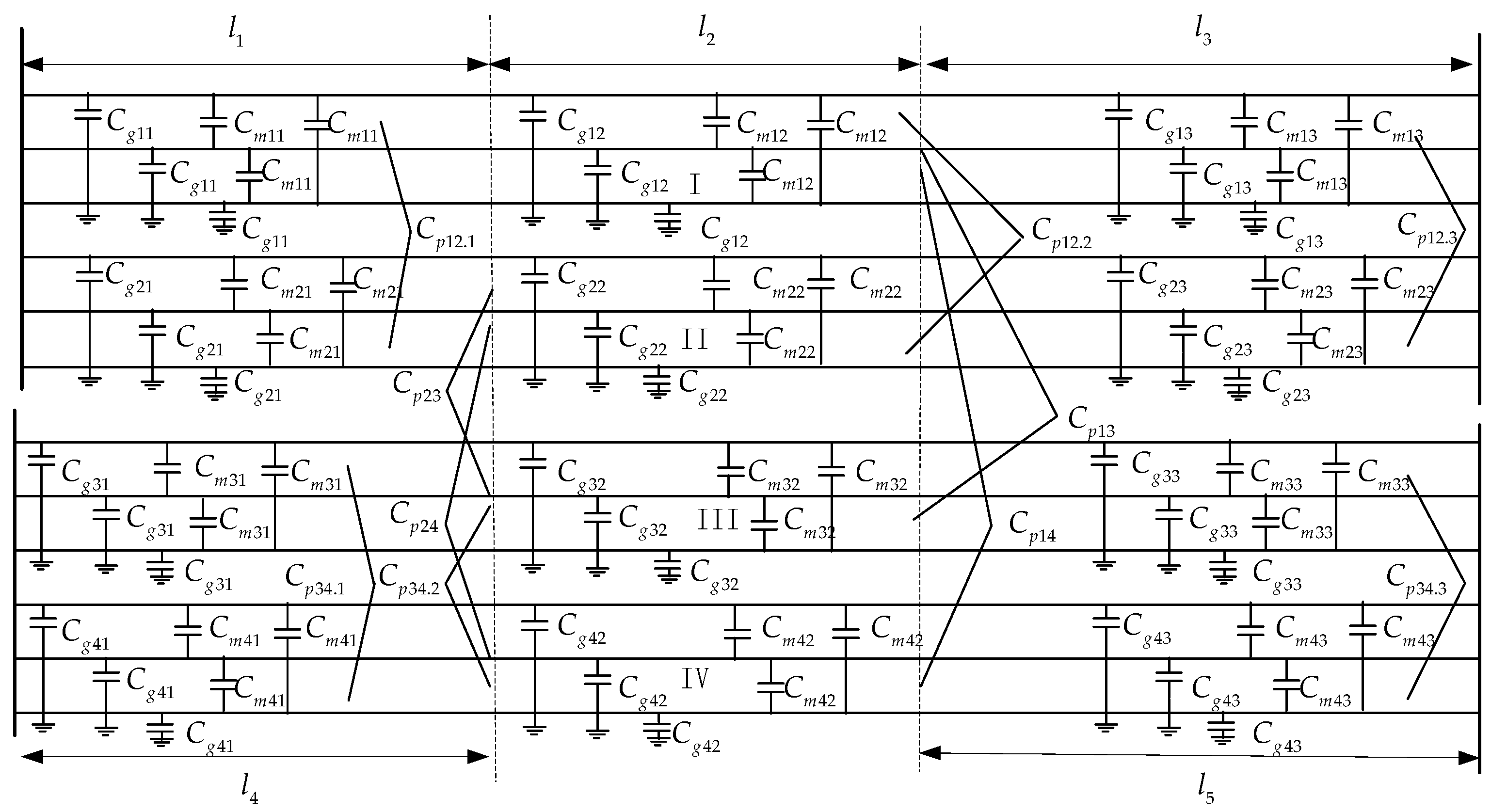
As the relationship of the electrostatic coupling between the four-circuit transmission lines on the same tower is more complicated, to simplify the analysis, it was assume that the transmission line is completely transposed. Capacitance distribution of the line model in our study is shown in Figure 2.
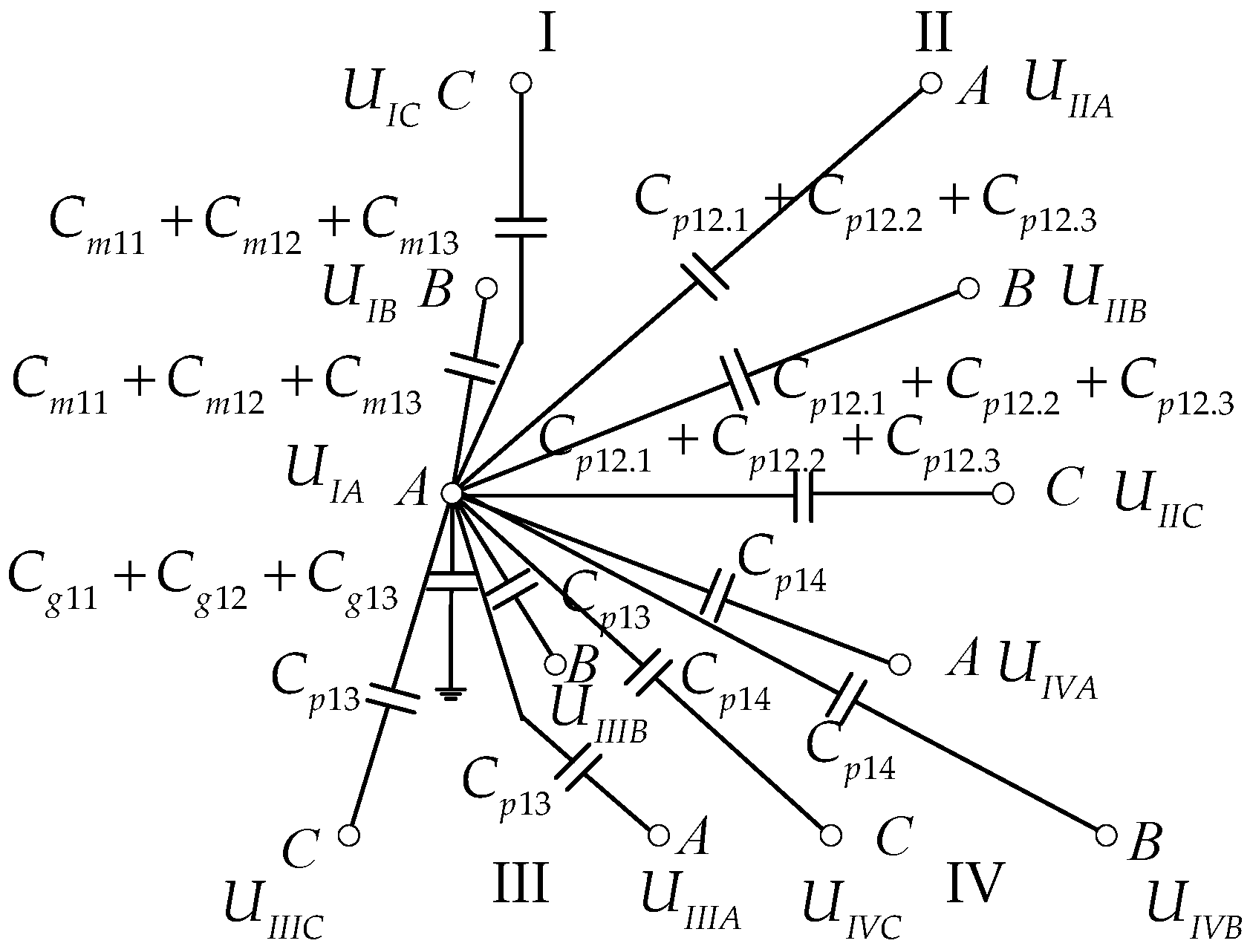
Based on the multi-conductor system theory of partial capacitance in the engineering electromagnetic field and taking phase A of the first circuit line as an example, the equivalent circuit model characterized by partial capacitance is shown in Figure 3.
The relationship of electric charge and voltage of phase A of the first circuit line can be obtained from Figure 3, which is presented by the following matrix:
In the same way, the relationship between the charge and the voltage of each wire is similar to Equation (8) where there is a similar relation expression between the charge and the voltage of each wire of the other four lines on the same tower (circuit lines II, III and IV). It can be seen in Figure 2 that the relationship between the charge and the voltage of each wire of circuit I, II, III and IV is expressed as the matrix form as follows:
where,
The relationship between the current and the voltage of the first line of complex four-circuit lines on the same tower is expressed in the form of the matrix as follows:
where:
When the four lines are in parallel operation, the bus voltage of the two lines (which are the same voltage level) is generally the same, that is , , , , , . If the half compensation method is adopted, we can obtain the expression of capacitive current as follows:
Lastly put Equations (11) and (12) into Equation (7), the compensation differential current of complex four-circuit lines on the same tower can be obtained.
To get the sequence capacitance parameter matrix of each circuit, the charge and voltage in each loop are transformed into two groups of symmetrical components where the transformation matrix is:
Then there is:
where,
From Equation (14), if the lines complete transposition, the phase line parameters are the same, the positive and negative-sequence parameters of complex four-circuit lines on the same tower are independent and the positive and negative-sequence capacitor is equal. If we take the first line as an example, , which is namely the positive and negative-sequence compensation of the capacitance current from the line change of the mode of operation, it is easy to obtain the positive and negative-sequence distribution capacitive current magnitude, that is, the positive and negative-sequence capacitance current compensation is not affected by the change of line operation mode, so it is easy to obtain the positive and negative-sequence distribution capacitance current. The zero-sequence capacitance parameters of each line is related to the zero-sequence voltage of the other three lines, that is, the zero-sequence distribution capacitance is affected by the operation mode. Therefore, it is necessary to consider the influence of different operation modes on the zero-sequence capacitance current if it needs to compensate the distribution capacitance current of the four-circuit lines.
3. Influence of Operation Modes on the Capacitive Current Compensation
3.1. Analysis of the Influence of Operation Mode on the Parameters of Distributed Capacitance
The operation mode of complex four-circuit lines on the same tower is various and coupled complex. Below are five typical examples of operation modes used to analysis the effect of operation mode of complex four-circuit lines on the same tower with distributed capacitance sequence parameters: one circuit line is in normal operation and the other three circuit lines are grounded for maintenance(M1 operation mode), two lines are in normal operation and the other two lines are grounded for maintenance (M2 operation mode), two lines are in normal operation and the other two circuits are disconnected (M3 operation mode), three lines are in normal operation and another circuit line is grounded for maintenance (M4 operation mode), and four lines in parallel operation (M5 operation mode).
- (1)
- One circuit line is in normal operation and the other three circuit lines are grounded for maintenance.
When circuit line I is running normally, the II, III and IV loops are grounded for maintenance, there are , .
Put Equation (15) into Equation (14) and the zero-sequence capacitance of circuit line I is .
- (2)
- Two lines are in normal operation and the other two lines are grounded for maintenance.
Assuming that circuit lines I and II are running normally, and circuit lines III and IV are grounded for maintenance. The potential of circuit lines III and IV is zero, that is , .
Put Equation (16) into Equation (14), and the zero-sequence capacitance of circuit line I is . The zero-sequence capacitance of t circuit line II is .
- (3)
- Two lines are in normal operation and the other two lines are disconnected.
Assuming that circuit lines I and II are running normally, and that lines III and IV are disconnected. The charge of circuit lines III and IV is zero, that is, .
Put Equation (17) into Equation (14), and the zero-sequence capacitance of circuit line I is . The zero-sequence capacitance of circuit line II is .
- (4)
- Three lines are in normal operation and another circuit line are grounded for maintenance.
Assuming that circuit lines I, II and III are in parallel operation, and circuit line IV is grounded for maintenance, the potential of circuit line IV is zero, where , and the charge of the wire is zero, that is,
Circuit lines I, II and III are in parallel operation, if two sets of double-circuit lines are the whole lines on the same tower. The zero-sequence voltage of circuit line II is considered the same as the zero-sequence voltage of circuit I when the fault occurs in circuit line I and the zero-sequence voltage of circuit transmission line III is zero. The zero-sequence capacitance of circuit line I is , the zero-sequence capacitance of circuit line II is . This is like the zero-sequence compensation under the operation mode where two circuit lines on the same tower are in normal operation, and the other two circuit lines are grounded for maintenance.
- (5)
- Four lines are in parallel operation.
If the two sets of double loop are the whole lines on the same tower, it is that the zero-sequence voltage of circuit line II is considered the same as the zero-sequence voltage of circuit line I when the fault occurs in circuit line I and the zero-sequence voltage of the double-circuit transmission lines in the other group is zero. The zero-sequence capacitance of circuit line I is , the zero-sequence capacitance of circuit line II is .
This is like the zero sequence compensation under the operation mode where two circuit lines on the same tower are in normal operation, and the other two circuit lines are grounded for maintenance.
The process of derivation and analysis under other operating conditions is shown in Appendix A.
3.2. Capacitor Current Compensation Scheme of Phase Current Differential Protection
The positive-sequence and negative-sequence current capacitance with line operation mode change had little effect, and the effect of the zero-sequence capacitance current on operation mode was larger; for phase segregated current differential protection, due to the proportion of the zero-sequence capacitance current is relatively small, and the capacitance current compensation did not consider the impact of the operating mode, regardless of the complex structure on the same tower, (such as mixed compression on the same tower, the end portion of the same tower, or intermediate on the same tower), the compensation method can be conducted based on the situation of four lines in parallel operation on the same tower.
3.3. Capacitor Current Compensation Scheme of Zero-Sequence Current Differential Protection
To solve the problem of complex four-circuit lines on the same tower, a capacitance current compensation scheme is required as per the different operation modes. Based on the above analysis, for a mixed voltage four-circuit transmission line on the same tower, an approximate assumption of the zero-sequence voltage of another voltage grade line is zero, the zero-sequence capacitance current compensation according to the operation mode of this voltage grade line is in normal operation and the other voltage grade lines are grounded for maintenance.
4. Simulation Verification of the Capacitive Current Compensation of Four-Circuit Lines on the Same Tower
4.1. Simulation Model of Four-Circuit Lines on the Same Tower
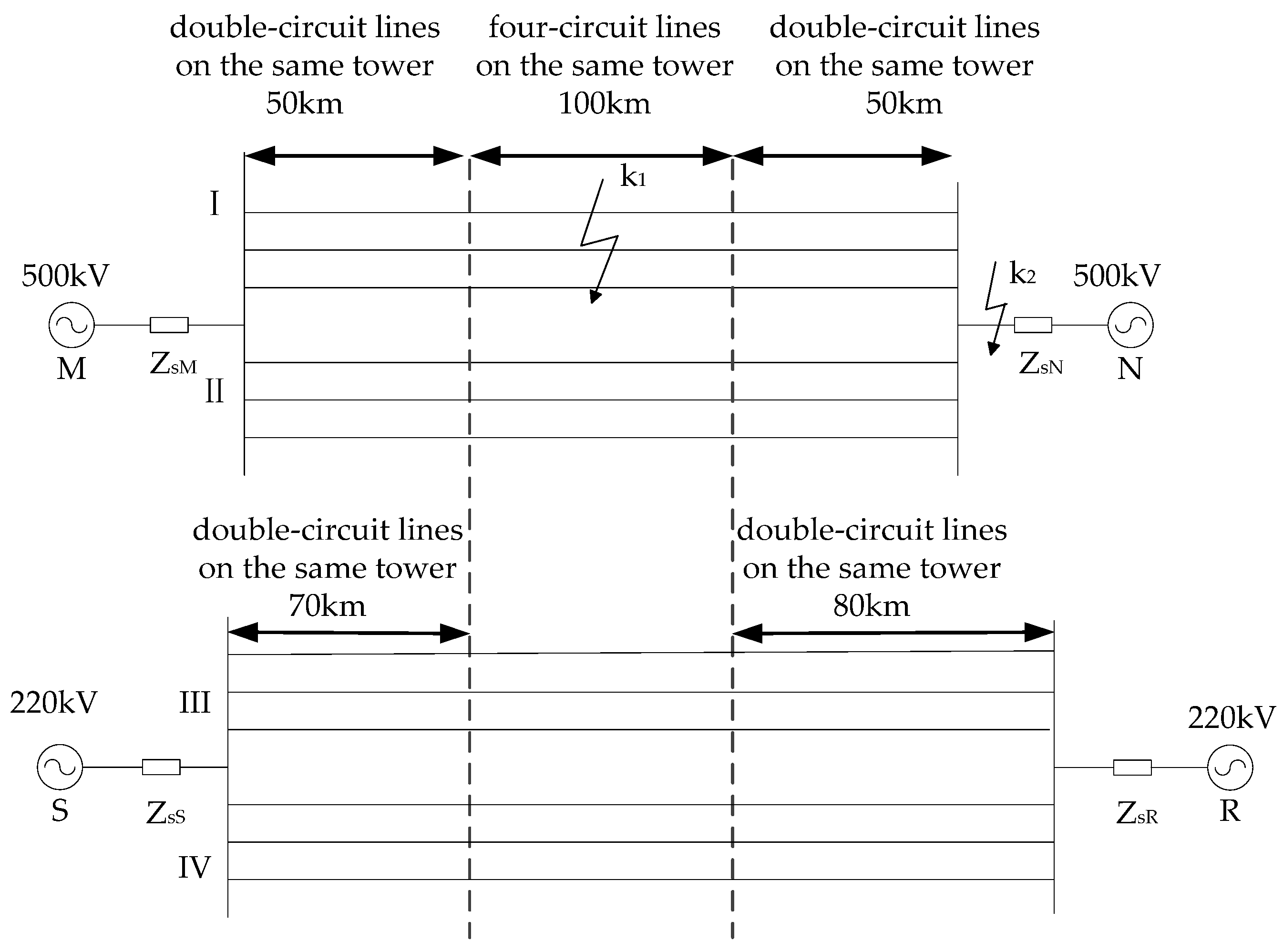
To verify the effectiveness of the method proposed in this paper, models of a 220 kV and 500 kV segment four-circuit lines on the same tower were taken for examples. A distributed parameter simulation model of a 500 kV two-machine system was built, as shown in Figure 4, which was complete transposition. The total length of the 500 kV transmission line was 200 km, the type of conductor was 4 × LGJ-630/45, the total length of a 220 kV transmission line was 250 km, the type of conductor was 2 × LGJ-630/45, the diameter of sub-conductor was 33.6 mm, the split spacing was 500 mm, and the DC resistance at 20 °C was 0.0459 Ω/km. The ground wire of the 500 kV and 220 kV transmission line was optical power ground wire (OPGW), the diameter of the ground wire was 15.6 mm, and the DC resistance at 20 °C was 0.324 Ω/km.
The spatial structure and arrangement of lines on the same tower are shown in Appendix B.
The line length of part of the four-circuit lines on the same tower was 100 km, the line length of part of the double-circuit lines on the same tower was 50 km, and was 70 km and 80 km, respectively.
The system parameters in normal operation mode were as follows. The positive-sequence impedance of the equivalent source M ZsM1 = 27.8∠87.5° Ω, the zero-sequence impedance of the equivalent source M ZsM0 = 83.6∠89° Ω, the positive-sequence impedance of the equivalent source N ZsN1 = 22.24∠87.5° Ω, the zero-sequence impedance of the equivalent source N ZsN0 = 66.88∠89° Ω (the actual value in 500 kV) ,the phase angle difference between the equivalent source M and N is 30°; the positive-sequence impedance of the equivalent source S ZsS1 = 28.7∠84.5° Ω,the zero-sequence impedance of the equivalent source S ZsS0 = 83.3∠89° Ω, the positive-sequence impedance of the equivalent source R ZsR1 = 28.7∠84.5° Ω,the zero-sequence impedance of the equivalent source R ZsR0 = 83.3∠89° Ω (the actual value in 220 kV), phase angle difference between the equivalent source S and R is 20°.
Take this case as an example in the simulation to verify the compensation scheme positive-sequence and zero-sequence distributed capacitance.
4.2. Analysis of Positive and Negative Sequence Capacitance Current Compensation Scheme
From the theory presented in Section 2, with complete transposition in the transmission lines, the parameters of each line are symmetrically. The positive-sequence and negative-sequence capacitance parameters of each line were independent, there was the change of operation modes of the complex four-circuit lines on the same tower had no effect on the positive and negative sequence capacitance current compensation.
To simulate the single-circuit, double-circuit and four-circuit compensation , respectively, when external (k2) two-phase short circuit fault of complex four-circuit lines on the same tower occurred in 0.4 s under different operation modes, there was no zero sequence component in the line current. Take the M1, M2, M3, M4 and M5 operation modes (OM) and the BC two-phase short circuit occurred in the circuit line I region as the example, the three-phase differential current when the external two-phase short circuit fault occurred at the complex four-circuit lines on the same tower under different operation modes are shown in Table 1.
The simulation results demonstrated that the compensation effect on the positive and negative-sequence capacitance current was almost identical under the different operation modes, and the effect of compensation on the four-circuit lines was obviously better than that of the single-circuit and double-circuit lines, therefore a change in operation modes of the complex four-circuit lines on the same tower had no effect on the positive-sequence and negative-sequence capacitance current compensation. However, the zero-sequence capacitance current was still affected by variation of the operating mode when compensated on four-circuit lines.
4.3. Analysis of Zero-Sequence Capacitance Current Compensation Scheme
From the theory presented in Section 2, with complete transposition in the transmission lines and the line parameter symmetrically, the zero-sequence capacitive current compensation is affected significantly by the change of operation modes in the complex four-circuit lines on the same tower, so the zero-sequence capacitive current compensation scheme has to be adaptable to different operation modes.
In this paper, when the external (k2) single-phase grounding (AG) of complex four-circuit lines on the same tower occurred in 0.4 s, the zero-sequence capacitive current was compensated on the double-circuit and four-circuit lines (consider M2 and M3 operation mode), respectively under the five operation modes (OM) of M1, M2, M3, M4 and M5 by using PSACD and MATLAB simulation software.
The three-phase differential current is shown in Table 2, when the external single-phase grounding fault occurred at the complex four-circuit lines on the same tower under different operation modes.
From Table 2, it can be seen that the compensation effect of the complex four-circuit lines on the same tower based on the four-circuit compensation was better than that of the double-circuit compensation. In accordance with four-circuit transmission line compensation, regardless of method to compensate the zero-sequence capacitance current (consider M2 and M3 operation mode), the phase segregated current differential protection effect was not large in the different operation modes.
The zero-sequence differential current is shown in Table 3 when the external single-phase grounding fault occurred at the complex four-circuit lines on the same tower under different operation modes.
From Table 3, the simulation results indicate that the zero sequence capacitive current compensation effect of different operation modes are quite varied, and the zero-sequence capacitance current compensation is affected by the variations in the line operation mode. In other words, a change in operation modes affected the zero-sequence capacitive current compensation significantly. For the zero-sequence current differential protection, when compensating on four-circuit, the compensation effect of the complex four-circuit lines on the same tower based on the M2 operation mode is superior to that of the M3 operation mode. Therefore, when in M4 operation mode, it can also be assumed that the zero-sequence voltage of the different voltage level line is zero, based on the M2 operation mode to compensate the zero-sequence current; when in M5 operation mode, it can be assumed that different voltage levels of the double-circuit line zero-sequence voltage is zero, according to the M2 operation mode to compensate the zero-sequence current.
5. Conclusions
In this paper, we used the complex four-circuit lines on the same tower as an example, and through the theoretical analysis and simulation calculation, we analyzed the circuit operation mode effect on current differential protection capacitance current compensation, and put forward a suitable capacitance current compensation scheme of complex four-circuit lines on the same tower to obtain the following conclusions.
- (1)
- The simulation result indicated that the compensation effect on the positive and negative sequence capacitance current was almost the same under different operation modes. Furthermore, as the effect of compensation on four-circuit lines was obviously better than that of the single-circuit and double-circuit lines, the change of operation modes of the complex four-circuit lines on the same tower had no effect on the positive-sequence and negative-sequence capacitance current compensation. However, the zero-sequence capacitance current was still affected by the variation of the operating mode when compensated on four-circuit lines.
- (2)
- Based on the characteristics of the zero-sequence capacitance under different operating conditions, the setting value of the zero-sequence capacitance current compensation could be adjusted as per different operation modes, to meet the switching of different operation modes. This switching method can ensure the selectivity of current differential protection and can also improve the action sensitivity of the phase differential protection.
- (3)
- For phase segregated current differential protection, the compensation method can be carried out as per four lines in parallel operation on the same tower. For zero sequence current differential protection, it can be used to compensate the zero sequence current based on the M2 operation mode.
Acknowledgments
This work was supported in part by the key project of smart grid technology and equipment of National Key R&D Program of China (2016YFB0900600).
Author Contributions
All authors have contributed in the article. Cui Tang and Xianggen Yin participated in initial discussion for deciding the methodology and wrote the paper. Cui Tang performed all the simulation work, gathered important results, and analyzed the data and results. Zhe Zhang contributed analysis tools. The main reviews were done by all authors before finalizing the final draft.
Conflicts of Interest
The authors declare no conflict of interest.
Appendix A
The process of derivation and analysis under other operating conditions are shown as follows.
- (1)
- One circuit line is in normal operation and the other three circuit lines are disconnected.
When circuit line I is running normally, circuit lines II, III and IV are disconnected. The charge of circuit lines II, III and IV is zero, that is , , , there are
Put Equation (A1) into Equation (14), and the zero-sequence capacitance of circuit line I is .
- (2)
- One circuit line is in normal operation, two circuit lines are disconnected, and one circuit line is grounded for maintenance.
When circuit line I is running normally, circuit lines II and III are disconnected, and circuit line IV is grounded for maintenance, the charge of circuit lines II and III is zero, that is, , . The potential of circuit line IV is zero, that is ,
Put Equation (A2) into Equation (14), and the zero-sequence capacitance of circuit line I is .
- (3)
- One circuit line is in normal operation, one circuit line is disconnected, and two circuit lines are grounded for maintenance.
When circuit line I is running normally, circuit line II is disconnected, and circuit lines III and IV are grounded for maintenance, the charge of circuit line II is zero, that is . The potential of circuit lines III and IV is zero, that is, ,
Put Equation (A3) into Equation (14), and the zero-sequence capacitance of circuit line I is .
- (4)
- Two lines are in normal operation, one is grounded for maintenance, and another is disconnected.
Assume that circuit line I and II is running normally, circuit line III is grounded for maintenance, and circuit line IV is disconnected. The potential of circuit line III is zero, that is, . The charge of circuit lines III and IV is zero, that is .
Put Equation (A4) into Equation (14), and the zero-sequence capacitance of circuit line I is . The zero-sequence capacitance of circuit line II is .
- (5)
- Three lines are in normal operation and the other circuit line is disconnected.
Assume that circuit line I, II and III are in parallel operation, and circuit line IV is disconnected. The charge of circuit line IV is zero, that is, ,
For the four-circuit lines on the same tower, when circuit lines I, II and III are in parallel operation, if the two sets of double loop are the whole lines on the same tower, it is considered that the zero-sequence voltage of circuit line II is the same as the zero-sequence voltage of circuit line I when fault occurs in circuit line I and the zero-sequence voltage of circuit III transmission lines in the other group is zero, the zero sequence capacitance of circuit I is , the zero-sequence capacitance of circuit line II is .
Appendix B
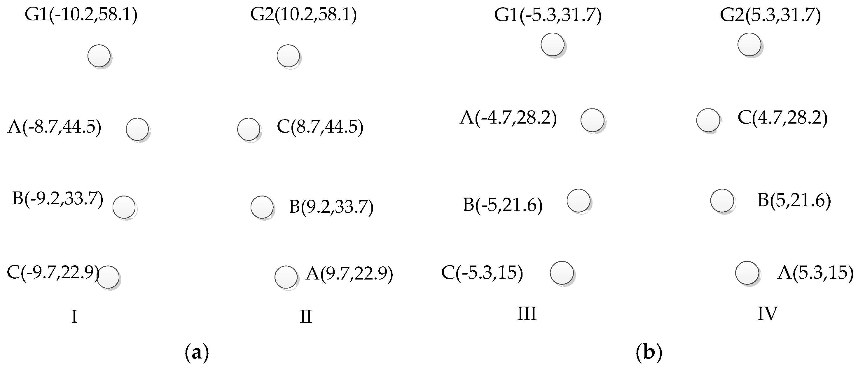
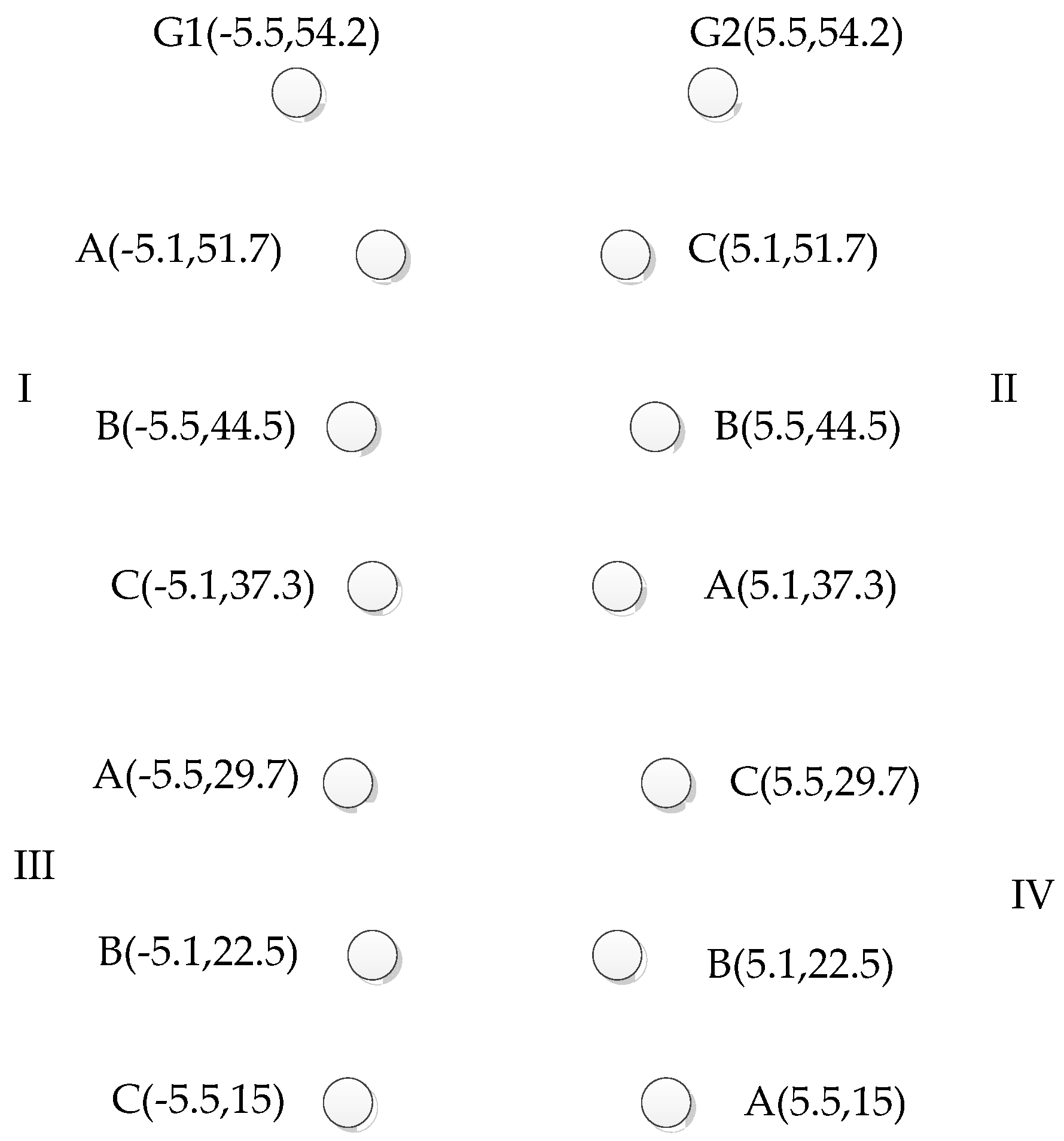
The wire layout and sequence arrangement of four-circuit lines on the same tower and double-circuit lines on the same tower in the simulation model are shown in Figure B1 and Figure B2, respectively.
Figure B1.
Four-circuit lines on the same tower conductor arrangement diagram.

Figure B2.
Arrangement of conductors of double-circuit lines on the same tower: (a) 500 kV double-circuit lines on the same tower; and (b) 220 kV double-circuit lines on the same tower.
Figure B2.
Arrangement of conductors of double-circuit lines on the same tower: (a) 500 kV double-circuit lines on the same tower; and (b) 220 kV double-circuit lines on the same tower.
References
- Feng, G.; Wang, Y.; Zhang, B. Study on electromagnetic environment of multi-circuit transmission lines on same tower. Proceedings of 2008 Joint International Conference on Power System Technology and IEEE Power India Conference, New Delhi, India, 12–15 October 2008. [Google Scholar]
- Novitskiy, A.; Westermann, D. Interaction of multi-circuit overhead transmission lines of different voltages located on the same pylons. Proceedings of 2012 Electric Power Quality and Supply Reliability Conference (PQ), Tartu, Estonia, 11–13 June 2012. [Google Scholar]
- Song, G.; Suonan, J.; Xu, Q.; Chen, P.; Ge, Y. Parallel transmission lines fault location algorithm based on differential component net. IEEE Trans. Power Deliv. 2005, 20, 2396–2406. [Google Scholar] [CrossRef]
- Wang, X.; Xu, L.; Zhang, X. Line protection feature study on four-circuit transmission lines on a same tower. Autom. Electr. Power Syst. 2007, 31, 80–85. (In Chinese) [Google Scholar]
- Xu, Z.Y.; Du, Z.Q.; Ran, L.; Wu, Y.K.; Yang, Q.X.; He, J.L. A current differential relay for a 1000-kV UHV transmission line. IEEE Trans. Power Deliv. 2007, 22, 1392–1399. [Google Scholar] [CrossRef]
- Sachdev, M.S.; Sidhu, T.S.; Liu, X. High-speed differential protection of parallel teed transmission lines. Proceedings of IEEE Wescanex ′95 Communications, Power, and Computing Conference, Winnipeg, MB, Canada, 15–16 May 1995. [Google Scholar]
- Guo, Z.; He, G. Novel principle of pilot differential relay protection of transmission lines. Autom. Electr. Power Syst. 2004, 28, 1–5. (In Chinese) [Google Scholar]
- Chen, J.; Fan, C.; Liu, L. New longitudinal differential protection scheme for four-circuit transmission line with different voltage grades. Power Syst. Prot. Control 2011, 39, 72–79. (In Chinese) [Google Scholar]
- Zheng, Y.P.; Wu, T.H.; Ding, Y.; Chen, Y. Applied criterion of current differential protection based on bergeron model. Autom. Electr. Power Syst. 2004, 28, 50–55. (In Chinese) [Google Scholar]
- Rane, P.S.; Jawale, R.D.; Bhaisare, S.D.; Debre, P.D. Impact of capacitive current of EHV/UHV lines on current differential protection. Proceedings of 2016 International Conference on Energy Efficient Technologies for Sustainability (ICEETS), Nagercoil, India, 7–8 April 2016. [Google Scholar]
- Bi, T.S.; Yu, Y.L.; Huang, S.F.; Yang, Q.X. An Accurate compensation method of distributed capacitance current in differential protection of UHV transmission line. In Proceedings of the 2005 IEEE Power Engineering Society General Meeting, San Francisco, CA, USA, 12–16 June 2005. [Google Scholar]
- Li, Y.; Chen, D.S.; Zhang, Z.; Yin, X. The emulation analysis for the influence of capacitance current of UHV transmission line on differential current protection and compensating countermeasure. Relay 2001, 29, 6–9. (In Chinese) [Google Scholar]
- Zhang, Y.; Suonan, J.; Xu, B.; Jiao, Z. Current differential protection using time-domain compensation of capacitive current. Proceedings of 7th IET International Conference on Advances in Power System Control, Operation and Management, Hong Kong, China, 30 October–2 November 2006. [Google Scholar]
- Zhang, Q.; Tai, N.; Yuan, C.; Chen, K. Analysis of capacitance current compensation of current differential protection on four-parallel lines. Autom. Electr. Power Syst. 2010, 34, 46–50. (In Chinese) [Google Scholar]
- Zhang, Y.; Jiale, S. Phaselet-based current differential protection scheme based on transient capacitive current compensation. IET Gener. Transm. Distrib. 2008, 2, 469–477. [Google Scholar]
- Yang, Y.; Yin, X.; Tang, C.; Zhang, Z.; Wang, X. Research on capacitive current compensation for current differential protection of segment parallel lines for different voltage levels. Proceedings of 2015 5th International Conference on Electric Utility Deregulation and Restructuring and Power Technologies (DRPT), Changsha, China, 26–29 November 2015. [Google Scholar]
- Wang, X.T.; Wang, C.C.; Jiang, W.D. Research on capacitance current compensation of differential protection on double-parallel lines. Energy Eng. 2013, 1, 26–30. [Google Scholar]
Figure 1.
Half-length compensation schematic diagram.

Figure 2.
Capacitance distribution of the complex four-circuit lines on the same tower.

Figure 3.
Simplified model of capacitance distribution between complex four-circuit lines on the same tower.
Figure 3.
Simplified model of capacitance distribution between complex four-circuit lines on the same tower.

Figure 4.
Simulation model of complex four-circuit lines on the same tower.


Table 1.
Three-phase differential current under different operation modes.
| OM | No Compensated /kA | Compensated on Single-Circuit /kA | Compensated on Double-Circuit /kA | Compensated on Four-Circuit /kA | ||||||||
|---|---|---|---|---|---|---|---|---|---|---|---|---|
| A | B | C | A | B | C | A | B | C | A | B | C | |
| M1 | 0.197 | 0.097 | 0.124 | 0.044 | 0.021 | 0.028 | 0.027 | 0.012 | 0.018 | 0.001 | 0.001 | 0.001 |
| M2 | 0.199 | 0.094 | 0.119 | 0.045 | 0.020 | 0.028 | 0.028 | 0.013 | 0.018 | 0.001 | 0.002 | 0.002 |
| M3 | 0.199 | 0.943 | 0.119 | 0.045 | 0.020 | 0.028 | 0.028 | 0.011 | 0.018 | 0.001 | 0.002 | 0.002 |
| M4 | 0.199 | 0.094 | 0.119 | 0.045 | 0.020 | 0.028 | 0.028 | 0.011 | 0.018 | 0.001 | 0.002 | 0.002 |
| M5 | 0.200 | 0.095 | 0.117 | 0.046 | 0.021 | 0.026 | 0.029 | 0.012 | 0.016 | 0.003 | 0.003 | 0.002 |
Table 2.
Three-phase differential current under different operation modes
| OM | No Compensated/kA | Compensated on Double-Circuit /kA | Compensated on Four-Circuit (on Operation Mode M2) /kA | Compensated on Four-Circuit (on Operation Mode M3) /kA | ||||||||
|---|---|---|---|---|---|---|---|---|---|---|---|---|
| A | B | C | A | B | C | A | B | C | A | B | C | |
| M1 | 0.078 | 0.205 | 0.217 | 0.012 | 0.044 | 0.047 | 0.023 | 0.023 | 0.023 | 0.026 | 0.027 | 0.025 |
| M2 | 0.099 | 0.197 | 0.203 | 0.012 | 0.028 | 0.029 | 0.001 | 0.001 | 0.002 | 0.002 | 0.003 | 0.002 |
| M3 | 0.101 | 0.197 | 0.201 | 0.014 | 0.027 | 0.028 | 0.002 | 0.002 | 0.003 | 0.001 | 0.002 | 0.001 |
| M4 | 0.099 | 0.198 | 0.201 | 0.013 | 0.028 | 0.028 | 0.002 | 0.001 | 0.002 | 0.002 | 0.002 | 0.001 |
| M5 | 0.100 | 0.199 | 0.200 | 0.013 | 0.029 | 0.026 | 0.003 | 0.002 | 0.003 | 0.003 | 0.002 | 0.002 |
Table 3.
Zero-Sequence differential current under different operation modes
| Operation Mode | No Compensated /kA | Compensated on Double-Circuit /kA | Compensated on Four-Circuit (on Operation Mode M2) /kA | Compensated on Four-Circuit (on Operation Mode M3) /kA |
|---|---|---|---|---|
| M1 | 0.17383 | 0.08964 | 0.06836 | 0.07705 |
| M2 | 0.104184 | 0.018834 | 0.003154 | 0.006826 |
| M3 | 0.099445 | 0.014962 | 0.006635 | 0.003247 |
| M4 | 0.102194 | 0.016992 | 0.009044 | 0.006544 |
| M5 | 0.099969 | 0.015887 | 0.005261 | 0.005265 |
© 2017 by the authors. Licensee MDPI, Basel, Switzerland. This article is an open access article distributed under the terms and conditions of the Creative Commons Attribution (CC BY) license (http://creativecommons.org/licenses/by/4.0/).
Share and Cite
MDPI and ACS Style
Tang, C.; Yin, X.; Zhang, Z. Research on Capacitance Current Compensation Scheme of Current Differential Protection of Complex Four-Circuit Transmission Lines on the Same Tower. Energies 2017, 10, 1071. https://doi.org/10.3390/en10071071
AMA Style
Tang C, Yin X, Zhang Z. Research on Capacitance Current Compensation Scheme of Current Differential Protection of Complex Four-Circuit Transmission Lines on the Same Tower. Energies. 2017; 10(7):1071. https://doi.org/10.3390/en10071071
Chicago/Turabian StyleTang, Cui, Xianggen Yin, and Zhe Zhang. 2017. "Research on Capacitance Current Compensation Scheme of Current Differential Protection of Complex Four-Circuit Transmission Lines on the Same Tower" Energies 10, no. 7: 1071. https://doi.org/10.3390/en10071071
Note that from the first issue of 2016, this journal uses article numbers instead of page numbers. See further details here.