1. Introduction
1.1. Engine Thermal Overload
The last couple of decades has seen a steady improvement of the power output from slow speed diesel engines with increase of propulsion power demands [
1,
2,
3]. This has pushed engine researchers to increase the engine power density and reduce the specific fuel oil consumption (SFOC) [
4,
5]. An increase in power output from the cylinder results in an increase in fuel consumption. And the SFOC reduction can be achieved by operating the engine closer to stoichiometric conditions and keeping all the other parameters unchanged [
3]. This has resulted in a reduction in design margins for the engines with higher component temperatures. However operating the engine closer to a thermal overload condition will reduce the operating life of combustion chamber components and may cause catastrophic failure in some instances [
6,
7].
1.2. Current Engine Monitoring Technology Development
As diesel engine technology is advancing, increased use of use of analytical methods has proven necessary to establish monitoring techniques able to predict performance and identify faults in the engine. The most common parameters used to monitor the thermodynamic performance of an engine are pressure and temperature at various points on the cycle, which can be found widely in the literature around engine research [
8,
9,
10,
11,
12,
13].
The most widely used technique for in-situ monitoring is a pressure volume trace, a technology historically referred to as an indicator card [
14,
15,
16,
17]. It is used to calculate the indicated power developed by a cylinder and when used with a light spring version, visualises the gas exchange process. The indicator instrument is used to obtain an out of phase diagram, commonly referred to as ‘draw card’, which helps detect faults during the injection and combustion period. This technique can fail to indicate certain faults in the thermodynamic process. It is because the technique relies on measuring pressure which is a function of temperature and has its limitations when it comes to monitoring present day diesel engines operating with lower air to fuel ratio. This can be explained in simple terms, if the mass of air and volume are kept constant then a 100 °C change in maximum cycle temperature will change the pressure by a factor of 1.04 which is small and cannot be detected on an indicator diagram with absolute certainty.
When operating closer to stoichiometric conditions, dissociation (an endothermic reaction that breaks the products back to reactants) takes place which reduces the cycle temperature. Therefore, significant changes in temperature and subsequently pressure are not observed. However, in a diesel engine cylinder with non-uniform air to fuel ratio across the cylinder the rate of combustion slows down in regions where the air-fuel mixture is rich. This influences the size of the flame and combustion period, increasing the rate of heat transfer to the combustion chanter components. It is not possible to identify such faults with the diagrams obtained from indicator instruments.
1.3. Aims and Objectives
In this research, the development of a diesel engine thermal overload monitoring system is presented with applications and test results. Due to the limitation in conventional monitoring techniques for diesel engines, the requirement here is to develop a monitoring technique that can predict the air to fuel ratio within individual cylinders which will help engineers monitor the status of the engine thermal condition.
2. Diesel Engine Thermal Overload
Then the hypothesis for the most probable cause of thermal overload condition on diesel engines is summarised as:
- (1)
A low λ (excess air) ratio is the most probable cause of voluminous flame production, and there is an increase in flame size.
- (2)
A high surface temperature of engine component is caused by voluminous flame.
To validate the hypothesis above, experiments were undertaken to investigate the effect of
λ ratio on flame size and temperature, and the effect of voluminous flame on component surface temperature. Detailed analysis of the thermal overload in diesel engines can be found in [
18].
The flame visualisation test rig was manufactured using a pair of inter-connected combustion chambers. Combustion in this test rig was therefore used to replicate uniflow scavenged two stroke diesel engine combustion, with the trapped air to fuel ratio indicating conditions in the primary chamber and overall air to fuel ratio indicating condition across the combustor. During the course of initial testing with constant air flow rate and increasing levels of sub-stoichiometry it was observed that the flame lift off distance from the burner increased and the luminous flame became more voluminous.
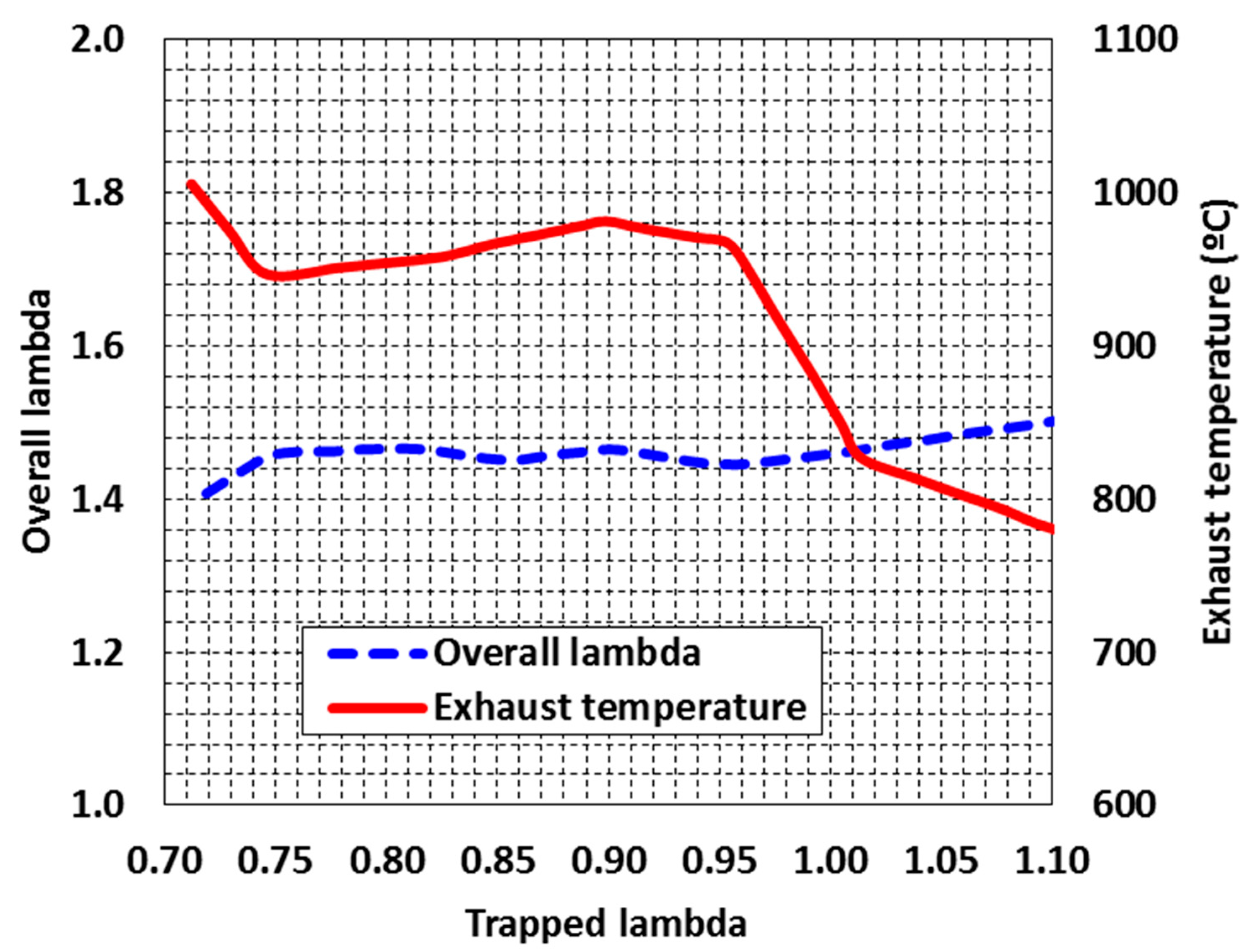
Figure 1 can be used to explain the structure of the flame at different
λ. An indication that this has occurred will be an increase in exhaust temperature at the outlet probe as a results of closer proximity of the flame. The temperature at the probe increased from 775 °C to 1000 °C with
λ changing from 1.12 to 0.71. This high temperature flame when close to or in contact with any combustion chanter component will result in an increased rate of heat transfer through the component and its consequent failure. Detailed information on the test rig development and test results analysis can be found in [
18].
Piston crown temperature estimation was carried out on a 7RTA847 engine (Sulzer, Winterthur, Switzerland) where high rates of hot corrosion were evident on a unit and also on a unit where piston crown wear rates were normal.
Figure 2a shows the thermal paint applied to the surface of the piston crown prior to the trial.
Figure 2b shows the color shades on completion of the trial on the piston crown with the highest wear rate, which is very close to Matt Glaze and the surface temperatures around the hot zone, are probably much in excess of the design temperature. A comparison of the thermal paint results for best and worst crown (
Figure 2a,b) show that the latter with normal ware rate has a dusty grey shade with yellowish tinge at places. Hot corrosion could have been caused by high crown surface temperature coupled with corrosive salt deposits which melt and accelerate inter-granular corrosion. The test results prove that high surface temperature and salt deposition on the crown in the heavily burned away regions could have been caused by flame and fuel impingement respectively. As in an ideal scenario, the flame should be compact and should not come in contact with the piston crown or exhaust valve [
18].
3. Design of the Thermal Overload Monitoring System
3.1. System Design Introduction
In our previous research, the effect of
λ on flame size was observed with tests conducted on a continuous combustion test rig. The flame became voluminous for lambda values of approximately less than 1.2. For compression ignition engines with intermittent combustion, it would occur at higher lambda values but this needs to be confirmed by conducting tests on a diesel engines. As a voluminous flame would increase the surface temperature of combustion chamber components, the most accurate way to validate this would be to measure temperatures on these components for different values of lambda. For a diesel engine, with constant injection timing and expansion ratio, a high flame temperature would result in high exhaust temperature and low oxygen concentration. This gives the possibility of predicting the size of the flame based on oxygen concentration and temperature of the blow-down gas. The proposed engine thermal overload monitoring system mainly consists two types of sensors, a lambda sensor and a fast response thermocouple. The lambda sensor is used to measure the oxygen concentration in the blow down gas, and the fast response thermocouple is adopted to measure the exhaust temperature. Other sensors for example crank angle sensor etc. are adopted for analysis of the engine operation performance. Cylinder pressure sensors are also used to assist to identify faults [
19].
3.2. Calculation of Oxygen Concentration in the Blow Down Gas
In the previous section it has been identified that a voluminous flame in the vicinity of combustion chamber components will result in high thermal stress and this will be dependent on the flame temperature. Meanwhile, voluminous flame produces at low oxygen concentration. Therefore, it is necessary to establish a relationship between lambda and the oxygen concentration in the blow down gas leaving the cylinder. A simple calculation is made for a steady flow constant pressure combustion chamber operating on gas oil. Stoichiometric air demand for the fuel is 14.9 kg and it combustion is assumed to be complete, the products will be CO
2, H
2O and N
2. The general combustion equation, where
λ is the excess air ratio is given by:
An elemental balance of the reactants and products returns the following molar volumes of the products of combustion: b = 12; c = 13; d = 18.5 × (λ − 1).
Then the oxygen concentration in the exhaust gas,
can be represented by:
Substituting
,
,
yields:
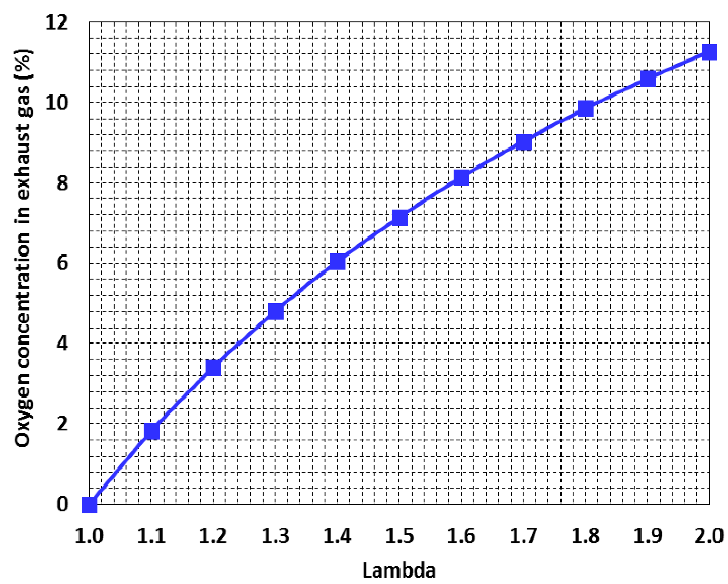
The data shown in
Figure 3 demonstrated the oxygen concentration in the blow down gas using Equation (3).
The gas exchange process in a diesel engine is a phase during which the products of combustion from a cylinder are removed and replaced with a fresh charge of at for the subsequent combustion cycle. For a four stroke engine this process takes place in two dedicated strokes while in a two stroke engine this process takes place within a few rotational crank angle degrees around bottom dead centre. The air lost during this process is insignificant, and the difference between trapped and overall air to fuel ratio is not significant. Overall air to fuel ratios for medium speed four stroke engines will be in the range of 1.8 to 2.2. As a result, the overall lambda value for the sub-stoichiometric condition of the four stroke diesel engine would be lower than 1.8, which corresponds to an oxygen concentration of lower than 9% from
Figure 3. Thus, when the detected oxygen concentration in the exhaust gas is lower than 9%, it will be of high possibility for the engine to be operated in a thermal overload condition.
3.3. Thermal Overload Monitoring System
3.3.1. Pressure and Oxygen Sensors
One of the most effective ways to monitor the performance and condition of an engine is by analysing the pressure of the gas in the cylinder throughout the combustion cycle [
20]. Piezoelectric pressure sensors that measure pressure change in the cylinder are used in conjunction with a crank angle sensor to provide piston position and cylinder volume data [
21]. The measurement of oxygen concentration in engine exhaust is widely used in the automotive industry on spark ignition gasoline engine for fuel regulation and is commonly known as the Lambda sensor. A lambda sensor capable of measuring a wide band of oxygen concentration has been obtained from Bosch (Gerlingen, Germany) and is capable of measuring from very high lambda values down to 0.65. Its response time of 5 ms makes its suitable for use as a diagnostic tool for slow and medium speed diesel engine.
The wide band sensor operates in conjunction with a special control unit which acts as an interface between the operator and the diagnostic system. This interface is an ETAS LA4 lambda meter (Stuttgart, Germany), a precision measuring instrument which permits cost effective measurement of exhaust gases in gasoline, diesel and gas engines in conjunction with the broadband lambda sensors. The instrument uses fuel specific maps to convert the oxygen content and can display both the current
λ values and the air fuel ratio. The instrument permits the measurement of the following parameters shown in
Table 1.
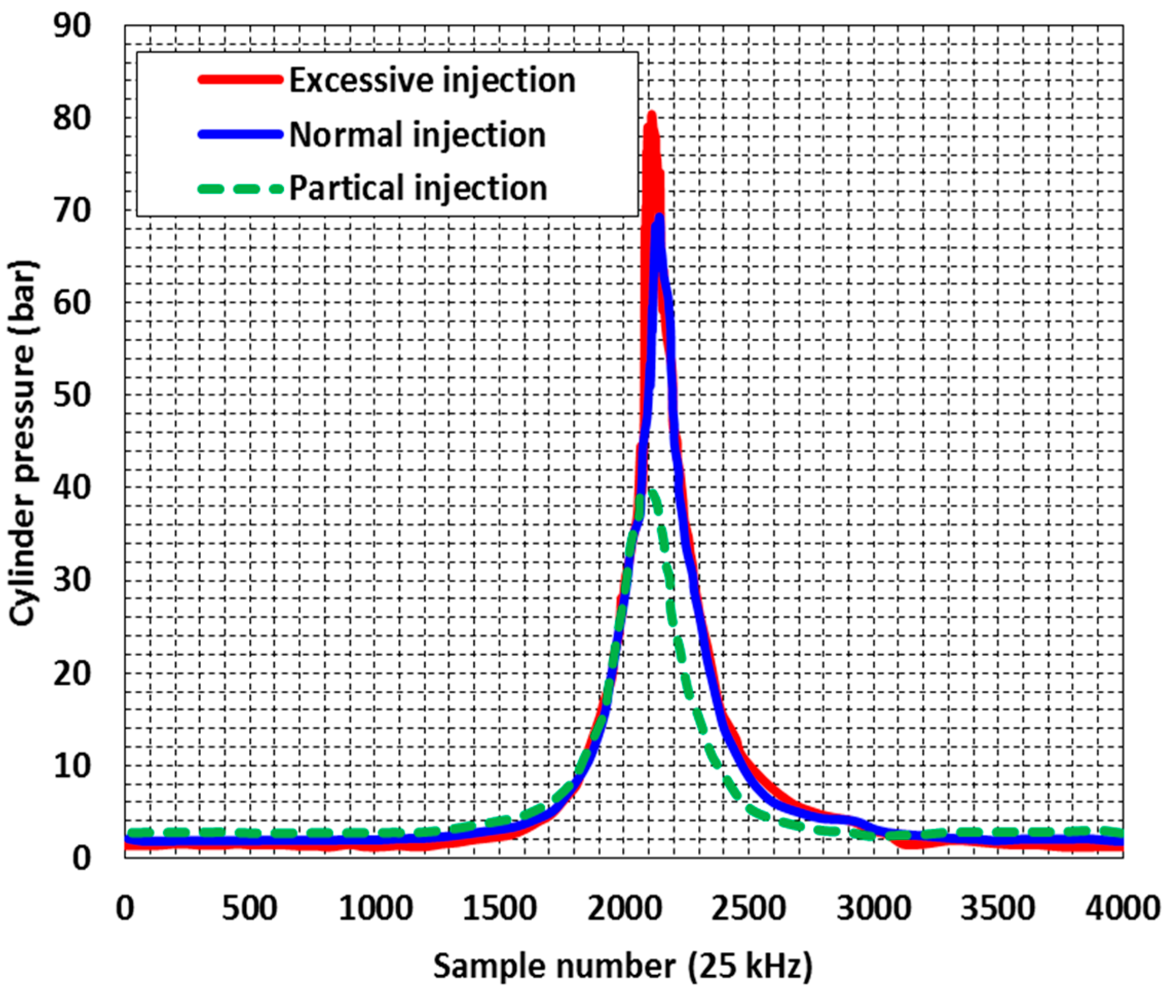
To check the effectiveness of the system for use on a slow speed diesel engine, a test for proof of concept was conducted on a medium speed Ruston diesel engine in the Jones Marine Engineering laboratory. With the engine running at a constant speed of 720 rpm and load of 500 kW, three different conditions were simulated: normal, partial, and excessive fuel injections. As the engine was operating with a constant pressure ratio across all the cylinders, it was assumed that each of them will trap approximately the same mass of air for combustion. As the data in
Figure 4 is used to present the pressure difference and verify the effectiveness of the sensing system, detailed analysis is not provided in this paper. It can be seen from
Figure 4 that where excessive fuel injection resulted in a higher peak pressure. Similar patterns were observed with normal and partial fuel injection. Hence, the sensing system will work satisfactorily when used to monitor a slow speed diesel engine.
3.3.2. Fast Response Thermocouple
Temperature is one of the most measured physical parameters for process control and fault diagnosis. The
K-type thermocouple, nickel-chromium versus nickel-aluminium, is the most widely used [
22,
23]. The standard robust thermocouples fitted on diesel engines to monitor exhaust gas temperatures from individual cylinders as part of continuous health monitoring, have their limitations when it comes to critical fault diagnosis. They can be used to identify major and obvious problems, such as loss of compression through a leaking exhaust valve or broken piston rings or any associated problem that results in an increase in steady state exhaust gas temperature. The response time of a temperature sensor is dependent on the thermal properties of the sensor, the heat transfer coefficient, its size and the response time of any signal processing associated with it. In a diesel engine, the temperature of exhaust coming out of the cylinder is not constant and changes dynamically. The selection of a thermocouple type for a particular sensing application, physical condition, duration of exposure, sensor lifetime and accuracy all have to be considered.
The use of very fine thermocouple i.e.,
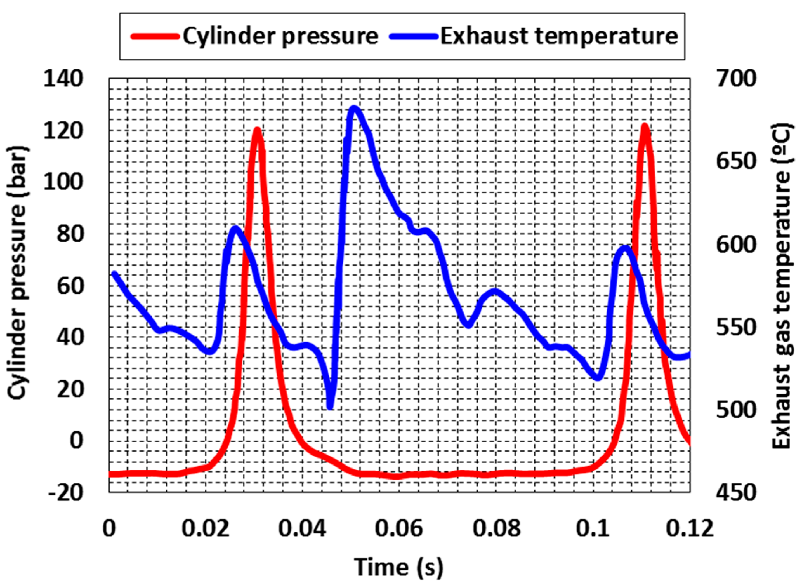
K-type of 0.025 mm inside a ceramic insulating tube, protected by a stainless steel outer tube is tested on a high speed diesel engine operating at 1500 rpm. The entire assembly was shielded to minimise Radio Frequency Interference (RFI) problems and connected to an amplification and temperature compensation circuit. The exposed thermocouple junction has a time constant of 0.004 s in a moving gas. In practice, fabricating these sensors is extremely difficult and time consuming due to the fragile nature of the materials involved.
Figure 5 shows one of these thermocouples in situ on the exhaust manifold between the cylinder and turbocharger. This particular sensor lasted only a few hours before failure due to vibration and the blow down gas temperature exceeding the maximum recommended for a thermocouple for this size, but produced useful results during this time.
It is seen that the temperature of the exhaust gas in the manifold increased sharply after the cylinder pressure pulse at approximately 0.05 s, adjacent to a noticeable drop in cylinder pressure caused by the opening of the exhaust valve. The wave of exhaust gas exiting the cylinder is evidenced by the rapid increase in temperature, and the subsequent shape of the temperature trace is due to the cooling of the exhaust gas as it expands into the manifold. The pressure pulse shows the combustion and the temperature pulse shows the exhaust phase of the cycle. Also seen at approximately 0.03 and 0.8 s are small but significant temperature pulses due to the exhaust exchange process for the adjacent cylinders. The tests were used to demonstrate the possibility of utilising dynamic temperature sensing fault diagnostics.
4. Testing Results of the Thermal Overload Monitoring System
4.1. Test Engine Description
A medium speed Ruston diesel engine was instrumented to measure the required engine process parameters. Testing was carried out using a cylinder pressure sensor and oxygen sensor fitted to cylinder 3. The configurations for the selected engine are listed in
Table 2.
It was expected to identify an engine thermal overload condition with the novel monitoring system. A fast response thermocouple and exhaust valve timing proximity sensors are fitted. The pressure sensor used is a Bosch LSU 4.9 mounted on the exhaust duct between the cylinder head and the common manifold. Two markers, for the start of fuel injection and the piston at top dead centre (TDC) for Cylinder 3, are installed on the flywheel and a proximity sensor mounted to provide the indication. Cylinder pressure and oxygen concentration data is acquired with the aid of a data acquisition card (National Instruments Corporation, Austin, TX, USA) and Matlab post-processing DAQ (Data acquisition) code. All other monitored data was recorded using a Doctor DK 2 data acquisition system developed by Icon Research (West Lothian, UK).
4.2. Thermal Overload Sensing System Set up
Three set of sensors were fitted on the cylinder, a proximity sensor was used to measure exhaust valve timing, a lambda sensor and a fast response thermocouple to measure the oxygen concentration and the temperature of the gas leaving the cylinder respectively. The oxygen concentration profile and the dynamic exhaust gas temperature, recorded with respect to the crank angle during the blow-down and scavenging process, will give an indication of the thermal load, combustion quality and gas exchange process for the cylinder. Digital sensors were mounted on a bracket close to flywheel and adjusted to measure the piston TDC position and operation speed. Although not an integral part of the proposed monitoring system, the cylinder pressure was recorded to establish a co-relation between the trapped lambda values and rate of pressure rise due to combustion. Tapping were fitted upstream and downstream of the turbocharger turbine to measure pressure at inlet and outlet for performance and air flow calculations.
4.3. Initial Test Results and Discussion
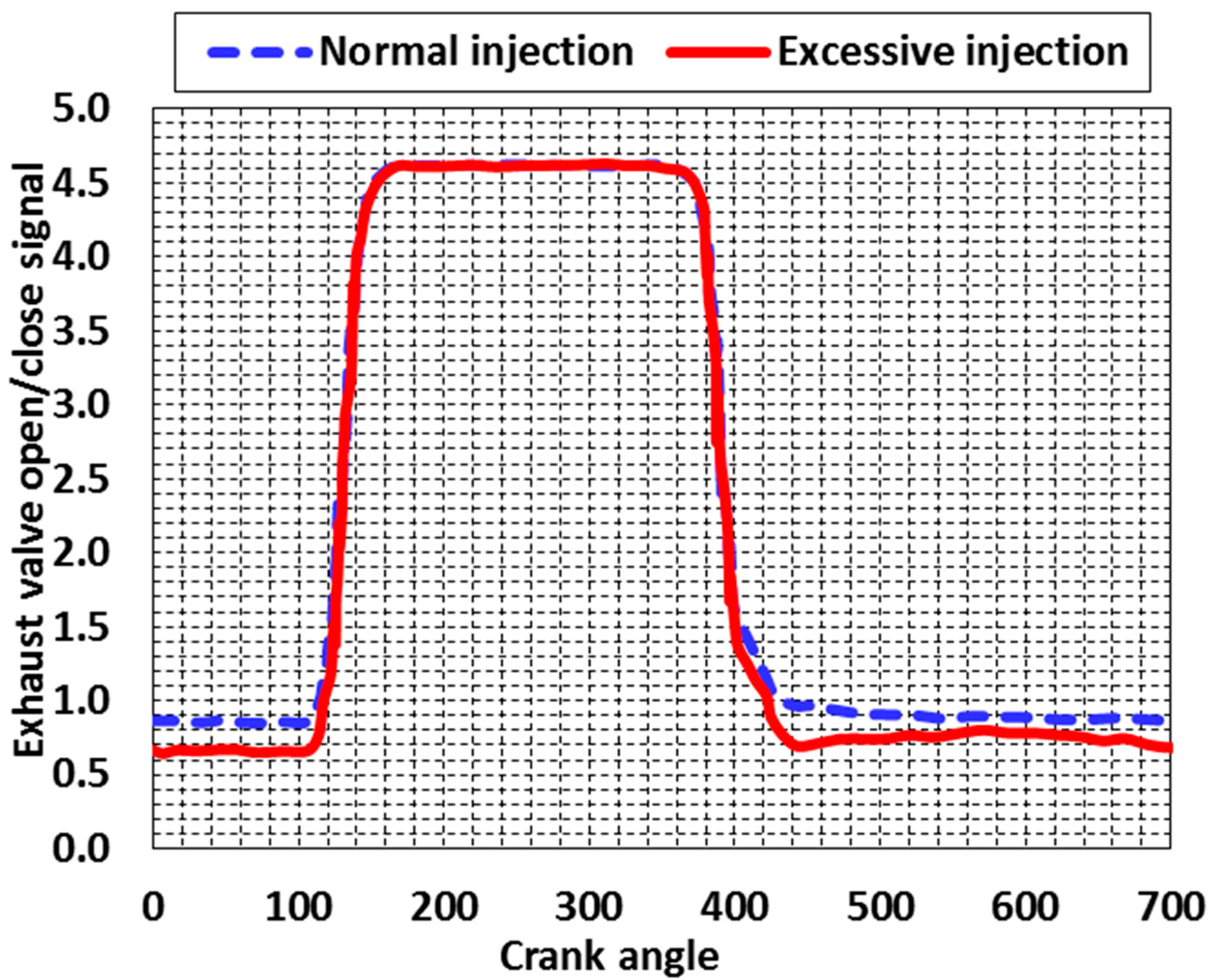
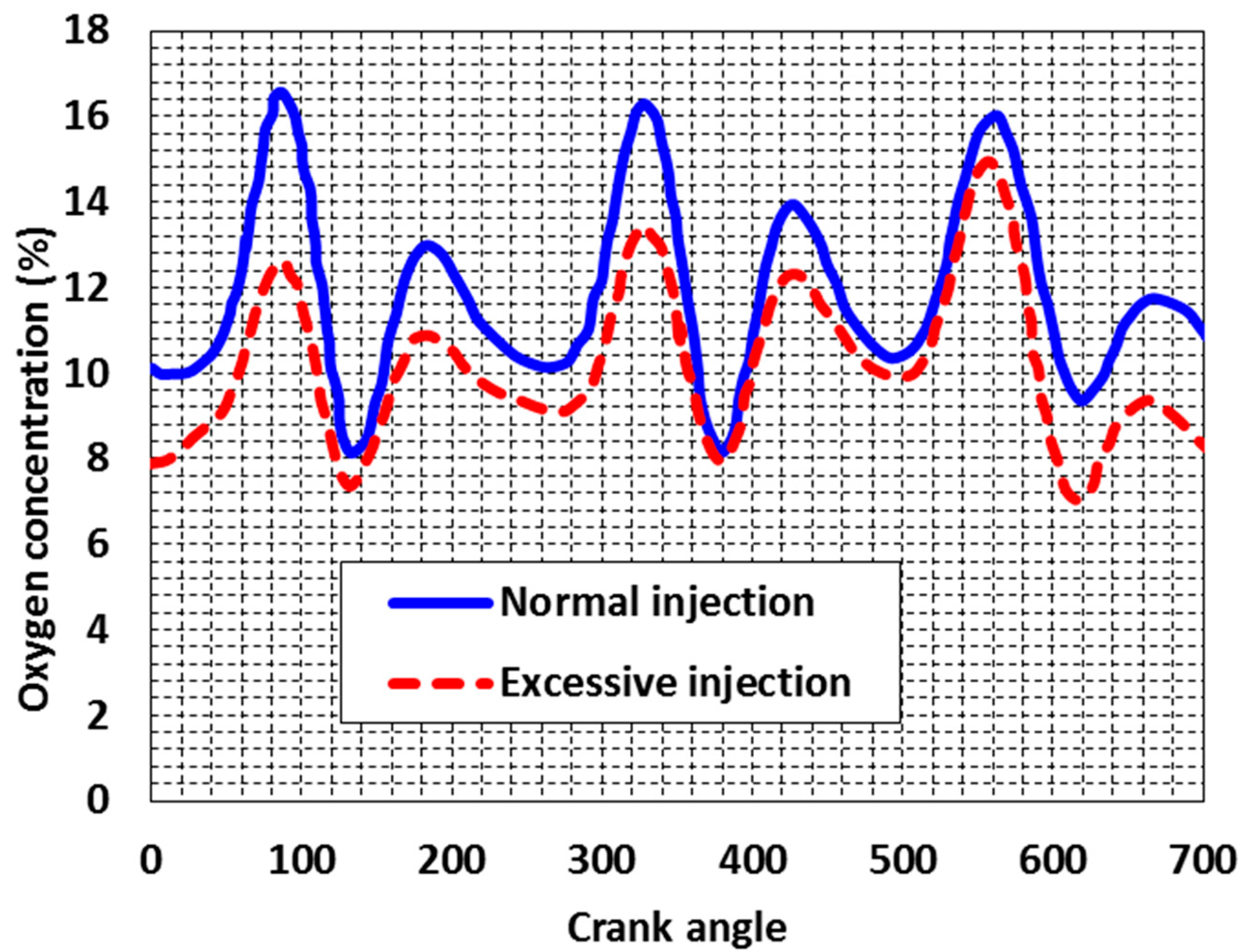
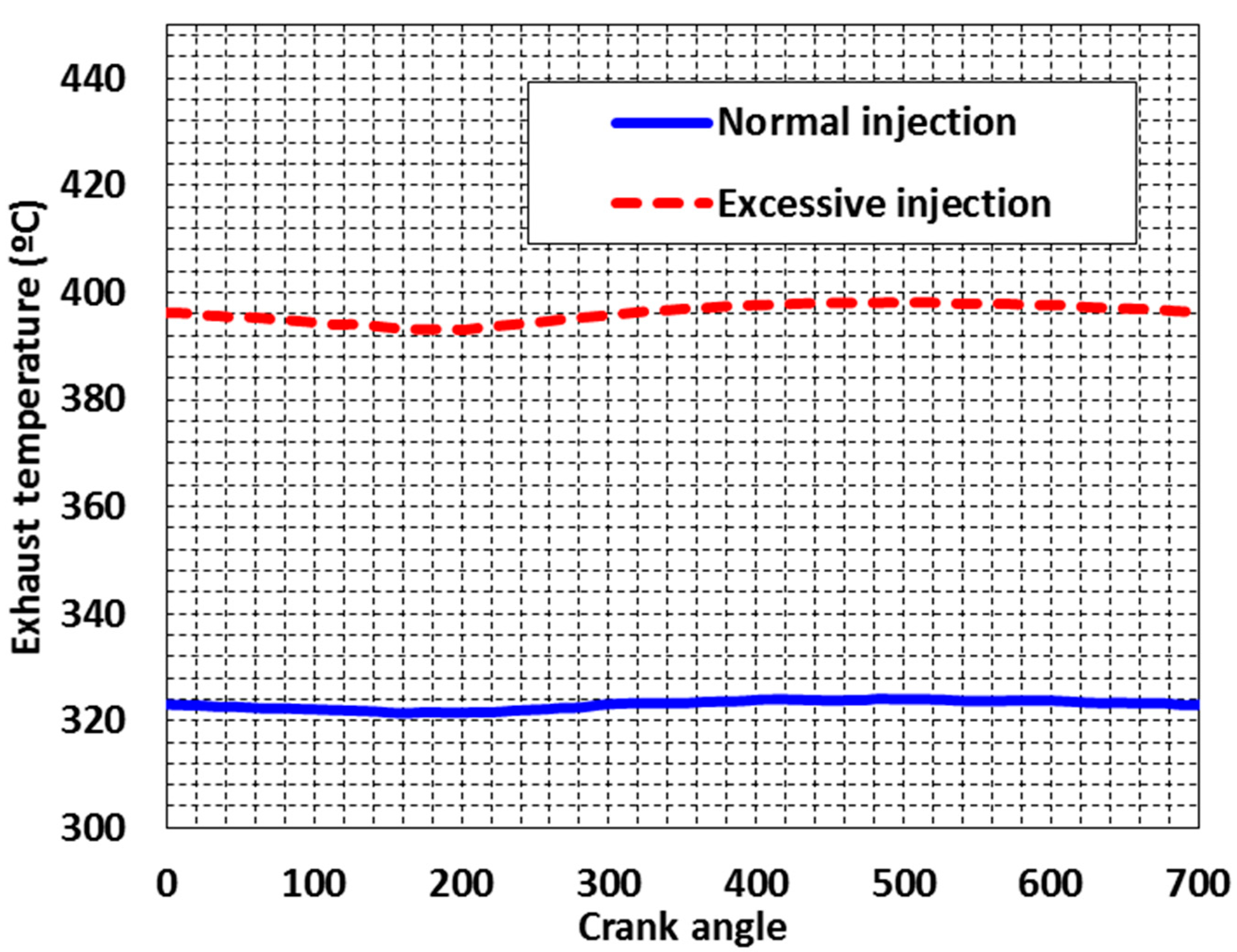
It has been discussed that the diesel engine thermal overload is most probably caused by sub-stoichiometric conditions in the combustion chamber. The sub-stoichiometric conditions can be achieved by either keeping the air flow rate constant which increasing the fuel flow rate or vice versa. During the testing, the air flow rate is kept constant, and the fuel injection amount is increase to reach the sub-stoichiometric condition. Results from the measurements taken on the selected engine at constant load and variable fuel delivery i.e., normal and excessive injection are shown in
Figure 6,
Figure 7 and
Figure 8. The exhaust valve open/close signals are set the same for both injection conditions, and the other operation parameters except for the fuel injection amount are remained unchanged during the testing.
The oxygen concentration in the exhaust gas leaving the cylinder is seen to fluctuate in a symmetrical signal with a constant deviation, which is demonstrated in
Figure 7. This is indicative of a reduction in the trapped air fuel ratio due to excessive fuel injection and the fluctuating signal is a consequence of pulse type turbocharging. If the oxygen concentration percentage drops below a particular value of 9%, then the test engine is of high risk to be operated at thermal overload condition, which will further induce to fatigue problem of the cylinder component. From the test results, it is found that the oxygen concentration for excessive injection is obvious lower that of the normal injection, which will of high possibility of thermal overload operation.
As demonstrated in
Figure 8, the use of a fast response thermocouple gives greater insight into the gas exchange process and assists in predicting the quality of combustion.
If the trapped air to fuel ratio is close to stoichiometric conditions, slow burning due to the non-availability of sufficient reactive species (local conditions) will result in a high exhaust gas temperature. However, the fast response thermocouple shows a marginal deviation in temperature over a cycle but its time response is not fast enough for medium speed engines. However, it does indicate that the deviation in exhaust temperature due to excessive injection can be detected with a standard thermocouple. A appropriately sized thermocouple can diagnose an engine thermal overload operating condition by observing a sharp rate of temperature rise at the start of the gas exchange process (blow down) indicating a much higher temperature competed to the mean exhaust temperature (shown in
Figure 4). Similarly, if there is loss of fresh air towards the end of the gas exchange process (scavenging), the thermocouple will come in contact with low temperature air which will be indicated by a sharp reduction in temperature. The amplitude of this cyclic variation in temperature may be regarded as an indicator of combustion air being lost at the end of scavenging, which results in a lower trapped air to fuel ratio.
5. Influence of Engine Thermal Overload
5.1. Test Engine Configuration
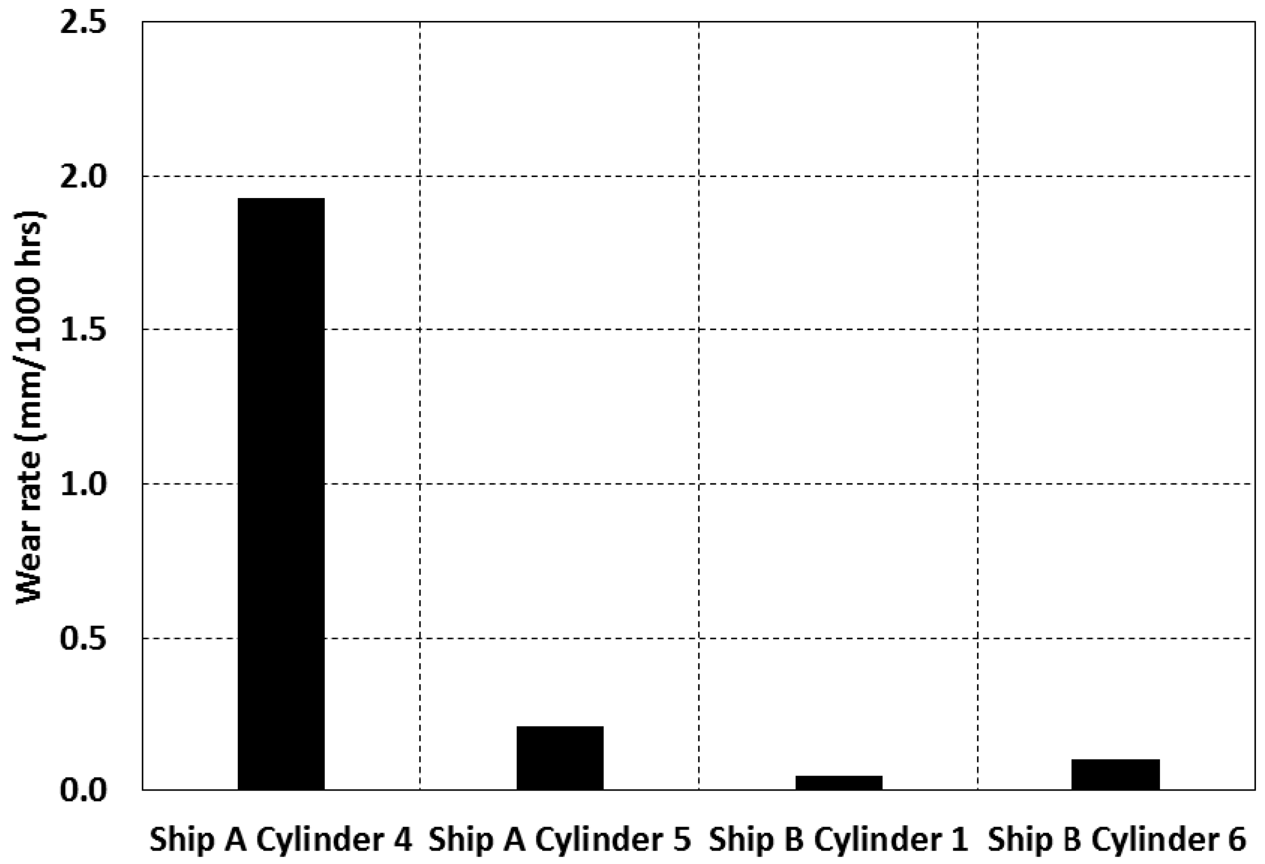
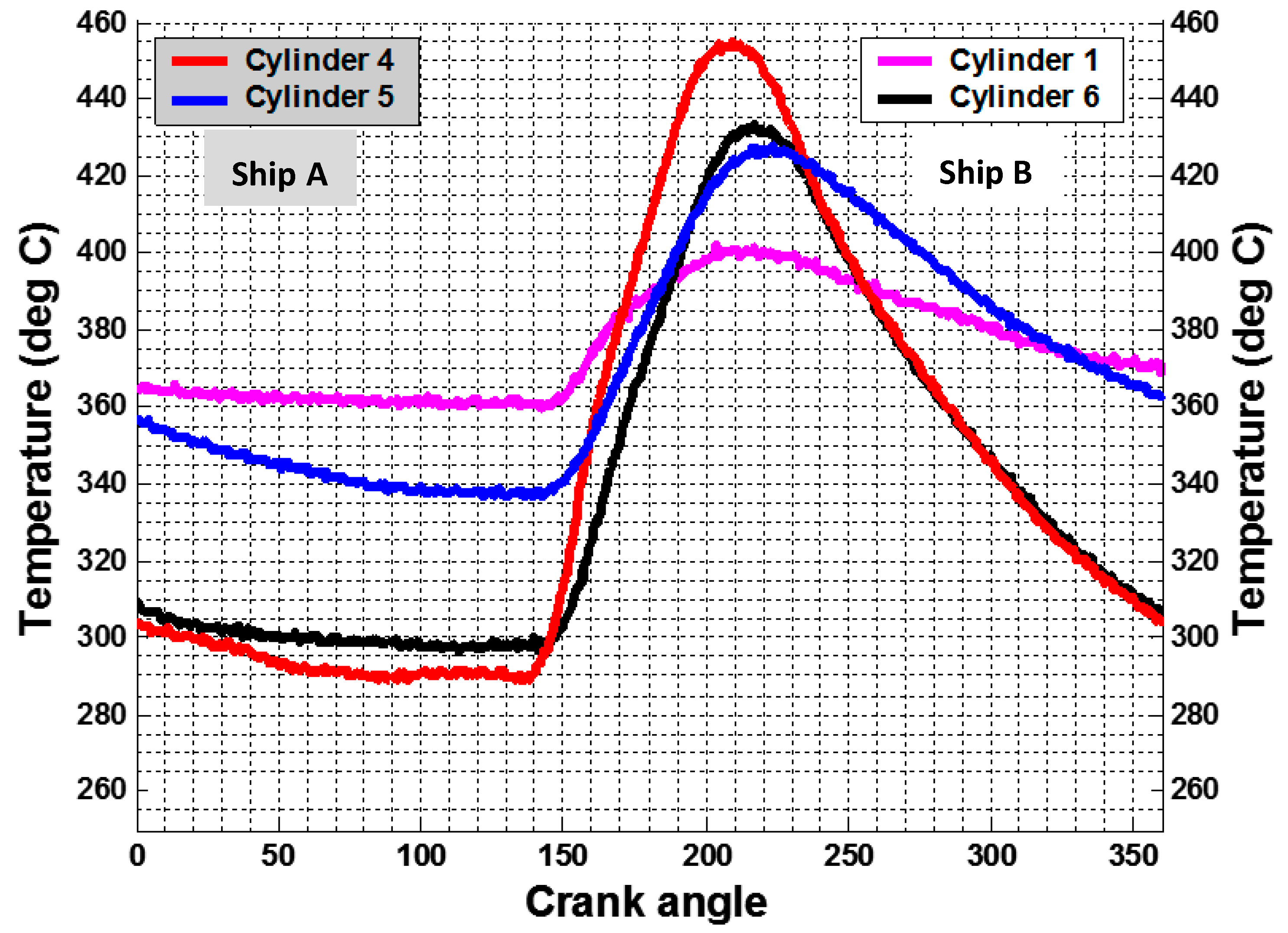
The tests were carried out on four cylinders of a Sulzer 7RTA84T engine having high piston crown burn rates. Power developed by the engine during the test was 80% of maximum continuous rating (27,160 kW). A large number of measurements were obtained and were found to be repeatable. As scavenging air flow through each cylinder is different the oxygen concentration values used to predict the trapped lambda are taken as the minimum value observed during the process. Tests were carried out at a later stage with an additional sensor, a fast response thermocouple, to investigate the correlation between gas temperature and oxygen in the exhaust gas. This was carried out on two ship engines, Ship A and B, which had the engine piston crown wear rates as shown below in
Figure 9. The wear rate measurement can be found in elsewhere [
24].
5.2. Test Results and Analysis
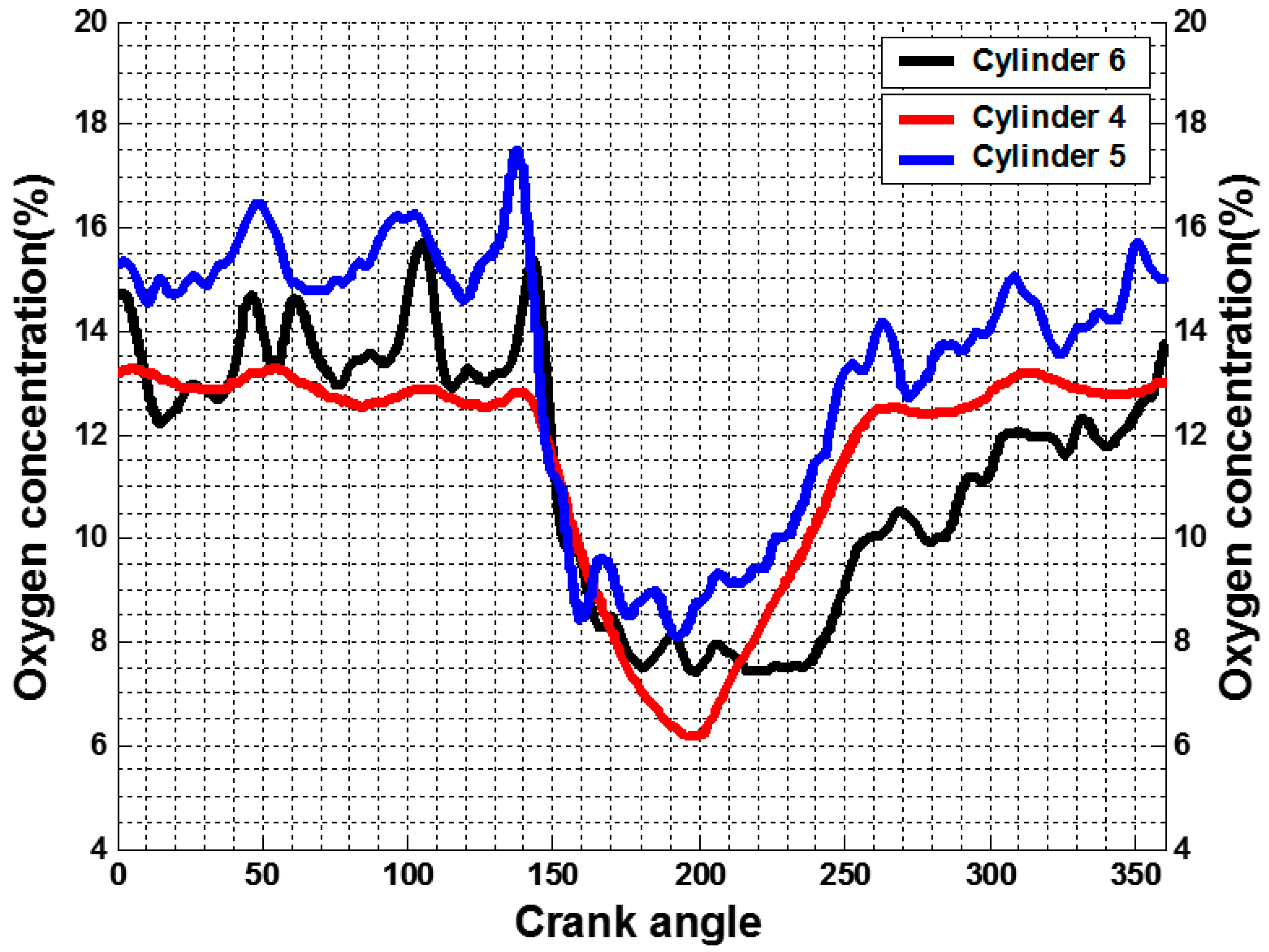
Figure 10 and
Figure 11 show that the correlation between exhaust temperature and oxygen concentration (except oxygen concentration of Cylinder 1 due to failed sensor), it can be established that a lower oxygen concentration in the blow down gas corresponds to a higher exhaust gas temperature. The lowest cyclic variation and lowest peak exhaust temperature suggests there is minimal or no combustion air loss at the end of the scavenging process, which results in a high trapped air to fuel ratio as in the case of Cylinder 1. The exhaust temperature of Cylinder 1 is lowest, and shows lowest piston crown wear rate.
From the data shown in
Figure 11, the oxygen concentration in Cylinder 4 is lowest (nearly 6%), and the exhaust gas temperature is highest. According to the analysis presented in
Section 3, when the detected oxygen concentration in the exhaust gas is lower than 9%, it will be of high possibility for the engine to be operated at thermal overload condition. As a result, the piston crown wear rate of Cylinder 4 is much higher than that of the other cylinder, due to the high rate of heat transfer from a voluminous flame.
6. Conclusions
In this research, the development of a diesel engine thermal overload monitoring system is presented with application and test results. The designed diesel engine thermal overload monitoring system mainly consists two set of sensors, i.e., a lambda sensor to measure the oxygen concentration and a fast response thermocouple to measure the temperature of the gas leaving the cylinder. From the calculation of oxygen concentration in the blow down gas, it is suggested that if the oxygen concentration percentage drops below a particular value of 9%, then the test engine is of high risk to be operated at thermal overload condition, which will further induce to fatigue problem of the cylinder component.
A medium speed Ruston diesel engine is instrumented to measure the required engine process parameters. Measurements are taken on the selected engine at constant load and variable fuel delivery i.e., normal and excessive injection. From the test results, it is found that the oxygen concentration for excessive injection is obvious lower that of the normal injection, which will of high possibility of thermal overload operation. With the application of the designed diesel engine thermal overload prediction system, it is able to help monitor the engine thermal conditions.
Tests were carried out on four cylinders of a Sulzer 7RTA84T engine having high piston crown burn rates to explore the influence of engine operating at thermal overload condition. It is established that a lower oxygen concentration in the blow down gas corresponds to a higher exhaust gas temperature. The oxygen concentration in Cylinder 4 is lowest (nearly 6%), and the exhaust gas temperature is highest. As a result, the piston crown wear rate of Cylinder 4 is much higher than that of the other cylinder, due to the high rate of heat transfer from a voluminous flame.
