
Screening of Available Tools for Dynamic Mooring Analysis of Wave Energy Converters


Department of Civil Engineering, Aalborg University, Thomas Manns Vej 23, Aalborg Ø 9220, Denmark
*
Author to whom correspondence should be addressed.
Energies 2017, 10(7), 853; https://doi.org/10.3390/en10070853
Submission received: 30 March 2017
/
Revised: 6 June 2017
/
Accepted: 23 June 2017
/
Published: 27 June 2017
Abstract
:The focus on alternative energy sources has increased significantly throughout the last few decades, leading to a considerable development in the wave energy sector. In spite of this, the sector cannot yet be considered commercialized, and many challenges still exist, in which mooring of floating wave energy converters is included. Different methods for assessment and design of mooring systems have been described by now, covering simple quasi-static analysis and more advanced and sophisticated dynamic analysis. Design standards for mooring systems already exist, and new ones are being developed specifically forwave energy converter moorings, which results in other requirements to the chosen tools, since these often have been aimed at other offshore sectors. The present analysis assesses a number of relevant commercial software packages for full dynamic mooring analysis in order to highlight the advantages and drawbacks. The focus of the assessment is to ensure that the software packages are capable of fulfilling the requirements of modeling, as defined in design standards and thereby ensuring that the analysis can be used to get a certified mooring system. Based on the initial assessment, the two software packages DeepC and OrcaFlex are found to best suit the requirements. They are therefore used in a case study in order to evaluate motion and mooring load response, and the results are compared in order to provide guidelines for which software package to choose. In the present study, the OrcaFlex code was found to satisfy all requirements.
1. Introduction
There is a variety of environmental loads on offshore structures, dominated by loads arising from current, wind and wave, which contribute to the motions of the structure. Therefore, these are vital for consideration when analyzing and designing floating structures, as it is necessary to control the motions in order to satisfy restrictions on the allowed excursion limit or to ensure the stability of the structure. A range of different solutions is available, but usually a mooring system is applied, which by definition is a system of lines connecting the floating structure to the seabed [1,2]. The offshore oil, gas and naval sectors have a long tradition of using moorings as a station-keeping system, and they have gained much experience and knowledge. Today, there is a wide range of design guidelines like DNV-OS-E301 [1], API-RP-2SK [2] or ISO 19901-7:2013 [3], and several authors like [4,5,6,7,8] have dealt with the topic.
The wave energy sector has many different concepts and devices for wave energy conversion; many of which are floating structures with the need for a mooring system [9]. Despite the large knowledge gathered from other offshore sectors, there is still a large amount of failures of wave energy converters (WECs) due to insufficient mooring, which causes significant damage to the devices and their development [4]. In addition, the need for optimizing WEC moorings is significantly greater compared to the mooring of other structures since some authors, as, e.g., [10], state that the cost of moorings for WECs takes up 18–30% of the total structure cost, while it is only 2% for an oil platform. This difference is partly due to the difference in size of the structures and partly the different requirements to and response of the WEC moorings. This puts new demands and focus on the choice of materials, design procedure and, in particular, analysis tools. Studies, as, e.g., [11], focus decidedly on moorings with synthetic ropes in order to optimize the cost and function of the devices, resulting in a great need for a proper tool for analysis. This can, e.g., be experimental work, but in order to include all effects, it is necessary to use sophisticated and expensive experiments. Often, numerical analysis is considered, which can cover both quasi-static and dynamic analysis. In [12], it was found that quasi-static analyses have a tendency to underestimate tensions in extreme waves, and therefore, this study considers only dynamic tools.
There is a great amount of commercial tools available, each of them with a set of specifications, capabilities and limitations, for the investigation of structure response and mooring loads. Many of the tools are mainly aimed at the traditional offshore sector and its requirements, resulting in uncertainty of the applicability to the wave energy sector. The purpose of this study is to identify the requirements of the software tools for WEC mooring analysis when the main concern is to have a tool that allows for obtaining a certified mooring system. In the final design, it will be necessary to validate the tool against experimental work or more sophisticated models following, e.g., the procedure in [13], but this is not the aim of this paper. Each design standard has requirements to the effects that must be included in the analysis, and the purpose of this paper is to identify these and evaluate whether the software packages provide the specifications to satisfy them. Additionally, the promising tools will be compared to each other in a case study in order to highlight potential differences in the capabilities.
The research only focuses on mooring of WECs that can be considered large relative to the incoming waves and only considers passive mooring systems; hence, systems where the mooring is not taking an active part in the energy absorption. The paper first introduces mooring modeling followed by an introduction to the main requirements defined in the design standards. There will be an introduction and comparison of a number of relevant commercially-available software packages, and the most promising tools are chosen for a simple WEC case study. In addition, there will be a comparison of the mooring line tensions and device motions in order to illustrate potential differences, together with advantages and drawbacks from each software package. This should allow for the selection of a dynamic tool, which can be validated in future work.
2. Dynamic Modeling of Floating WECs with Moorings
The combined current, wind and wave load exerted on the structure affect the dynamic behavior of the floating body. Using the Newton–Euler formulation, the equation of motion with reference to the center of gravity (CoG) is defined in Equations (1) and (2) [14]:
where is the resultant force vector, m is the structure mass, is the linear acceleration vector of the system, is the resultant moment vector, is the inertia matrix and and are respectively the angular acceleration and velocity of the structure. The resultant force and moment vectors are the combined forces and moments acting on the structure, hence consisting of a contribution from wind and current together with the total force and moment from wave exposure. The latter arises from the combination of hydrostatic and hydrodynamic pressure fields and results in a time-varying force. The resultant vectors are therefore defined as:
where , and , are respectively the wave excitation and wave radiation loads, which can be decomposed from the total wave load based on a linear assumption. and are the hydrostatic loads; and are the wind and current loads; and and are the mooring loads. The gyroscopic moment () from Equation (2) can initially be discarded in Equation (4) [14]. The excitation loads are defined as the loads exerted by the waves on the static structure, while the radiation loads arise from waves that are induced by the moving structure. The hydrostatic loads are the loads exerted by static pressure on the wetted body surface.
A Morison approach or boundary element method (BEM) is commonly used to solve the wave load contribution, but there are methods available that are more sophisticated such as computational fluid dynamics (CFD) or smoothed particle hydrodynamics (SPH).
When applying a mooring system to the floating WEC, the mooring loads are introduced into the equation of motion, as defined in Equations (3) and (4). For each time step, the equations of motion for the mooring lines are solved, and the mooring load is given as input to the equation of motion for the WEC. In general terms, the governing equation for mooring dynamics can be expressed as:
where is the cable mass, is the acceleration vector, is the force due to axial tension, is the force due to bending moment, the force due to torsional moment, the force due to hydrodynamic loading and represents the contact forces.
The solution to Equation (5) is commonly found using a finite element (FE) method where the mooring lines are discretized into several elements, and it is possible to advance in time and space by using a range of different methods with different orders of accuracy [15]. An approximation commonly used in mooring analysis tools is the lumped mass approach [16,17,18,19,20]. This can denote that the FE mass matrix is approximated with a lumped mass matrix where the properties of each element are redistributed to the elemental nodes, which results in a diagonal mass matrix and, therefore, eases the calculations and reduces the simulation time. Additionally, the lumped mass approach also implies a method where the lines are divided into a number of elements that are treated as point masses and springs.
Different software packages are able to solve the equations and simulate the mooring response, but how the mooring forces are implemented in the model and how the solution is computed vary for each package and to some extent affect the accuracy of the results.
3. Design Standards
There are several certification companies worldwide with the purpose of ensuring that the design of offshore structures is reliable and safe. By fulfilling the requirements from these companies, it is possible to certify the structure and allow it to be deployed at the desired location. These requirements are all specified in a number of design guidelines covering, e.g., analysis methodology, safety factors, material requirements, etc. Examples of design standards for floating structures are the DNV-OS-E301 [1], API-RP-2SK [2] and ISO-19901-7:2005 [3]. For WEC mooring design, the recent IEC-62600-10 [21] can be used. There is no significant difference between these design standards, and overall, they provide the same requirements. The main difference is on the safety factors, which this study will not treat any further. The following section briefly summarizes the requirements stated in the design guidelines on how to model the floating device, the induced loads on both body and mooring line and what type of analysis should be performed.
From a commercial point of view, the initial objective of the mooring design procedure is to be able to get a certified mooring system; hence, a certification company needs to certify the calculations and tools used. According to DNV-GL, a certain tool is not more likely to give a certified system than others are, and no requirements are stated on which software package should be used. However, it is expected for the software package to be verified against laboratory experiments on a case-to-case basis. For WECs, the ability to model the power take-off (PTO) is a crucial parameter.
3.1. Choice of Analysis
The oil and gas sector typically models mooring systems by a quasi-static approach and, therefore, states it as an appropriate methodology in some design standards. However, the reason for using a quasi-static approach is the large structures and corresponding low responses with insignificant velocities. For an oil and gas platform, large displacements can compromise the safety and functionality of the structure, and so, the system is designed to significantly reduce the response. In the WEC sector, the structures are typically of much smaller masses, and often, there is a tolerance of or even a desire for larger displacements. Therefore, a more distinct response with much higher velocity, but smaller loads, is often experienced, putting more demands on the type of analysis. According to both API-RP-2SK [2] and IEC-62600-10 [21], this requires a dynamic analysis, while DNV-OS-E301 [1] states that a quasi-static analysis is only appropriate in some conditions. However, for the type of mooring layout and site specification typically involving WECs, also DNV-OS-E301 [1] requires a dynamic analysis. For large WECs, a quasi-static analysis could be justified in a fatigue assessment in operational conditions, but as there must be a validation of the mooring in the ultimate limit state (ULS), the need for a dynamic analysis is still present. For a preliminary analysis, a quasi-static analysis might be more efficient due to the simplicity of the procedure, followed by dynamic analysis for the final design and validation. For both quasi-static and dynamic analysis, it is required that the weight and buoyancy of all components are included, together with the elasticity of the lines and interaction with the seabed. Often, the quasi-static approach neglects all dynamic effects from mass, damping and fluids and only considers horizontal displacements, while the dynamic analysis solves the equation of motion for all degrees of freedom and includes all dynamic effects [2].
In a mooring system, significant non-linearities are present, which the software package must model appropriately. Non-linearities cover, e.g., non-linear stretching of lines, changes in geometry, fluid and bottom effects. When solving the equations of motion, it is possible to use either a frequency or time domain approach. In the frequency domain, a set of linear equations of motion treats the motions and calculates and combines statistical peak values for different motion contributions. Since the equations of motion are linear, analyzing in the frequency domain requires linearization of all non-linearities, thereby introducing inaccuracy between nature and the model. This linearization is unnecessary in the time domain where direct numerical integration will solve the system. A time domain analysis, therefore, also provides time histories of, e.g., WEC displacements and line tensions. It should be noted that this could also be found from the frequency domain parameters as these contain information on phase and amplitude. When having the time series, it is then possible to use statistical analysis to find extreme values. Using, e.g., a finite element method to model the mooring lines in the time domain gives the opportunity to include all of the dynamic effects from mass, damping and fluid loading. The time domain analysis should be modeled long enough to ensure statistical satisfaction, and often a total number of 1000 waves or three hours of simulation is recommended [1]. When solving the equation of motions, two different methods can be used, namely the coupled or uncoupled method [1]. In the uncoupled method, the motions are initially solved either by neglecting the influence of the mooring lines or by including them as a constant stiffness. The fairlead motion of the WEC is then fed into a cable solver, and tensions in the mooring lines are solved. In the coupled method, the complete system of equations for both WECs and lines are solved simultaneously. In order to fully model the influence of mooring lines on the WEC motions and the full non-linear behavior of the mooring system, the design standards state that a coupled analysis should be used in almost all cases. Similarly, this requires the use of a time domain simulation with all non-linearities and dynamic effects.
3.2. Environmental Loads
The ability to model the environment and induced loads is a vital capability of the software. The design standards have specific requirements on how to model and include loads, listed below.
3.2.1. Current
Current can be treated as a steady force calculated by a drag force formulation as:
where F is the current force, is the fluid density, is the drag force coefficient, A is the cross-sectional area and v is the fluid velocity. When calculating the loads on the WEC and the lines, the current must be modeled with a vertical variation according to profiles specified in the design standards.
3.2.2. Wind
The wind load modeling must consist of a steady mean component and a time-varying gust effect. The mean component should be described with a vertical wind profile and time-variation described by relevant wind spectra. A drag load formulation will calculate the load similar to the current load.
3.2.3. Wave
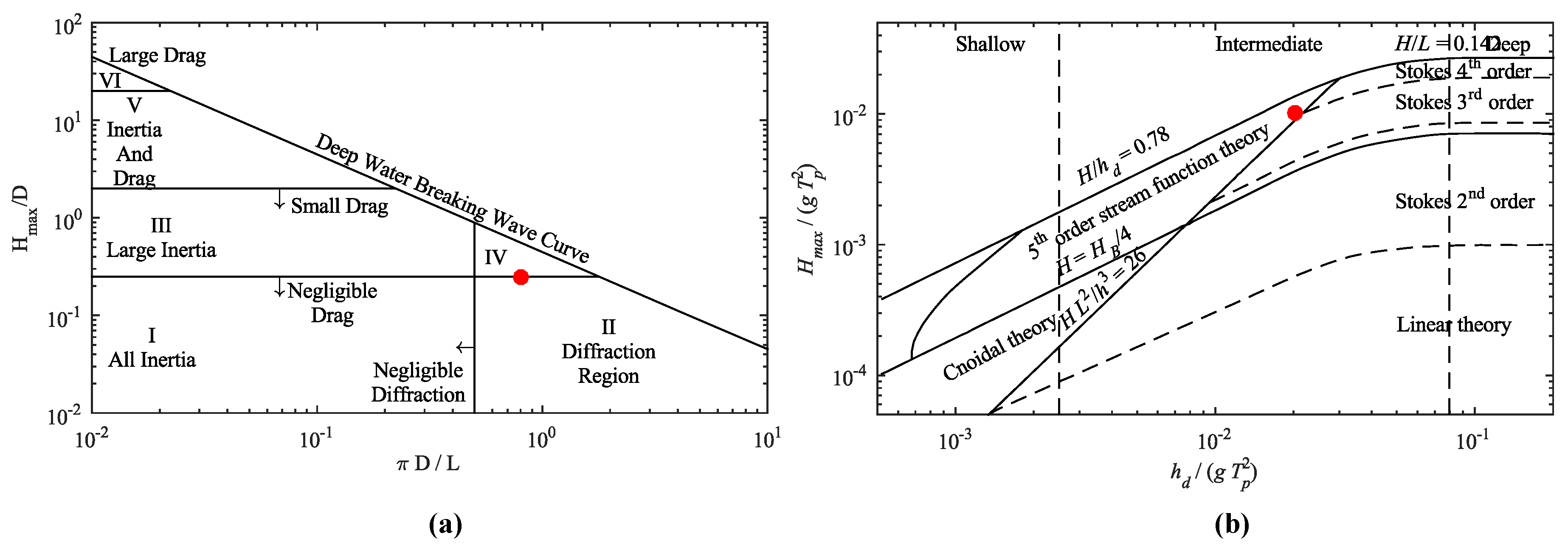
The wave load can be decomposed with good accuracy into a few components, i.e., a wave frequency (WF) load, oscillating at the frequency of the incoming waves, a second order low frequency (LF) load and a second order mean drift load. The description of the response must include both the WF, LF and mean drift. For small structures with a diameter less than a fifth of the wavelength, radiation and diffraction loading are negligible, and a Morison approach can be used, cf. [1] and Figure 1a. For larger structures, radiation and diffraction dominate the wave loads, and BEM codes, as e.g., NEMOH [22] or WAMIT [23], can be used.
4. Dynamic Mooring Analysis Tools
There is a large number of software packages for mooring analysis of floating structures, covering, e.g., quasi-static tools for design of ports and offshore oil and gas structures and likewise many tools for dynamic analysis. For the WECs, only dynamic tools are considered. A preliminary analysis provided the list of relevant software candidates defined in Table 1. The versions of the software packages correspond to the version available at the time of the screening.
There are many other dynamic tools, e.g., the in-house code CASH by GVA, ZenMoor by Zentech Inc., WAMSIM by DHI Group and the MooDy code by Chalmers University of Technology [31]. A widely-used software package is the Ariana-3Dynamics by Bureau Veritas, which uses a cable dynamic module, developed by Wood Group Kenny and which is based on the Flexcom software. From these additional codes, this paper will only consider MooDy further. The following sections will include a short description of each software package, followed by a full comparison of specifications.
Aqwa [20] is a software package developed by ANSYS Inc. used to investigate the influence from environmental loads on fixed and floating offshore structures. The software benefits from having a hydrodynamic BEM code implemented and is capable of solving both first and second order wave effects in both the frequency and time domain. Both wind and current are modeled according to the design standards. The dynamic mooring lines are modeled using a discrete lumped mass approach where each line is divided into a number of segments where the mass is concentrated into a corresponding node. The code uses a two-stage predictor corrector method for advancing in time.
Flexcom [26], developed by MCS Kenny, is a structural analysis tool aimed at the offshore sector. The software is capable of including all environmental loads specified by the design standards and takes the hydrodynamic coefficients from external diffraction-radiation analysis software as input, including response amplitude operators (RAOs) and quadratic transfer functions (QTFs) for the calculation of respectively first and second order wave effects. The software models the mooring lines using a finite element solution based on a hybrid finite element beam model where the axial displacement and rotation are given by a linear basis function, a cubic basis function for the transverse displacement and a constant basis function for the axial force and torque moment. Time stepping is done by a second order implicit generalized- method with the option of variable time steps based on the current period parameter.
MOSES [27] is a software package for modeling, designing and planning for offshore floating structures, including the calculation of the hydrodynamic coefficients. The environmental loadings are well described, and mooring lines are solved for tension, bending and torsion. The beam equations are solved by linear finite elements. An implicit Newmark -scheme, typically of second order, is used for time stepping.
OrcaFlex [19] is a marine dynamic software package developed by Orcina Ltd. allowing full analysis in the time and frequency domain. The software is capable of calculating wave loads from a Morison approach, and for radiation-diffraction loading, input is needed in terms of RAOs and QTFs. Wind and current loading are both considered according to design standards. OrcaFlex solves both tension, bending and torsion using a discrete lumped mass approach with a time-stepping scheme that can be either explicit by the first order forward Euler method or implicit by the second order generalized -method.
ProteusDS [28], developed by Dynamic System Analysis Ltd., is a software for full dynamic analysis of offshore structures in the time domain. The software uses a Morison approach for the calculation of wave loads or additionally user-specified hydrodynamic coefficients. The present version of ProteusDS does not calculate the second order wave effects, and the wave drift and LF motion are not computed. A part of the contribution to the wave drift is by now included, and the implementation of QTFs is expected in future releases. The software does contain advanced mechanism modeling capabilities suitable for predicting WEC performance, important for characterizing the PTO of WECs. The mooring lines are solved for both tension, bending and torsion, using a cubic spline finite element method, meaning that the solution inside an element is given by a fourth order polynomial with a lumped mass matrix in order to speed up calculations. A fourth order Runge–Kutta scheme with an adaptive time step is used for advancing in time. The numerical error introduced by the time integrator is maintained below a defined level by adjusting the time step.
SeaFEM [29] is a software package developed by Compass with the aim of seakeeping and maneuvering simulation with the implementation of wave, wind and current effects on the structure. The software can perform both frequency and time domain analysis, and SeaFEM has the advantage of using a 3D FE model for solving the total fluid domain and its interaction with the floating structure in each time step. The software has not directly implemented wind load, which needs to be defined as a user-specified load. Currents can be included, but only with a constant velocity over the water depth. The dynamic mooring equations are solved by linear bar elements, and the solution is updated in time using a second order Newmark scheme.
DeepC [30] is a software package distributed by DNV-GL consisting of two pieces of software Riflex and Simo and combined with the HydroD package for hydrodynamic analysis. In combination, the DeepC software is capable of analyzing the environmental impact on floating structures and mooring lines accounting for first and second order wave effects, current and wind. The lines are solved for tension, bending and torsion and come with a linear bar element and with hybrid bar elements using a combination of linear basis functions and cubic basis functions. The mass matrix can be lumped for computations that are more efficient. The time integration uses an implicit Newmark -scheme, typically second order, and solved with a Newton–Raphson method.
MooDy [31] differs from the other software by being an in-house code of Chalmers University and not being a complete software package. The code is merely a dynamic cable solver and needs to be combined with other codes that are capable of solving the interaction between WEC and cables. A feature of MooDy is the use of the spectral/hp discontinuous Galerkin method, i.e., an arbitrary order (set by user) finite element method. The code uses explicit time stepping, including the third order Runge–Kutta scheme and a second order leap-frog scheme. Since MooDy is not a commercial software, it is only included in the following comparison in order to illustrate the potential of cable solvers and will not be considered for the case study.
4.1. Comparison of Software Packages
Largely, the software packages provide the same specifications, and since most codes are validated, it is expected that the obtained results will be in the same range. Still, some of the software packages excel when comparing all specifications. For comparison, the requirements from the design standards are considered. According to these, moorings need to be analyzed in the time domain using a fully-coupled analysis, and in addition, the software needs to be able to model the wind and current loads as profiled in the vertical direction. Modeling of the time-varying nature of the wind is a requirement, while it is only necessary to model a steady current velocity. Table 2 compares the software according to these requirements.
As seen from Table 2, all software fulfils the requirements, though SeaFEM is only capable of modeling a uniform current and wind.
When considering shallow water depths, in which many WECs are planned for deployment, the need for high order wave theory is present. All software needs to be able to implement diffraction/radiation loads in the case of large structures either by performing the analysis itself or using input variables. Table 3 specifies the capabilities for each software package concerning the wave influence.
Some variation of the implemented wave theories is present, but in general, high order Stokes theory is available. All software packages are capable of simulating irregular sea states, and diffraction/radiation or Morison load can either be computed by the software packages or input by the user. Most software includes second order wave effects, except from ProteusDS, which at present only includes some contribution to the wave drift. SeaFEM has implemented a second order solver, but this cannot be enabled together with current loads in the available version.
In mooring analysis, the dynamic cable solver is obviously one of the main features. Table 4 defines the specification of each software package, now also considering the MooDy code. The comparison considers the included contribution to the calculated mooring loads, together with the order of the schemes used for advancing in time and space. The use of a lumped mass matrix in the software is stated, but the table does not differ between the two meanings of the approach as described previously. Finally, the table lists the capability to model non-linear axial mooring line stiffness, which is an important feature when modeling, e.g., synthetic ropes.
The capabilities are identical in most software packages, while codes such as MooDy and ProteusDS are highlighted due to the high spatial and temporal order. However, it is still expected that similar results will be achieved in all software, despite the order of the code.
Table 2, Table 3 and Table 4 are suitable for choosing an optimal tool for dynamic mooring design and ensuring that the design standards can be satisfied. Many of the software packages have apparent similar specifications, but OrcaFlex, DeepC, ProteusDS and SeaFEM are considered strong candidates. As seen in Table 4, the dynamic cable solver in ProteusDS is most advanced, but at present, the main drawback of this software is the lack of capability to calculate the second order wave effect. Considering WECs in shallow water with compliant mooring, the drift effect is of paramount importance.
The SeaFEM software mainly advances because of its hydrodynamic solver, based on an FE formulation of the entire fluid domain. The software is, therefore, not dependent on frequency domain results (RAOs and QTFs) for calculation of motions and will provide the best description of non-linear irregular waves. Similar, the code has the potential to provide a better description of the current effect as it is calculated from the pressure on the body and not from a drag coefficient. However, for large structures with a high Reynolds number and turbulent flow, SeaFEM does not model this properly since the solver assumes steady streamlines. At present, the solver is also not capable of solving second order effects in combination with current, and computing just the second order wave effects puts such high demands on the mooring solver that the solutions often diverge. Another important factor to consider if using SeaFEM is the much higher computational time, compared to the other software packages. It should be noted that this is caused by the fact that SeaFEM solves the entire domain in each time step and, therefore, gives a better description paid by the longer simulation time.
Considering Table 2, Table 3 and Table 4, DeepC and OrcaFlex appear to have similar specifications. The DeepC solver might be more advanced than OrcaFlex as it can solve the mass continuously over the mooring line, while OrcaFlex uses the lumped mass approach and models the lines as point masses and springs. However, studies have indicated that an acceptable level of accuracy can also be achieved with this method. Both DeepC and OrcaFlex have been validated in several studies, and OrcaFlex is widely used for commercial purpose in different offshore sectors, while DeepC is developed and distributed by the certification company DNV-GL. A drawback of the DeepC package is the need for calculating static position in additional software, and for long simulations like, e.g., three hours, the software introduces a limitation of the number of calculations, which results in higher time steps and therefore possibly unstable solutions.
This paper will compare the performances of the OrcaFlex and DeepC packages, as these seem to fulfil the requirements in the design standards. No validation of the software packages will be conducted in this paper, as they are both commercial software packages, which have been validated for other applications as stated by [32,33]. The purpose of the following section is to investigate the potential difference between the results from each software package and allow for selection of the final tool. In a later publication, the selected software package will be validated for the present application.
5. Case Description
The considered case resembles a range of large floating WECs from the Danish wave energy sector. Examples of this kind of structure could be the Floating Power Plant [34], LEANCON Wave Energy [35], KNSwing and Wave Dragon [36] (cf. Figure 2) with widths in the range of 28–152 m and lengths of 60–240 m.
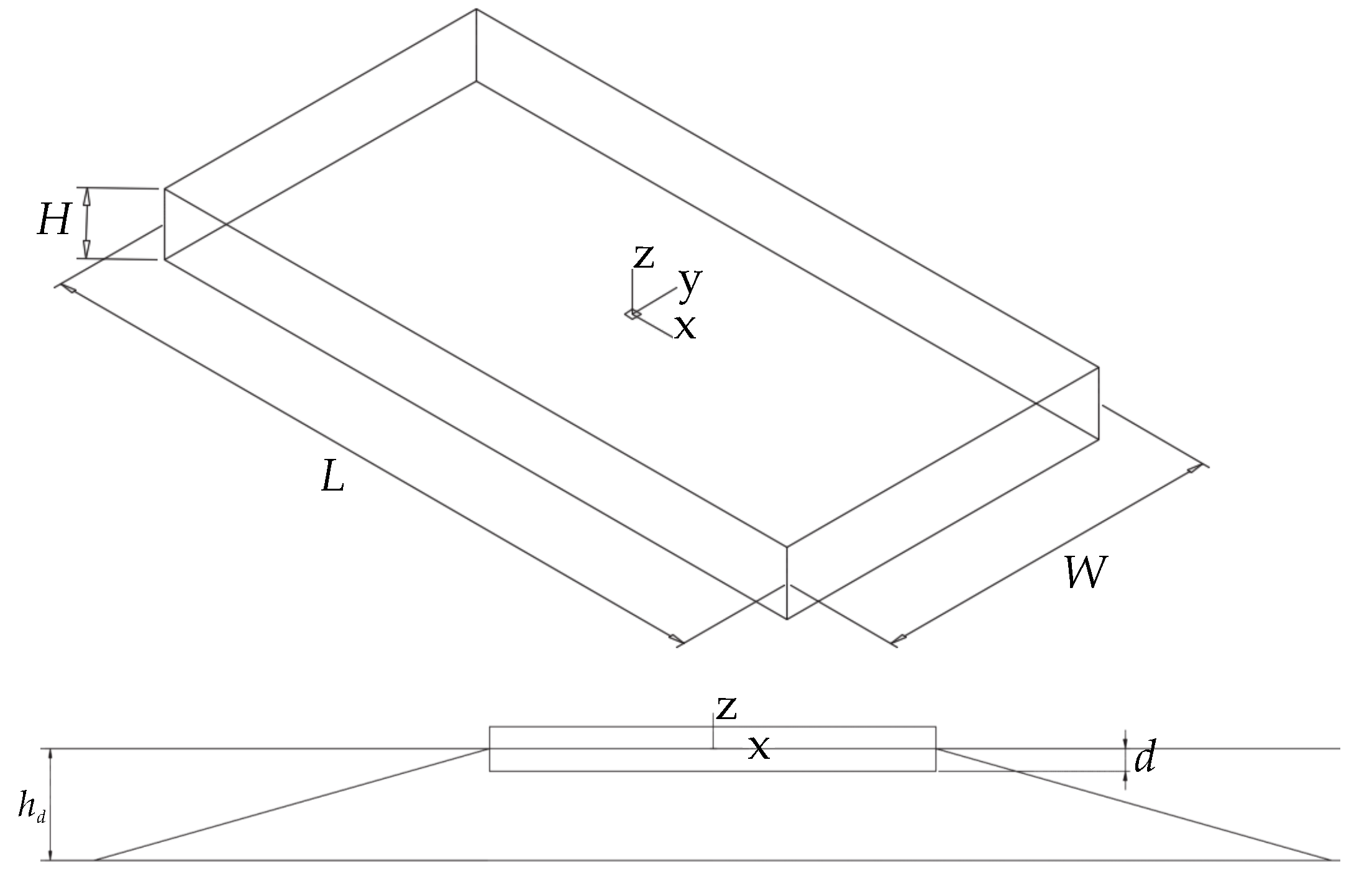
The case will analyze the mooring in the ULS and consider extreme events comparable to sites where these types of WECs are expected to be deployed. Because of this, it is assumed that the WEC is in storm protection, and the PTO is not included in the calculations. For simplicity, the structure is assumed to have the shape of a barge with dimensions in the range of the mentioned WECs. The geometry of the device is illustrated in Figure 3 and the dimensions specified in Table 5.
The device is spread-moored with four mooring lines consisting of synthetic rope, with specifications as listed in Table 6.
The characteristics of the barge, in terms of moment of inertia I and hydrostatic stiffness , are calculated either by the software packages or manuallyand is listed in Table 7. The characteristics from each method have been compared and show identical results.
A site suitable for the type of devices in Figure 2 is considered and is characterized by the parameters defined in Table 8. The sea state is described by a JONSWAP spectrum, and for simplicity, a current profile is assumed with no variation in velocity over the depth. In these simple simulations, any wind force is not included.
Figure 1a shows that the wave loads on the WEC are dominated by the radiation and diffraction components. Considering also Figure 1b, it is seen that the sea state can be considered to be in intermediate water depths with non-linear waves. It should be noted that the calculation of hydrodynamic coefficients is based on linear theory and that Figure 1a is also for deep water conditions.
The HydroD module of the DeepC package is capable of solving the hydrodynamic coefficients for added mass, radiation damping and the first and second order wave excitation force. OrcaFlex needs these coefficients as input from additional software. This case uses the open source BEM code NEMOH [22]. When comparing the results found from DeepC and NEMOH, there is good agreement between the results. Figure 4 presents the calculated motion RAOs from NEMOH and DeepC.
6. Mooring Analysis
In order to illustrate the performance and usability of the software, a simulation with the described sea state and model is performed for a time duration of 15,000 s. The following sections illustrate the differences between the results obtained from each software package.
6.1. Static Configuration
The static configuration of the system is obtained from equilibrium between weight, buoyancy and pretension of WEC and mooring lines, without the presence of any contribution from waves, wind and current. Table 9 shows the comparison between static line tensions in the two codes. Almost identical results are obtained, but it needs to be noted that DeepC is limited in the calculation of the static configuration as it assumes that the buoyancy of the WEC is equal to its mass. When applying mooring lines, the additional mass and potential pretension are not accounted for, and the WEC is pulled down. Therefore, it is necessary to calculate the static configuration beforehand and to apply a compensation force. For the present case, this force was calculated in a self-made script. For a simple configuration, this is relatively easy, but for more advanced systems, it might slow down and complicate the analysis.
6.2. Dynamic Response Analysis
Based on the hydrodynamic properties of the WEC, the motion response of the device and the corresponding tensions in the lines are simulated. Figure 5 presents the motion RAOs calculated from the output response from both software packages. The results are bandpass filtered with lower and upper limits of respectively 1/3 and 3 (where is the peak frequency) due to insignificant wave energy below and above these values, resulting in high disturbance on the calculated RAOs. The motion amplitudes are oscillations around the mean value of respectively 10.7 m and 11.2 m for OrcaFlex and DeepC for the surge degree of freedom (DOF).
Figure 5 illustrates how the mooring system reduces the motion amplitudes in both surge and heave. Due to the band pass filtering, it is not possible to detect a resonance frequency for these two DOFs, because they are both lower than 1/3 . The analytical natural frequency for surge, for instance, was found to be 0.008 Hz and hence, significantly below the wave frequencies. This resembles a realistic case, as floating structures ideally are designed with natural frequencies outside the wave frequencies of extreme events.
The pitch natural frequency is approximately 0.1 Hz and is well defined in Figure 5. The presence of the mooring system increases the pitch motion amplitude while the resonance frequency is slightly increased. The results obtained from OrcaFlex and DeepC show good agreement and show the highest deviation in the pitch DOF where the motions calculated by DeepC are higher than those calculated by OrcaFlex, and the resonance frequency is offset.
Figure 6 reports the tension spectral density in the line on the seaward side of the WEC. The amplitudes are around the mean tension of 629.8 kN for OrcaFlex and 614.9 kN for DeepC.
Similar to motion results, the calculated tensions in the lines are in the same range, and without any difference in the spectral shape. The peak value amplitudes have a slightly higher value in the DeepC code, but the difference approaches zero for shorter frequencies. When comparing the time series, a maximum tension of 2100.7 kN is obtained in OrcaFlex, while 1794.5 kN is obtained in DeepC. The load is 1616.3 kN in OrcaFlex, while 1711.2 kN in DeepC, where corresponds to the average of the 1/250 of the maximum peaks. It should be noted that the wave time series used in the two simulations are not identical, but only following the JONSWAP spectrum with identical frequency domain parameters. To obtain more reliable results for comparison, more time series should be computed and statistical information identified.
6.3. Response to Harmonic Waves
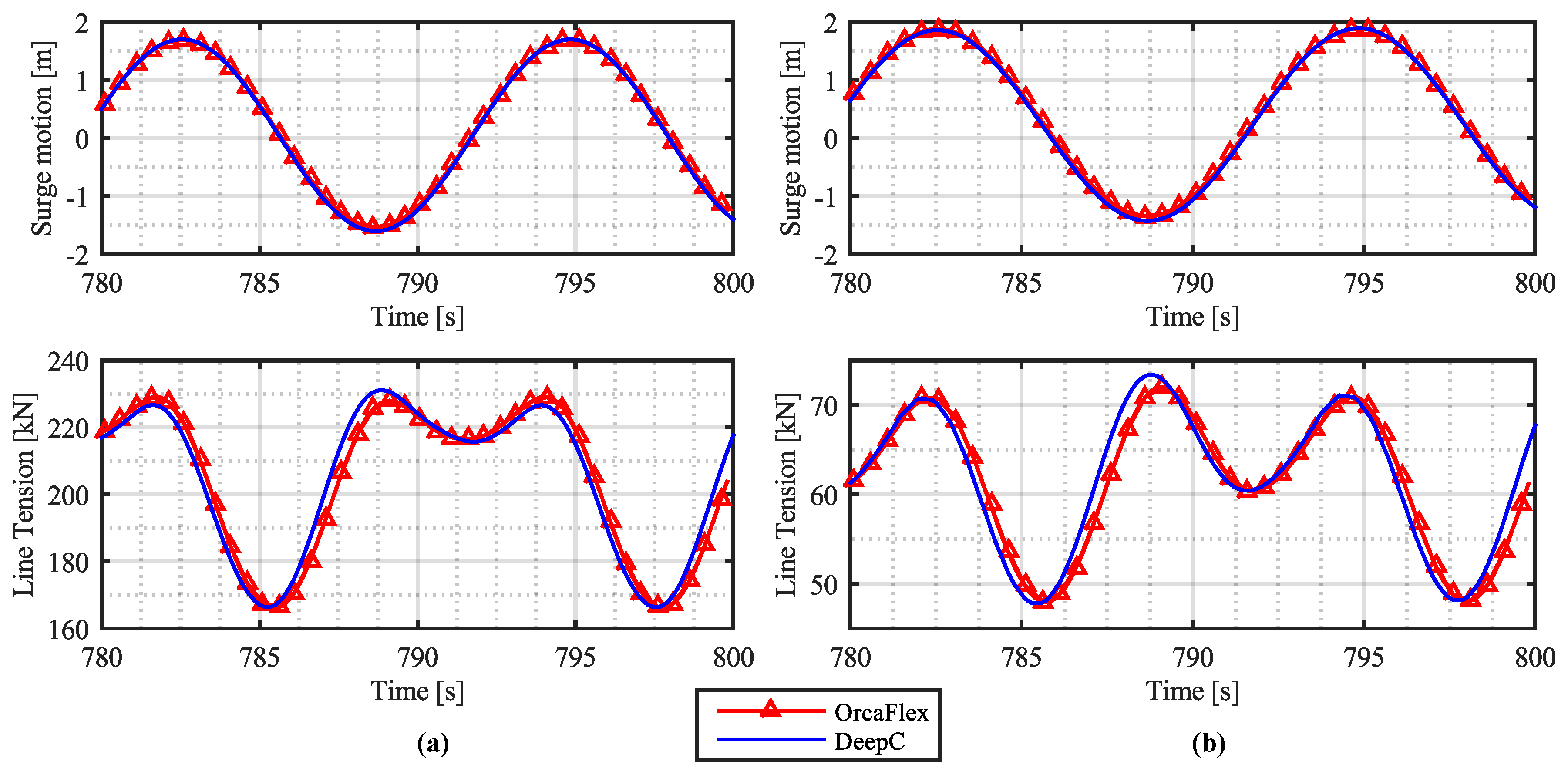
In order to provide a direct comparison of a time series computed by DeepC and OrcaFlex, a simulation of the WEC exposed to harmonic waves is used. The harmonic wave series has a wave height and period similar to the significant wave height and peak period from the previous case.
Figure 7 presents a comparison between OrcaFlex and DeepC time series for surge and line tension where no wave drift and current is present. The two software packages provide approximately similar results and seem to have identical values at the wave crests and small variations in the wave through. As previously stated, it is a vital parameter to be able to model non-linear material properties, as synthetic ropes seems to become subjected to more research. Figure 7 additionally illustrates the ability of the software packages to model the non-linear axial stiffness of a nylon line. If the stiffness curve for this material were linearized, it would result in a similar stiffness as used previously in the case. There is an agreement between the two software packages, together with a reduction in the mooring line tension when using non-linear axial stiffness.
Both OrcaFlex and DeepC model the mean equilibrium position as the combination of two excursion components; an excursion arising from the presence of current and an excursion from wave drift. The load on the device from the current is in both software packages expected to be similar as they are based on a drag formulation based on input variables like the drag coefficient, current velocity and cross-sectional area. The induced excursion and corresponding line tensions arising from current only are, therefore, also found to be similar, cf. Table 10, which presents the induced horizontal surge motion and line tensions.
The mean wave drift is calculated based on the input horizontal wave drift coefficients. These are the direct out-put of the HydroD analysis and, therefore, used in the DeepC package, or they can, e.g., be calculated from the output of Nemoh. The test case for the two software packages uses similar drift coefficients. However, as seen in Table 10, the difference between the results of OrcaFlex and DeepC is more prominent than for the current only. When considering the case where both wave drift and current are present, again the difference is present. Despite the fact that OrcaFlex provides the highest surge motion and line tension when considering the separate effects of the current and wave drift, DeepC provides the largest values when combining the contributions. An explanation could be how the software packages calculate the wave-current interaction. From Table 10, the importance of being able to include second order wave drift is clear. By using a software package only capable of including the current load and no mean wave drift, only approximately 60% of the actual line tension is taken into account.
7. Discussion
The comparison of software packages for mooring analysis illustrates that most of the existing software packages have the potential of fulfilling requirements defined in the design standards and thereby allowing for a certified mooring system. Some of the software seems more sophisticated than others, and a software package such as, e.g., ProteusDS excels with the dynamic cable solver while SeaFEM excels with its hydrodynamic solver. However, not fully including second order wave effects limits both of these, which is why the two software packages OrcaFlex and DeepC were chosen for testing on a simplified WEC. These two software packages provide an overall solution for mooring analysis and have the potential of including all needed effects. By comparing the results from the two cases, there was good agreement between the software. In later work, it is paramount to validate the tools against experimental data or a CFD/SPH model before they can finally be used for a certified mooring analysis. This study has now presented that the two tools provide the necessary capabilities and produces similar results. For further comparison, however, it would be advantageous to perform more than one time series simulation, which will allow for statistical comparison between the results.
The two software packages both advance by having a simple user interface and high usability when defining the model, while OrcaFlex eases the process of defining the simulation procedure, integration parameters and provides better support in defining reasonable parameters. Computational time appears to be relatively similar for the two cases, but since no convergence analysis was performed on the discretization of the mooring lines, it is not possible to know if any of the software packages can be optimized to simulate faster than the other.
8. Conclusions
The present study presents an initial study on the applicability of commercial analysis tools for WEC mooring designs. The requirements defined in the design standards were briefly described, which the tools need to be able to model in order to ensure the certification of the final mooring design. The main requirements consider modeling of environmental loads, non-linearities and dynamic effects. The study presents a list of potential software and lists their available capabilities at the time of the study. Most software packages are under a constant development and it is, therefore, recommended to investigate them before future analysis by e.g., following the same procedure as in this paper. Most software provides almost identical capabilities, while some software packages have more sophisticated methods available. From the list, the study highlights the two packages DeepC and OrcaFlex as potential software solutions in mooring analysis and simulates a test case resembling a large floating WEC. The results showed good agreement between the two software packages when considering both motion and tension responses. A comparison of the abilities of the software packages to model current and wave drift showed little variation, but still provided results in the same range. Finally, a test of the ability to include non-linear axial mooring line stiffness again showed good agreement between the two software packages and resulted in a reduction in loads, caused by the more compliant line.
For further comparison between the two cases, it would be reasonable to include more time series and statistical analysis or additionally to simulate an identical time series. Validation against experimental results or CFD simulations would similarly provide a better indication of the capabilities of the software packages and is a necessary step before the final design of mooring systems.
Based on the results from the test cases, the conclusion is that the two software packages both have the potential for use in WEC mooring analysis. DeepC has the drawback that it requires use of additional software to calculate static position and inclusion of a compensation force. In addition, the evaluation of the software package concluded it to be less user-friendly than OrcaFlex and to have a limitation in solving the number of potential problems in each simulation. This leads to higher time steps, which potentially makes the mooring solver unstable. Since relatively long time series often are necessary for statistical purposes, this might cause problems in some cases.
It is found from the analysis that similar results are obtained from both software packages. DeepC has some drawbacks, while OrcaFlex is widely used in the commercial sector and fulfills all of requirements that have been listed. Therefore, there are no arguments for not using OrcaFlex in the analysis of mooring systems for large WECs.
Acknowledgments
This study was funded by the Energy Technology Development and Demonstration Program (EUDP) through the project “Mooring Solutions for Large Wave Energy Converters” (Grant number 64014-0139). The authors wish to acknowledge DNV-GL, Compass, Dynamic System Analysis Ltd. and Orcina Ltd., for providing information and access to their software packages together with the review of this paper. The authors further wish to acknowledge Claes Eskilsson from Chalmers University of Technology for providing input to this paper.
Author Contributions
Jonas Bjerg Thomsen defined the overall outline of the study and the relevant parameters to investigate, with input from Francesco Ferri and Jens Peter Kofoed. Jonas Bjerg Thomsen collected data and information and performed the numerical analysis, analyzed the data and drafted the paper. Jonas Bjerg Thomsen, Francesco Ferri and Jens Peter Kofoed finalized the paper.
Conflicts of Interest
The authors declare no conflict of interest.
References
- Det Norske Veritas (DNV). Offshore Standard DNV-OS-E301 Position Mooring; Det Norske Veritas: Høvik, Norway, 2010. [Google Scholar]
- American Petroleum Institute (API). Design and Station Keeping Systems for Floating Structures; American Petroleum Institute (API-RP-2SK): Washington, DC, USA, 2015. [Google Scholar]
- International Organization for Standardization (ISO). ISO 19901-7:2005 Station Keeping Systems for Floating Offshore Structures and Mobile Offshore Units; International Organization for Standardization: Geneva, Switzerland, 2005. [Google Scholar]
- Martinelli, L.; Ruol, P.; Cortellazzo, G. On mooring desgin of wave energy converters: The seabreath application. In Proceedings of the 33th Conference on Coastal Engineering, Santander, Spain, 1–6 July 2012. [Google Scholar]
- Johanning, L.; Smith, G.H.; Wolfram, J. Mooring design approach for wave energy converters. Proc. Inst. Mechan. Eng. Part M J. Eng. Marit. Environ. 2006, 220, 159–174. [Google Scholar] [CrossRef]
- Harris, R.E.; Johanning, L.; Wolfram, J. Mooring systems for wave energy converters: A review of design issues and choices. In Proceedings of the 3th International Conference on Marine Renewable Energy, Blyth, UK, 6–9 July 2004. [Google Scholar]
- Paredes, G.M.; Bergdahl, L.; Palm, J.; Eskilsson, C.; Pinto, F.T. Station keeping design for floating wave energy devices compared to floating offshore oil and gas platforms. In Proceedings of the 10th European Wave and Tidal Energy Conference, Aalborg, Denmark, 2–5 September 2013. [Google Scholar]
- Johanning, L.; Smith, G.H.; Wolfram, J. Towards design standards for WEC moorings. In Proceedings of the 6th European Wave and Tidal Energy Conference, Glasgow, UK, 29 August–2 Septemer 2005. [Google Scholar]
- Pecher, A.F.S.; Kofoed, J.P. Handbook of Ocean Wave Energy; Springer, Ocean Engineering & Oceanography: Berlin, Germany, 2017. [Google Scholar]
- Fitzgerald, J. Position Mooring of Wave Energy Converters. Ph.D. Thesis, Chalmers University of Technology, Goteborg, Sweden, 2009. [Google Scholar]
- Ridge, I.M.L.; Banfield, S.J.; Mackay, J. Nylon Fibre Rope Moorings for Wave Energy Converters; Oceans: Seattle, WA, USA, 2010. [Google Scholar]
- Thomsen, J.B.; Ferri, F.; Kofoed, J.P. Experimental testing of moorings for large floating wave energy converters. In Proceedings of the RENEW 2016 2nd International Conference on Renewable Energies Offshore, Lisbon, Portugal; 24–26 2016; pp. 703–710. [Google Scholar]
- McCombes, T.; Johnstone, C.; Holmes, B.; Myers, L.; Bahaj, A.; Heller, V.; Kofoed, J.P.; Finn, J.; Bittencourt, C. Assessment of Current Practice for Tank Testing of Small Marine Energy Devices; Department of Civil Engineering, Aalborg University: Aalborg, Denmark, 2010. [Google Scholar]
- Fossen, T.I. Handbook of Marine Craft Hydrodynamics and Motion Control; John Wiley & Sons: New York, NY, USA, 2011. [Google Scholar]
- Aamo, O.M.; Fossen, T.I. Finite element modeling of mooring lines. Math. Comput. Simul. 2000, 53, 415–422. [Google Scholar] [CrossRef]
- Van den Boom, H. Dynamic Behavior of Mooring Lines. Available online: http://www.marin.nl/upload/6b844b47-585d-43a3-a70c-3317d9fee435_1985-BOSS_vandenBoom.pdf (access on 25 June 2017).
- Hall, M.; Goupee, A. Validation of a lumped-mass mooring line model with DeepC wind semisubmersible model test data. Ocean Eng. 2015, 104, 590–603. [Google Scholar] [CrossRef]
- Khan, N.U.; Ansary, K.A. On the dynamics of a multicomponent mooring line. Comput. Struct. 1986, 22, 311–334. [Google Scholar] [CrossRef]
- OrcaFlex User Manual; Orcina Ltd.: Cumbria, UK, 2015.
- Aqwa Theory Manual; ANSYS Inc.: Pittsburgh, PA, USA, 2013.
- IEC 62600-10: Assessment of Mooring Systems for Marine Energy Converters (MECs); International Electrotechnical Comission: Geneva, Switzerland, 2014.
- Babarit, A.; Delhommeau, G. Theoretical and numerical aspects of the open source BEM solver NEMOH. In Proceedings of the 11th European Wave and Tidal Energy Conference (EWTEC2015), Nantes, France, 6–11 September 2015. [Google Scholar]
- WAMIT User Manual. Massachusetts; WAMIT Inc.: Chestnut Hill, MA, USA, 2013.
- Chakrabarti, S.K. Handbook of Offshore Engineering; Elsevier: London, UK, 2005; pp. 133–196. [Google Scholar]
- Le Méhauté, B. An Introduction to Hydrodynamics and Water Waves; Springer-Verlag: New York, NY, USA, 1976. [Google Scholar]
- Flexcom Technical Manual; Wood Group Kenny: Galway, Ireland, 2014.
- Reference Manual for MOSES; Bentley Systems: Exton, PA, USA, 2015.
- ProteusDS 2015 Manual; Dynamic System Analysis Ltd.: Vitoria, BC, Canada, 2016.
- SeaFEM Theory Manual; Compass: Barcelona, Spain, 2015.
- DNV. DeepC User Manual; DNV Software: Høvik, Norway, 2010. [Google Scholar]
- Palm, J.; Eskilsson, C. MooDy User Manual; Chalmers University of Technology: Goteborg, Sweden, 2014. [Google Scholar]
- DNV. DeepC—Deep Water Coupled Analysis Tool, A White Paper; DNV Software: Høvik, Norway, 2004. [Google Scholar]
- Orcina Ltd. OrcaFlex QA, Testing and Validation. Available online: https://orcina.com/SoftwareProducts/OrcaFlex/Validation/index.php (accessed on 2 June 2017).
- Floating Power Plant. Available online: http://www.floatingpowerplant.com (accessed on 8 March 2017).
- LEANCON Wave Energy. Available online: http://www.leancon.com (accessed on 8 March 2017).
- Wave Dragon. Available online: http://www.wavedragon.net (accessed 8 March 2017).
Figure 1.
(a) Plot of the case investigated later in this paper (red marker) as a function of wave height H, characteristic diameter D and wavelength L. The defined wave force regimes are in accordance with the boundaries defined in [1,24]; (b) Plot of the investigated case (red marker) as a function of wave height H, wave period T and water depth and with the indication of needed wave theory. The boundaries are based on the definition in [25].

Figure 2.
Examples of large floating WECs. From left to right: Floating Power Plant, KNSwing, LEANCON Wave Energy and Wave Dragon.
Figure 2.
Examples of large floating WECs. From left to right: Floating Power Plant, KNSwing, LEANCON Wave Energy and Wave Dragon.
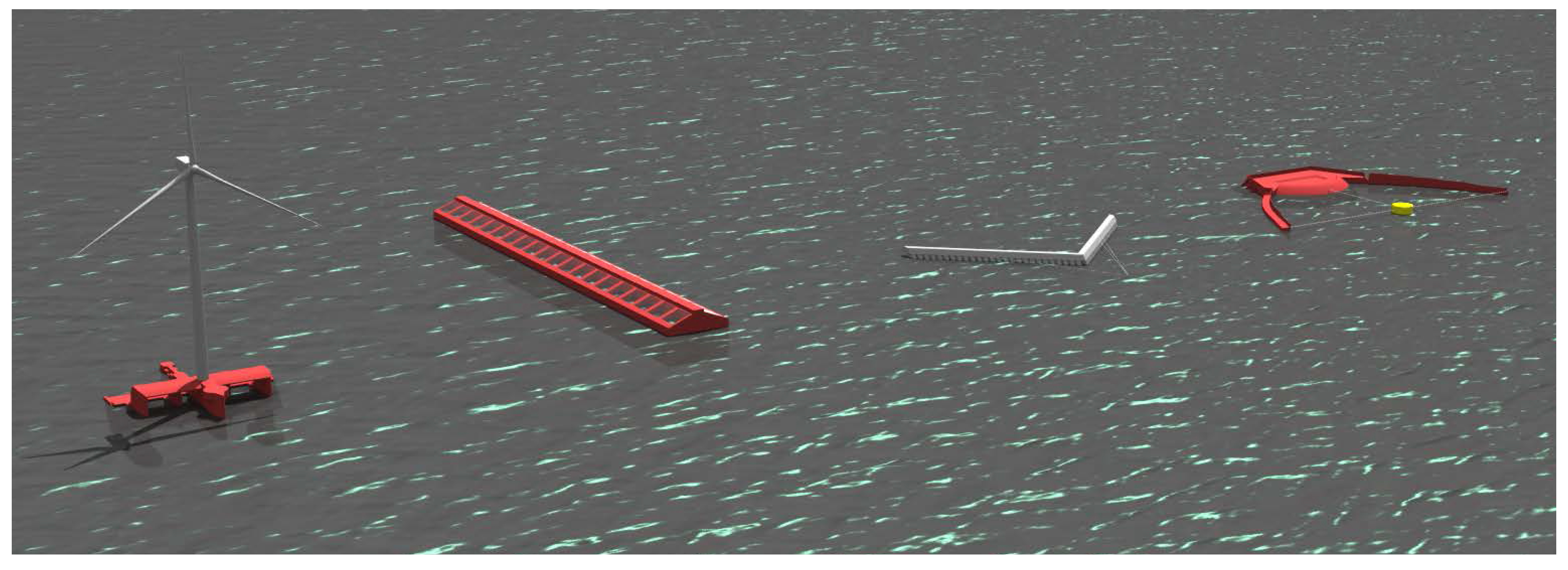
Figure 3.
The investigated WEC with the illustration of the mooring system.

Figure 4.
Motion response amplitude operators (RAOs) for the surge, heave and pitch degree of freedoms (DOFs) of the unmoored WEC calculated from the DeepC and NEMOH code.
Figure 4.
Motion response amplitude operators (RAOs) for the surge, heave and pitch degree of freedoms (DOFs) of the unmoored WEC calculated from the DeepC and NEMOH code.
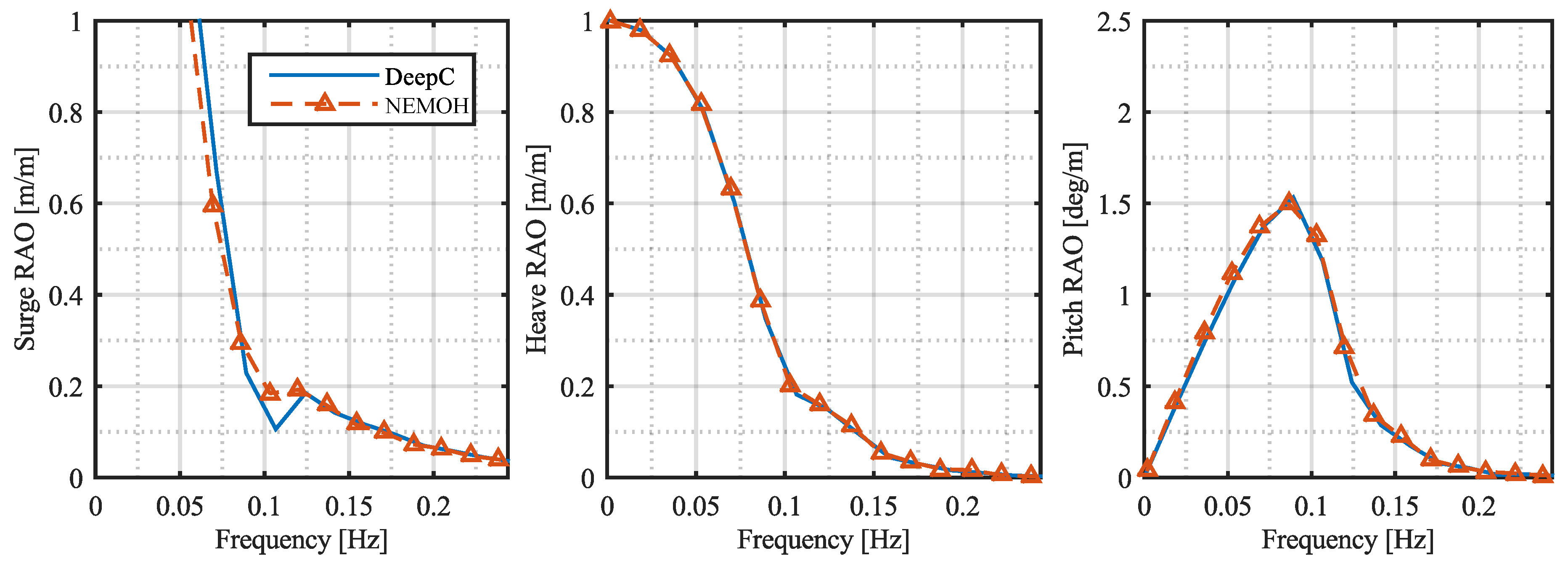
Figure 5.
Motion RAOs for the surge, heave and pitch DOF of the moored WEC obtained from both the OrcaFlex and DeepC packages.
Figure 5.
Motion RAOs for the surge, heave and pitch DOF of the moored WEC obtained from both the OrcaFlex and DeepC packages.
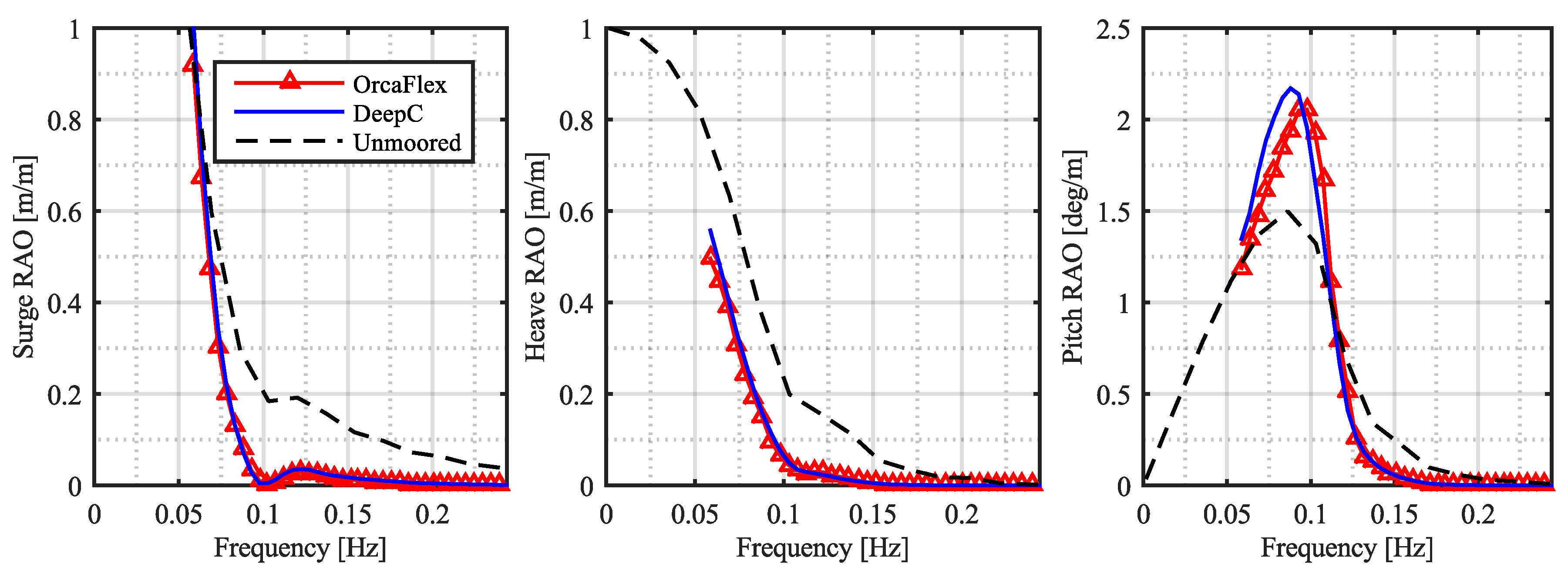
Figure 6.
Tension spectral density in the mooring line on the seaward side of the WEC.
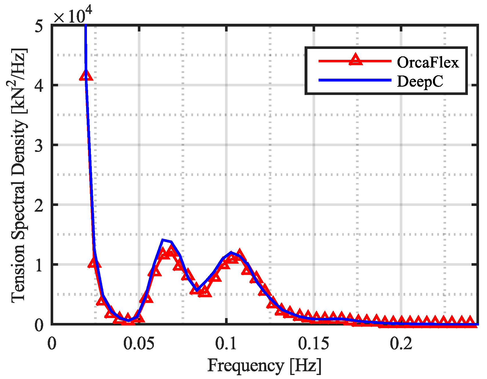
Figure 7.
Comparison of surge motion and line tension time series obtained in OrcaFlex and DeepC. (a) is for linear axial stiffness of the lines, while (b) is for non-linear stiffness.
Figure 7.
Comparison of surge motion and line tension time series obtained in OrcaFlex and DeepC. (a) is for linear axial stiffness of the lines, while (b) is for non-linear stiffness.

Table 1.
List of relevant software to consider for dynamic mooring analysis.
| # | Software Package | Developer | Ref. |
|---|---|---|---|
| 1 | Aqwa v. 15 | ANSYS Inc. | [20] |
| 2 | Flexcom v. 8.3 | Wood Group Kenny | [26] |
| 3 | MOSES | Bentley System | [27] |
| 4 | OrcaFlex v. 10.0 | Orcina Ltd. | [19] |
| 5 | ProteusDS 2015 v. 2.25.0 | Dynamic System Analysis Ltd. | [28] |
| 6 | SeaFEM v. 13.6.5 | Compass | [29] |
| 7 | DeepC v. 4.8 | DNV-GL | [30] |
Table 2.
Comparison of software capabilities concerning analysis type and ability to model wind and current. ✓ and ✗ denote respectively that the capability is available or unavailable.
Table 2.
Comparison of software capabilities concerning analysis type and ability to model wind and current. ✓ and ✗ denote respectively that the capability is available or unavailable.
| Analysis | Wind | Current | ||||
|---|---|---|---|---|---|---|
| Time domain | Coupled | Profiled | Spectrum | Profiled | Time varying | |
| Aqwa | ✓ | ✓ | ✓ | ✓ | ✓ | ✗ |
| Flexcom | ✓ | ✓ | ✓ | ✓ | ✓ | ✗ |
| MOSES | ✓ | ✓ | ✓ | ✓ | ✓ | ✗ |
| OrcaFlex | ✓ | ✓ | ✓ | ✓ | ✓ | ✓ |
| ProteusDS | ✓ | ✓ | ✓ | ✓ | ✓ | ✓ |
| SeaFEM | ✓ | ✓ | ✗ | ✗ | ✗ | ✗ |
| DeepC | ✓ | ✓ | ✓ | ✓ | ✓ | ✓ |
Table 3.
Comparison of the software capabilities of modeling waves. ✓and ✗ denote respectively that the capability is available or unavailable.
Table 3.
Comparison of the software capabilities of modeling waves. ✓and ✗ denote respectively that the capability is available or unavailable.
| Wave Theory | Hydrodynamic Analysis | |||||||
|---|---|---|---|---|---|---|---|---|
| Linear | Stokes | Stream | Irregular | Diff. /Rad. | Morison | Diff./Rad. | 2nd order | |
| Loads | Loads | Input | Wave Effects | |||||
| Aqwa | ✓ | 2nd | ✗ | ✓ | ✓ | ✓ | ✗ | ✓ |
| Flexcom | ✓ | 5th | ✓ | ✓ | ✗ | ✗ | ✓ | ✓ |
| MOSES | ✓ | 5th | ✓ | ✓ | ✓ | ✓ | ✗ | ✓ |
| OrcaFlex | ✓ | 5th | ✓ | ✓ | ✗ | ✓ | ✓ | ✓ |
| ProteusDS | ✓ | 5th | ✗ | ✓ | ✗ | ✓ | ✓ | ✗ |
| SeaFEM | ✓ | ✗ | ✗ | ✓ | ✓ | ✓ | ✗ | ✓ |
| DeepC | ✓ | 5th | ✗ | ✓ | ✓ | ✓ | ✓ | ✓ |
Table 4.
Comparison of capabilities of the implemented cable solvers in the investigated software packages. ✓and ✗ denote respectively that the capability is available or unavailable. ✳ indicates that no information could be found in the public available theory manual. LM and FE denote respectively a discrete lumped mass and finite element approach. p-th indicates that the order is user-specified.
| Dynamic Cable Solver | |||||||
|---|---|---|---|---|---|---|---|
| Tension | Bending | Torsion | Spatial | Temporal | LM/FE | Non-linear | |
| Order | Order | Stiffness | |||||
| Aqwa | ✓ | ✓ | ✗ | ✳ | ✳ | LM | ✓ |
| Flexcom | ✓ | ✓ | ✓ | 2nd | 2nd | FE | ✓ |
| MOSES | ✓ | ✓ | ✓ | 2nd | 2nd | FE | ✗ |
| OrcaFlex | ✓ | ✓ | ✓ | ✳ | 2nd | LM | ✓ |
| ProteusDS | ✓ | ✓ | ✓ | 4th | 4th | FE | ✗ |
| SeaFEM | ✓ | ✗ | ✗ | 2nd | 2nd | FE | ✗ |
| DeepC | ✓ | ✓ | ✓ | 2nd | 2nd | FE | ✓ |
| MooDy | ✓ | ✗ | ✗ | p-th | 3rd | FE | ✗ |
Table 5.
Geometrical specification of the investigated WEC.
| Parameter | Unit | Value |
|---|---|---|
| Width, W | (m) | 60.0 |
| Height, H | (m) | 12.0 |
| Length, L | (m) | 120.0 |
| Draught, d | (m) | 6.0 |
| Mass, M | (kg) | 4.428×10 |
| Estimated drag coefficient, | (-) | 1.1 |
| Center of gravity, (x,y,z) | (m) | (0.0, 0.0, 0.0) |
| Fairlead 1, (x,y,z) | (m) | (60.0, −30.0, 0.0) |
| Fairlead 2, (x,y,z) | (m) | (60.0, 30.0, 0.0) |
| Fairlead 3, (x,y,z) | (m) | (−60.0, 30.0, 0.0) |
| Fairlead 4, (x,y,z) | (m) | (−60.0, −30.0, 0.0) |
Table 6.
Mooring line and anchor specifications.
| Mooring Line Specifications | ||
| Diameter, D | (m) | 0.104 |
| Unstretched length, l | (m) | 150.0 |
| Nominal mass in air, | (kg/m) | 6.67 |
| Nominal submerged mass, | (kg/m) | 0.64 |
| Minimum breaking strength, MBS | (kN) | 2461 |
| Extension at max. load, | (%) | 27 |
| Linearized stiffness, | (kN) | 9114.8 |
| Young’s modulus, E | (MPa) | 1072.9 |
| Anchor Specifications | ||
| Center of gravity, (x,y,z) | (m) | (0.0, 0.0, 0.0) |
| Anchor 1, (x,y,z) | (m) | (166.1, −136.1.0, −30.0) |
| Anchor 2, (x,y,z) | (m) | (166.1, 136.1.0, −30.0) |
| Anchor 3, (x,y,z) | (m) | (−166.1, 136.1.0, −30.0) |
| Anchor 4, (x,y,z) | (m) | (−166.1, −136.1.0, −30.0) |
Table 7.
Characteristics of the investigated WEC.
| Parameter | Value | |
|---|---|---|
| Hydrostatic stiffness, | N/m | |
| N/rad | ||
| N/rad | ||
| Mass moment of inertia, | kg m | |
| kg m | ||
| kg m | ||
Table 8.
Sea state characteristics investigated in the case study.
| Parameter | Unit | Value |
|---|---|---|
| Water depth, | (m) | 30.0 |
| Significant wave height, | (m) | 8.3 |
| Peak wave period, | (s) | 12.3 |
| Peak enhancement factor, | (-) | 3.3 |
| Current velocity, | (m/s) | 1.0 |
| Fluid density, | (kg/m) | 1025 |
Table 9.
Comparison of simulated static mooring line tension in OrcaFlex and DeepC. The analytical value is also listed.
Table 9.
Comparison of simulated static mooring line tension in OrcaFlex and DeepC. The analytical value is also listed.
| Software Package | Static Tension in Mooring Lines |
|---|---|
| Analytical | 183.5 kN |
| OrcaFlex | 183.16 kN |
| DeepC | 183.19 kN |
Table 10.
Comparison of surge motion and line tension obtained by OrcaFlex and DeepC. The table compares exposure to current and mean wave drift separately and combined.
Table 10.
Comparison of surge motion and line tension obtained by OrcaFlex and DeepC. The table compares exposure to current and mean wave drift separately and combined.
| Exposure of Current | Mean Wave Drift | Combined | |
|---|---|---|---|
| OrcaFlex | 1.79 m/259.1 kN | 2.53 m/306.7 kN | 5.06 m/414.7 kN |
| DeepC | 1.78 m/258.4 kN | 2.27 m/288.9 kN | 5.38 m/428.5 kN |
© 2017 by the authors. Licensee MDPI, Basel, Switzerland. This article is an open access article distributed under the terms and conditions of the Creative Commons Attribution (CC BY) license (http://creativecommons.org/licenses/by/4.0/).
Share and Cite
MDPI and ACS Style
Thomsen, J.B.; Ferri, F.; Kofoed, J.P. Screening of Available Tools for Dynamic Mooring Analysis of Wave Energy Converters. Energies 2017, 10, 853. https://doi.org/10.3390/en10070853
AMA Style
Thomsen JB, Ferri F, Kofoed JP. Screening of Available Tools for Dynamic Mooring Analysis of Wave Energy Converters. Energies. 2017; 10(7):853. https://doi.org/10.3390/en10070853
Chicago/Turabian StyleThomsen, Jonas Bjerg, Francesco Ferri, and Jens Peter Kofoed. 2017. "Screening of Available Tools for Dynamic Mooring Analysis of Wave Energy Converters" Energies 10, no. 7: 853. https://doi.org/10.3390/en10070853
Note that from the first issue of 2016, this journal uses article numbers instead of page numbers. See further details here.