Investigating a Small Oil-Flooded Twin-Screw Expander for Waste-Heat Utilisation in Organic Rankine Cycle Systems

Chair of Fluidics, Faculty of Mechanical Engineering, TU Dortmund University, 44227 Dortmund, Germany
*
Author to whom correspondence should be addressed.
Energies 2017, 10(7), 869; https://doi.org/10.3390/en10070869
Submission received: 7 April 2017
/
Revised: 25 May 2017
/
Accepted: 6 June 2017
/
Published: 28 June 2017
Abstract
:Screw-type expanders offer excellent prospects for energy conversion in lower and medium power ranges, for instance as expansion engines in Rankine cycles with regard to either waste or geothermal heat recovery. With the aim of identifying the potential in organic Rankine cycle (ORC) power systems, an oil-flooded twin-screw expander without timing gears was designed and experimentally investigated in an ORC with R245fa as working fluid. Here, the scope for the experimental determination of the expander characteristic map was limited by the test rig specifications. Based on the experimental results, a multi-chamber model of the test twin-screw expander was calibrated and theoretical approaches according to mechanical and hydraulic loss calculation were applied. Consequently, the expander’s complete characteristic map could be calculated. Furthermore, relevant mechanisms influencing the operational behaviour of oil-flooded twin-screw expanders were identified and analysed in-depth.
1. Introduction
Due to the growing shortage of non-renewable fossil fuel reserves and the resulting increase in primary energy costs, underdeveloped energy potentials are increasingly moving into the focus of economic interest. Available heat sources in the field of decentralised energy systems with small and medium power ranges from 3 kW to 1.5 MW [1,2]—such as industrial exhaust gases or waste-heat in vehicle engines, geothermal or solar thermal energy—can be converted into usable mechanical power by means of expanders or turbines within a Rankine cycle.
In this context, volumetric expanders, such as sliding vane, scroll, piston, swashplate, single- or twin-screw expanders, in Rankine cycles possess clear advantages compared to turbo machines. In this context, displacement machines are capable of transforming economically small volume flows at relatively large pressure ratios [3]. Furthermore, volumetric expanders in Rankine cycles are suitable for wet-vapour operation, so that an overheating system is not essential [4]. On the one hand, the number of ORC components and the overall system costs can be reduced. On the other hand, liquid in volumetric expanders could be beneficial with regard to their operation.
Twin-screw machines, which belong to the group of multi-shaft rotary displacement machines, are characterised by relatively high energy density and efficiency, good partial load behaviour, and a fairly simple design [5]. In general, two operational modes for twin-screw machines can be distinguished: dry-running and wet-running (liquid-flooded) operation. In dry-running machines, the movement of the rotors takes place without contact between the rotor flanks in order to prevent seizing. The synchronisation of the male and female rotors is provided via mandatory timing gears. In wet-running operation, no timing gears are necessary. The transmission of torque occurs directly via contact between the rotor flanks. To lubricate the rotors and the bearings and to reduce wear, an auxiliary fluid is injected. Oil injection is common practice. In addition, the auxiliary fluid reduces noise emissions and thermal stress within the machine parts and seals structurally necessary machine clearances [6].
Hereinafter, several basic research results according to twin-screw expanders are outlined. Generally similar to gas turbines, the concept of a hot-gas screw machine for energy conversion [7] has been developed at TU Dortmund University and theoretically and experimentally investigated among others by Dosdall [8], Keller [9], and von Unwerth [10]. Intake air is compressed by means of a screw compressor, heated in a heat exchanger or a combustion chamber, and is then expanded in a screw expander. Furthermore, a twin-screw expander operating in an overheated water-steam Rankine cycle has been installed at the co-generation heat and power plant at TU Dortmund University [11]. Hütker and Brümmer have presented experimental and theoretical investigations of a dry-running twin-screw expander without timing gears in [12,13]. Kliem [14] investigated a screw expander application in a trilateral flash cycle (TFC) theoretically and experimentally. According to [1,15], the application of screw-type expanders in TFC is predicted to be a promising approach in the medium and low power operating range. With regard to TFC, overheated water is injected into the working chamber where it expands and evaporates. An approach for the theoretical investigation of screw expanders in trilateral flash cycles has been presented by Vasuthevan and Brümmer [16]. Kauder and Zellermann [17] reported a significant increase of hydraulic friction losses in terms of oil injection at high rotor tip speeds. Hence, the operating range of wet-running screw machines in terms of hydraulic losses is restricted to a rotor tip speed of maximum 40 m·s−1 [1]. Without limitations in the rotor tip speed, performance reduction in terms of oil shearing in the machine clearances exceeds the positive sealing effect of injected liquid. In this context, Harling [6] has carried out extensive experimental studies on the distribution of the injected oil in the compressor, taking into account the oil-surge hypothesis of Kauder [18]. Here, losses as a result of momentum exchange between the oil and the rotor surface have been investigated. Deipenwisch [19] has carried out further investigations into the application of oil in screw machines. Liquid injection in screw machines has also been discussed in several publications, generally with reference to compressor operation. In order to determine hydraulic friction losses in screw expander clearances using an auxiliary liquid, an analytical approach was presented by Gräßer and Brümmer with regard to water in [20] and oil in [21,22]. In [23], Nikolov and Brümmer presented a water injected twin-screw expander, focusing on the integral investigation of its operational behaviour. In addition, indicator diagrams of the water-injected twin-screw expander were analysed in order to identify the relevant influence mechanisms on operational behaviour resulting from water injection [24].
The objective of the following research task is initially to identify the potential for the application of unsynchronized twin-screw expanders with liquid injection for the utilization of waste-heat. In this context, a new small twin-screw expander without timing gears SE 34.5 has been designed at TU Dortmund University and experimentally investigated in an organic Rankine cycle. By means of the test results, simulation models have been calibrated. Based on these models, characteristic maps of SE 34.5 for R245fa as working fluid and oil as auxiliary fluid are computed. Specific aspects of the operation of oil-flooded twin-screw expanders are identified and discussed below.
2. Experimental Setup
In the following section, the experimental setup and the test twin-screw expander prototype are presented. In addition, characteristic numbers with respect to the interpretation of the operational behaviour of twin-screw expanders are listed and explained.
2.1. ORC Test Rig
Within the process of design and development of twin-screw expanders without timing gears for exhaust heat recovery in organic Rankine cycles, experimental investigations of a prototype screw expander were performed on an ORC test rig operating with R245fa as working fluid and oil lubrication at the University of Liège. A scheme of the ORC test stand is presented in Figure 1. A heating-oil boiler delivers heat input into the cycle at power ranges over the maximum required for the screw expander application. Restrictions on screw expander operation result from pressure drop in the piping limiting the back-pressure. The overall ORC liquid (R245fa and oil) mass flow is recorded by a Coriolis mass flow meter, so that no direct data for the oil mass fraction during ORC operation could be obtained. Further details of the test rig are presented in [25,26].
2.2. Twin-Screw Expander SE 34.5
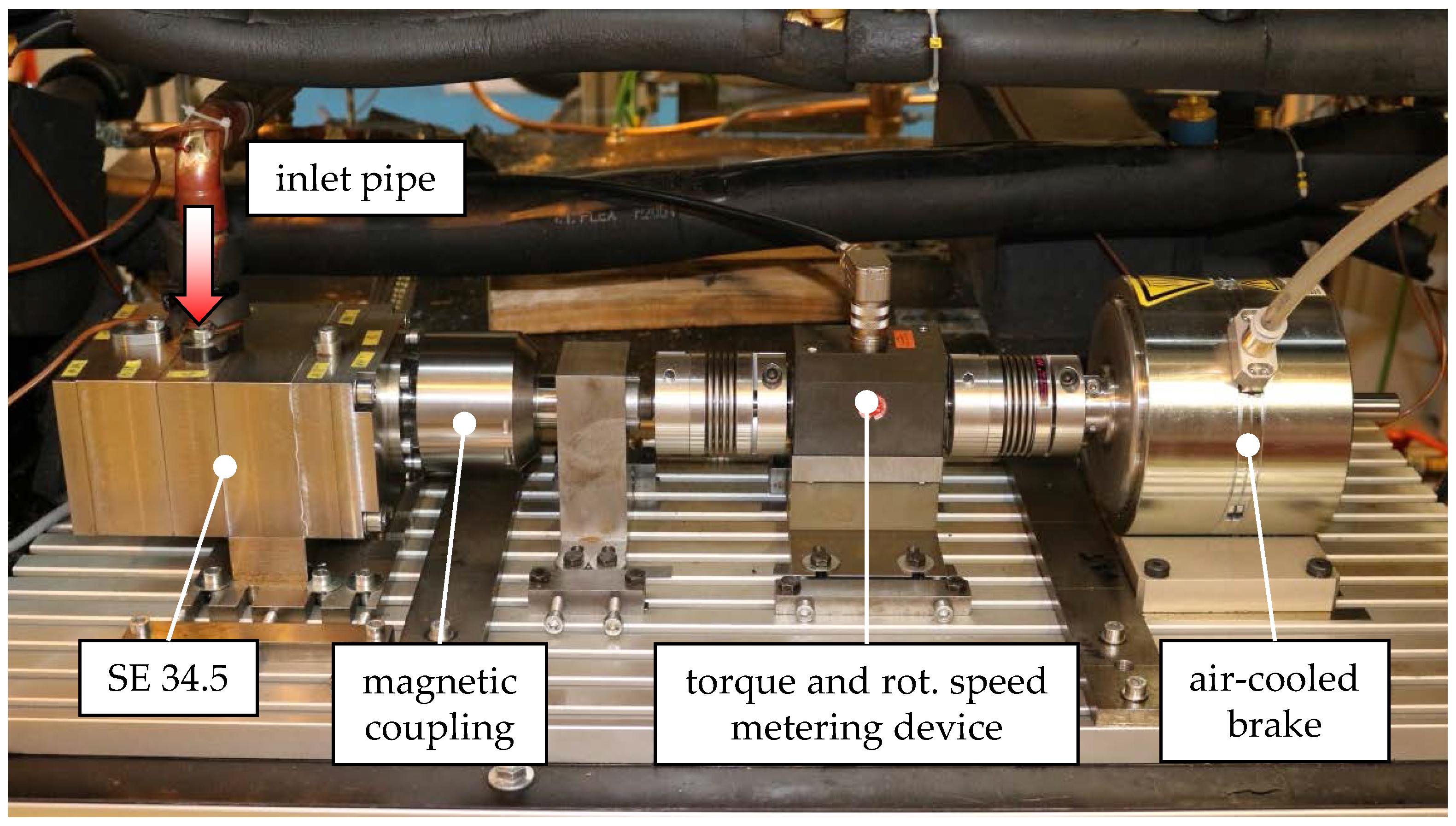
The experimental setup of the prototype twin-screw expander without timing gears SE 34.5 on the ORC test rig (Figure 1) is illustrated in Figure 2. In addition, the geometric parameters of SE 34.5, designed for a waste-heat application in an ORC power system, are listed in Table 1.
Since a hermetically sealed expander is required for operation in an ORC, a permanent-magnetic coupling is installed in order to transfer the shaft torque to the torque-metering device and the air-cooled brake. With regard to a waste-heat application, an alternator can be directly connected to the expander shaft, replacing the permanent-magnetic coupling. The experimental setup provides rotational speed and torque of SE 34.5, so the effective power of the expander can be calculated. Taking into account the operating parameters recorded on the ORC test rig, e.g., temperature and pressure at the expander inlet and outlet as well as mass flow rate, characteristic numbers for the test screw expander are calculated in order to evaluate its efficiency (see Section 2.3).
In Table 2, specifications for the oil-lubricated bearings used in SE 34.5 are listed. By means of the specific parameters and , mechanical friction losses in the bearings can be calculated according to the approach presented in Section 3.4 (Table 6).
The range of test parameters during the experimental investigations is specified in Table 3. At each inlet pressure level—7 bar, 8.8 bar, and 10 bar—the inlet temperature is varied. Within the scope of the experiments, the inlet temperature is basically varied from saturation temperature levels up to a maximum of 130 °C. Due to pressure drop in the piping, the minimum achievable expander outlet pressure depends directly on the mass flow. With regard to maximum refrigerant volume flow, at an inlet pressure of 7 bar and a temperature of 130 °C, the highest expander rotational speed of nearly 12,400 min−1 according to a male rotor tip speed of 31.5 m·s−1 is delivered. A maximum ORC mass flow , corresponding to the sum of oil mass flow and refrigerant mass flow , of nearly 0.13 kg·s−1 is measured. By means of heat balancing at the evaporator in the ORC, the oil mass fraction:
can be calculated approximately under ideal conditions, as in:
According to Figure 2, the heat flow from the heat source is calculated based on the boiler circuit temperatures and taking the density, the specific heat capacity, and the volume flow of the heating oil into account. The specific enthalpy difference of the refrigerant and of the lubricant at the evaporator are determined using the pressures and and temperatures and in the ORC. The oil mass fraction is considered during chamber model calibration in order to compare the simulated pure refrigerant mass flow with the experimental results. Nevertheless, within the following thermodynamic chamber model simulations of the screw expander, oil mass fraction is not considered due to uncertainties in the calculations (see Section 4.1, Figure 7).
2.3. Characteristic Numbers
By means of dimensionless parameters, a quantitative determination of energy conversion in twin-screw expanders is possible. Parameters and characteristic numbers for the evaluation of the operating behaviour of the test screw expander are presented in Table 4. Here, inlet and outlet pressure and temperature, mass flow, rotational speed, and male rotor torque were recorded during the tests, with the mass flow representing the overall ORC mass flow including refrigerant and lubricant.
Dividing ORC mass flow by theoretical expander mass flow, the delivery rate of the expander can be calculated. The theoretical expander mass flow is related to the chamber volume at the start of internal expansion (see Section 3.1) and to the density of the gaseous refrigerant in the intake domain. The delivery rate provides information about internal leakages in the screw expander and inlet throttling during chamber filling.
To evaluate the integral energy conversion in twin-screw expanders, the use of internal and effective isentropic efficiency is common. Indicated isentropic efficiency is calculated by referring indicated to isentropic power. In this study, indicated power is the result of thermodynamic simulations (see Section 3.3). Effective isentropic efficiency is defined as the ratio of measured effective and calculated isentropic power. By means of thermodynamic simulations with KaSim, energy conversion can be evaluated using indicated isentropic efficiency. The combination of both effective and indicated isentropic efficiency makes it possible to determine the expander mechanical efficiency, which is related to hydraulic and mechanical frictional losses inside the machine.
3. Fundamentals
In the following section, the focus is on relevant fundamentals for liquid-injected twin-screw expanders. Calculation methods with respect to the operational behaviour of twin-screw expanders are presented. In this context, the thermodynamic and fluid dynamic multi-chamber simulation tool KaSim, developed at the Chair of Fluidics, TU Dortmund University [28], is presented. By means of KaSim, the indicated power of twin-screw expanders is simulated using REFPROP 9.1 for the calculation of the refrigerant properties. Reference Fluid Thermodynamic and Transport Properties Database (REFPROP) is a program developed by the U.S. National Institute of Standards and Technology (NIST), which calculates the thermodynamic and transport properties of industrially important fluids and their mixtures [29]. In addition to indicated power, calculation approaches in terms of mechanical and hydraulic losses resulting from the application of lubricant within the working chamber are described. These calculations are carried out detached from the multi-chamber simulations by means of KaSim. Hence, an expander effective power can be calculated by subtracting mechanical and hydraulic losses from the simulated indicated power. The operation and relevant clearances of twin-screw expanders are also illustrated.
3.1. Operation of Twin-Screw Expanders
Essentially, a twin-screw expander consists of two helically intermeshing rotors with special profiles. Characteristic for the main (or male) rotor lobes is a convex profile contour, whereas the female rotor lobes are manufactured with a concave profile. The two rotors are enclosed in a casing and together form the working chambers. The chamber size varies during the working cycle depending on the angular position of the rotors. Inlet and outlet openings provide the connection between the working chambers and the high- and low-pressure domains. The positions of control edges in the expander casing, surrounding the inlet and outlet openings, determine the built-in volume ratio of the twin-screw expander. The built-in volume ratio corresponds to the ratio of the maximum volume of the working chamber related to the volume after the chamber is just disconnected from the inlet port :
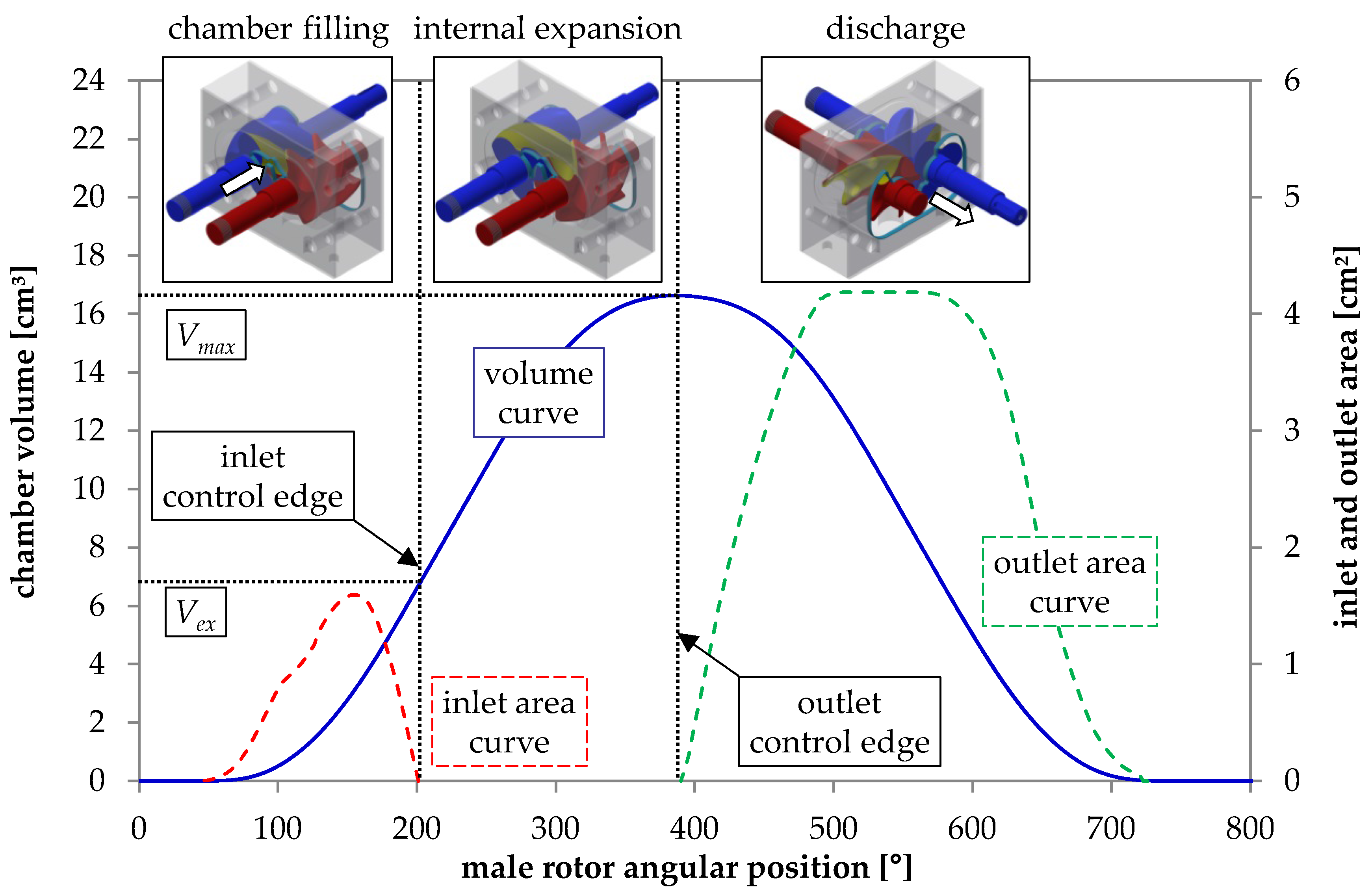
In Figure 3, a working cycle of a twin-screw expander and the characteristic development of the chamber volume as well as inlet and outlet areas depending on the angular position of the male rotor are presented. The volume curve is divided into three sections: a progressive increase until the profile intermesh relative to the working chamber is completely developed, a linear rise, and a regressive increase as the leading male and female rotor lobes turn away from each other. At the point of maximum chamber volume, the intermesh between male and female rotor lobes disappears. The volume begins to decrease as the male and female rotor lobes begin to intermesh, up to the point where the working chamber disappears.
With respect to the development of the chamber volume, the working cycle of a twin-screw expander is characterised by three specific phases: chamber filling, internal expansion, and finally the discharge of the working fluid into the low-pressure domain. During chamber filling, the pressurised working fluid flows from the high-pressure domain into the working chamber through a growing and later decreasing inlet area. As rotation progresses, the volume of the working chamber increases and work is transferred to the rotors. Chamber filling is terminated as soon as the following rotor lobes related to the working chamber pass over the intake control edges and the connection between the working chamber and the high-pressure domain is cut off. This angular position represents the start of internal expansion. Here, the further working chamber volume increases and the pressure of the trapped fluid continuously decreases. At maximum working chamber volume, the chamber-leading rotor lobes pass the outlet control edge and discharge begins. During the discharge phase of the working cycle, the chamber content is finally displaced into the low-pressure port via the outlet opening, due to the decreasing working chamber volume.
Under idealised conditions, chamber pressure during chamber filling equates with the inlet pressure. Next, an isentropic change in state can be considered during internal expansion. With respect to “design” conditions, the chamber pressure matches the outlet pressure at the end of internal expansion and the start of the discharge phase.
Considering an adiabatic working cycle under real conditions, various mechanisms influence expander operation. In terms of a dissipative chamber filling, inlet throttling losses and internal leakages via the clearances reduce the working chamber pressure. During internal expansion, internal leakages affect the working chamber state. In terms of under-expansion (chamber pressure higher than outlet pressure at the beginning of the discharge phase), a virtually isochoric pressure drop follows internal expansion. In contrast, over-expansion results in lower chamber pressure at the end of the internal expansion, so additional compression is necessary which reduces the transferred fluid energy into usable shaft power.
3.2. Clearances in Twin-Screw Expanders
The working chambers of the screw expander are limited by the surfaces of the two rotors and the adjacent surface of the rotor housing. To allow the relative movement of these components during operation clearances are essential. They prevent accidental contact between the rotating components, which would inevitably cause damage. The expander clearances have to be designed in terms of manufacturing issues and thermally induced deformation, so that operational safety is guaranteed.
The aspect of operational safety is at odds with an optimal energy conversion. The clearances connect neighbouring working chambers as well as working chambers with suction and pressure domains. This results in dissipative clearance flows, which do not always contribute to energy conversion. Clearance flows are particularly affected by the applied pressure ratio, fluid temperature, and the clearance cross-section, and they influence the quality of the energy conversion. On the one hand, internal leakages over clearances connecting high-pressure working chambers and chambers linked to the outlet domain cannot be used during energy conversion. On the other hand, clearance flows into the working chamber during internal expansion increase its pressure and, thus, the energy level within the fluid capacity. With respect to chamber refilling, these internal leakages play a part in energy conversion, albeit at a reduced energy level.
Four different clearance types can be identified in twin-screw expanders: intermesh, housing, front clearance, and the blow hole (Figure 4). The intermesh clearance describes the smallest distance between the two rotor flanks. In the case of wet-running operation, the male and female rotors have contact with one another at one or more points along the intermesh clearance, depending on the angular position of the rotors. Generally speaking, the intermesh clearance creates a direct connection between high-pressure working chambers and chambers already linked to the low-pressure port. If a high-pressure working chamber is connected with the high-pressure domain, the entire pressure difference of the machine is applied via the intermesh clearance. Hence, internal leakages over the intermesh clearance negatively affect energy conversion.
The housing clearances are located between the rotor tips and the machine casing and connect two adjacent working chambers with one another. The shape of the housing clearance differs with regard to the male and female rotors. The front clearances are located between the front rotor side and the casing, and exist on both the high- and low-pressure side of the twin-screw expander. As with the housing clearances, front clearances establish connections between adjacent working chambers. Therefore, internal leakages over the front clearances are partially useful in terms of energy conversion. In addition, front clearances connect the high-pressure chambers linked to the inlet port, and low-pressure working chambers linked to the low-pressure domain. Thus, as with intermesh clearances, the entire pressure difference is applied.
The blow holes in twin-screw expanders are shaped by the tip rounding of the rotor profile and the intersection edge in the rotor housing. Blow holes represent a theoretically unnecessary connection between adjacent working chambers. Their impact on energy conversion can be reduced by choosing a suitable rotor profile shape in terms of a small rotor tip-rounding radius. Nevertheless, leakages via blow holes on the expander’s high-pressure side (Figure 4b) are responsible for a refilling of the working chambers and, thus, are partly still utilised within the energy conversion process.
3.3. Simulation Tools
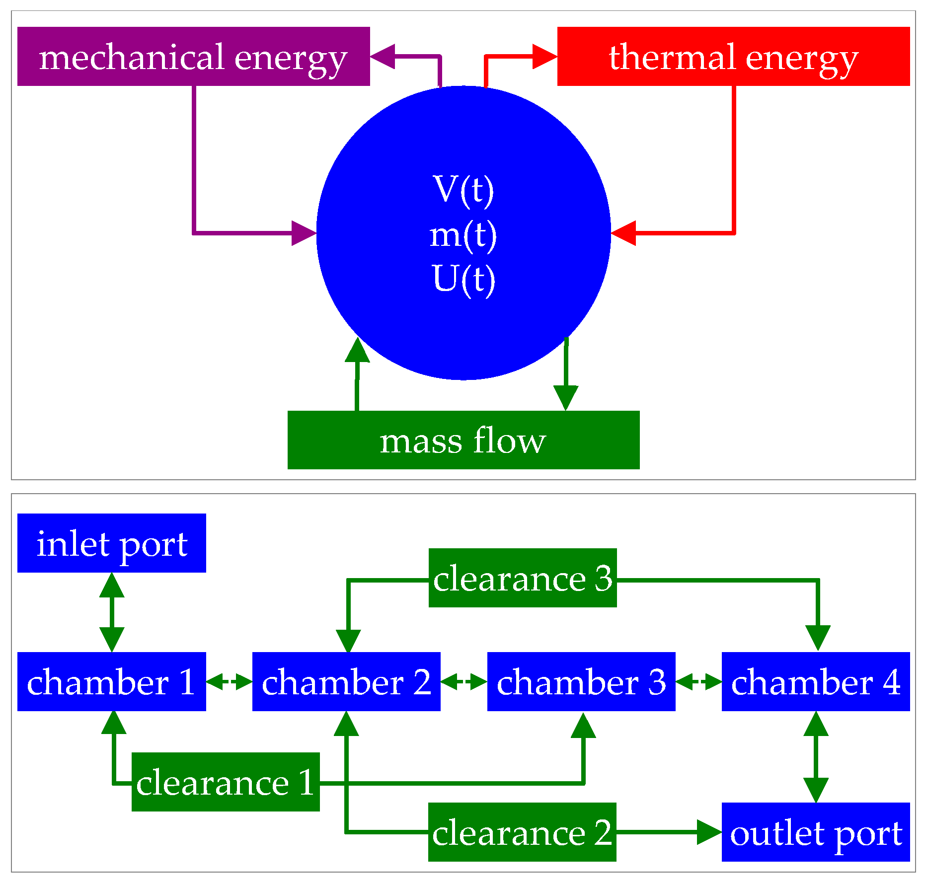
Simulations based on a chamber model represent a common method for the analysis of positive displacement machines according to one or more cyclically changing working chambers [30]. For purposes of simplicity, it is assumed that spatial gradients in the intensive state variables within a working chamber are insignificant, so the fluid conditions can thus be regarded as homogeneous. Based on this principle, the fluid condition is described by the extensive state variables of energy and mass and the related working chamber volume (Figure 5). A thermodynamic change in fluid state can occur e.g., by means of mass flows as well as mechanical or thermal energy flows. A calculation by means of the time-stepping method is carried out under consideration of the law of conservation of mass and energy [28].
Within the simulation program KaSim, the chamber model method is implemented. A fundamental distinction is made between capacities and connections. Capacities (blue boxes in Figure 5) represent storage for different physical properties, whereas connections allow an exchange between the capacities, Figure 5. The working chambers of a rotary displacement machine are an example for finite fluid capacities with time-variant volume; the clearances or inlets and outlets are examples of connections for the exchange of mass and energy [31].
In KaSim, theoretical clearance or inlet and outlet mass flow can be calculated assuming a steady isentropic nozzle flow with the cross-section :
In terms of supercritical mass flow, the maximum theoretical mass flow can be calculated to:
Considering flow coefficients α that represent flow losses in clearances or inlets and outlets, the real mass flow can be calculated as follows:
In dry-running operation, flow coefficients of about α = 0.8 have been proved to deliver an acceptable estimation of flow losses. For simulations dealing with an auxiliary fluid in the expander working chamber and its sealing effect, flow coefficients lower than 0.8 are expected.
The following chamber model simulations consider adiabatic expander operation. The thermodynamic fluid properties are calculated using the REFPROP 9.1 database, considering only gaseous refrigerant as the working fluid. Heat exchange between the working and the auxiliary fluid is not taken into account, which turns out to be a quite good first approximation within the actual study. Simulations by means of KaSim deliver time-resolved operational parameters such as chamber pressure, temperature, rotor torque, clearance mass flow, etc. Based on calculated indicator diagrams under consideration of the time-dependent chamber pressure, indicated power is calculated including fluid-mechanical loss mechanisms such as internal leakage and inlet or outlet throttling with regard to a gaseous fluid. The screw expander mass flow is also calculated, so characteristic numbers such as delivery rate and indicated isentropic efficiency are determined (see Table 4). In order to calculate effective power, hydraulic and mechanical friction losses are calculated separately as presented in Section 3.4 and subtracted from the indicated power. The lubricant temperature is assumed to be 5 K lower than the inlet temperature.
3.4. Approach for Hydraulic and Mechanical Losses
A model for the calculation of mechanical and hydraulic power losses, presented by Deipenwisch in [19], was referred to the calculation of characteristic maps for SE 34.5. Here, the effective power of the twin-screw expander can be determined by subtracting mechanical and hydraulic losses from indicated power computed by means of thermodynamic chamber model simulations.
In Figure 6, the corresponding clearance model according to the calculation of hydraulic losses is illustrated as an example with regard to the male-rotor housing clearance in screw compressors. Here, the most important parameters describing the presence of oil in the clearance are depicted. The length of the clearance , filled with oil and taking hydraulic losses into account, extends from the rotor tip at its lowest height ( at the rotor tip radius ) to the rotor lobe point at a radius according to an angle β = 15°. Here, the distance between the rotor lobe and the casing corresponds to the maximum oil film thickness with regard to the oil-surge hypothesis described in [18]. The equations considered during the mechanical and hydraulic loss calculation are listed in Table 5 and Table 6.
Hydraulic losses result from the presence of oil in the working chambers and particularly in the clearances, which are characterised by relatively small heights. Hydraulic losses consist of acceleration, friction, and impulse losses. Acceleration losses result from the acceleration of the fluid in a circumferential direction after flowing from the inlet port into the male or female rotor working chamber. Acceleration losses are related to both working and auxiliary fluid and, thus, to the entire mass flow . For the sake of simplicity, the mass flow is equally distributed between the male and female rotors. Fluid friction losses are considered only with regard to oil, and result from friction within the high-viscous oil in the narrow clearances.
The impulse losses are equivalent to the energy required to establish an oil film on the casing surface, which is set in motion by means of the gliding rotor tip until a fully developed flow profile is present in the oil film. In this context, the relevant parameters of the clearance are geometrically determined and the relative velocity of the moving boundary is taken into account. With respect to the housing clearances, the moving boundary velocity corresponds with the rotor tip speed at the rotor tip. Within the front clearances, the moving boundary velocity increases along with the rotor width at increasing distances to the rotor centre.
Mechanical losses are assumed to occur mainly in the bearings, since the calculation of mechanical friction in the profile intermesh provides relatively insignificant levels in terms of oil lubrication. Information on friction losses in bearings is provided by the manufacturer of the bearings and is a function of the rotational speed of each rotor plus bearing load, depending on the bearing type, Table 6.
4. Results
Experimental investigations of the test twin-screw expander SE 34.5 were carried out on the ORC test stand, presented in Figure 1, operating with R245fa as working fluid at the University of Liège. The purpose of the tests was to prove the suitability of a screw expander without timing gears in practice in an ORC power system with a lubricating auxiliary fluid. Due to test rig restrictions, only a partial characteristic map of the test twin-screw expander could be evaluated. Hence, in order to complement the characteristic map of SE 34.5, additional simulations with respect to the operational behaviour of the test twin-screw expander were necessary.
Based on the available test results according to R245fa as working fluid, the chamber model of SE 34.5 is calibrated in terms of flow coefficients. Here, mass flow as well as indicated power are calculated using KaSim relating to adiabatic expander operation. Additionally, mechanical and hydraulic loss models in terms of expander power loss calculations are considered. Thus, the effective power is also determined and complete characteristic maps of SE 34.5 operating in an ORC power system with lubricating auxiliary fluid are calculated. Relevant mechanisms influencing the operation of wet-running twin-screw expanders are identified.
4.1. Chamber Model Calibration
Based on the results of the experimental investigation of SE 34.5 in an ORC with R245fa as working fluid, a chamber model of the test twin-screw expander is calibrated in terms of clearance and inlet flow coefficients. Within the calibration calculations, the recorded operational parameters referring to Table 3 are considered. The calibration is carried out by a systematic variation of flow coefficients in consideration of the auxiliary fluid in the expander’s inlet and clearances. The geometrical parameters correspond to Table 1 under consideration of different housing clearance heights at the male and female rotors. During the calibration process, experimental and simulated pure refrigerant mass flows are compared. Thus, the chamber model is calibrated with regard to internal leakages and inlet throttling. At the same time, calculated and measured effective power are compared. Since a chamber model simulation provides indicated power, an additional calculation of mechanical and hydraulic losses is carried out in order to determine the effective power. The corresponding model, presented in Section 3.4, is applied with regard to R245fa and Emkarate® oil. A constant oil temperature of 5 K lower than the expander inlet temperature is taken into account in terms of hydraulic and mechanical loss calculations.
The free parameters during the calibration of the chamber model are listed in Table 7. As a reference, coefficients of 0.8 representing flow losses in the clearances, inlet, and outlet with respect to a pure gaseous flow are taken into account. A detailed variation in the flow coefficients of the front clearances at the high-pressure side, of the housing clearances, and of the inlet is carried out in order to represent flow losses in terms of a two-phase flow. Since the influence of the outlet flow coefficients on mass flow and indicated power is relatively low, it is assumed to be constant (αo = 0.8) within the following evaluations. All remaining expander clearances—blow holes, front clearances at the low-pressure side, as well as intermesh clearances—are modelled according to flow coefficients of 0.8. Especially with respect to the low-pressure front clearances and blow holes, a flow coefficient of 0.8 is appropriate due to relatively large clearance heights, where no essential sealing effect by means of the lubricant can be expected. As for the intermesh clearances, no significant blocking effect is expected, either, since significant centrifugal forces in a radial direction towards the rotor tips prevail.
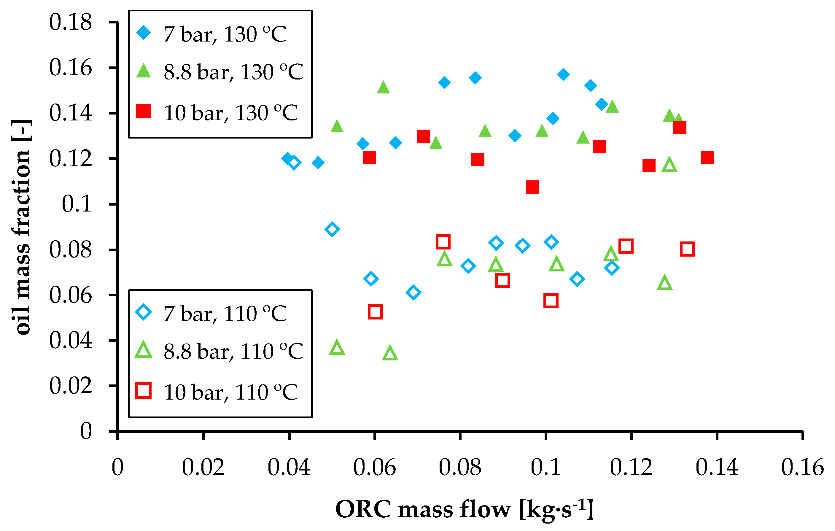
In Figure 7, a relevant dependency of the oil mass fraction (determined by means of heat balancing at the evaporator in the ORC according to Equation (2)) on refrigerant inlet temperature can be detected in the test results. In contrast, no systematic impact of overall mass flow on the oil mass fraction is obvious. An increasing oil mass fraction at a higher inlet temperature can be attributed to the declining lubricant viscosity, lower liquid wall friction as a consequence, and reduced liquid accumulation in the ORC system components. Since the amount of oil in the experiment can only be estimated, oil mass fraction in the confidence range between = 0.05 and = 0.1 is considered during the comparison of simulated and measured refrigerant mass flow. Here, both simulated and measured mass flow rates refer to the pure refrigerant.
With respect to mass flow and hydraulic-loss calculation, several conservative assumptions are made within the simulations. With regard to acceleration loss calculation (see Table 5), a constant oil mass fraction of = 0.05 is assumed, since either uncertainties according to the estimations or presumably strong fluctuation of the oil mass fraction during the tests can be observed in Figure 7. Moreover, acceleration losses represent a relatively minor part of the total hydraulic losses, so a constant oil mass fraction can be assumed for the sake of simplicity. With respect to hydraulic losses, the total volume of the high-pressure front clearances and the housing clearances of both male and female rotors are assumed to be filled with the lubricant.
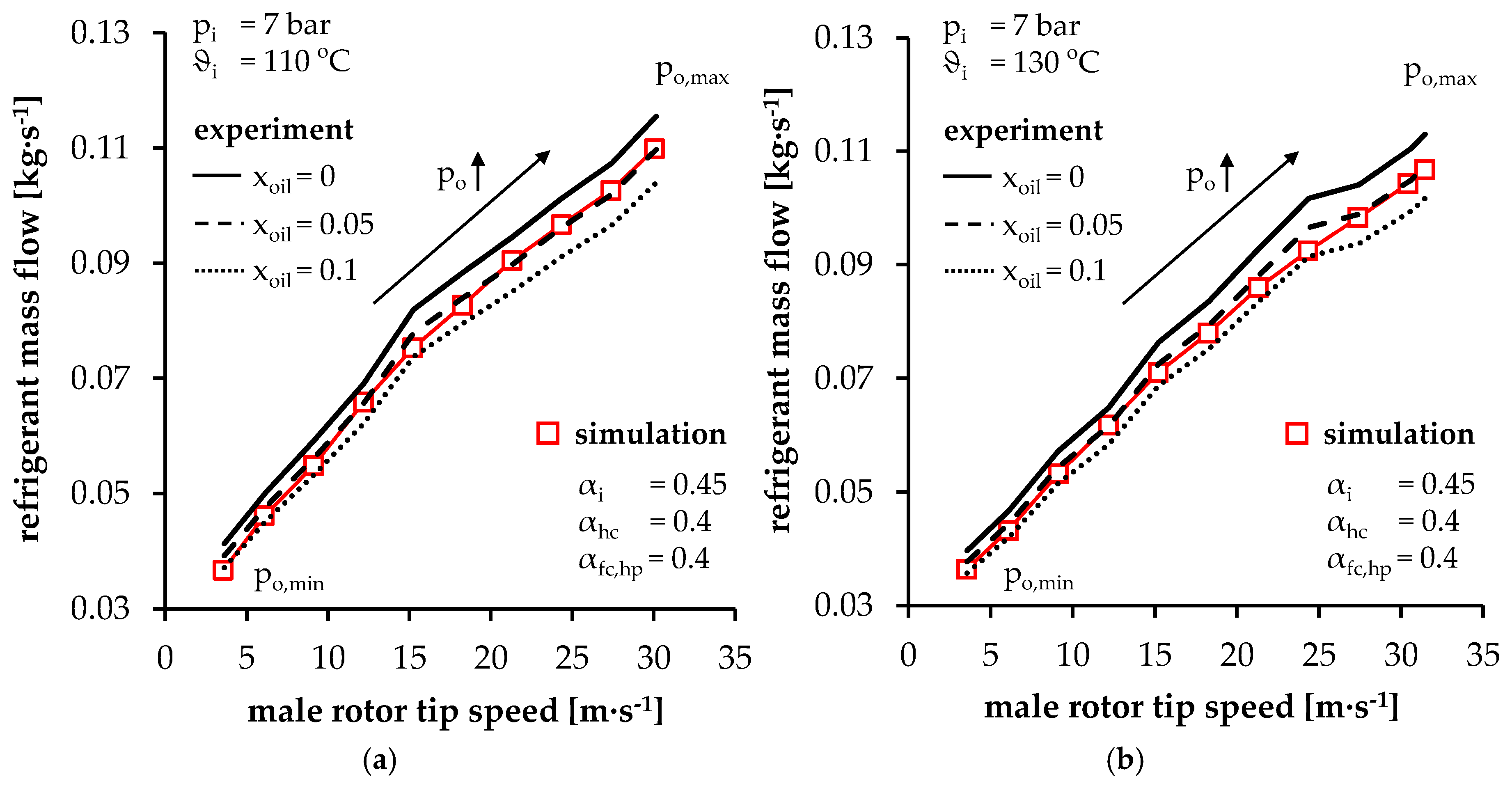
In Figure 8, the results of inlet and clearance flow coefficient variations, focusing on the accordance of simulated and measured refrigerant mass flow, are presented as an example at an inlet pressure of 7 bar and an inlet temperature of 110 °C. Based on the recorded ORC mass flow , the confidence range of the pure refrigerant mass flow, presuming an oil mass fraction of = 0, = 0.05, and = 0.1, is illustrated. If the assumed oil mass fraction goes to zero, pure refrigerant mass flow is equivalent to recorded mass flow . Assuming a constant oil mass fraction of = 0.05 or = 0.1 with regard to Figure 7, pure refrigerant mass flow in the experiments accounts for 95% or 90% of the recorded ORC mass flow rate . In Figure 8, different outlet conditions relate to each operating point due to pressure drop in the piping as mentioned earlier. Basically, increasing male rotor tip speed and mass flow result in higher outlet temperatures and pressure levels respectively. Nevertheless, no significant influence of back-pressure on mass flow is expected and, therefore, the calibration results referring to mass flow can be transferred to any back-pressure condition.
In general, expander mass flow increases at higher rotor speeds, according to both measurement and simulation, due to an increasing number of working cycles. In order to model the influence of two-phase flow via the inlet, inlet flow coefficients lower than 0.8 at constant clearance flow characteristics ( = = 0.4) are considered in Figure 8a. Different inlet flow coefficients correspond to changing throttling at the inlet in terms of two-phase flow, which affects the mass flow change depending on the rotor speed. On the one hand, decreasing inlet flow coefficients result in lower mass flow at higher rotational speeds due to increased inlet throttling. On the other hand, a variation in the inlet flow coefficient does not significantly influence the mass flow at low rotor tip speeds. Here, the working fluid mixture is characterised by relatively low flow velocity, so enough time for mass exchange via the inlet port is available. In this context, a flow coefficient of 0.6 still provides relatively high mass flow at high rotor tip speeds, since throttling losses that become more dominant under these conditions seem not to be predicted properly. A further reduction in the inlet flow coefficients results in a more adequate agreement of mass flow between experiment and simulation. An appropriate chamber model calibration in terms of mass flow results in an inlet flow coefficient of 0.45. In this context, simulated mass flow matches the measurement results in the given confidence range of oil mass fraction of 0.05 ≤ ≤ 0.1 at each male rotor tip speed under consideration.
In Figure 8b, at constant inlet flow characteristics ( = 0.45), the influence of changing clearance flow coefficients and internal leakage respectively is presented. Considering clearance flow coefficients lower than 0.8, clearance sealing by the liquid is modelled. Thus, decreasing clearance flow coefficients result in lower internal leakage and expander mass flow. Compared to the variation in Figure 8a, an offset of mass flow at each rotor speed can be observed when the clearance flow coefficients are varied. Nevertheless, mass flow variation at higher rotor tip speeds decreases with regard to declining clearance flow coefficients, since the influence of internal leakage in this operating range becomes less dominant. Clearance flow coefficients of 0.8, relating solely to gas flow, result in relatively high simulated internal leakage and mass flow respectively. Therefore, lower flow coefficients are necessary. Considering relatively low flow coefficients of 0.2, the internal leakage seems to be rather inadequately predicted, since simulated mass flow is more than 10% lower than the metered mass flow, especially at low rotor tip speeds. Considering the oil mass fraction levels illustrated in Figure 7, this deviation might be in the range between 5% and 10% at an inlet temperature of 110 °C. Hence, clearance flow coefficients of 0.4 reveal an acceptable accordance between simulation and experiment.
With respect to the comparison of simulated and experimental mass flow in Figure 8, the calibration of the chamber model delivers high-pressure front and housing clearance flow coefficients of 0.4, representing the blocking of the clearance. Inlet flow coefficients set to 0.45 correspond to increasing inlet throttling due to two-phase refrigerant-lubricant flow. Based on the inlet and clearance flow coefficients set out in Figure 8, a variation in operating parameters is carried out to test the calibration under different operating conditions. In addition to mass flow, a comparison of simulated and measured power is presented too.
In Figure 9, the calculated chamber model is evaluated in terms of simulated and measured mass flow as a function of inlet temperature and male rotor tip speed at a constant inlet pressure of 7 bar. At an inlet temperature of 130 °C in Figure 9b, the highest refrigerant volume flow and rotor speed is recorded and, hence, a wide operational range for the expander is covered. Similar to the results at an inlet temperature of 110 °C in Figure 9a, the simulated mass flow is again predicted relatively well according to the measurements, taking into account an assumed oil mass fraction between 0.05 and 0.1 in terms of both temperature levels.
In Figure 10, the relation between experimentally and theoretically determined effective power is presented, depending on rotor tip speed at different inlet temperatures and an inlet pressure of 7 bar. Simulated effective power results from indicated power calculated by means of KaSim applying mechanical and hydraulic losses, calculated as presented in Section 3.4. In this context, hydraulic losses are calculated for all clearances according to a flow coefficient smaller than 0.8 (high-pressure front clearances and housing clearances) assuming that these are completely filled with oil.
As illustrated in Figure 10, an acceptable accordance between measured and simulated power can be observed with respect to both inlet temperatures. Here, some deviations, e.g., at an inlet temperature of 130 °C and rotor tip speed of 12.2 m·s−1, can be observed. At this point, measurement uncertainties or fluctuating operational parameters related to pressure pulsations or resonances in the test cycle have to be taken into account. In general, a variation in inlet temperature indicates the accuracy of both the calibration of the chamber model, in terms of flow coefficients, and the hydraulic loss model with regard to lubricant viscosity and the geometrical parameters of the oil-structure interaction within the clearances. Different temperature and oil viscosity levels result in comparable effective power with respect to simulation and measurement.
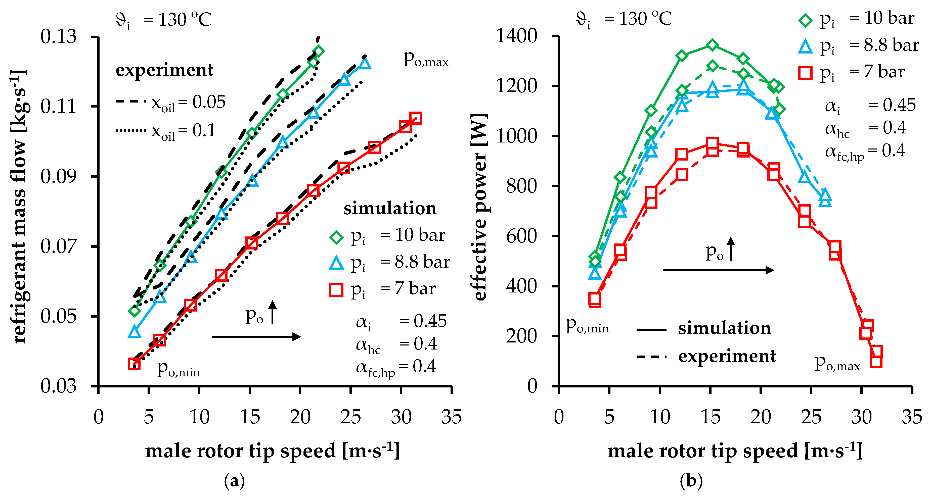
In Figure 11, measured and simulated expander mass flow (a) and effective power (b) at different inlet pressure levels and a constant inlet temperature of 130 °C are illustrated as a function of the male rotor tip speed. As with the inlet temperature variation in Figure 9, different inlet pressure levels deliver satisfying degree of accordance between simulated and measured refrigerant mass flow within the given ranges in Figure 11a. Hence, the modelling and prediction of internal leakages by means of the calibrated and then unchanged clearance and inlet flow coefficients is proved to be adequate at different pressure levels too.
As in Figure 10, with respect to the expander effective power in Figure 11b, simulation and experiment reveal comparable results. Thus, the mass flow calibration of the chamber model at only one inlet pressure proves its basic applicability with regard to the simulation of the twin-screw expander operational behaviour. Minor deviations in effective power at some operating points can be traced back, on the one hand, to measurement uncertainties or operational fluctuation as mentioned before. On the other hand, thermal deformations of the expander components offer an additional potential for discrepancies between simulation and measurement.
4.2. Characteristic Map of SE 34.5 Using R245fa as Working Fluid
In the following section, the simulated characteristic map of the twin-screw expander SE 34.5 detached from the Rankine cycle is presented with regard to R245fa as working fluid. The operational behaviour of SE 34.5 is calculated by means of the calibrated chamber model using the software KaSim and then applying models with respect to mechanical and hydraulic losses within the expander. As with the chamber model calibration in Section 4.1, a constant oil temperature of 5 K lower than the inlet temperature is considered in terms of hydraulic and mechanical loss calculation. Using the calibrated chamber model, missing operating points during the experimental investigation of the test twin-screw expander with R245fa as working fluid are added, and the characteristic map of SE 34.5 can be completed. The calculated characteristic numbers are related to the mass flow and isentropic enthalpy potential of R245fa as a pure refrigerant with no thermodynamic consideration of oil within the chamber model simulations.
In Table 8, the ORC and screw expander parameters for characteristic map simulations with regard to R245fa as working fluid are listed. In contrast to the experimental investigations, a wide range of rotational speeds at constant outlet pressure are considered. By means of the theoretical investigations, the entire range of operation of the twin-screw expander SE 34.5 with regard to mass flow, delivery rate, indicated and effective power, as well as internal and effective isentropic efficiency can be presented. Moreover, the male rotor housing clearance is considered according to its initial height of 0.05 mm, compared with the deformed clearance height of 0.1 mm during the tests and the chamber model calibration (see Table 3).
In Figure 12 mass flow (a) and delivery rate (b) of SE 34.5 are displayed at three different inlet pressure and temperature levels as a function of male rotor tip speed. In general, the mass flow depends on the change in fluid inlet density and rotor speed and does not depend significantly on the fluid conditions at the outlet. Therefore, no back-pressure variation is presented. Nevertheless, a back-pressure variation results in significantly changing chamber pressure and indicated power in contrast to a negligible change in mass flow. Thus, the influence of back-pressure variation on power and efficiency is discussed in more detail below.
As expected, mass flow increases in terms of rising rotor speed at constant inlet pressure and temperature. At lower male rotor tip speed up to almost 12 m∙s−1, mass flow increase tends to be almost linear due to negligible inlet throttling losses and relatively high internal leakages. At higher rotor speeds, inlet throttling increases and internal leakages decrease, so that the mass flow rise flattens out. At the same time, decreasing internal leakages at low rotational speeds are represented by strongly declining delivery rate. Since internal leakage becomes less dominant at higher rotor tip speeds, increasing inlet throttling losses result mainly in a decreasing delivery rate of less than one.
At constant male rotor tip speed, an increase in mass flow at higher inlet pressure and lower inlet temperatures can be traced back to increasing refrigerant density in the inlet domain. In contrast, delivery rate declines at lower inlet temperatures and constant pressure, since the speed of sound, flow velocity, and volume flow all decline. This effect applies to both clearance and inlet flow. At low rotor tip speeds, internal leakages dominate the screw expander operation. Here, a reduced inlet temperature results in decreasing internal leakage due to lower speed of sound and, thus, declining delivery rate. At higher rotor speeds, decreasing delivery rate at lower inlet temperatures can be explained in terms of lower inlet flow velocity due to reduced speed of sound and, therefore, to less effective chamber filling. With regard to increasing inlet pressure at constant inlet temperature and tip speed, a detailed examination of the fluid properties reveals an increasing flow velocity due to real gas effects (not presented here). In the case of an ideal gas, no impact of inlet pressure on delivery rate is expected.
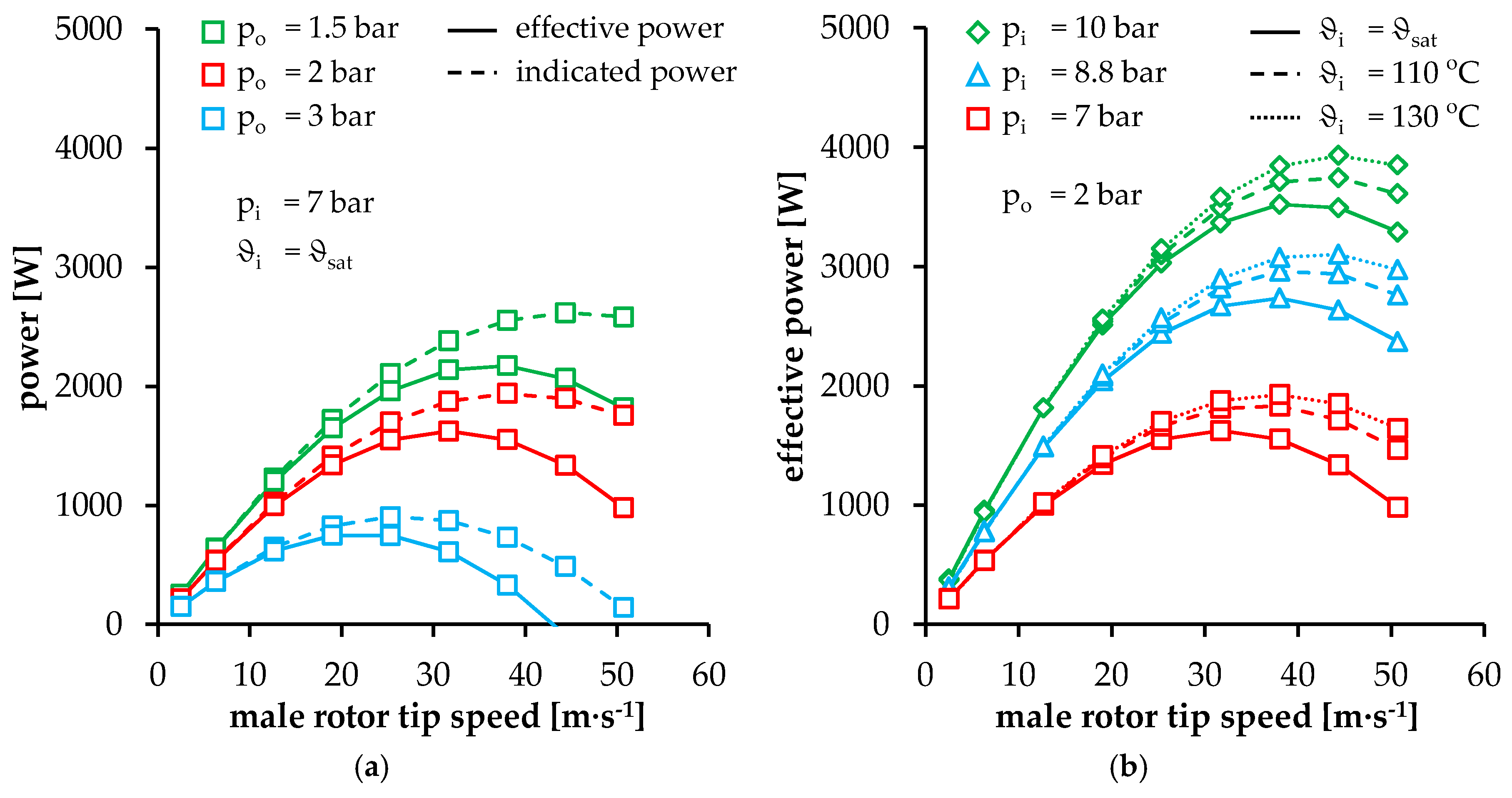
In Figure 13a, indicated and effective power are depicted as a function of male rotor tip speed and back-pressure at a constant inlet pressure of 7 bar and saturation temperature. In general, at constant inlet pressure and temperature, power output first increases, in line with rising rotor speed and mass flow respectively. Due to increasing inlet throttling, the power increase first flattens out and then actually decreases at maximum simulated tip speed, depending on the inlet conditions with respect to the expander’s constant built-in volume ratio. Increasing deviation between indicated and effective power at higher rotor speeds can be traced back to rising mechanical and hydraulic losses.
While a back-pressure variation does not significantly influence mass flow, the outlet conditions are directly responsible for over or under-expansion in the working chamber, at a constant built-in volume ratio. This affects the chamber pressure level during the working cycle and, thus, marginally, the internal leakages, but more significantly the expander power. In this context, increasing back-pressure reduces the power output due to a lower enthalpy difference over the expander. In contrast, lower back-pressure levels result in higher power output.
In Figure 13b, effective power is presented, depending on inlet pressure and temperature at constant outlet conditions. In terms of increasing inlet pressure at constant inlet temperature, an effective power increase is the result of higher inlet density and greater specific enthalpy difference in the expander. At higher rotor speeds with constant inlet pressure, a rise in effective power can be observed at increasing inlet temperatures. On the one hand, higher inlet temperatures correspond to greater specific enthalpy difference at the expander. On the other hand, increasing inlet temperatures result in higher speed of sound and flow velocity at the inlet. As illustrated in Figure 14b, inlet throttling declines and the chamber pressure rises during chamber filling. Due to this initial pressure increase, the chamber state during the following internal expansion is in accordance with permanently higher pressure levels compared to lower fluid temperatures. Hence, the indicated power increases. In addition, higher temperatures correspond to lower lubricant viscosity and hydraulic and mechanical losses respectively.
In contrast, at low rotor speeds, effective power does not depend significantly on inlet temperature at constant inlet pressure. As illustrated in Figure 14a, higher speed of sound and flow velocity at higher inlet temperatures result mainly in increasing internal leakage which does not significantly affect the chamber pressure during internal expansion. Nevertheless, a slight difference can be observed between both chamber pressures in Figure 14a and indicated power (not presented here) at different inlet temperatures and constant inlet pressure.
The different pressure levels in Figure 14a can be traced back to different ranges of influence of the clearances as a function of the angular position. At the start of internal expansion (after the rotor flanks pass over the inlet control edge), the internal leakage via the more dominant intermesh clearance in this range of angular position results in a drop in chamber pressure, since the intermesh clearance directly connects the working chamber under examination with chambers linked to the low-pressure domain. Later in the working cycle, internal leakages via the housing clearances and the blow hole, which are responsible for chamber refilling, result in increasing chamber pressure up to the level achieved at lower inlet temperatures. Before discharging the working chamber into the low pressure domain, the pressure level at higher inlet temperatures decreases again. Therefore, higher inlet temperatures at low rotor speeds and constant inlet pressure correspond to a slight decrease in power.
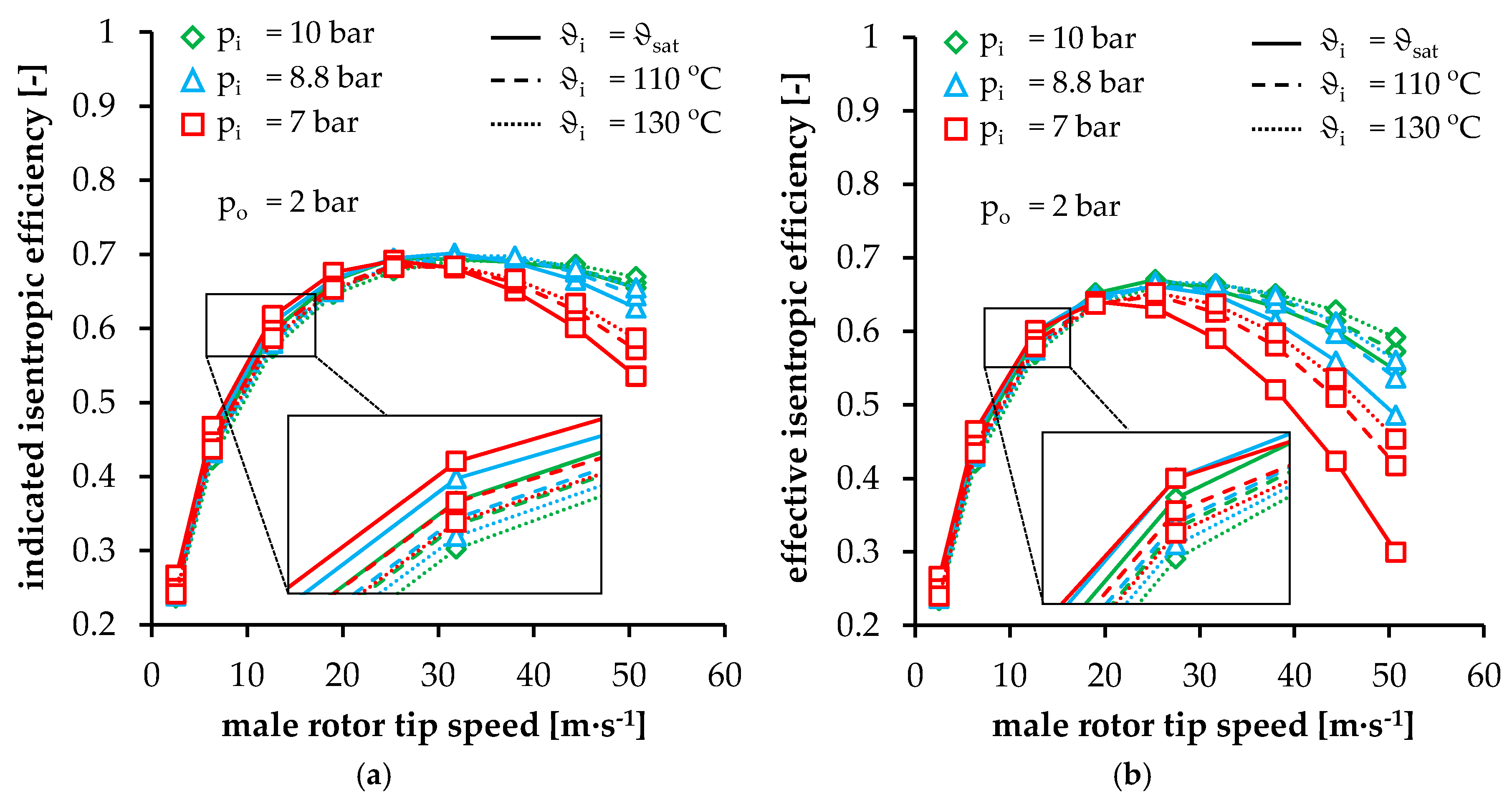
In order to quantify losses in the screw expander relative to the available fluid potential, two different characteristic numbers—internal and effective isentropic efficiency—are presented in Figure 15a,b respectively as a function of tip speed at different inlet pressure and temperature levels. According to indicated isentropic efficiency at constant inlet pressure and temperature, as illustrated in Figure 15a, the influence of inlet throttling and internal leakage can be detected. At lower rotor speeds, the domination of internal leakages is obvious, analogous to high delivery rates in Figure 12b, resulting in relatively low efficiency values. Increasing male rotor tip speed corresponds to a significant reduction in internal leakages, which can be observed in terms of increasing indicated isentropic efficiency. A maximum of indicated isentropic efficiency corresponds to varying rotor speeds depending on the inlet conditions. From the point of maximum efficiency up to the highest simulated tip speed, inlet throttling losses increase, which could result in over-expansion in the working chamber (see Figure 14b). Thus, indicated power and indicated isentropic efficiency decrease at higher rotor speeds with regard to a constant enthalpy potential of the twin-screw expander.
Considering higher inlet pressure at constant inlet temperature and low rotor speeds in Figure 15a, indicated isentropic efficiency decreases due to increasing under-expansion in the working chamber in terms of constant built-in volume ratio. In this context, the difference between the chamber pressure at the end of internal expansion and the constant back-pressure level increases. At high rotational speeds, the over-expansion in the working chamber resulting from inlet throttling declines, since the inlet pressure is increased with an increase in indicated isentropic efficiency as the result. At this point, the greatest indicated isentropic efficiency can be observed at the highest inlet pressure, since over-expansion is reduced or even avoided.
At low rotor speeds and constant inlet pressure, increasing inlet temperature corresponds to declining indicated isentropic efficiency. Basically, this can be traced back to higher speed of sound and clearance flow velocity resulting in increasing internal leakages and delivery rates as presented in Figure 12b. Furthermore, as explained earlier, a slight decrease in chamber pressure during a working cycle at increasing inlet temperatures can be detected in Figure 14a. This pressure drop in the working chamber reduces the indicated power of the twin-screw expander and its indicated isentropic efficiency.
At higher male rotor tip speeds commensurate with increasing inlet throttling losses, indicated isentropic efficiency increases with regard to higher inlet temperatures at constant inlet pressure. Here, the effect of inlet throttling is reduced by increasing the speed of sound and inlet flow velocity. Hence, the chamber pressure increases integrally and over-expansion in the working chamber is minimized (see Figure 14b) or even avoided.
To sum up, the two most significant effects on indicated isentropic efficiency in Figure 15a—internal leakages at low and inlet throttling at high rotor speeds—can be identified. In the range of optimum operating conditions, a maximum indicated isentropic efficiency of 0.7 is observed.
Comparing effective isentropic efficiency in Figure 15b with indicated isentropic efficiency in Figure 15a, a significant deviation can be observed at increasing rotor tip speeds due to increasing mechanical and hydraulic losses. Increasing lubricant viscosity at lower inlet temperatures results in higher hydraulic losses and a greater deviation between internal and effective isentropic efficiency can be observed. With respect to the hydraulic and mechanical losses, maximum effective isentropic efficiency corresponds with lower rotor speeds, compared with indicated isentropic efficiency. Depending on the operational parameters, a maximum effective isentropic efficiency of 0.67 is achieved, which is remarkably high for the small twin-screw expander under examination.
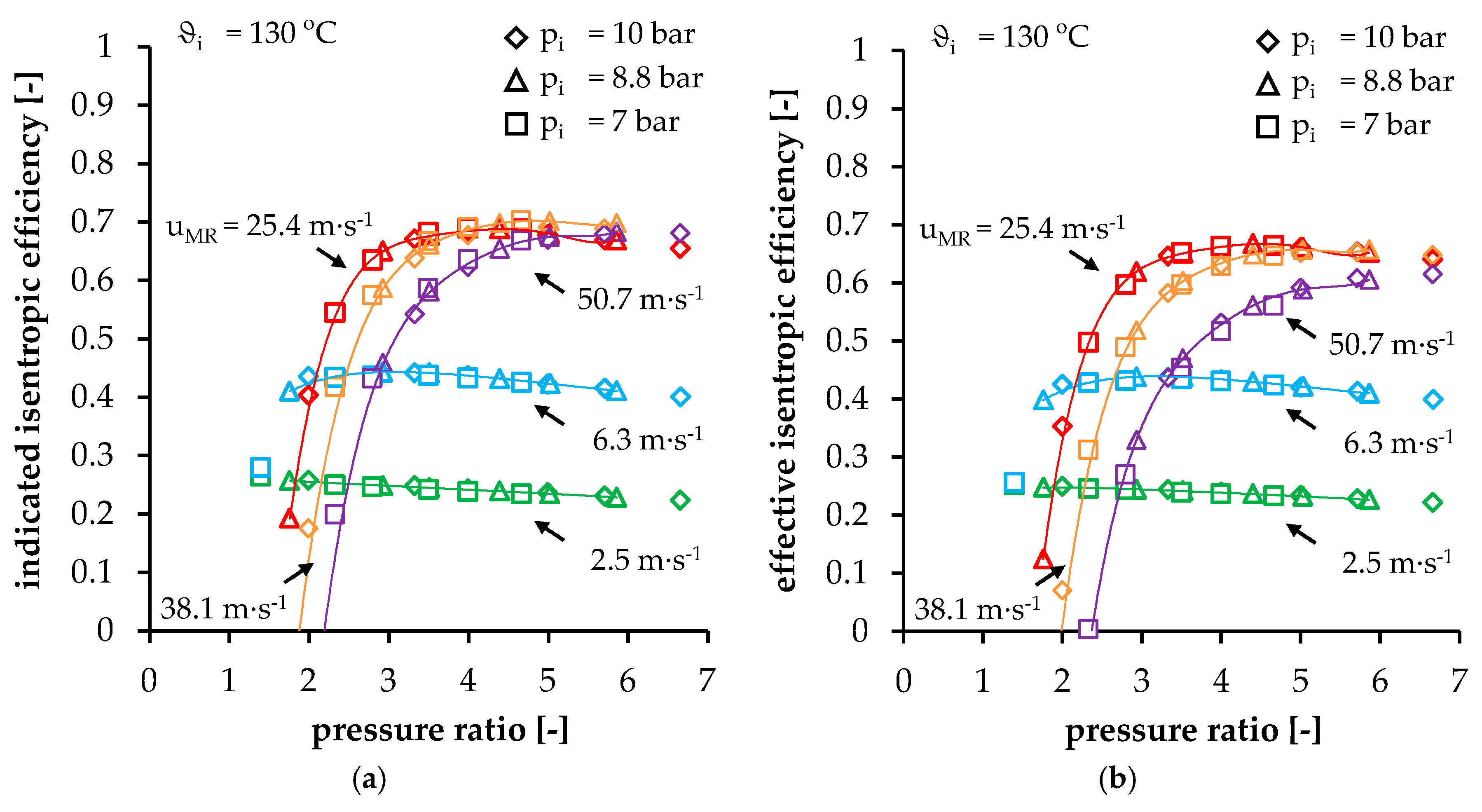
In Figure 16, indicated isentropic efficiency (a) and effective isentropic efficiency (b) are illustrated as a function of the pressure ratio over the twin-screw expander at different inlet pressure levels and male rotor tip speeds as well as a constant inlet temperature of 130 °C. Here, trend lines with a sixth-degree polynomial based on the results at an inlet pressure of 8.8 bar are used to approximate the expander efficiency. In general, no significant dependency of both characteristic numbers on inlet pressure can be detected. This is expected due to the similarity law for positive displacement machines which predicts a constant indicated isentropic efficiency at constant values of pressure ratio, Mach and Reynolds number related to rotor tip speed, and isentropic exponent [32,33].
At a constant male rotor tip speed, a maximum achievable efficiency can be observed at different pressure ratios. Taking the expander built-in volume ratio of 2.5 into account, a corresponding built-in pressure ratio of nearly 2.8 could be expected to provide maximum efficiency. Nevertheless, at constant low rotor tip speeds, the maximum expander efficiency is achieved at a pressure ratio lower than the built-in pressure ratio. Here, internal leakages result in increasing chamber pressure during internal expansion and under-expansion respectively. Vice versa, at high rotor tip speeds, the pressure ratio providing maximum efficiency is higher than the built-in pressure ratio due to increasing inlet throttling and over-expansion. Hence, the overall efficiency maximum corresponds to pressure ratios higher than the designed built-in pressure ratio of the screw expander.
5. Discussion
Based on a calibrated chamber model, a complete characteristic map of the investigated oil-flooded twin-screw expander SE 34.5 for an ORC power system application has been calculated. Within further studies, a consideration of different working fluids can be taken into account. In this context, the characteristics of different working fluids with respect to e.g., speed of sound or mass flow density in combination with optimum operational parameters can be analysed. Moreover, the use of different lubricants can be investigated in detail with reference to viscosity and clearance sealing effects. Since a wet-steam application for twin-screw expanders is expected to be very promising, further experimental investigations based on low-viscosity liquids in the working chamber and clearances as well as modelling the impact of multi-phase flow (gaseous and liquid refrigerant as well as lubricant) should be pursued.
6. Conclusions
Within the framework of this paper, the operational behaviour of a small oil-flooded twin-screw expander in ORC power systems is theoretically and experimentally investigated in depth and relevant influence mechanisms are identified. By means of test results on an ORC rig at the University in Liège, a chamber model of the test screw expander SE 34.5 was calibrated by means of the measured and simulated mass flow at one inlet pressure. Subsequently, a complete characteristic map was calculated.
During the chamber model calibration, inlet and clearance flow coefficients were adjusted in terms of an appropriate calculation of mass flow and internal leakages considering the inlet throttling and sealing effect of oil on the expander operation. At low rotational speeds, reducing the clearance flow coefficients in accordance with lower internal leakages due to the sealing effect of the oil, an acceptable match between simulated and measured mass flow was achieved. At higher rotational speeds, the increasing impact of the oil on inlet throttling could be adequately predicted by reducing the inlet flow coefficients. Finally, applying a mechanical and hydraulic loss model and considering the computed indicated power by means of chamber model simulations, the calculated power was compared with the test results. A satisfactory degree of concordance between simulation and experiment was achieved.
Based on the calibrated chamber model and considering the mechanical and hydraulic loss models, the characteristic map of the test screw expander was completed, and relevant impact mechanisms were pointed out. In particular, a rather high effective isentropic efficiency of 0.67 was calculated taking into account the relatively small size of the investigated twin-screw expander SE 34.5.
Acknowledgments
This research on small twin-screw expanders for waste-heat recovery in ORC power systems was supported by Valeo Thermal Systems. We are very thankful to Régine Haller and Stefan Karl from Valeo Thermal Systems who provided expertise that greatly assisted the research from the very beginning. Furthermore, very special thanks goes out to Vincent Lemort, Olivier Dumont, and everyone at the University in Liège who took part in the preparation and accomplishment of the twin-screw expander tests for their kindly support and all the productive and intriguing discussions.
Author Contributions
Alexander Nikolov and Andreas Brümmer conceived and designed the experiments; Alexander Nikolov performed the experiments and carried out the simulations; Alexander Nikolov and Andreas Brümmer analysed the results and interpreted the data; Alexander Nikolov wrote the paper and the final review was done by Andreas Brümmer. All authors revised and approved the publication.
Conflicts of Interest
The authors declare no conflict of interest.
Abbreviations
The following symbols and abbreviations are used in this manuscript:
List of Symbols
| Symbol | Unit | Description |
| A | [m2] | area, cross-section |
| a | [m] | axis-centre distance |
| C0 | [N] | basic static load |
| d | [m] | diameter |
| f0 | [-] | bearing coefficient for speed-dependent frictional torque |
| f1 | [-] | specific bearing coefficient |
| h | [m] | height |
| h | [m2∙s−2, J∙kg−1] | specific enthalpy |
| l | [m] | length |
| M | [Nm] | torque |
| [Nm] | speed-dependent frictional torque | |
| [Nm] | load-dependent frictional torque | |
| m | [kg] | mass |
| [kg∙s−1] | mass flow | |
| n | [s-1] | rotational speed |
| p | [Pa, bar] | pressure |
| P | [W] | power |
| [-] | equivalent static bearing load (radial/axial) | |
| [-] | decisive load for frictional torque (radial/axial) | |
| [W] | heat flow | |
| R | [m] | radius |
| R | [J∙kg−1∙K−1] | specific gas constant |
| s | [m] | rotor lead |
| t | [s] | time |
| T | [K] | temperature |
| u | [m∙s−1] | rotor tip speed |
| U | [J] | internal energy |
| v | [-] | volume ratio |
| v | [m∙s−1] | velocity |
| V | [m3] | volume |
| w | [m] | width |
| W | [J] | work |
| x | [-] | mass fraction |
| z | [-] | number of rotor lobes |
| α | [-] | flow coefficient |
| β | [°] | lobe angle |
| Δ | [-] | difference |
| γ | [°] | angle |
| δ | [m] | maximum oil film thickness |
| ρ | [kg∙m−3] | density |
| τ | [N∙mm−2] | shear stress |
| ω | [rad∙s−1] | angular velocity |
| ϕ | [°] | wrap angle |
| [W] | loss power | |
| ϑ | [°C] | temperature |
| η | [-] | efficiency |
| η | [kg∙m−1∙s−1] | dynamic viscosity |
| κ | [-] | isentropic exponent |
| [-] | delivery rate | |
| ν | [m2∙s−1] | kinematic viscosity |
List of Abbreviations and Indices
| Abbrev./Index | Description | Abbrev./Index | Description |
| acc | acceleration | imp | impulse |
| av | average | l | lobe |
| b | bearing | lp | low pressure |
| bh | blow hole | max | maximal |
| c | clearance | min | minimal |
| cr | critical | MR | male rotor |
| cs | clearance surface | o | outlet |
| e | effective | ORC | organic Rankine cycle |
| evap | evaporator | rel | relative |
| ex | expansion | s | isentropic |
| exp | expander | sat | saturation |
| fc | front clearance | SE | screw expander |
| FR | female rotor | SRM | Svenska Rotor Maskiner |
| fric | frictional | t | rotor tip |
| hc | housing clearance | TFC | trilateral flash cycle |
| ho | heating oil | th | theoretical |
| hp | high pressure | VG | viscosity grade |
| i | inlet, internal, indicated, built-in | φ | loss |
| ic | intermesh clearance |
References
- Ohman, H.; Lundqvist, P. Screw expanders in ORC applications, review and a new perspective. In Proceedings of the 3rd International Seminar on ORC Power Systems, Brussels, Belgium, 12–14 October 2015. [Google Scholar]
- Hütker, J. Energiewandlung in Trockenlaufenden Schraubenmotoren. Ph.D. Thesis, TU Dortmund University, Dortmund, Germany, November 2016. [Google Scholar]
- Kauder, K. Anhang-Arbeitsweise der Schraubenmaschine. In Schraubenmaschinen Nr. 1: Betriebssicherheit und Steuerungen von Schraubenmaschinen; Kauder, K., Ed.; FG Fluidenergiemaschinen: Dortmund, Germany, 1993. [Google Scholar]
- Brümmer, A. Energy efficiency—Waste heat utilisation with screw expanders. Prozesstechnik und Komponenten 2012, 120–126. [Google Scholar]
- Rinder, L. Schraubenverdichter; Springer: Wien, Austria; New York, NY, USA, 1979. [Google Scholar]
- Harling, H.B. Untersuchungen zur Ölverteilung in Schraubenkompressoren mit Schmiermitteleinspritzung. Ph.D. Thesis, Universität Dortmund, VDI-Verlag, Düsseldorf, Germany, 1994. [Google Scholar]
- Kauder, K. Die Heissgasschraubenmaschine-ein neues Antriebskonzept. Motortechnische Zeitschrift (MTZ), Band 47 (1986) Heft 7/8; Franckh’sche Verlagshandlung: Stuttgart, Germany, 1986; pp. 269–274. [Google Scholar]
- Dosdall, H. Simulation und Untersuchung des stationären und instationären Betriebsverhaltens der Heißgasschraubenmaschine; Universität Dortmund: Dortmund, Germany, 1996. [Google Scholar]
- Keller, G. Simulationsgestützte Entwicklung des Motors einer Heißgasschraubenmaschine. Ph.D. Thesis, Universität Dortmund, VDI-Verlag, Düsseldorf, Germany, 1998. [Google Scholar]
- Unwerth, T. Experimentelle Verifikation eines Simulationssystems für eine GASSCREW. Ph.D. Thesis, Universität Dortmund, Dortmund, Germany, November 2002. [Google Scholar]
- Kauder, K.; Kliem, B.; Piatkowski, R. Schraubenmotor-Anlage: Teil der Energieversorgung der Universität Dortmund. In Schraubenmaschinen Nr. 4: Schraubenmotoren; Kauder, K., Ed.; Universität Dortmund, FG Fluidenergiemaschinen: Dortmund, Germany, 1996; pp. 84–97. [Google Scholar]
- Hütker, J.; Brümmer, A. Experimental and theoretical investigation of dry running high-speed screw motors. In Proceedings of the International Rotating Equipment Conference, Düsseldorf, Germany, 27–28 September 2012; pp. 75–86. [Google Scholar]
- Hütker, J.; Brümmer, A. Physics of a dry running unsynchronized twin screw expander. In Proceedings of the 8th International Conference on Compressors and their Systems, London, UK, 9–10 September 2013; pp. 407–416. [Google Scholar]
- Kliem, B. Grundlagen des Zweiphasen-Schraubenmotors. Ph.D. Thesis, Universität Dortmund, Dortmund, Germany, October 2005. [Google Scholar]
- Smith, I.K. Development of the trilateral flash cycle system Part 1: Fundamental considerations. Proc. Inst. Mech. Eng. A J. Power Energy 1993, 207, 179–194. [Google Scholar] [CrossRef]
- Vasuthevan, H.; Brümmer, A. Thermodynamic Modeling of Screw Expander in a Trilateral Flash Cycle. In Proceedings of the 23rd International Compressor Engineering Conference at Purdue, West Lafayette, IN, USA, 11–14 July 2016. [Google Scholar]
- Zellermann, R.; Kauder, K. Einspritzflüssigkeiten im Schraubenmotor. In Schraubenmaschinen '94, Schraubenkompressoren, Schraubenlader, Schraubenmotoren. Tagung Dortmund, 5 und 6 Oktober 1994; VDI-Verlag: Düsseldorf, Germany, 1994; pp. 153–174. [Google Scholar]
- Kauder, K. Das Öl im Schraubenkompressor—ein Faktor für optimale Betriebsverhaeltnisse; Pumpen Vakuumpumpen Kompressoren: Nürnberg, Germany, 1987; pp. 38–44. [Google Scholar]
- Deipenwisch, R. Ein Beitrag zum Einsatz von Öl als Konstruktionselement in Schraubenmaschinen. Ph.D. Thesis, Universität Dortmund, VDI Verlag, Dusseldorf, Germany, 2000. [Google Scholar]
- Gräßer, M.; Brümmer, A. An analytic model of the incompressible one-phase clearance flow in liquid injected screw expanders. In Proceedings of the International Conference on Screw Machines, Dortmund, Germany, 23–24 September 2014; pp. 71–89. [Google Scholar]
- Gräßer, M.; Brümmer, A. Influence of liquid in clearances on the operational behaviour of twin screw expanders. IOP Conf. Ser. Mater. Sci. Eng. 2015, 90, 12060. [Google Scholar] [CrossRef]
- Gräßer, M.; Brümmer, A. Influence of water and oil clearance flow on the operational behavior of screw expanders. Proc. Inst. Mech. Eng. E J. Proc. Mech. Eng. 2016, 231, 38–46. [Google Scholar] [CrossRef]
- Nikolov, A.; Brümmer, A. Influence of water injection on the operating behaviour of screw expanders: Experimental investigation. In Proceedings of the International Conference on Screw Machines, Dortmund, Germany, 23–24 September 2014; pp. 43–60. [Google Scholar]
- Nikolov, A.; Brümmer, A. Analysis of Indicator Diagrams of a Water Injected Twin-shaft Screw-type Expander. In Proceedings of the 23rd International Compressor Engineering Conference at Purdue, West Lafayette, IN, USA, 11–14 July 2016. [Google Scholar]
- Georges, E.; Declaye, S.; Dumont, O.; Quoilin, S.; Lemort, V. Design of a small-scale organic Rankine cycle engine used in a solar power plant. Int. J. Low-Carbon Technol. 2013, 8, i34–i41. [Google Scholar] [CrossRef]
- Dickes, R.; Dumont, O.; Declaye, S.; Quoilin, S.; Bell, I.; Lemort, V. Experimental Investigation Of An ORC System For A Micro-Solar Power Plant. In Proceedings of the 22nd International Compressor Engineering Conference at Purdue, West Lafayette, IN, USA, 14–17 July 2014. [Google Scholar]
- Schaeffler Technologies AG & Co. KG. Schmierung von Wälzlagern, 2013. Available online: http://www.schaeffler.com/remotemedien/media/_shared_media/08_media_library/01_publications/schaeffler_2/tpi/downloads_8/tpi_176_de_de.pdf (accessed on 1 March 2016).
- Janicki, M. Modellierung und Simulation von Rotationsverdrängermaschinen. Ph.D. Thesis, Universität Dortmund, Dortmund, Germany, December 2007. [Google Scholar]
- Lemmon, E.W.; Huber, M.L.; McLinden, M.O. NIST Standard Reference Database 23: Reference Fluid Thermodynamic and Transport Properties-REFPROP, Version 9.1; National Institute of Standards and Technology, Standard Reference Data Program: Gaithersburg, MD, USA, 2013. [Google Scholar]
- Janicki, M.; Kauder, K. Adiabatic Modelling and Thermodynamic Simulation of Rotary Displacement Machines. In Proceedings of the International Conference on Compressors and Their Systems, London, UK, 7–10 September 2003. [Google Scholar]
- Kauder, K.; Janicki, M. Thermodynamische Simulation von Rotationsverdrängern mit Hilfe des Programmsystems KaSim. In Schraubenmaschinen Nr. 10: Neues Kammermodell, Optimierung von Rotorgeometrien, Spaltströmungen, Schraubenmotoren, Schraubenspindel-Vakuumpumpen; Kauder, K., Ed.; Universität Dortmund: Dortmund, Germany, 2002; pp. 5–16. [Google Scholar]
- Dreißig, B. Ein Beitrag zur Auslegung von trockenlaufenden Schraubenmotoren. Ph.D. Thesis, Universität Dortmund, Dortmund, Germany, 1989. [Google Scholar]
- Utri, M.; Brümmer, A. Energy potential of dual lead rotors for twin screw compressors. In Proceedings of the 10th International Conference on Compressors and their Systems, London, UK, 11–13 September 2017. [Google Scholar]
Figure 1.
Simplified ORC test rig scheme adapted from [26] with permission from © 2017 Thermodynamics Laboratory, University of Liège, 2017.
Figure 1.
Simplified ORC test rig scheme adapted from [26] with permission from © 2017 Thermodynamics Laboratory, University of Liège, 2017.
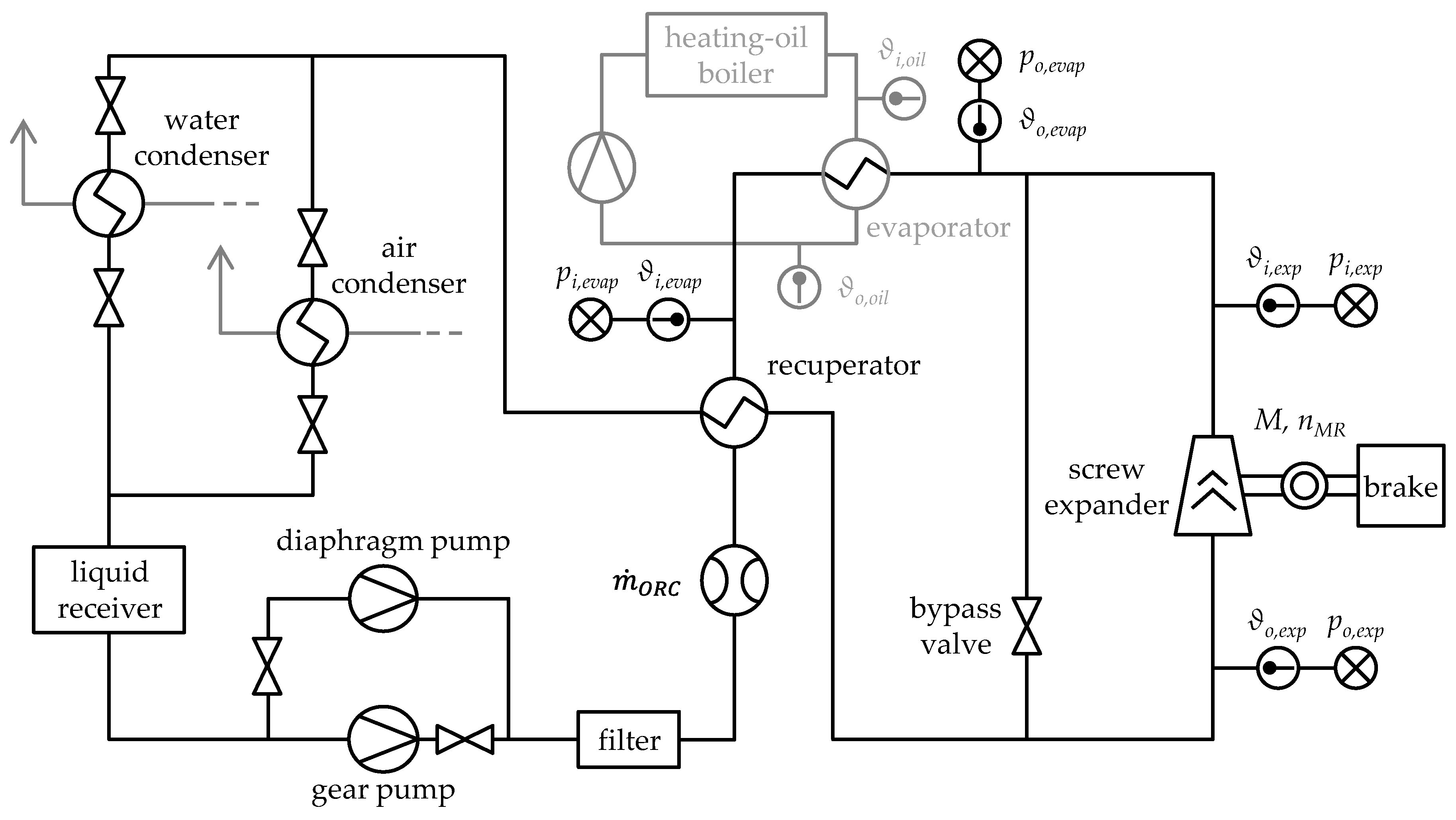
Figure 2.
Twin-screw expander SE 34.5 on the ORC test rig at the University of Liège.

Figure 3.
Volume curve, inlet and outlet area, as well as characteristic phases of a working cycle of the test twin-screw expander SE 34.5.
Figure 3.
Volume curve, inlet and outlet area, as well as characteristic phases of a working cycle of the test twin-screw expander SE 34.5.

Figure 4.
Clearances in twin-screw expanders—intermesh clearance (a), housing and front clearances (low-pressure (lp) side, high-pressure (hp) side) (b), blow holes (hp) (c).
Figure 4.
Clearances in twin-screw expanders—intermesh clearance (a), housing and front clearances (low-pressure (lp) side, high-pressure (hp) side) (b), blow holes (hp) (c).
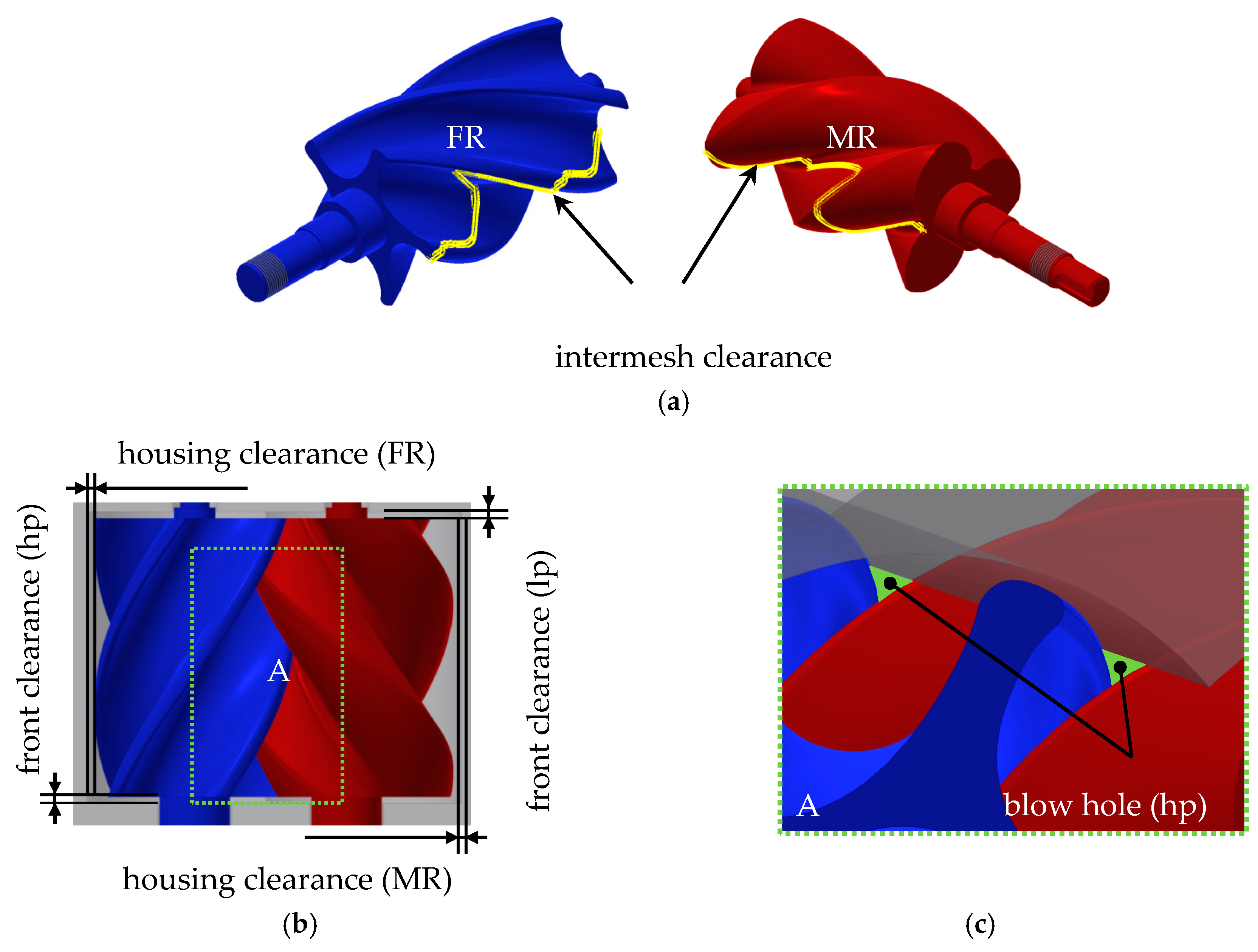
Figure 5.
Abstract model of an exemplary rotary displacement machine in KaSim.

Figure 6.
Modelling of the male rotor housing clearance in terms of hydraulic loss calculation.
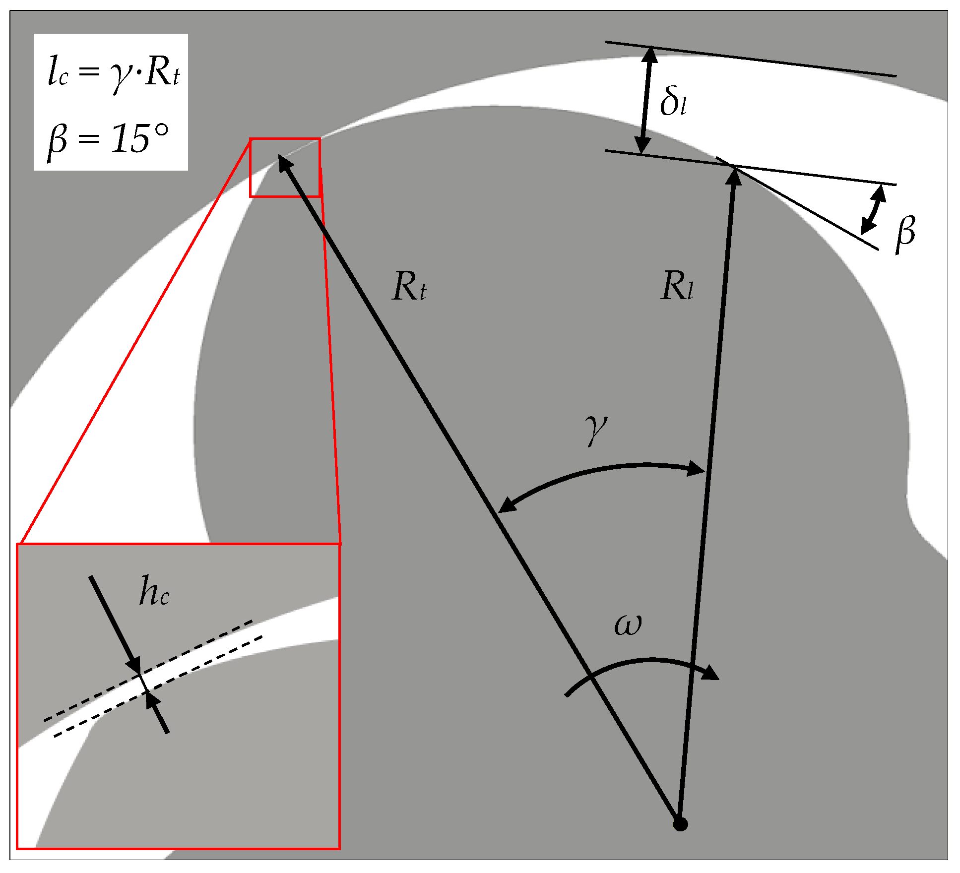
Figure 7.
Determination of oil mass fraction as a function of Coriolis mass flow (R245fa and oil) at various inlet pressures and temperatures.
Figure 7.
Determination of oil mass fraction as a function of Coriolis mass flow (R245fa and oil) at various inlet pressures and temperatures.

Figure 8.
Simulated and measured refrigerant mass flow as a function of male rotor tip speed at a constant inlet pressure of 7 bar and a temperature of 110 °C according to inlet (a) and clearance flow coefficient variation (b).
Figure 8.
Simulated and measured refrigerant mass flow as a function of male rotor tip speed at a constant inlet pressure of 7 bar and a temperature of 110 °C according to inlet (a) and clearance flow coefficient variation (b).
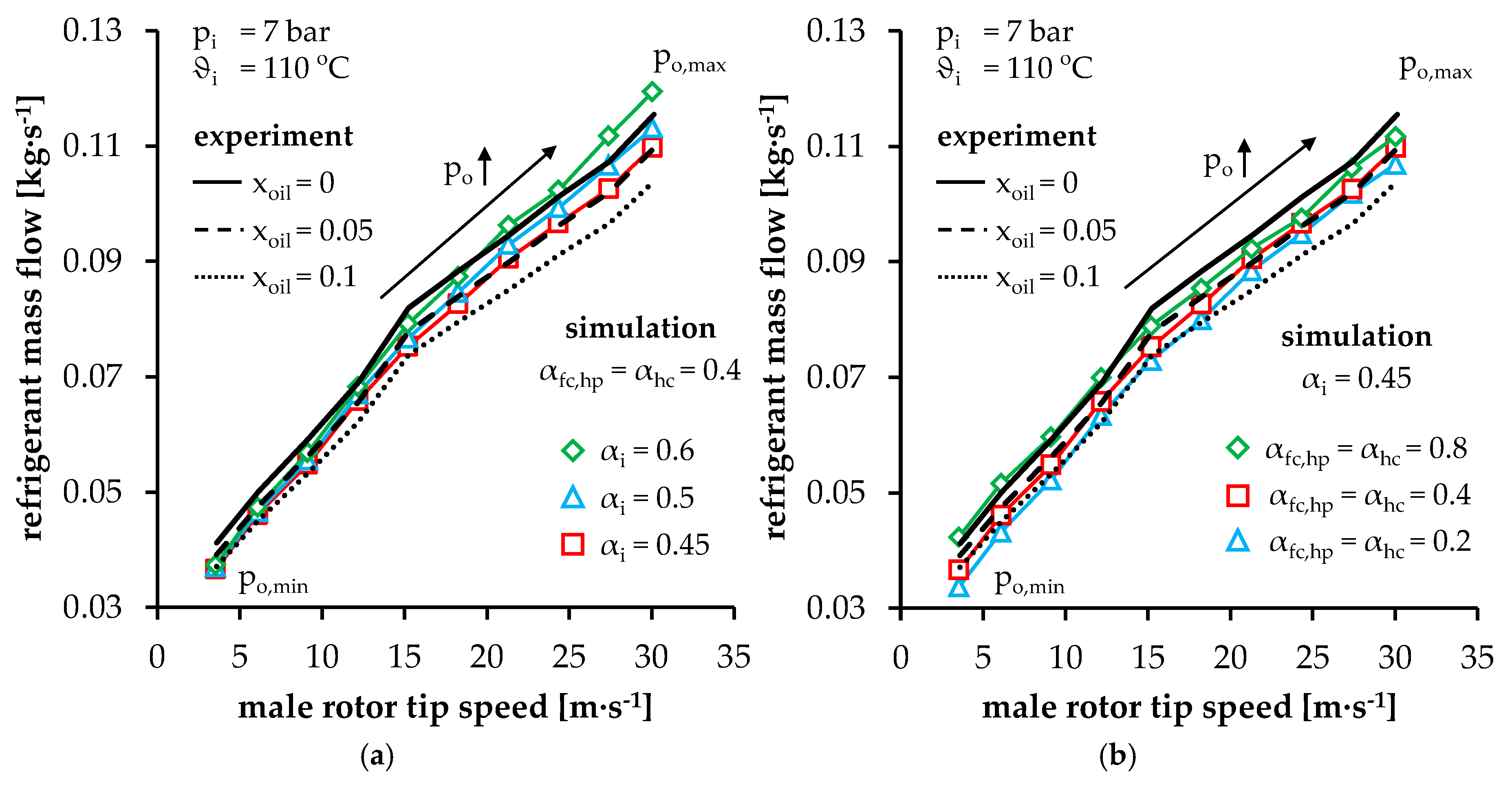
Figure 9.
Simulated and measured refrigerant mass flow at inlet temperatures of 110 °C (a) and 130 °C (b) as a function of the male rotor tip speed at a constant inlet pressure of 7 bar and variable outlet pressure.
Figure 9.
Simulated and measured refrigerant mass flow at inlet temperatures of 110 °C (a) and 130 °C (b) as a function of the male rotor tip speed at a constant inlet pressure of 7 bar and variable outlet pressure.

Figure 10.
Simulated and measured screw expander power at inlet temperatures of 110 °C (a) and 130 °C (b) as a function of the male rotor tip speed at a constant inlet pressure of 7 bar and variable outlet pressure (inlet and clearance flow coefficients correspond to the chamber model calibration in Figure 8 and Figure 9).
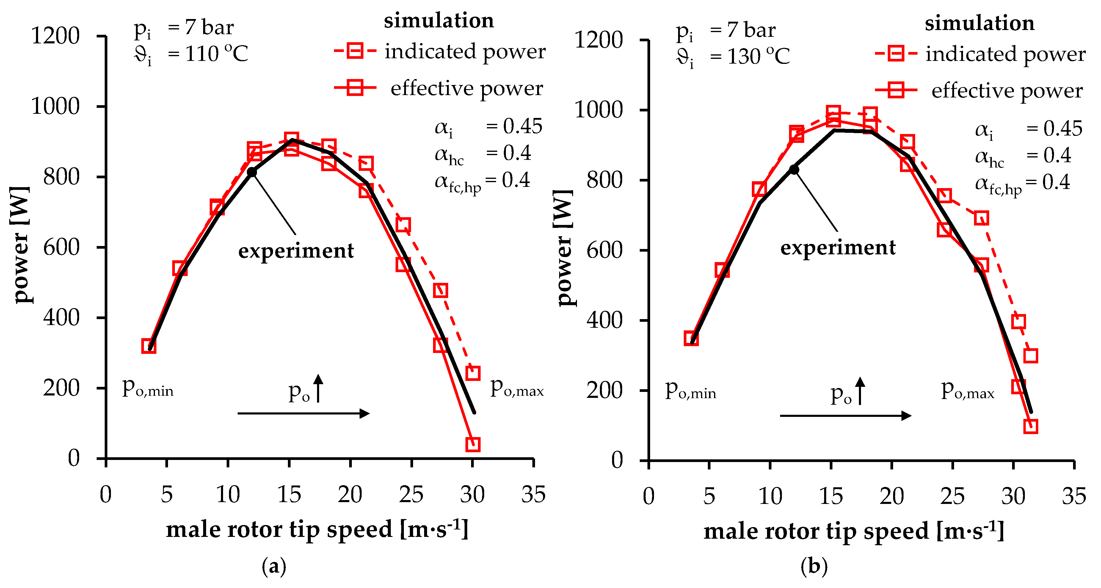
Figure 11.
Simulated and measured refrigerant mass flow (a) and effective power (b) as a function of male rotor tip speed at a constant inlet temperature of 130 °C and variable inlet pressure
Figure 11.
Simulated and measured refrigerant mass flow (a) and effective power (b) as a function of male rotor tip speed at a constant inlet temperature of 130 °C and variable inlet pressure

Figure 12.
Simulated mass flow (a) and delivery rate (b) of SE 34.5 as a function of male rotor tip speed at different inlet pressure and temperature levels and a constant back-pressure of 2 bar.
Figure 12.
Simulated mass flow (a) and delivery rate (b) of SE 34.5 as a function of male rotor tip speed at different inlet pressure and temperature levels and a constant back-pressure of 2 bar.
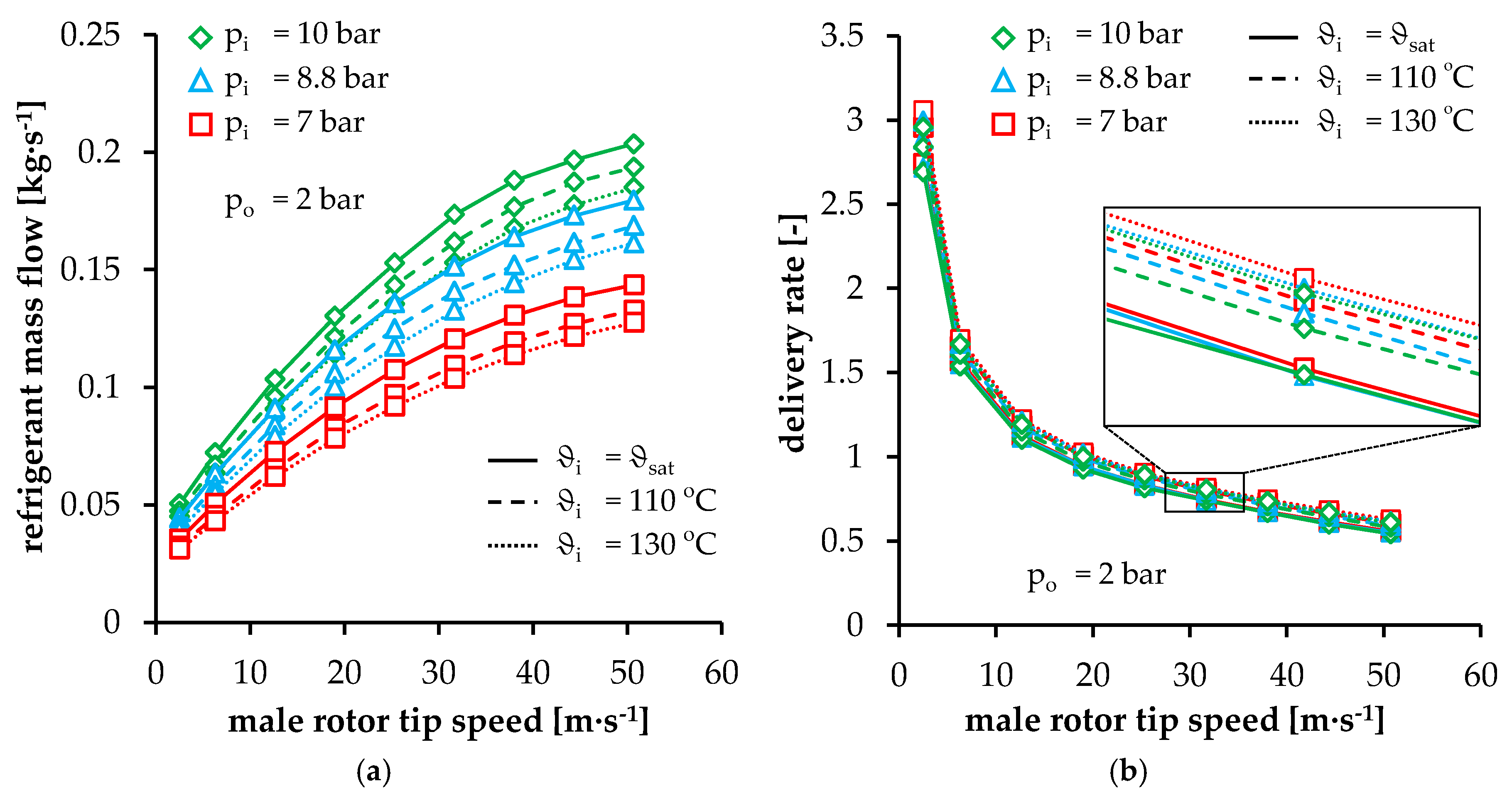
Figure 13.
Simulated indicated and effective power of SE 34.5 at an inlet pressure of 7 bar and saturation temperature, depending on male rotor tip speed and back-pressure (a); effective power as a function of male rotor tip speed at different inlet pressure and temperature levels and a constant back-pressure of 2 bar (b).

Figure 14.
Simulated working chamber pressure depending on the male rotor angular position at a constant tip speed of 2.5 m·s−1 (1000 min−1) (a) and 50.7 m·s−1 (20,000 min−1) (b) at an inlet pressure of 7 bar and a back-pressure of 2 bar ( = and = 130°C)
Figure 14.
Simulated working chamber pressure depending on the male rotor angular position at a constant tip speed of 2.5 m·s−1 (1000 min−1) (a) and 50.7 m·s−1 (20,000 min−1) (b) at an inlet pressure of 7 bar and a back-pressure of 2 bar ( = and = 130°C)
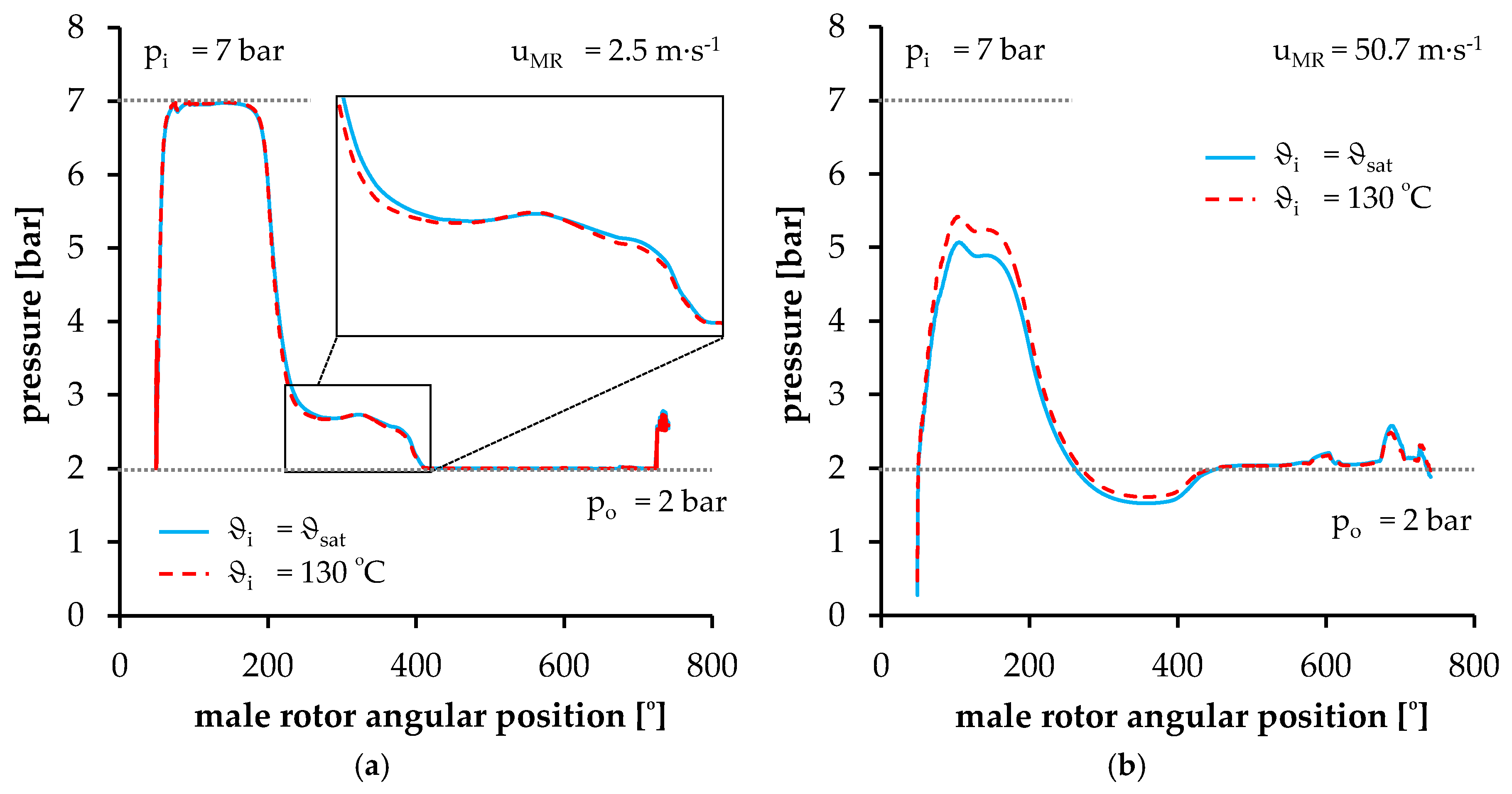
Figure 15.
Simulated indicated isentropic efficiency (a) and effective isentropic efficiency (b) depending on male rotor tip speed at different inlet pressure and temperature levels and a constant back-pressure of 2 bar.
Figure 15.
Simulated indicated isentropic efficiency (a) and effective isentropic efficiency (b) depending on male rotor tip speed at different inlet pressure and temperature levels and a constant back-pressure of 2 bar.

Figure 16.
Simulated indicated isentropic efficiency (a) and effective isentropic efficiency (b) depending on pressure ratio at different inlet pressure levels, male rotor tip speeds, and a constant inlet temperature of 130 °C.
Figure 16.
Simulated indicated isentropic efficiency (a) and effective isentropic efficiency (b) depending on pressure ratio at different inlet pressure levels, male rotor tip speeds, and a constant inlet temperature of 130 °C.


Table 1.
Parameters of the test twin-screw expander SE 34.5.
| Designation | Unit | Male Rotor (MR) | Female Rotor (FR) |
|---|---|---|---|
| Rotor profile | [-] | modified asymmetric SRM | |
| Axis-centre distance | [mm] | 34.5 | |
| Built-in volume ratio | [-] | 2.5 | |
| Displaced volume per male rotor rotation | [cm3] | 49.9 | |
| Number of lobes | [-] | 3 | 5 |
| Rotor length | [mm] | 38.8 | 38.8 |
| Diameter | [mm] | 48.4 | 45.5 |
| Wrap angle | [°] | 200 | −120 |
| Rotor lead | [mm] | 69.84 | 116.4 |
| Front clearance height (hp) | [mm] | 0.05 | 0.05 |
| Front clearance height (lp) | [mm] | 0.25 | 0.25 |
| Housing clearance height | [mm] | 0.1 | 0.05 |
Table 2.
Specifications for the oil-lubricated bearings [27] in the test twin-screw expander SE 34.5.
Table 2.
Specifications for the oil-lubricated bearings [27] in the test twin-screw expander SE 34.5.
| Bearing Position | Bearings Per Rotor | Bearing Type | Specific Bearing Parameters |
|---|---|---|---|
| Fixed bearing | 3 | B7002-E-T-P4S | = 2; = 2310 N |
| Floating bearing | 1 | 6002-C | = 1.7; = 2850 N |
Table 3.
Operating parameters for the investigations of SE 34.5 on the ORC test rig with R245fa as working fluid.
Table 3.
Operating parameters for the investigations of SE 34.5 on the ORC test rig with R245fa as working fluid.
| Parameter | Value |
|---|---|
| Working fluid | R245fa |
| Lubricant | Emkarate® RL32-3MAF (VG32) |
| Maximum ORC mass flow | 0.13 kg·s−1 (R245fa + lubricant) |
| Inlet pressure (absolute) | 7 bar, 8.8 bar, and 10 bar |
| Outlet pressure (absolute) | 1.5–4.4 bar (variable) |
| Inlet temperature | saturation temperature, 110°C, and 130 °C |
Table 4.
Characteristic numbers for the evaluation of the operation of SE 34.5.
| Parameter | Characteristic Number | |
|---|---|---|
| recorded | ||
| simulated with KaSim (see Section 3.3) | ||
| recorded | ||
| calculated (see Section 3.4) | ||
Table 5.
Approach to hydraulic losses according to [19].
Table 5.
Approach to hydraulic losses according to [19].
| Parameter | Calculation Approach | Auxiliary Parameters |
|---|---|---|
| Acceleration losses (oil and refrigerant) | ; ; | |
| Fluid friction losses (oil) | ||
| Impulse losses (oil) | ||
Table 6.
Approach to mechanical loss calculation in bearings according to [27].
Table 6.
Approach to mechanical loss calculation in bearings according to [27].
| Parameter | Calculation Approach | Auxiliary Parameters |
|---|---|---|
| Bearing friction losses | bearing coefficient for speed-dependent frictional torque; average bearing diameter; kinematic oil viscosity; specific bearing coefficient; decisive load for frictional torque (radial/axial); equivalent static bearing load (radial/axial); basic static load | |
| Speed-dependent frictional torque | ||
| Load-dependent frictional torque | ||
| Fixed bearing | ||
| Floating bearing |
Table 7.
Free parameters for the SE 34.5 chamber model calibration.
| Name | Symbol | Range of Variation | |
|---|---|---|---|
| Lubricant mass fraction | 0.05 | ||
| Inlet flow coefficient | 0.45–0.8 | ||
| Outlet flow coefficient | 0.8 | ||
| Clearance flow coefficient | High-pressure front clearances | 0.2–0.8 | |
| Low-pressure front clearances | 0.8 | ||
| Housing clearances | 0.2–0.8 | ||
| Intermesh clearance | 0.8 | ||
| Blow hole | 0.8 | ||
Table 8.
Boundary conditions of characteristic map simulations using R245fa.
| Parameter | Value |
|---|---|
| ORC Parameters | |
| Working fluid | R245fa |
| Oil mass fraction | 0.05 |
| Inlet pressure (saturation temperature) | 7 bar (75.4 °C), 8.8 bar (84.5 °C), 10 bar (89.75 °C) |
| Outlet pressure | 1.5–5 bar (variable) |
| Inlet temperature | saturation temperature, 110 °C, and 130 °C |
| Twin-Screw Expander Parameters | |
| Rotational speed | max. 20,000 min−1 |
| Male rotor tip speed | max. 50.7 m·s−1 |
| Flow coefficients | |
| Inlet | 0.45 |
| Outlet | 0.8 |
| High-pressure front clearance (MR and FR) | 0.4 |
| Low-pressure front clearance (MR and FR) | 0.8 |
| Housing clearance (MR and FR) | 0.4 |
| Intermesh clearance | 0.8 |
| Blow hole | 0.8 |
| Clearance heights (MR and FR) | |
| High-pressure front clearance | 0.05 mm |
| Low-pressure front clearance | 0.25 mm |
| Housing clearance | 0.05 mm |
© 2017 by the authors. Licensee MDPI, Basel, Switzerland. This article is an open access article distributed under the terms and conditions of the Creative Commons Attribution (CC BY) license (http://creativecommons.org/licenses/by/4.0/).
Share and Cite
MDPI and ACS Style
Nikolov, A.; Brümmer, A. Investigating a Small Oil-Flooded Twin-Screw Expander for Waste-Heat Utilisation in Organic Rankine Cycle Systems. Energies 2017, 10, 869. https://doi.org/10.3390/en10070869
AMA Style
Nikolov A, Brümmer A. Investigating a Small Oil-Flooded Twin-Screw Expander for Waste-Heat Utilisation in Organic Rankine Cycle Systems. Energies. 2017; 10(7):869. https://doi.org/10.3390/en10070869
Chicago/Turabian StyleNikolov, Alexander, and Andreas Brümmer. 2017. "Investigating a Small Oil-Flooded Twin-Screw Expander for Waste-Heat Utilisation in Organic Rankine Cycle Systems" Energies 10, no. 7: 869. https://doi.org/10.3390/en10070869
Note that from the first issue of 2016, this journal uses article numbers instead of page numbers. See further details here.