Efficiency of Recycling Double-Pass V-Corrugated Solar Air Collectors

Energy and Opto-Electronic Materials Research Center, Department of Chemical and Materials Engineering, Tamkang University, Tamsui, New Taipei 251, Taiwan
*
Author to whom correspondence should be addressed.
Energies 2017, 10(7), 875; https://doi.org/10.3390/en10070875
Submission received: 31 May 2017
/
Accepted: 26 June 2017
/
Published: 29 June 2017
(This article belongs to the Section D: Energy Storage and Application)
Abstract
:The influence of recycling on double-pass solar air collectors with welding of the V-corrugated absorber has been studied experimentally and theoretically. Welding the V-corrugated absorber and the recycle-effect concept to the solar air collector was proposed to strengthen the convective heat-transfer coefficient due to turbulence promotion. Both the recycle effect and the V-corrugated absorber can effectively enhance the heat transfer efficiency compared to various designs such as single-pass, flat-plate double-pass, and double-pass wire mesh packed devices. Recycling operations and welding the V-corrugated absorber could enhance the collector efficiency by increasing the recycle ratio, incident solar radiations, and air mass flow rates. The most efficient and economical operating conditions were found at R ≈ 0.5, with relatively small hydraulic dissipated energy compensation. It was found that the turbulence intensity increase from welding the V-corrugated absorber into the solar air collector channel could compensate for the power consumption increase, when considering economic feasibility.
1. Introduction
New designs of solar air collectors with welding of the V-corrugated absorber into double-pass devices under recycling operations has been proposed and studied, as shown in Figure 1a,b. The experimental setup was fabricated with the V-shape corrugated absorber welded on the flat-plate solar air collector to validate the theoretical predictions calculated by mathematical modeling. A higher device performance was obtained with a recycling double-pass V-corrugated collector than with a flat-plate solar air collector of the same working dimensions. El-Sebaii and Shalaby [1] and Sevik [2] discussed the design and experimental investigation of solar dryers. Razika, et al. [3] and Al-Kayiem, Yassen [4] studied the inclination angel for the absorption–convection heat transfer behavior in a solar air collector. El-Sebaii and Al-Snani [5] investigated the effects of various selective coating materials on the collector’s performance. Improvement of solar collector efficiency in many devices has been investigated by introducing free convection [6] and force convection [7], extending heat transfer area [8], and increasing flow turbulence in a solar air heater channel with vortex generators [9,10] and welding V-ribs [11]. The application of the recycle effect concept to solar air heaters has been confirmed with technical feasibility in double-pass [12] and multi-pass [13] operations, and the recycling double-pass design with eddy promotion [14,15] results in enhancement of the convective heat-transfer coefficient. The new designs in the present study of solar air collectors were investigated, adopting the V-corrugated recycling double-pass device to increase the convective heat-transfer coefficients due to both the enhancement of flow turbulence and enlargement of the heat-transfer area, as shown in Figure 1a,b, respectively.
The purposes of the present study are: (a) to carry out theoretical predictions and experimental runs of operating the recycling double-pass V-corrugated solar air collector; (b) to investigate the influences of the recycle ratio and air mass flow rate on the heat-transfer efficiency enhancement and power consumption; (c) to investigate the economic feasibility of the new design of the recycling double-pass V-corrugated solar air collectors.
2. Theoretical Analysis
Consider the heat transfer in two subchannels with welding of the V-corrugated absorber plate to divide a parallel conduit of height , length and width , as shown in Figure 1a,b with the different air flow arrangements. Before entering the lower subchannel (flow pattern A), as shown in Figure 1a, the inlet air mass flow rate and inlet temperature is premixed with the recycling air flow exiting from the upper subchannel with the outlet temperature . The inlet air mass may flow through the upper channel firstly (flow pattern B), as shown in Figure 1b.
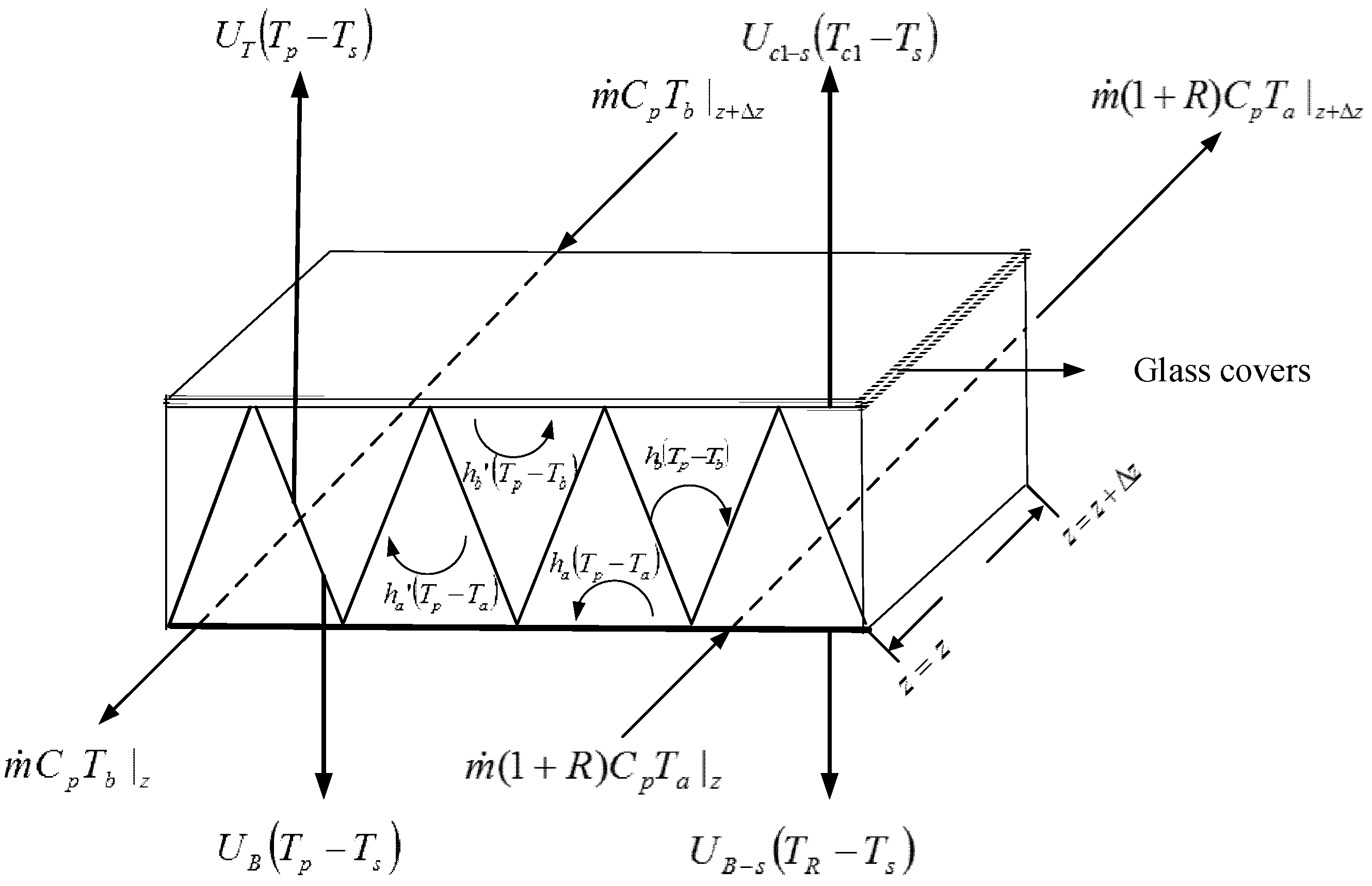
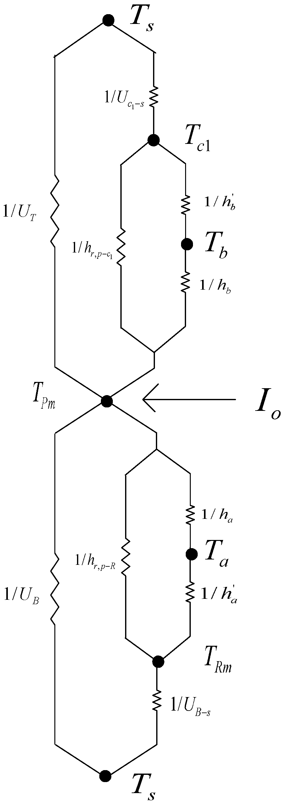
By following the same mathematical treatment and experimental methods performed in our previous work [16], except welding the V-corrugated absorber instead of packing wire mesh, the theoretical solutions of the temperature distributions of the flowing air in the lower and upper subchannels were obtained, making the energy balance on a finite system element, as shown in Figure 2. The various heat transfer coefficients at different components of the solar air heater were sketched in the thermal resistance network in Figure 3. The results are:
The definitions of , , , , , , and are referred to in the Appendix A. In obtaining the above results for the steady-state one-dimensional mathematical formulation, the boundary conditions are:
The outlet temperature of can be calculated from Equation (1).
The useful energy gained by the flowing air was estimated from the energy balance on the lower subchannel, upper subchannel, and whole solar air collector with the known inlet and outlet temperatures, respectively.
The collector efficiency of the recycling double-pass V-corrugated solar air collector was obtained from the actual useful energy gained by the airflow and the incident solar radiation as:
The average absorber temperature was readily obtained, equating the terms of Equation (7) as:
3. Experimental Setup
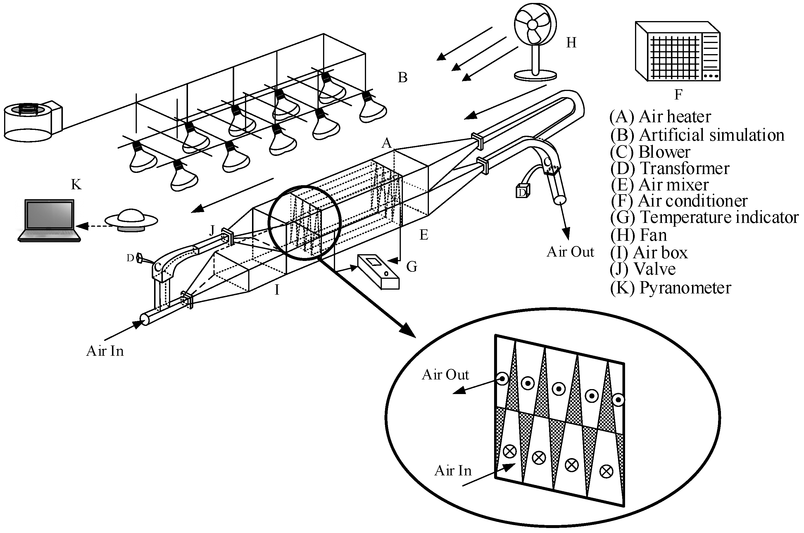
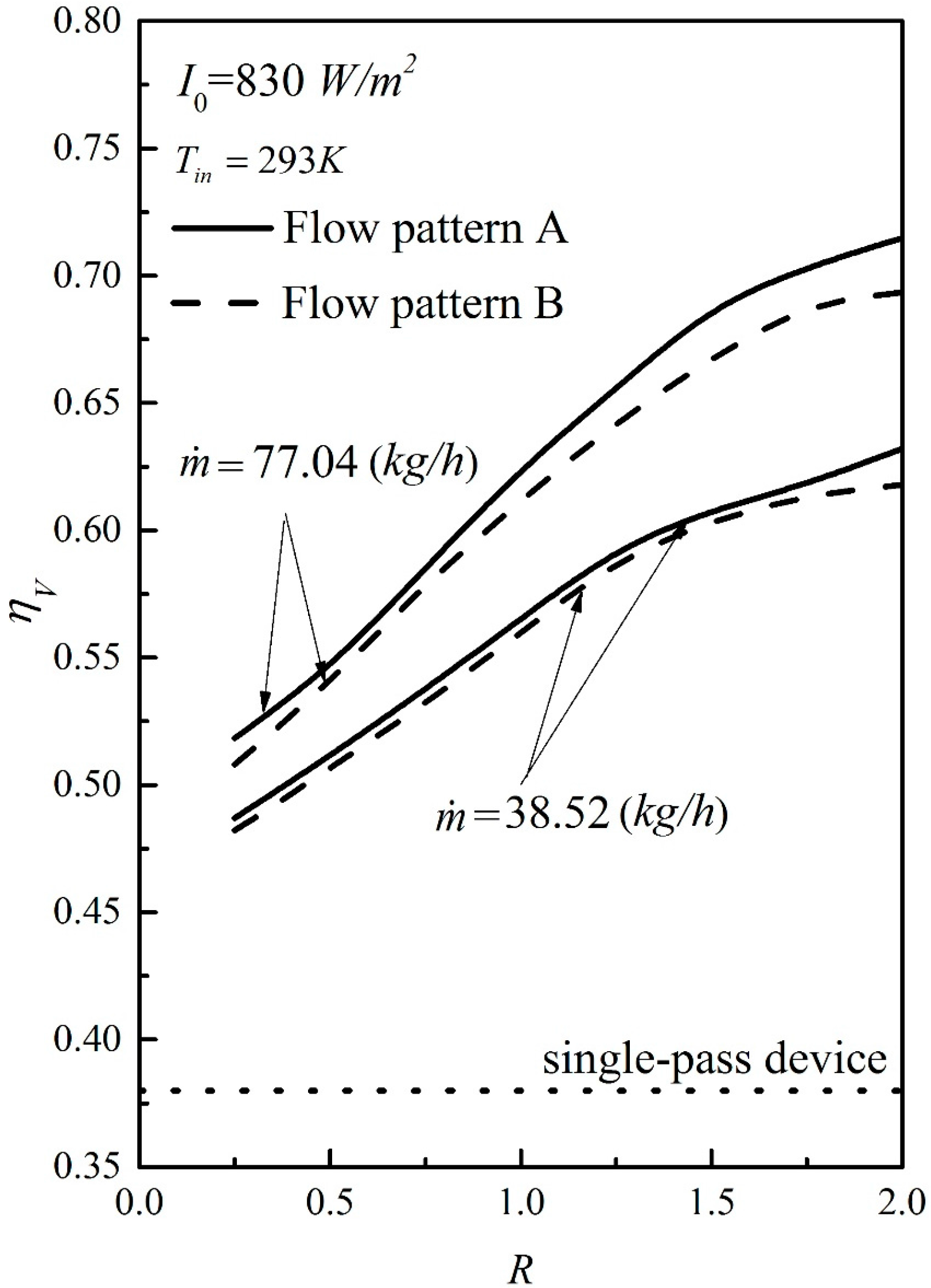
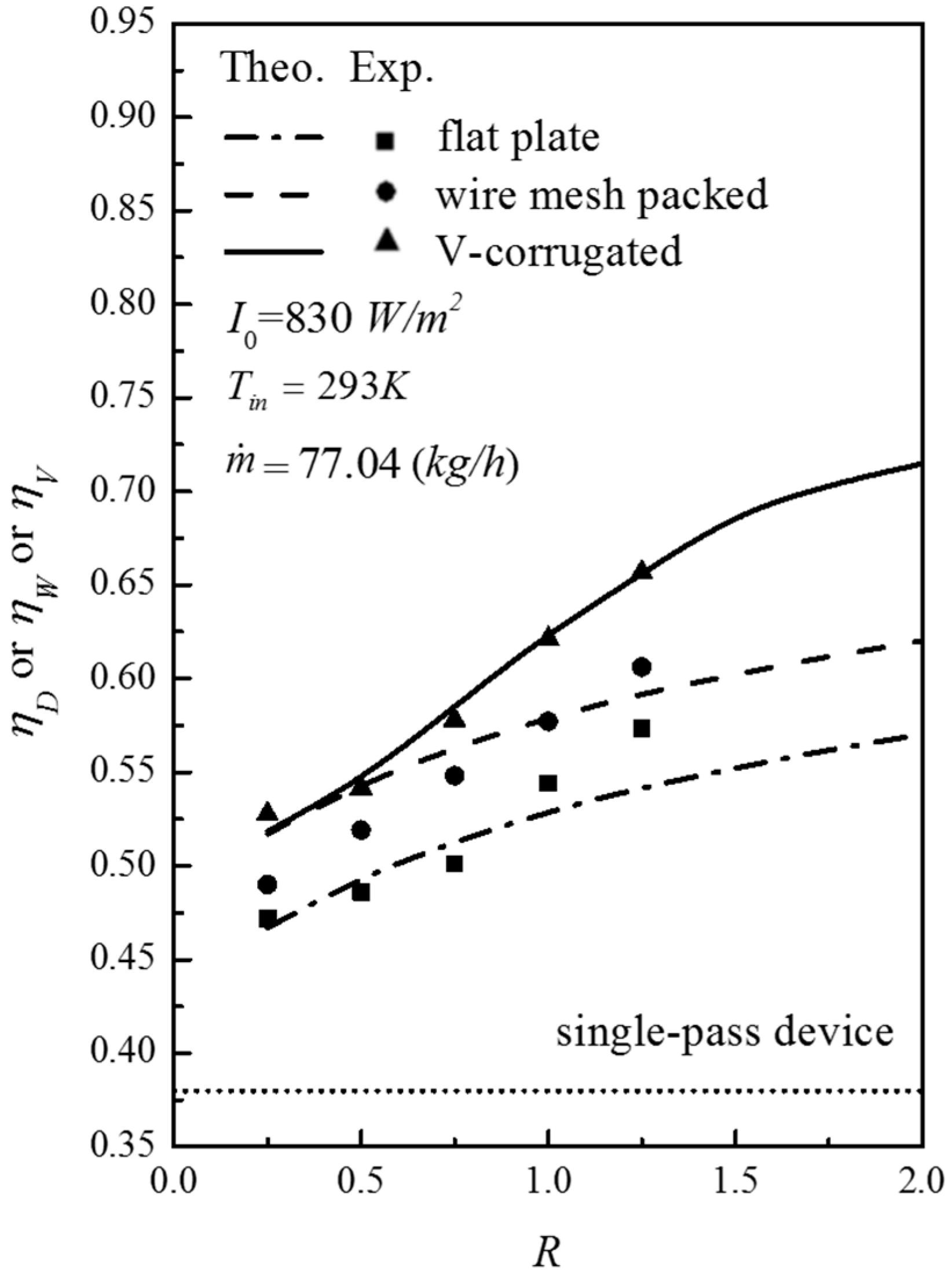
The recycling double-pass solar air collectors are welded to four units of V-shape stainless steel absorbing plate of 7 × 10⁻⁵ m thickness on the bottom plate to divide the air flow conduit of width W, length L, and height Hg into two subchannels, as shown in Figure 4 (flow pattern A). A photo of the experimental device was taken and shown in Figure 5. Three configurations of solar air collectors, such as the downward single-pass device, recycling double-pass wire mesh, and recycling double-pass V-corrugated absorber were investigated theoretically and experimentally. The experimental runs were conducted using a blower (Teco 3 Phase Induction Motor, Model BL model 552, Redmond Co, Owosso, MI, USA) to supply the ambient air, and the air mass flow rate was measured using an anemometer (Kanmax Japan Inc., Osaka, Japan). The device parameters [17] and operating conditions are as follows: L = W = 0.3 m; Hg = 0.062 m; ks = 46.64 W/m·K; = 0.875; = 0.95; = 0.94; = 0.8; = 0.94; = 830 and 1100 W/m2; = 293,303 and 313 K; = 1.0 m/s; = 0.0107, 0.0161 and 0.0214 kg/s; = 293 K, σ = 5.68 × 10⁻⁸ W/m2·K4. The calculation methods for flow pattern B are similar to those in the previous section of flow pattern A. A comparison of both flow patterns in Figure 6 indicates a greater collector performance improvement in operating flow pattern A is higher than that in the flow pattern B. Therefore, all the theoretical predictions and experimental works were carried out using flow pattern A as an illustration in the present study. The evaluation procedure for collector efficiency is now described. With known device geometries (W, L, Hg), physical properties (ks, , , , , , , , ) and the given operating conditions (, , , , ), a temporary is first estimated from Equation (7) using Equation (8a) for calculating once is assumed. The value is thus re-checked using Equation (8b) by continued iterations, and the final value was obtained until the last value meets the required convergence. The theoretical predictions were obtained by substituting the specified values of physical properties and operation conditions into the appropriate equations, and the results are represented in Figure 7 and Figure 8 for comparison. The influence of the recycle ratio on collector efficiencies of theoretical predictions and experimental results for various incident solar radiations, recycle ratios, and air mass flow rates are presented in Figure 7 and Figure 8, respectively.
Moffat [18] determined the experimental uncertainty of each individual measurement directly from the experimental run as follows:
and the mean value of the resulting experimental uncertainty was defined by:
Estimations of the experimental uncertainty for = 830 and = 1100 W/m2 with three air mass flow rates were calculated. The mean experimental uncertainty of the measurements in Figure 7 and Figure 8 ranged between 2.60 × 10⁻³ ≤ ≤ 7.46 × 10⁻³. Meanwhile, the difference of the experimental results from the theoretical predictions may be defined as:
Difference deviations between the theoretical and experimental values were quantified and calculated using Equation (11) within 0.13 ≤ ≤ 2.85 under two solar radiation incidents for two configurations without (flat-plate type) and with attaching wire mesh. A fairly good agreement between theoretical predictions and experimental runs was achieved.
4. Collector Efficiency Improvement
By following the same mathematical treatment and experimental methods performed in our previous work [16], except welding the V-corrugated absorber instead of packing with wire mesh, the device performance improvements of the three types of recycling double-pass devices, namely flat-plate, wire mesh, and V-corrugated devices, were defined as the improvement of each collector’s efficiency, , and , as defined by Equations (12)–(14), respectively, relative to that of the downward-type single-pass device of the same working dimensions, as follows:
in which , , and denote collector efficiencies of the double-pass flat-plate device, multi-pass flat-plate device, the baffled device with fins attached, the downward-type single-pass device, and the V-corrugated device, respectively. The present work is actually the extension of previous work [16], except with welding of the V-corrugated absorber. The collector efficiencies of , and were investigated in our previous work [16] and the collector efficiency improvements of , and for the devices of the flat-plate, wire mesh, and V-corrugated absorbers were calculated in Equations (12)–(14), respectively, for comparison.
5. Results and Discussion
The calculation methods and procedures were performed exactly the same as those of our previous work [16], and thus, the results will be discussed. All the theoretical predictions and experimental results of , and increase with the recycle ratio and incident solar radiations, as seen from Figure 7 and Figure 8.
It is indicated from Figure 7 and Figure 8 that the collector efficiency of the V-corrugated solar air collector is higher than those of the flat-plate and wire mesh devices. The collector efficiency increase with recycle ratio and air mass flow rate, especially for the V-corrugated device when operating at the higher recycle ratio, as confirmed by Table 1. Restated, the collector efficiency increases with increasing recycle ratios and air mass flow rates due to a higher convective heat-transfer coefficient being achieved. Furthermore, Figure 9 gives a graphical representation of the collector performance improvements of , , and for the flat-plate, wire mesh packed, and V-corrugated double-pass devices under the same operating conditions, respectively. The collector performance improvement decreases with the air mass flow rate to a more remarkable extent, while the improvement increases with the recycle ratio, as shown in Figure 9 and Table 1 as well. However, the collector efficiency improvement of the V-corrugated solar air collector is better than other recycling configurations such as flat-plate and wire mesh packed solar air collectors for all mass flow rates and recycle ratios. Moreover, the hydraulic dissipated energy and power consumption increases owing to recycling double-pass operation with the V-corrugated absorber are defined as:
double-pass V-corrugated device.
for V-corrugated device [19], i = a, b.
The power consumption increase for the double-pass V-corrugated devices is defined relative to that in the downward single-pass operation as:
the V-corrugated device.
Similarly, for the flat-plate device and wire mesh packed device:
the flat-plate device.
the wire mesh packed device.
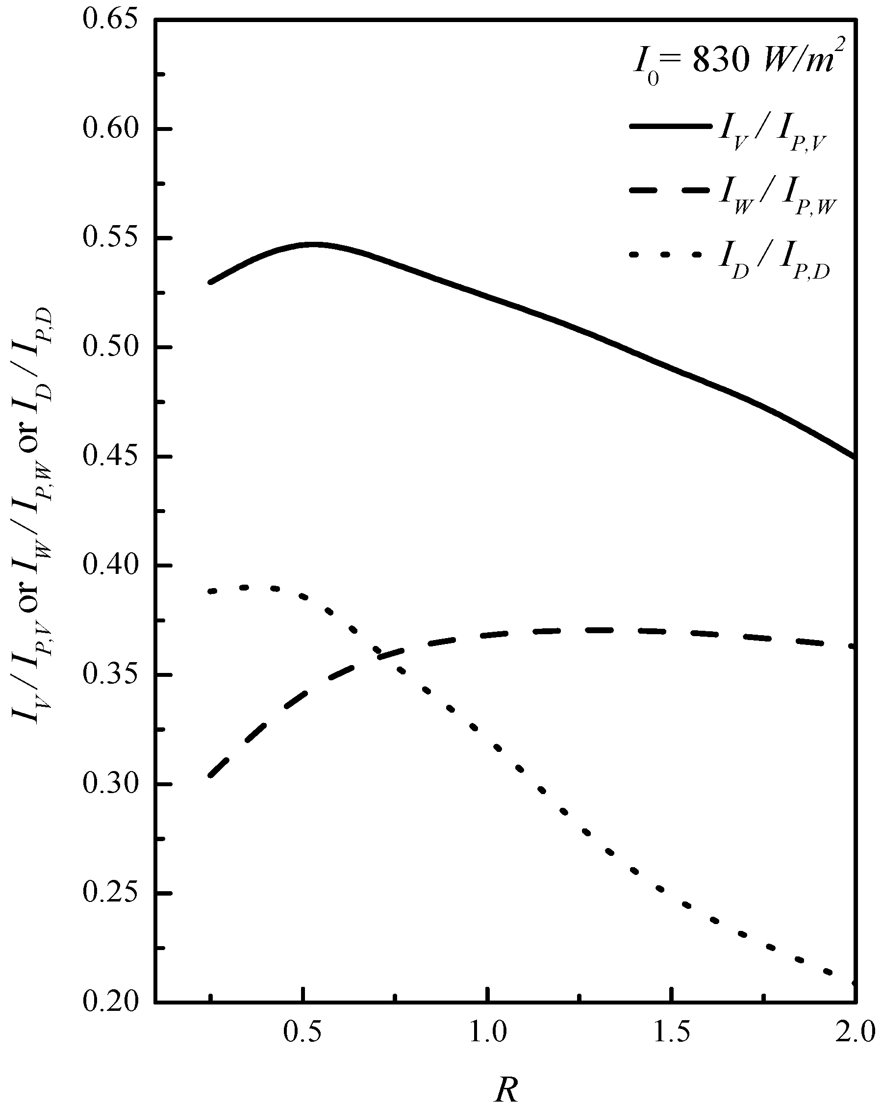
The effects of various recycle ratios and air mass flow rates on the ratio of both the efficiency improvement and the power consumption, , and for various configurations were calculated and presented for comparison and for making an economic judgement to demonstrate feasible operating conditions. The higher value of is obtained in operating recycling double-pass V-corrugated solar air collectors, as demonstrated in Figure 10. The extent of collector efficiency improvement is more notable with recycle ratio for the recycling double-pass V-corrugated solar air collectors than for the flat-plate and wire mesh packed devices. With this comparison, the advantage of the present design is evident.
6. Conclusions
The strategies for improving the performance of recycling double-pass V-corrugated solar air collectors are either the preheating effect or enhancing the convective heat-transfer coefficient. The improvement of collector efficiency in such devices with welding of the V-corrugated absorber has been investigated analytically and experimentally. The introduction of external recycling creates a positive effect on the heat transfer, which provides better collector efficiency due to the enhanced convective heat-transfer coefficient. This is caused by an increase in the turbulence of air flowing above and under the V-corrugated absorber. The improvement in device performance is obtainable by using a recycling double-pass V-corrugated device rather than without recycling or by using flat-plate devices, as indicated in Figure 7 and Figure 8. Moreover, the ratio of , alongside recycle ratio and air mass flow rate, were represented in Figure 10 to investigate the optimal operation conditions for considering the economic feasibility of various double-pass configurations. The present findings can be summarized as follows: (1) Application of the recycling double-pass V-corrugated solar air collector is technically and economically feasible as compared to both of the flat-plate and wire mesh packed solar air collectors; (2) Collector performance increases with increasing the recycle ratio but with decreasing the air mass flow rate, and with the inlet air flowing through the lower channel first (flow pattern A), device performance is higher than that in the device with the inlet air flowing through the upper channel first (flow pattern B); (3) The optimal recycle ratio for both economic and technical operation, with relatively small compensation for increased hydraulic dissipated energy, was found to be R ≈ 0.5; (4) The advantage of the present device is evident, and the present study provides an important contribution to solar air collectors by coupling external recycling and different geometric designs of absorbing plates.
Acknowledgment
The authors wish to thank the Ministry of Science and Technology of the Republic of China for the financial support.
Author Contributions
This paper is a result of the full collaboration of all the authors. However, the concept for this research was conceived by Chii-Dong Ho, Ching-Fang Hsiao contributed to mathematical derivations, Hsuan Chang and Zih-Syuan Hong elaborated the manuscript preparation, and Yi-En Tien performed the experiments.
Conflicts of Interest
The authors declare no conflict of interest.
Nomenclature
| Surface area of the collector = LW (m2) | |
| Bi | Coefficients defined in Equations (A1)–(A6) |
| Ci | Coefficients defined in Equations (A16) and (A17) |
| Specific heat of air at constant pressure (J/(kg K)) | |
| Equivalent diameter of downward-type single-pass device (m) | |
| Equivalent diameter of lower subchannel of double-pass device (m) | |
| Equivalent diameter of upper subchannel of double-pass device (m) | |
| Deviation of the experimental measurements from theoretical predictions, defined in Equation (11) | |
| Fi | Coefficients defined in Equations (A18)–(A20) |
| Fanning friction factor | |
| Coefficients defined in Equations (A7)–(A13) | |
| Hg | Height of channels (m) |
| ha | Convection coefficient between the absorber plate and subchannel a (W/(m2 K)) |
| hb | Convection coefficient between the absorber plate and subchannel b (W/(m2 K)) |
| Radiation heat transfer coefficient between cover 1 and absorber plate (W/m2 K) | |
| Radiation heat transfer coefficient between absorber plate and bottom plate (W/m2 K) | |
| hw | Convective heat transfer coefficient for air flowing over the outside surface of glass cover (W/(m2 K)) |
| Incident solar radiation (W/m2) | |
| Percentage of collector efficiency improvement, defined in Equation (12) | |
| Power consumption increment, defined in Equations (20)–(22) | |
| Percentage of collector efficiency improvement, defined in Equation (13) | |
| Percentage of collector efficiency improvement, defined in Equation (14) | |
| ks | Thermal conductivity of insulator (W/(m K)) |
| Channel length (m) | |
| ls | Thickness of insulator (m) |
| Lower subchannel friction loss of double-pass device (J/kg) | |
| Upper subchannel friction loss of double-pass device (J/kg) | |
| Friction loss of downward-type single-pass device (J/kg) | |
| Total air mass flow rate (kg/h) | |
| N | Number of glass cover |
| Number of experimental measurements | |
| Nu | Nusselt number |
| PD | Power consumption of the flat plate double-pass device (W) |
| PS | Power consumption of downward-type single-pass device (W) |
| PV | Power consumption of the V corrugated double-pass device (W) |
| PW | Power consumption of the wire mesh packed double-pass device (W) |
| Useful energy gained by air (W) | |
| R | Recycle ratio, reverse air mass flow rate divided by input air mass flow rate |
| The experimental uncertainty of an individual measurement | |
| The mean value of | |
| Re | Reynolds number |
| Inlet air temperature (K) | |
| The mixing temperature of the subchannel a at x = 0 (K) | |
| The temperature of the subchannel a at x = L (K) | |
| The temperature of the subchannel b at x = 0 (K) | |
| The temperature of the subchannel b at x = L (K) | |
| Axial fluid temperature distribution in subchannel a (K) | |
| Axial fluid temperature distribution in subchannel b (K) | |
| Temperature of glass cover 1 (K) | |
| Temperature of absorbing plate (K) | |
| Mean temperature of absorbing plate (K) | |
| Ambient temperature (K) | |
| Loss coefficient from the bottom of solar air heater to the ambient environment (W/(m2 K)) | |
| Loss coefficient from the surfaces of edges and the bottom of the solar collector to the ambient environment (W/m2 K) | |
| Loss coefficient from the inner cover to the ambient environment (W/m2 K) | |
| Loss coefficient from the top of solar air heater to the ambient environment (W/m2 K) | |
| W | Width of both upper and lower subchannels (m) |
| Mean air velocity in the downward-type single-pass device (m/s) | |
| Mean air velocity in subchannel a of double-pass device (m/s) | |
| Mean air velocity in subchannel b of double-pass device (m/s) | |
| Yi | Coefficients defined in Equations (A14) and (A15) |
| Axial coordinate (m) | |
| Greek Letters | |
| Absorptivity of the absorbing plate | |
| Collector efficiency of the flat-plate double-pass device | |
| Collector efficiency of the downward type single-pass device | |
| Collector efficiency of the double-pass V-corrugated solar air ter | |
| Collector efficiency of the double-pass wire mesh packed solar air heater | |
| Experimental data of collector efficiency | |
| The mean value of the experimental data | |
| Theoretical prediction of collector efficiency | |
| Air viscosity (kg/ms) | |
| Transmittance of glass cover | |
| Emissivity of glass cover | |
| Emissivity of absorbing plate | |
| Air density (kg/m3) | |
| Dimensionless channel length | |
Appendix A
References
- El-Sebaii, A.A.; Shalaby, S.M. Experimental investigation of an indirect-mode forced convection solar dryer for drying thymus and mint. Energy Convers. Manag. 2013, 74, 109–116. [Google Scholar] [CrossRef]
- Sevik, S. Design, experimental investigation and analysis of a solar drying system. Energy Convers. Manag. 2013, 8, 27–34. [Google Scholar]
- Razika, I.; Nabila, I.; Madani, B.; Zohra, H.F. The effects of volumetric flow rate and inclination angle on the performance of a solar thermal collector. Energy Convers. Manag. 2014, 78, 931–937. [Google Scholar] [CrossRef]
- Al-Kayiem, H.H.; Yassen, T.A. On the natural convection heat transfer in a rectangular passage solar air heater. Sol. Energy 2015, 12, 10–18. [Google Scholar] [CrossRef]
- El-Sebaii, A.A.; Al-Snani, H. Effect of selective coating on thermal performance of flat plate solar air heaters. Energy 2010, 35, 1820–1828. [Google Scholar] [CrossRef]
- Vaziri, R.; Ilkan, M.; Egelioglu, F. Experimental performance of performance of perforated glazed solar air heaters and unglazed transpired solar air heater. Sol. Energy 2015, 119, 251–260. [Google Scholar] [CrossRef]
- Sharma, K.S.; kalamkar, V.R. Experimental and numerical investigation of forced convection heat transfer in solar air heater with thin ribs. Sol. Energy 2017, 147, 227–291. [Google Scholar] [CrossRef]
- Fudholi, A.; Sopian, K.; Othman, M.Y.; Ruslan, M.H.; Bakhtyar, B. Energy analysis and improvement potential of finned double-pass solar collector. Energy Convers. Manag. 2013, 75, 234–240. [Google Scholar] [CrossRef]
- Tamna, S.; Skullong, S.; Thianpong, C.; Promvonge, P. Heat transfer behaviors in a solar air heater channel with multiple V-baffle vortex generators. Sol. Energy 2014, 110, 720–735. [Google Scholar] [CrossRef]
- Skullong, S.; Promvonge, P.; Thianpong, C.; Pimsarn, M. Thermal performance in solar air heater channel with combined wavy-groove and perforated-delta wing vortex generators. Sol. Appl. Therm. Eng. 2016, 100, 611–620. [Google Scholar] [CrossRef]
- Maithani, R.; Saini, J.S. Heat transfer and friction factor correlations for a solar air heater duct roughened artificially with V-ribs with symmetrical gaps. Exp. Therm. Fluid Sci. 2016, 70, 220–227. [Google Scholar] [CrossRef]
- El-Sebaii, A.A.; Aboul-Enein, S.; Ramadan, M.R.I.; Shalaby, S.M.; Moharram, B.M. Investigation of thermal performance of double-pass flat and v-corrugated plate solar air heaters. Energy 2011, 36, 1076–1086. [Google Scholar] [CrossRef]
- Garg, H.P.; Sharma, V.K.; Bhargava, A.K. Theory of multiple-pass solar air heaters. Energy 1985, 10, 589–599. [Google Scholar] [CrossRef]
- Wijeysundera, N.E.; Ah, L.L.; Tjioe, L.E. Thermal performance study of two-pass solar air heaters. Sol. Energy 1982, 28, 363–370. [Google Scholar] [CrossRef]
- Singh, S.; Dhiman, P. Thermal and thermohydraulic performance evaluation of a novel type double pass packed bed solar air heater under external recycle using an analytical and RSM (response surface methodology) combined approach. Energy 2014, 72, 344–359. [Google Scholar] [CrossRef]
- Ho, C.D.; Lin, C.S.; Chuang, Y.C.; Chao, C.C. Performance improvement of wire mesh packed double-pass solar air heaters with external recycle. Renew. Energy 2013, 57, 479–489. [Google Scholar] [CrossRef]
- Gupta, M.K.; Kaushik, S.C. Performance evaluation of solar air heater for various artificial roughness geometries based on energy, effective and energy efficiencies. Renew. Energy 2009, 34, 465–476. [Google Scholar] [CrossRef]
- Moffat, R.J. Describing the uncertainties in experimental results. Exp. Therm. Fluid Sci. 1988, 1, 3–17. [Google Scholar] [CrossRef]
- Verma, R.; Chandra, R.; Garg, H.P. Optimization of solar air heaters of different designs. Renew. Energy 1992, 2, 521–531. [Google Scholar] [CrossRef]
Figure 1.
Configuration of recycling double-pass V-corrugated solar air collectors.

Figure 2.
The energy balance in a finite system element (flow pattern A).

Figure 3.
Schematic diagram of V-corrugated solar air heaters as a thermal network.

Figure 4.
Schematic of a recycling double-pass V-corrugated solar air heater (flow pattern A).

Figure 5.
A photo of the experimental device.
Figure 6.
Collector efficiencies of both flow patterns (I0 = 830 W/m2).

Figure 7.
Effect of recycle ratio on collector efficiency (I0 = 830 W/m2).

Figure 8.
Effect of recycle ratio on collector efficiency (I0 = 1100 W/m2).
Figure 9.
Comparisons of collector efficiency between the present device and the previous work [16].
Figure 9.
Comparisons of collector efficiency between the present device and the previous work [16].
Figure 10.
The ratio of vs. recycle ratio R for various configurations.


Table 1.
Theoretical predictions of heat-transfer efficiency improvements in a V-corrugated device of and for = 830 W/m2 and = 1100 W/m2.
Table 1.
Theoretical predictions of heat-transfer efficiency improvements in a V-corrugated device of and for = 830 W/m2 and = 1100 W/m2.
| Mass Flow Rate | Recycle Ratio | I0 = 830 (W/m2) | I0 = 1100 (W/m2) | ||
|---|---|---|---|---|---|
| m (kg/h) | R | ||||
| 38.52 | 0.25 | 0.487 | 57.60 | 0.510 | 69.51 |
| 0.5 | 0.511 | 65.52 | 0.535 | 77.85 | |
| 0.75 | 0.538 | 73.99 | 0.563 | 86.88 | |
| 1 | 0.565 | 82.89 | 0.592 | 96.58 | |
| 1.25 | 0.593 | 91.86 | 0.623 | 106.87 | |
| 1.5 | 0.608 | 96.79 | 0.655 | 117.45 | |
| 1.75 | 0.618 | 99.97 | 0.685 | 127.48 | |
| 2 | 0.632 | 104.58 | 0.704 | 134.01 | |
| 57.96 | 0.25 | 0.503 | 35.98 | 0.530 | 45.62 |
| 0.5 | 0.526 | 42.07 | 0.553 | 52.01 | |
| 0.75 | 0.565 | 52.76 | 0.578 | 58.86 | |
| 1 | 0.597 | 61.34 | 0.622 | 70.99 | |
| 1.25 | 0.630 | 70.32 | 0.658 | 80.84 | |
| 1.5 | 0.663 | 79.15 | 0.697 | 91.55 | |
| 1.75 | 0.676 | 82.65 | 0.744 | 104.32 | |
| 2 | 0.688 | 85.97 | 0.766 | 110.40 | |
| 77.04 | 0.25 | 0.508 | 21.94 | 0.508 | 29.34 |
| 0.5 | 0.536 | 28.46 | 0.536 | 36.06 | |
| 0.75 | 0.580 | 39.11 | 0.580 | 43.41 | |
| 1 | 0.614 | 47.29 | 0.614 | 55.44 | |
| 1.25 | 0.651 | 56.04 | 0.651 | 64.83 | |
| 1.5 | 0.688 | 65.03 | 0.688 | 75.58 | |
| 1.75 | 0.703 | 68.68 | 0.703 | 85.69 | |
| 2 | 0.715 | 71.41 | 0.715 | 92.99 | |
© 2017 by the authors. Licensee MDPI, Basel, Switzerland. This article is an open access article distributed under the terms and conditions of the Creative Commons Attribution (CC BY) license (http://creativecommons.org/licenses/by/4.0/).
Share and Cite
MDPI and ACS Style
Ho, C.-D.; Hsiao, C.-F.; Chang, H.; Tien, Y.-E.; Hong, Z.-S. Efficiency of Recycling Double-Pass V-Corrugated Solar Air Collectors. Energies 2017, 10, 875. https://doi.org/10.3390/en10070875
AMA Style
Ho C-D, Hsiao C-F, Chang H, Tien Y-E, Hong Z-S. Efficiency of Recycling Double-Pass V-Corrugated Solar Air Collectors. Energies. 2017; 10(7):875. https://doi.org/10.3390/en10070875
Chicago/Turabian StyleHo, Chii-Dong, Ching-Fang Hsiao, Hsuan Chang, Yi-En Tien, and Zih-Syuan Hong. 2017. "Efficiency of Recycling Double-Pass V-Corrugated Solar Air Collectors" Energies 10, no. 7: 875. https://doi.org/10.3390/en10070875
Note that from the first issue of 2016, this journal uses article numbers instead of page numbers. See further details here.