Diffusion Strategy-Based Distributed Operation of Microgrids Using Multiagent System


1
Department of Electrical Engineering, Incheon National University, 12-1 Songdo-dong, Yeonsu-gu, Incheon 406840, Korea
2
Research Institute for Northeast Asian Super Grid, Incheon National University, 12-1 Songdo-dong, Yeonsu-gu, Incheon 406840, Korea
*
Author to whom correspondence should be addressed.
Energies 2017, 10(7), 903; https://doi.org/10.3390/en10070903
Submission received: 19 May 2017
/
Revised: 27 June 2017
/
Accepted: 28 June 2017
/
Published: 2 July 2017
(This article belongs to the Special Issue Distributed Energy Resources Management)
Abstract
:In distributed operation, each unit is operated by its local controller instead of using a centralized controller, which allows the action to be based on local information rather than global information. Most of the distributed solutions have implemented the consensus method, however, convergence time of the consensus method is quite long, while diffusion strategy includes a stochastic gradient term and can reach convergence much faster compared with consensus method. Therefore, in this paper, a diffusion strategy-based distributed operation of microgrids (MGs) is proposed using multiagent system for both normal and emergency operation modes. In normal operation, the MG system is operated by a central controller instead of the distributed controller to minimize the operation cost. If any event (fault) occurs in the system, MG system can be divided into two parts to isolate the faulty region. In this case, the MG system is changed to emergency operation mode. The normal part is rescheduled by the central controller while the isolated part schedules its resources in a distributed manner. The isolated part carries out distributed communication using diffusion between neighboring agents for optimal operation of this part. The proposed method enables peer-to-peer communication among the agents without the necessity of a centralized controller, and simultaneously performs resource optimization. Simulation results show that the system can be operated in an economic way in both normal operation and emergency operation modes.
1. Introduction
Microgrid (MG) system is a small-scale electrical distribution system integrating multiple loads and multiple distributed sources of generation, such as controllable distributed generators (CDGs), renewable distributed generators (RDGs), and energy storage systems (ESSs) [1]. An MG system can operate efficiently and safely in both grid-connected and islanded modes [2]. In grid-connected mode, the MG system can either buy electric power from the utility grid, or sell electric power to the utility grid. The power balance can be maintained by the utility grid in each time interval. However, in islanded mode, MG system is operated without the utility grid. The balancing between supply and demand is maintained by MG’s resources and by performing load shedding in some peak intervals. The major considerations of an MG system are minimizing operation cost, preserving customer privacy, and enhancing the system reliability. Energy management system (EMS) is used to optimally schedule the power resources, such as CDGs, ESSs, and the amount of trading with the power grid to fulfill the load demands [3].
There are two fundamentally different approaches for the design of such an energy management system, which are centralized and decentralized approaches. The centralized EMS is to assign the responsible for coordinating CDGs, ESSs, loads and the utility grid connection to a central entity [4,5]. The centralized method requires all components to communicate with an MG energy management system (MG-EMS), and an optimization problem is solved at the central location. Then optimal solutions are sent to the individual components. A centralized control for optimizing MG system operation has been proposed considering two market policies for demand-side bidding options by [5]. A centralized EMS has been developed for optimal operation of an isolated MG system using the model predictive control technique [6]. The authors in [7] have introduced an optimization method for a cooperative multi-microgrids (MMGs) with sequentially coordinated operations.
Another approach is based on multi-agent systems (MAS) in which the decisions are made in a decentralized/distributed way [8,9]. The decentralized approaches do not need a central controller and each unit is controlled by its local controller, which allows the control actions to be simply based on local information. A fundamental problem in distributed control systems is the need for all the nodes to reach a consensus. The consensus problem has been widely applied in several areas, such as social science and computer science [10]. Consensus algorithms and their applications have been extensively studied in the MG system and control area [11]. A dynamic consensus algorithm based distributed optimization method has been proposed to improve the system efficiency and offer higher expandability and flexibility [12]. A fully distributed control strategy based on the consensus algorithm has been proposed for the optimal resource management in an islanded MG system [13]. A distributed energy management approach based on the consensus + innovations method has been presented in [14] to coordinate local generations, demands, and storage devices within the MG system. An analysis on convergence of the incremental cost consensus algorithm has been analyzed for a smart grid under different communication network topologies [15].
Each of the EMS architecture has its own merits and demerits. MG systems can reduce operation cost (global optimization), utilize efficient components of MG system, and reduce the amount of external trading by applying centralized methods [16]. However, once failure of the central controller occurs, the MG systems may fail, which decreases the reliability of the system. Alternatively, decentralized methods do not need a central controller and each unit is controlled by its local control system, which allows the control action to be simply based on local information rather than global information. However, the method can increase operation cost, unawareness of the system level resources, and excessive power trading with the utility grid in grid-connected mode [16].
In the literature, either only centralized or only distributed EMS architectures are considered. In the case of distributed EMSs, the distributed information sharing between neighboring agents is established through consensus [12,13,14,15]. Therefore, the authors in [17] have proposed a new method for optimal MG control scheme using a fully distributed diffusion strategy. The diffusion strategy includes a stochastic gradient term to expedite the process and reach convergence much faster compared with consensus. Additionally, by including the gradient of the cost function in the formulation, diffusion strategy can reach the economic dispatch point through distributed optimization.
To take the advantages of both EMS architectures, this paper proposes a new operation strategy for improving the system reliability using diffusion strategy for both normal and emergency operation mode. In normal operation, the MG system is operated by an MG-EMS. If any fault occurs in the MG system, which lead the system could be divided into two parts: normal and isolated parts. The normal part is still operated by the MG-EMS. In conventional operation, the isolated part is isolated from the main system. In many cases this part is out of service and waits to reclose, which reduces the system reliability. By applying the proposed strategy, this part is considered as a distributed system and is operated normally with new schedules by using diffusion strategy. The distributed communication is applied in this part by using diffusion between neighboring agents for optimal operation of isolated part. The proposed method enables peer-to-peer communication among the agents without the necessity of a centralized controller, and simultaneously performs resource optimization. The isolated part is updated every interval with new faulty/recovered equipment. By using the proposed algorithm, the rescheduling is converged faster than consensus algorithm by implementing an additional gradient term.
The rest of this paper is organized as follows. In Section 2, the MG configuration and the proposed algorithm for the MG operation are presented using diffusion strategy. Communications in the MG system and diffusion strategy are introduced in detail in the subsections of Section 2. The mathematical model for both operation modes of MG system is introduced in Section 3. The performance of the proposed method is evaluated and the simulation results are analyzed and discussed in Section 4. Section 5 concludes this paper.
2. System Model
2.1. Microgrid System Configuration
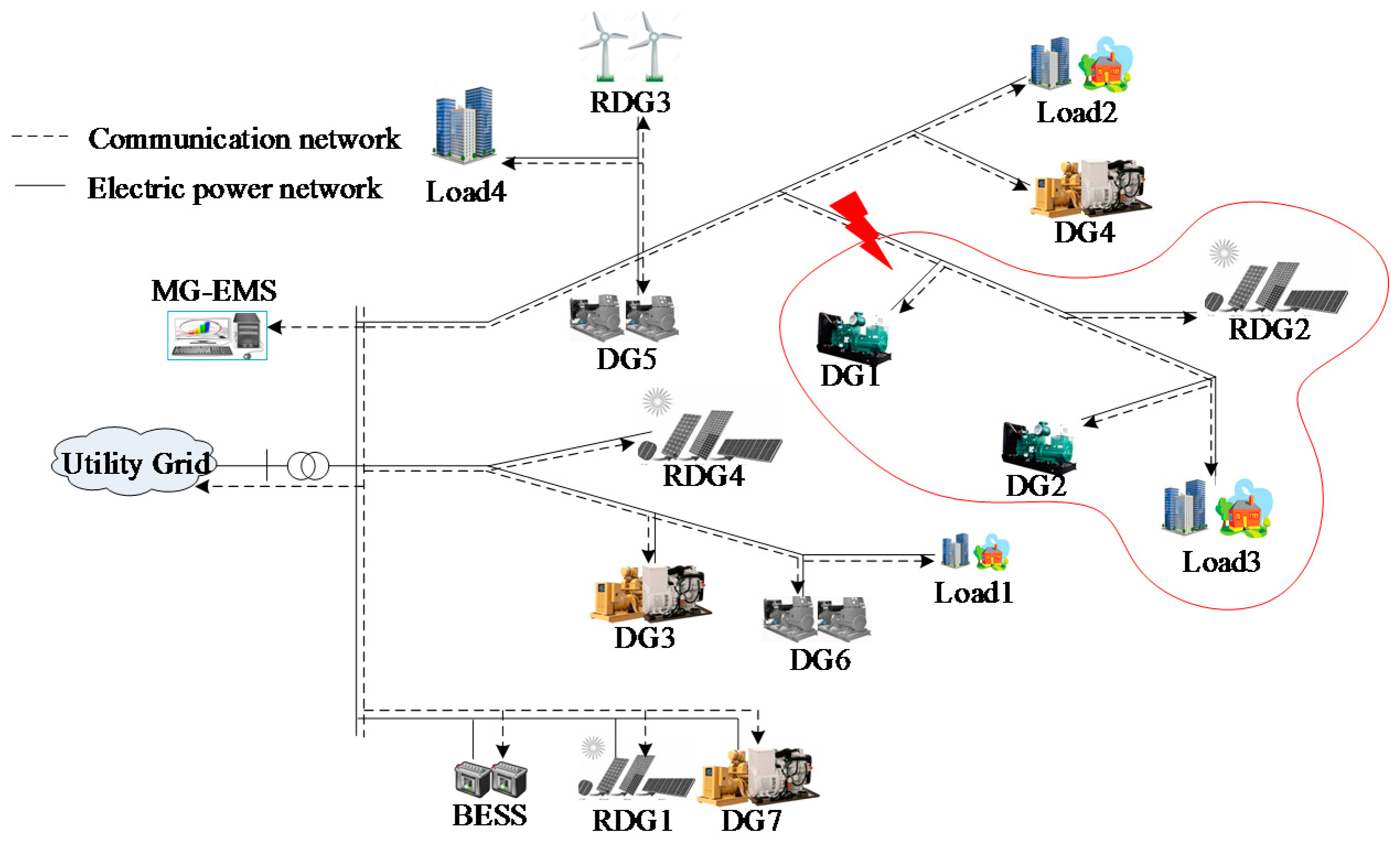
In this paper, an MG system is considered as a portion of electric network including diesel generators (DGs), battery energy storage system (BESS), renewable energy generators (RDGs), and loads, as shown in Figure 1. In normal operation, the MG system is operated by a centralized controller (MG-EMS). In this mode, each component informs its information to MG-EMS and receives its optimal schedule from the MG-EMS. The output power of DG units and charging/discharging amount of BESS are decided by the MG-EMS. The amount of power exchange between MG system and the utility grid is also determined by the MG-EMS to minimize the total operation cost and fulfill shortage power in the system. On the other hand, when an event occurs in the MG system, such as short circuit, over current of power electronic interfaces [18,19], the corresponding circuit breaker (CB) is opened to isolate the fault, thus some parts are disconnected from main system. MG system is divided into two parts: normal and isolated parts. In the worst case (losing both electrical connection and communication), the MG system has two separate parts and MG-EMS cannot control all components in the system. Therefore, the operation mode of MG is changed to emergency mode. In this mode, the normal part is still rescheduled by the MG-EMS while the isolated part could be out of service. Because the occurrence time of fault is not known, the operation problem is becoming a real-time problem and the convergence time is important for survival of the isolated part. Thus, all components in the isolated part could be rescheduled to another operation point as soon as possible without MG-EMS. By applying the proposed strategy, components (agents) in isolated system can communicate with each other to share their information and determine a new operation point in a short time. The system information is updated every time with the new faulty/recovered equipment. Whenever the system information is changed, the isolated part can reschedule without the MG-EMS.
2.2. Algorithm for Microgrid System Operation
The step-by-step procedure for performing one round of optimization is shown in Figure 2. In normal operation, agents inform their information to a centralized EMS (MG-EMS), such as buying and selling prices (hourly day-ahead market price signals), generation capabilities of DGs, RDGs, and BESS along with load profiles of MG system, which are taken as input data. After receiving all information, MG-EMS performs optimization and informs to participating agents with optimal results. The output power of each DG unit is decided by the comparison among the market price signals and its generation cost to minimize the operation cost of the MG system. The amount of exchanging power with the utility grid is decided to maintain the power balance in the system and maximize the profit. In peak intervals, the shortage power is fulfilled by importing electric power from the utility grid while the surplus power from cheap resources is sold to the utility grid in off-peak intervals. BESS is used to shift the surplus power from off-peak intervals to peak interval. The BESS is charged with cheap resources and discharged at expensive intervals for reducing the operation cost. If any event occurs in the MG system, faulty part is isolated from the system. The isolated part is considered as a distributed system, which is operated without MG-EMS. Thus, the MG system is changed to emergency operation mode.
In emergency operation mode, there are three possible disconnection scenarios:
- Losing the communication with the MG-EMS but maintaining the electrical connection with the normal part of MG.
- Maintaining the communication with the MG-EMS but losing the electrical connection with the MG.
- Losing both communication with the MG-EMS and the electrical connection with the normal part of MG.
In this paper, isolated/islanded refers to failure in both electrical and communication system. Power failure refers to failure in only electrical system and communication failure refers to failure in only communication system.
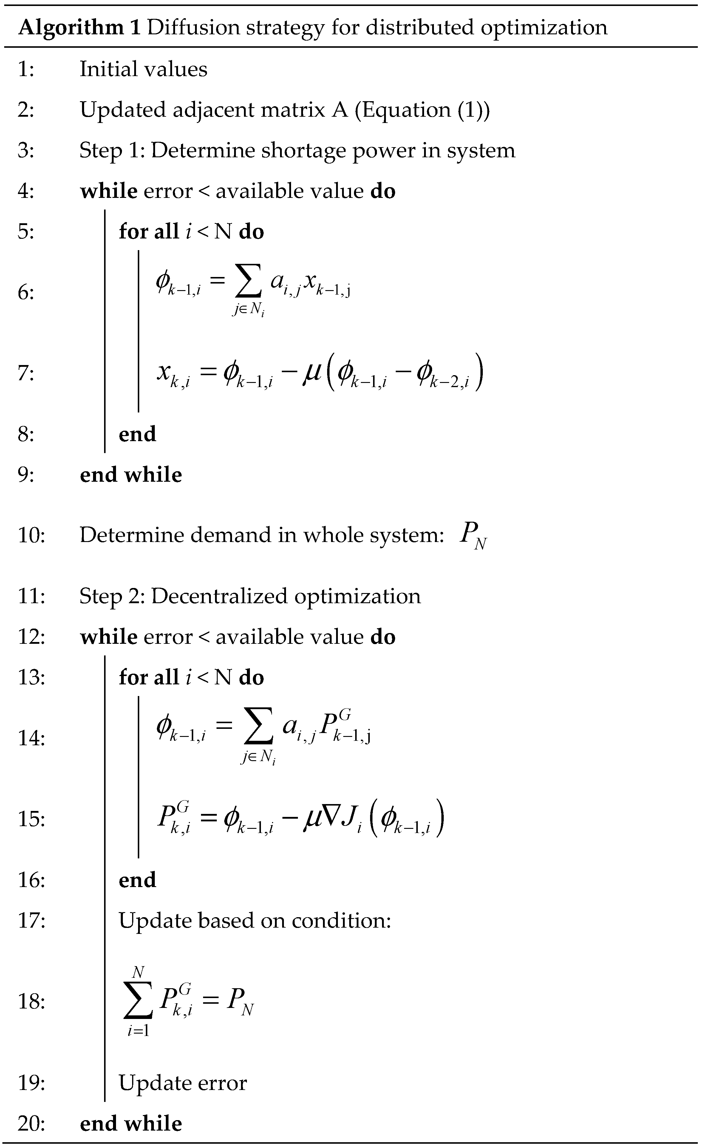
The normal part is rescheduled from the occurrence time of event by MG-EMS while the operation of the other part is rescheduled based on failure scenario, as explained above. In the case of Scenario 2, the MG-EMS can control all components in the MG system, so the two separated parts of the MG system are operated by MG-EMS without sharing power between two parts. In the case of Scenario 1 and Scenario 3, the MG-EMS cannot communicate with all components of faulty part and agents cannot receive the operation information from the MG-EMS. Therefore, each component (agent) shares its information with its neighbor agents and performs distributed optimization by using the proposed algorithm. The distributed optimization method for isolated part is explained in detail in Algorithm 1. The system information is updated every time with the new faulty/recovered equipment. Whenever the system information is changed or a new time interval is started, the MG system is rescheduled by applying the proposed algorithm.
2.3. Diffusion Strategy for Distributed Optimization
The proposed diffusion framework for an agent j is shown in Figure 3. In this figure, the agent j is only required to interact with the neighboring agents Nj (highlighted in Figure 3). In the case of fault, a corresponding circuit breaker (CB) should be opened to isolate the fault. It can lead to a situation where an agent and its neighboring agents are not electrically connected and are part of two separated sections. To prevent the diffusion of information between these neighboring agents, the agent checks the status of the corresponding CB and decides the neighboring agents for sharing its information based on the location of fault point. In this way, all the interactions are done in the network. The method is able to cope with different network topologies, and does not require the global information or relying on the central manager. The system topology is represented by an adjacent matrix A by using Metropolis rule [17,20], as given by Equation (1).
where are the number of neighboring agents of agent and , and when agent and is not connect.
To minimize the operation cost in the distributed system, global cost objective function of the system is defined by Equation (2), where Ji is the cost function of agent i. The real-valued vector of arguments w∈ℝn, representing the output power of each dispatchable agent (diesel generator). Therefore, the objective function (3) minimizes the global cost Jglob, and it is obtained by summing all individual cost functions. Each dispatchable agent has its own cost function. Therefore, each agent could have different objective functions in the case for the MG system. All Ji need to be differentiable, convex, and at least one Ji needs to be strong convex for reaching only one global minimum solution [21,22]. In this paper, the operation cost of each diesel generator (DG) unit is represented by a quadratic cost function and are all strong convex, as shown in Equation (4), where a, b, and c are the quadratic coefficients. Thus, Jglob is also strong convex and can reach optimization point. From the generation cost functions, the derivative of the cost function is given in Equation (5), which is also known as the marginal cost function. This equation is used for optimization diffusion algorithm to reach economic dispatch. The detailed mechanisms for performing distributed optimization has been explained more detail in the Algorithm 1.
In the proposed algorithm, each agent follows two steps: (1) information sharing diffusion for sharing the shortage amount; and (2) optimization diffusion for minimizing the operation cost. In Step 1, Combine-Then-Adapt (CTA) diffusion strategy is implemented to share information in the distributed system, as given in first two equations of Algorithm 1. At each iteration, the agent i updates its current state (xk−1,i) to a new state (xk,i) using the local stochastic gradient at this iteration. The local stochastic gradient available can be calculated from the difference of intermediate state at this iteration [17]. After finishing Step 1, the shortage amount in the system is known in the distributed system. In Step 2, namely decentralized optimization, similar to Step 1, CTA diffusion strategy is used for distributed optimization, as shown in last three equations of Algorithm 1. However, in this step, the gradient of the cost function is used instead of the stochastic gradient ().

2.4. Interaction among Agents in the Microgrid System
In the normal operation, all agents communicate with the MG-EMS agent by using agent communications language (ACL) messages. The interaction among agents of the proposed strategy is illustrated in Figure 4. Firstly, a message is sent by MG-EMS agent to market agent to inquire about the market price signals. The market agent sends the day-ahead buying and selling prices for each hour of the day to MG-EMS agent. The MG-EMS agent will inform its local resources about the market price signals along with call for proposal (cfp) messages. The local elements of MG system propose their proposals for operation scheduling. Based on the proposals received from its local elements, the MG-EMS agent decides to accept/reject the proposals from its local agents. After receiving the acceptance/rejection of their proposals, each local agents implement its operation scheduling and informs the MG-EMS. Finally, the MG-EMS decides the amount of buying/selling power with the utility grid based on the amount of shortage/surplus power in the MG system. Communication between all the agents is realized through ACL by using a modified contract net protocol (MCNP) [23].
In the emergency operation, isolated agents cannot communicate to the MG-EMS agent. The operation of normal agents is rescheduled by MG-EMS agent, similar to normal mode. On the other hands, each isolated agent communicates to its neighbor agents for sharing its information and performing distributed optimization based on its receiving information. The state diagram of each agent in the isolated part is shown in Figure 5. Firstly, each agent receives information from all its neighbor agents and updates the information of the amount of shortage power in the isolated part. The updated information will be sent to the neighbor agents. After the shortage power information of all agents has reached convergence, the amount of shortage power in the system is determined. Then, the economic dispatch is started by using the optimization diffusion. Each agent shares its information to its neighbor agents and updates its generation output to fulfill the amount of shortage power in the isolated part. When the information sharing converges once again, the generation amount of each DG unit is determined for isolated part.
2.5. Scheduling Horizons
The two possible operation modes of the proposed microgrid are normal mode and emergency mode. Each of the operation modes has a different scheduling horizon as depicted in Figure 6. The scheduling horizon for normal mode is 24 h (T) and operation is based on the day-ahead model. If any event occurs at time h, the MG-EMS will switch its operation mode to emergency mode. The scheduling horizon of the emergency mode is from t = h to the end of the day (T). If any event occurs, the MG system is divided into two parts: normal part and isolated part. In normal part, the operation of all components is rescheduled by the MG-EMS while the isolated part is considered as a distributed system. To reschedule the operation of all components in isolated part, each component (agent) will communicate to its neighbor agents and perform distributed optimization to make new operation point. At each time interval, the number of normal/isolated equipment (agents) is updated in the MG system. The scheduling for all components is determined by using the MG-EMS (normal part) and diffusion strategy (isolated part). Finally, if the event is fully cleared, the MG-EMS will switch back to normal operation mode depending on its input values. Generally, a scheduling horizon of one day is considered for scheduling of microgrids [24,25]. Therefore, in this study, simulations are conducted for one day. However, the formulated mathematical models can be used to extend the simulations for longer durations by iterating the scheduling window.
3. Problem Formulation
A hierarchical control structure has three levels based on the required time frame: primary, secondary, and tertiary controls [26,27].
- Primary control is designed to preserve voltage, frequency stability and plug and play capability of distributed energy resources (DERs).
- Secondary control is designed to compensate the voltage and frequency deviation caused by primary control.
- Tertiary control is designed for optimal operation of MGs and/or deciding the amount of power sharing with the utility grid (in grid-connected mode).
In this paper, we focus on the tertiary control and set long-term set points based on the status of the distributed energy resource units, market price signals, and other system requirements. It is responsible for managing MG system in an economical way. Therefore, the constraints related to the primary control and secondary control are assumed to be fulfilled, and out of the scope for this paper.
In the following section, the day-ahead operation planning of an MG system is determined by solving an optimization problem for both normal and emergency operation mode. The proposed model is formulated for 24 h with any uniform interval of time t. However, in the proposed day-ahead scheduling model, t has been assumed to be one hour.
3.1. Normal Mode
3.1.1. Objective Function
The objective of the normal operation is to minimize the operation cost of the MG system, as shown in Equation (6). The first term of the objective function contains generation cost, start-up cost, and shut-down cost of DGs. The second term contains profit gained by trading electricity with the utility grid:
In this paper, the operation cost of each DG unit is represented by a quadratic cost function, as shown in Equation (4).
3.1.2. Constraints for Operation of MG System
Power generated by RDGs, DG units, discharged amount, and buying amount from the utility grid should be balanced with load, charging amounts, and selling amount from the utility grid at each interval, as shown by (7):
Equations (8)–(11) show the constraints for each diesel generator units. Equation (8) represents the operation bounds of DG unit g at time t. The on-off mode of DG is determined by Equation (9). The start-up and shutdown status is determined based on the on-off mode of each DG unit, as shown in Equations (10) and (11). Equations (12) and (13) depicts the ramp-up and ram-down constraints for gth DG unit:
where
The BESS model in MG system can be represented by using Equations (14)–(17). The bounds of charging/discharging amount is given by Equations (14) and (15). Each interval, the state of charge (SOC) of BESS is updated according to the charging/discharging amount and previous interval’s SOC, as given by (16). The SOC of the BESS at any time interval t is constrained by Equation (17):
3.2. Emergency Mode
The scheduling horizon of emergency operation is from the event occurrence time (at interval h) to the end of the day (at interval T). In this mode, the MG-EMS will reschedule for all components in the normal part. The components in isolated part perform distributed optimization by using diffusion strategy.
3.2.1. Objective Function
Whenever a fault occurs, the corresponding circuit breaker (CB) is opened to isolate the fault. By using the information of fault location, which is sent from the corresponding CB, each single agent is able to know that it is electrically islanded or not from the MG. Therefore, the number of agents is determined in each part. In normal part, all components are rescheduled by EMS. In isolated part, each agent determines its new operation point by using diffusion strategy. The cost objective function of the MG system in emergency operation is given by Equation (18). The first term of Equation (18) represents the operation cost, start-up cost, and shut-down cost of DG units in the normal part. The second term of Equation (18) shows profit of exchanging electric power between the utility grid. The total operation cost of isolated part is presented by Equation (19), which includes the operation cost, start-up cost, shut-down cost of DG units, and the penalty of load shedding in this system. The output power of DGs and load shedding amount are determined by using diffusion strategy.
where
3.2.2. Constraints for Operation of MG System
Equation (20) shows that the power generated by RDGs, DGs, BESS discharging amount, and power bought from the utility grid should be balanced with charging amount, load amount, and the amount of power sold to the utility grid. Similarly, the power balancing between supplies and loads is given by Equation (22) for isolated part considering the load shedding in peak intervals. In addition to Equations (20)–(22), Equation (18) is also constrained to Equations (8)–(17).
where
4. Numerical Simulations
In this study, the test MG system considered for simulations is similar to Figure 1. Firstly, the normal operation mode is considered and the MG system is operated based on day-ahead scheduling. A fault is considered at interval 10, the fault occurs during a very short time. It is isolated as soon as possible by opening the corresponding circuit breakers. In this way, some parts of the MG could be isolated from main system and could not communicate with the MG-EMS. Therefore, the MG system is changed to emergency mode operation. The proposed strategy operation is used to operate the MG system in an economical way for both normal and isolated parts after isolating the fault. The isolated part is operated by using diffusion strategy while normal part is operated by MG-EMS. At interval 15, one part is recovered from the event. The number of agents in normal/isolated part is updated and the normal part is rescheduled by MG-EMS while the isolated part is rescheduled by using diffusion strategy. Finally, at interval 20, the event is fully cleared and the entire MG system is rescheduled by MG-EMS to the end of day (t = 24). The proposed model has been implemented on a computer with an Intel(R) Core i5(TM) 2500 CPU @ 3.30 GHz and 8 GB of RAM memory using Java (Oracle Corporation, Redwood City, CA, USA), JADE (Oracle Corporation, Redwood City, CA, USA) with integration of IBM ILOG CPLEX (International Business Machines Corporation, Armonk, NY, USA).
4.1. Input Parameters
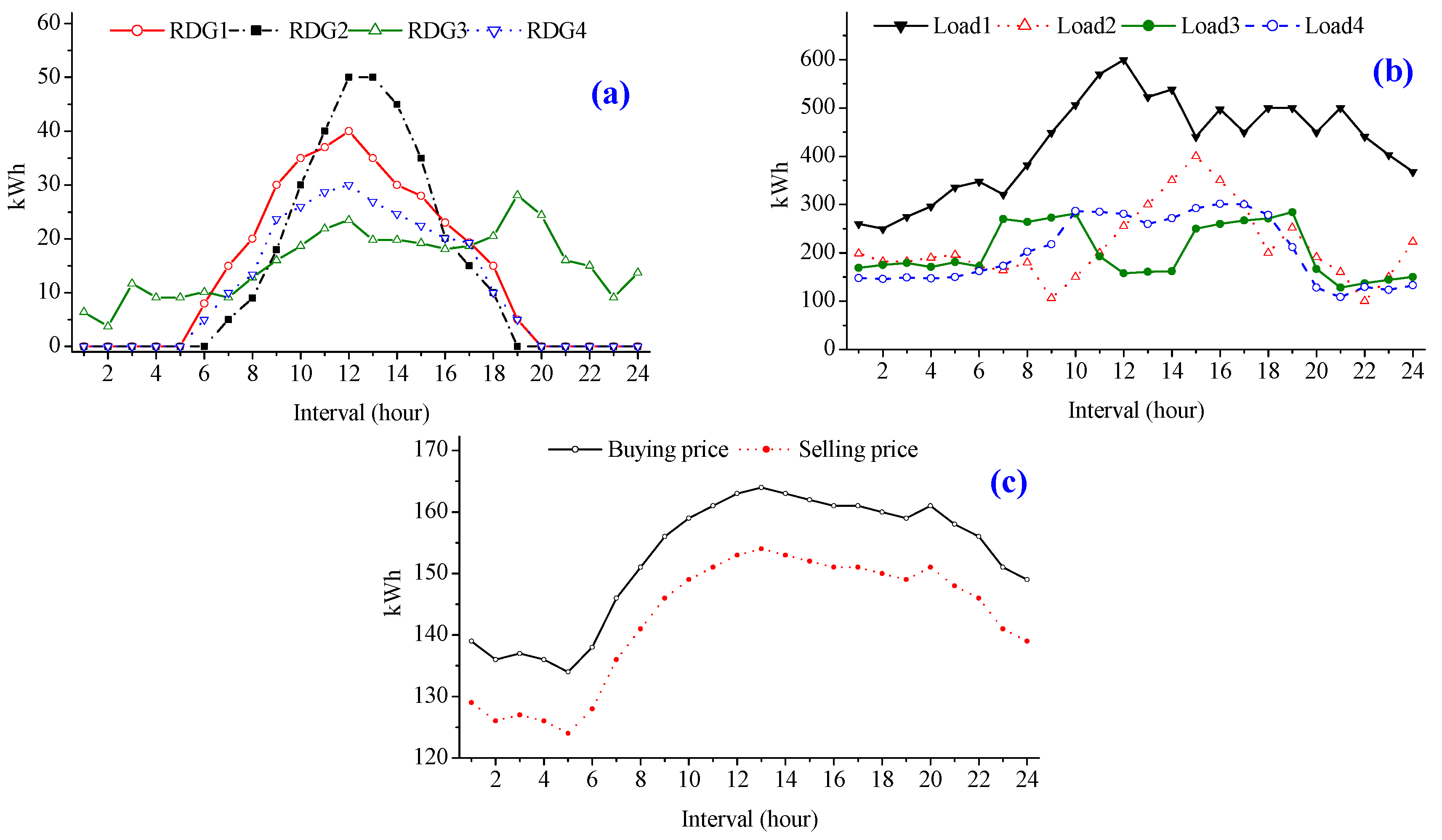
Figure 7 shows the hourly generation amount of RDGs, the hourly electric loads of the MG system, and the market price signals, which are taken as input data. The maximum value and the initial value of BESS are 200 kWh and 50 kWh, respectively. The charging/discharging loss of BESS is 5%. The parameters related to DG units of the MG system are also shown in Table 1.
4.2. Piecewise Method Linearization
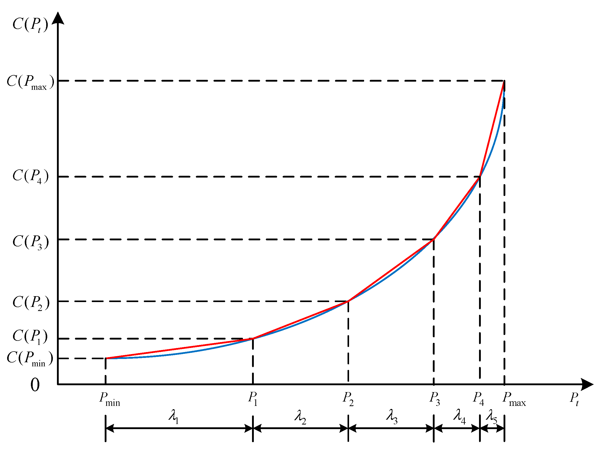
The cost objective functions (6) and (18) are nonlinear, therefore piecewise linearization method has been used to transform them into linear counterparts. As shown in Figure 8, the cost function of generator is approximated by using a set of piecewise blocks. The analytic representation of this linear approximation is [28,29]:
where is considered as constant cost in segment i
The generation cost is approximated by Equation (23), where the generation amount is divided into many segments between , . The per unit generation cost is consedered as a constant value in each segment, which is calculated as the slope of the approximated generation cost cuver in each segment. The approximated generation cost is shown in Figure 8 (red curve). Equations (24)–(26) represent the generation amount of gth DG at interval t in each segment. Finally, the total output power of the DG is calculated by Equation (27).
4.3. Normal Operation Mode
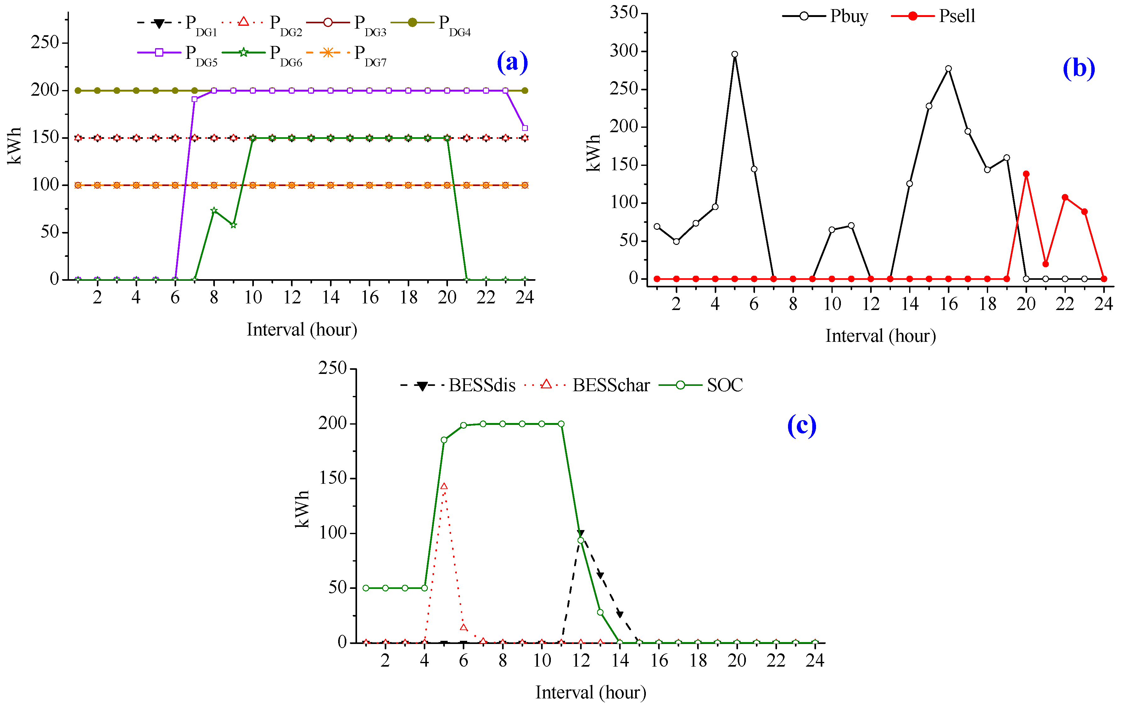
In normal operation mode, the entire MG system is operated by MG-EMS based on day-ahead scheduling for minimizing the total operation cost. The simulated scenario for evaluating the performance of proposed strategy is shown in Figure 9. It can be observed from Figure 9a that the generation amount of DGs is determined by the comparison between generation cost of DG units and market price signals. The DG units having lower generation costs (DG1–DG4, and DG7) are always set to maximum. During off-peak price intervals (intervals 1–6), the DG units having higher generation costs (DG5 and DG6) are set to minimum and the shortage amount is fulfilled by buying electricity from the utility grid in order to minimize the MG’s operation cost. In peak price intervals (intervals 8–10), DGs are set to maximum and surplus is sold to the utility grid to increase the profit. The amount of exchanged power with the utility grid is depicted in Figure 9b. Electricity is bought from the utility grid for fulfilling the shortage power and avoiding the use of expensive resources. Similarly, electricity is sold to the utility grid to increase the profit by selling electric power from the cheap resources. BESS are charged during the off-peak intervals (intervals 5 and 6) and are discharged during the peak price intervals (intervals 12–14) as shown in Figure 9c. The BESS is used either to fulfill the local demand of MG system or to trade power with the utility grid.
4.4. Emergency Operation Mode
In emergency mode, two cases are simulated. In the first case, an event is considered at interval 10, point N1, which divides the MG system into two parts: normal part and isolated part, (Figure 10). In the second case, at interval 15, one part is recovered from the event (Figure 14).
4.4.1. Case 1: Event at Interval 10 at N1
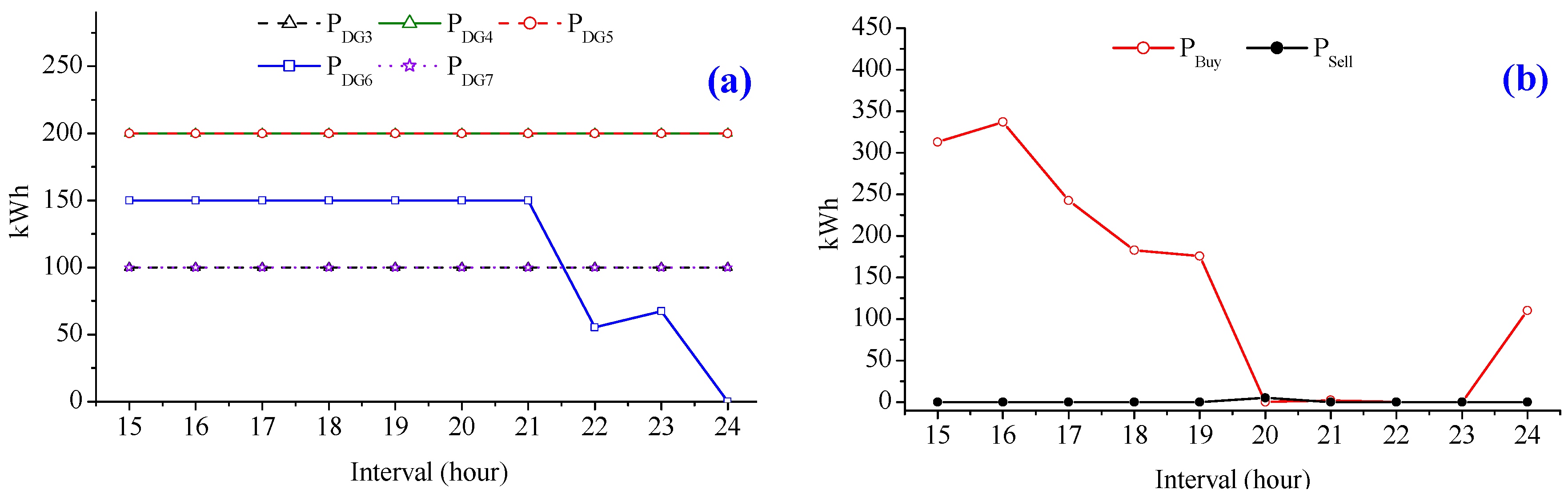
According to the proposed algorithm, the normal part (outside the red area) in MG system is rescheduled by MG-EMS from interval 10 to 24. The output power of DG units (DG3, and DG5–DG7) is rescheduled from interval 10 to 24, as shown in Figure 11a. Figure 11b shows the amount of exchanging power with the utility grid. Due to the isolation of DG units (DG1, DG2, and DG4), the generated amount from these DG units cannot supply to the demand of normal part in the MG system. Therefore, the amount of buying power is increased to fulfill the shortage power in the MG system while the amount of selling power is decreased to zero. BESS is rescheduled with the new initial value of SOC, which is taken at occurrence time of the event, i.e., SOCinitial = SOC(10). In this case, the amount of shortage in the system is high. Therefore, the BESS is only discharged to reduce the amount of buying power from the utility grid.
The faulty part (in the red area) is considered as a distributed system. The output power of DG units (DG1, DG2, and DG4) should fulfill the load amount in this area considering three different failure scenarios, as mentioned in Section 2.2. In Scenario 2, the faulty part (power failure part) is also rescheduled by MG-EMS without power sharing between the two areas. The output power of DG units is shown in Figure 12a for minimizing the operation cost of the entire system. To maintain the power balance in this area, in some peak intervals (15–17, and 19), load shedding should be implemented. The amount of load shedding is shown in Figure 12b for maintaining the power balance.
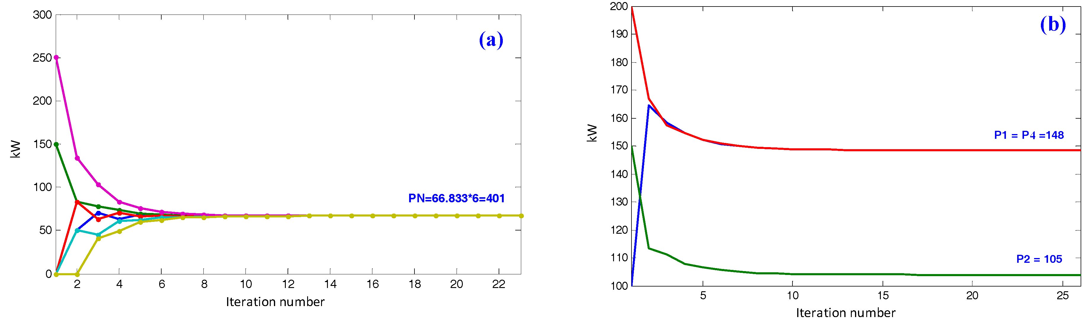
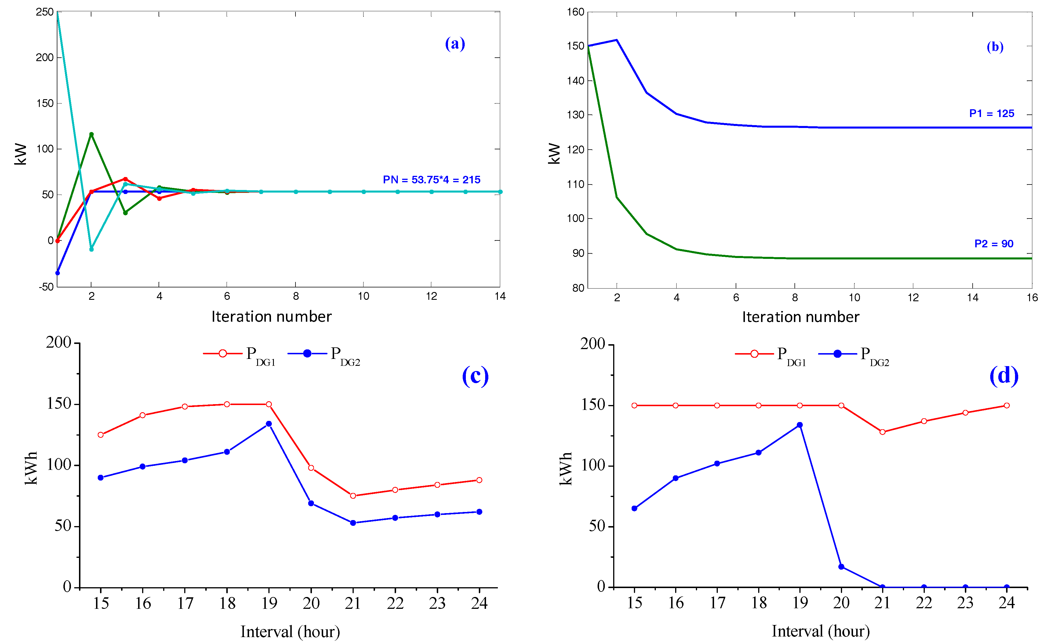
To reschedule for this area with Scenarios 1 and 3, each agent shares its information with its neighbor agents to get the shortage amount in the system. By applying Algorithm 1, the shortage power and the new operation point of these DG units are determined for interval 10 (at occurrence time of the event), as shown in Figure 13. The shortage power information of all agents converges to the value 66.833 kW, which is the average of the shortage amount requirement. The shortage power (PN) is equal to the difference between total loads (load 1 and load 2) and the output power of RDG2. Based on the information of the shortage amount in the distributed system, the output power of DG units is determined to maintain the power balance and to minimize the operation cost. At interval 10, the output power of DG1, DG2 and DG4 is 148 kW, 105 kW and 148 kW, respectively. The output power of each DG depends on the operation cost of that DG.
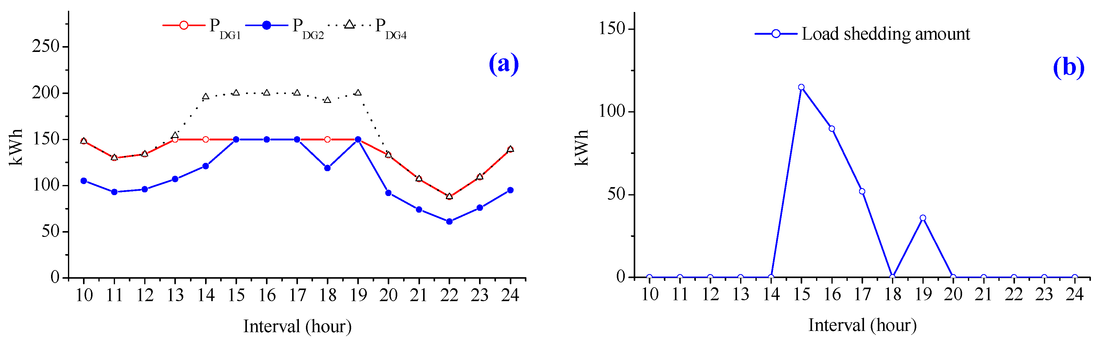
Similarly, the output power of these DG units is rescheduled by applying the proposed algorithm for remaining intervals (from interval 10 to 24), as shown in Figure 14a. The output power of DG units is determined by sharing information among agents to minimize the total operation cost and maintain the balance of supply and demand. In off-peak intervals, generation amount can fulfill the load amount. However, in peak intervals (intervals 14–17, and 19), although all DG units are set to their maximum values, they cannot fulfill all loads. To maintain the power balance in the distributed system, load shedding should be implemented. The amount of load shedding is shown in Figure 14b.
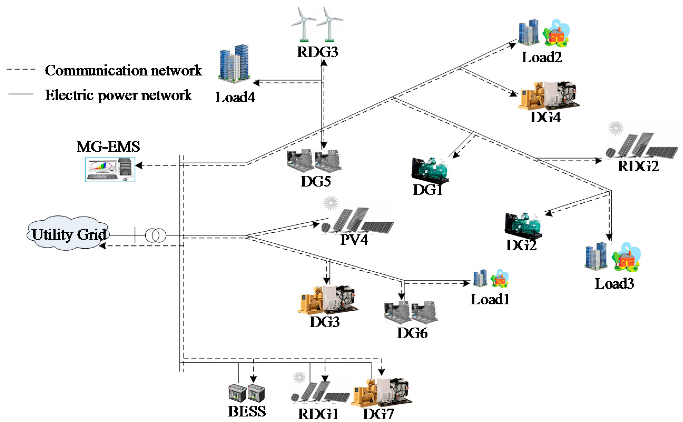
4.4.2. Case 2: Recovered One Part from the Event at Interval 15
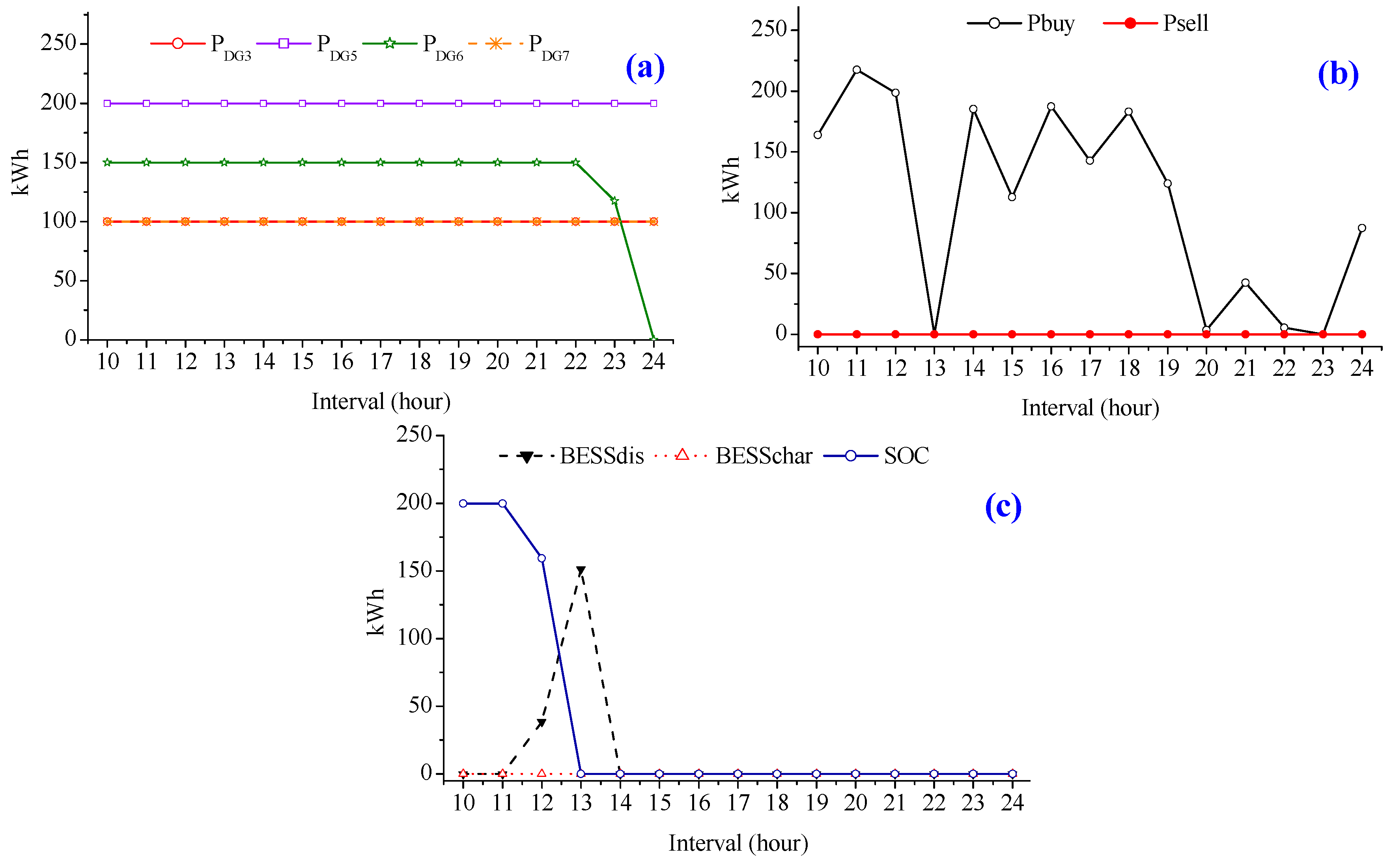
In this case, we assume that some equipment (DG4 and load 2) are recovered from the event at interval 15 as shown in Figure 15. According to the proposed algorithm, the normal part is updated with new recovered equipment and rescheduled by MG-EMS from interval 15 to 24. The amount of DG units is set based on the optimal values from MG-EMS, as shown in Figure 16a. Due to the reconnection of cheap resource (DG4), the output power of expensive resource (DG6) has been decreased to minimize the operation cost in off-peak intervals (intervals 22 and 23). The shortage power is fulfilled by buying electric power from the utility gird while the surplus power is sold for getting profit in some off-peak intervals. The amount of exchanging power with the utility grid is depicted in Figure 16b. At interval 15, BESS is fully discharged (SOC(15) = 0) while the price for charging is high. Therefore, the SOC of BESS is set to zero for reaming intervals.
In the distributed system, the number of agents is updated considering the number of recovered equipment (agents). Similarly, in Scenario 2, the MG-EMS reschedules to minimize total operation cost for both normal and power failure areas. The output power of DG units for remaining intervals is illustrated by Figure 17d. The DG (DG1) having low operation cost is always set to the maximum value before using the DG (DG2) having higher operation cost. In Scenarios 1 and 3, each agent shares its information with its neighbor agents to get the information of shortage amount in the system. At interval 15, the amount of shortage power came out to be PN that is equal to the difference between load 3 and the output power of RDG2, as shown in Figure 17a. After determining the shortage amount, the proposed distributed optimization method is used to determine the output power of DG units (DG1 and DG2). The output power of DG1 and DG2 is decided to maintain the power balance in the isolated part and to minimize the operation cost, as given in Figure 17b. Similarly, the DG units are rescheduled for all remaining intervals (intervals 15–24) as shown in Figure 17c. In this case, the generated amount can fulfill the load amount in all remaining intervals. Therefore, the amount of load shedding is reduced to zero.
4.5. Fault Recovery at Interval 20
At interval 20, all isolated part is recovered from the event. The schedules of all components are also recovered, similar to normal operation. The MG system is operated by MG-EMS based on day-ahead scheduling. Therefore, the operation of DG units, the amount of exchanging power, the amount of BESS charging/discharging, and the SOC of BESS are similar to Figure 9a–c from interval 20 to the end of day.
4.6. Comparison between Consensus Algorithm and Diffusion Strategy
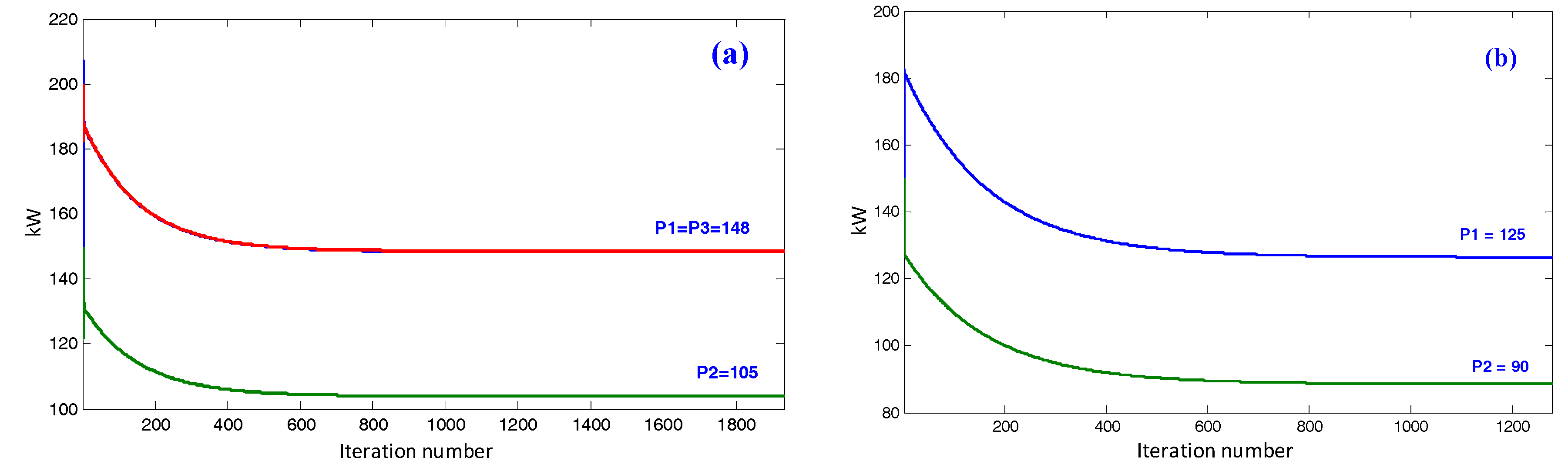
In this section, the comparison between consensus algorithm and diffusion strategy is presented to show the advantage of the proposed algorithm. In the isolated part, the DG units are rescheduled by using the proposed algorithm based on the diffusion strategy for each case of emergency operation mode, which are shown in Figure 12 and Figure 16. Figure 18a,b shows the output power of DG units by using the consensus algorithm in the isolated part for interval 10 (Case 1) and interval 15 (Case 2). By comparing the results of the consensus algorithm and the proposed diffusion strategy, it can be conclude that the proposed strategy has converged faster than the consensus algorithm.
Table 2 shows the summary of the results of both the consensus algorithm and the diffusion strategy for first interval operation of distributed system. In the Case 1, the number of agents in distributed system is 6. The reductions of iteration and calculation time are 97.4% and 31.25%, respectively, compared with the consensus algorithm. In Case 2, due to the recovered equipment, the number of agents is reduced to 4. The reductions of iteration and calculation time are 97.6% and 28.6%, respectively, compared with the consensus algorithm. Therefore, it can be conclude that the diffusion strategy is better when the size of the distributed system is increasing.
It can be observed in Table 2 that, in a small distributed system, the calculation time of both diffusion and consensus approaches are very fast. However, when the size of distributed system is increased, consensus algorithm can lead to drastic increase in number of iterations while the numbers of iterations are gradually increasing for the diffusion strategy. Therefore, in the case of a large system, the impact of the proposed method is more significant compared with the consensus algorithm [17].
5. Conclusions
A novel operation strategy for enhancing the reliability of microgrids is proposed using diffusion strategy. The MG system can operate in an economic way in both normal and emergency operation modes. In normal operation mode, the MG system is operated by MG-EMS for minimization of operation cost. In emergency operation mode, the MG system is divided into normal and isolated parts. Normal part is still operated by MG-EMS while the isolated part is considered as a distributed system. The proposed strategy maintains this part, which is also operated in an economic way by using diffusion strategy for minimizing global cost without a central controller. The numerical results have shown that a multiagent system based on the diffusion strategy has a desirable performance compared with consensus method and can be easily applied for microgrid optimization. During emergency operation, in isolated part, the number of iterations and the calculation time was reduced by 97% and 28.6%, respectively, as compared with the consensus algorithm. The proposed operation strategy is suitable to apply for a distributed system. By applying the proposed strategy, the system can be operated in an economical way without an energy management system.
Another application of the proposed method is in large-scale microgrids, where, after the occurrence of a fault, the isolated part could be out of service. It leads to a large amount of load to be interrupted, thus, the proposed strategy can be used to solve this problem by using diffusion strategy. In this way, each agent can communicate with neighboring agents to determine a new operation point.
Acknowledgments
This work was partially supported by the Power Generation & Electricity Delivery Core Technology Program of the Korea Institute of Energy Technology Evaluation and Planning (KETEP), granted financial resource from the Ministry of Trade, Industry & Energy, Republic of Korea. (No. 20141020402350) and partially supported by the Korea Institute of Energy Technology Evaluation and Planning (KETEP) and the Ministry of Trade, Industry & Energy (MOTIE) of the Republic of Korea (No. 20151210200080).
Author Contributions
The paper was a collaborative effort between the authors. The authors contributed collectively to the theoretical analysis, modeling, simulation, and manuscript preparation.
Conflicts of Interest
The authors declare no conflict of interest.
Abbreviations
| Index of time, running from 1 to | |
| Index for total, normal part, and isolated part DGs, respectively | |
| Index for total, normal part, and isolated part loads, respectively | |
| Index for total, normal part, and isolated part DRGs, respectively | |
| Commitment, startup, and shutdown status identifier of gth DG at t | |
| Generation cost of DG unit g at t | |
| , | Start-up and shutdown cost of DG unit g at t |
| , | Price for buying and selling power to/from the utility grid at t |
| Amount of power generated by DG g at t | |
| , | Total amount of power bought from and sold to the utility grid at t |
| Electric load l of microgrid at t | |
| Amount of power generated by RDG unit r at t | |
| Minimum and maximum generation amount of gth DG unit | |
| Ramp-up and Ramp-down time of gth DG unit | |
| , | Amount of electrical energy charged/discharged to/from BESS at t |
| , | Charging and discharging losses of BESS unit |
| Capacity and SOC of BESS unit | |
| Lower and upper limits for SOC of BESS unit | |
| Total amount of shed load and penalty cost for load shedding at t | |
| The generation amount of DG in segment i at t | |
| The value to determine the segment i from |
References
- Hatziargyriou, N.; Asano, H.; Iravani, R.; Marnay, C. Microgrids. IEEE Power Energy Mag. 2007, 5, 78–94. [Google Scholar] [CrossRef]
- Kim, H.M.; Lim, Y.; Kinoshita, T. An intelligent multiagent system for autonomous microgrid operation. Energies 2012, 5, 3347–3362. [Google Scholar] [CrossRef]
- Bui, V.H.; Hussain, A.; Kim, H.M. A multiagent-based hierarchical energy management strategy for multi-microgrids considering adjustable power and demand response. IEEE Trans. Smart Grid 2016. [Google Scholar] [CrossRef]
- Tsikalakis, A.G.; Hatziargyriou, N.D. Centralized control for optimizing microgrids operation. IEEE Trans. Energy Convers. 2008, 23, 241–248. [Google Scholar] [CrossRef]
- Conti, S.; Nicolosi, R.; Rizzo, S.A.; Zeineldin, H.H. Optimal dispatching of distributed generators and storage systems for MV islanded microgrids. IEEE Trans. Power Deliv. 2012, 27, 1243–1251. [Google Scholar] [CrossRef]
- Olivares, D.E.; Cañizares, C.A.; Kazerani, M. A centralized energy management system for isolated microgrids. IEEE Trans. Smart Grid 2014, 5, 1864–1875. [Google Scholar] [CrossRef]
- Song, N.O.; Lee, J.H.; Kim, H.M.; Im, Y.H.; Lee, J.Y. Optimal energy management of multi-microgrids with sequentially coordinated operations. Energies 2015, 8, 8371–8390. [Google Scholar] [CrossRef]
- Colson, C.M.; Nehrir, M.H. Algorithms for distributed decision-making for multi-agent microgrid power management. In Proceedings of the 2011 IEEE Power and Energy Society General Meeting, Detroit, MI, USA, 24–29 July 2011; pp. 1–8. [Google Scholar]
- Cha, H.J.; Won, D.J.; Kim, S.H.; Chung, I.Y.; Han, B.M. Multi-agent system-based microgrid operation strategy for demand response. Energies 2015, 8, 14272–14286. [Google Scholar] [CrossRef]
- Lynch, N.A. Distributed Algorithms; Morgan Kaufmann Publishers Inc.: San Francisco, CA, USA, 1996. [Google Scholar]
- Ren, W.; Beard, R.W.; Atkins, E.M. A survey of consensus problems in multi-agent coordination. In Proceedings of the 2005 American Control Conference, Portland, OR, USA, 8–10 June 2005; pp. 1859–1864. [Google Scholar]
- Meng, L.; Dragicevic, T.; Guerrero, J.M.; Vasquez, J.C. Dynamic consensus algorithm based distributed global efficiency optimization of a droop controlled DC microgrid. In Proceedings of the 2014 IEEE International Energy Conference (ENERGYCON), Cavtat, Croatia, 13–16 May 2014; pp. 1276–1283. [Google Scholar]
- Xu, Y.; Li, Z. Distributed optimal resource management based on the consensus algorithm in a microgrid. IEEE Trans. Ind. Electron. 2015, 62, 2584–2592. [Google Scholar] [CrossRef]
- Hug, G.; Kar, S.; Wu, C. Consensus + innovations approach for distributed multiagent coordination in a microgrid. IEEE Trans. Smart Grid 2015, 6, 1893–1903. [Google Scholar] [CrossRef]
- Zhang, Z.; Chow, M.Y. Convergence analysis of the incremental cost consensus algorithm under different communication network topologies in a smart grid. IEEE Trans. Power Syst. 2012, 27, 1761–1768. [Google Scholar] [CrossRef]
- Hussain, A.; Bui, V.H.; Kim, H.M. A resilient and privacy-preserving energy management strategy for networked microgrids. IEEE Trans. Smart Grid 2016. [Google Scholar] [CrossRef]
- De Azevedo, R.; Cintuglu, M.H.; Ma, T.; Mohammed, O.A. Multi-agent based optimal microgrid control using fully distributed diffusion strategy. IEEE Trans. Smart Grid 2017, 8, 1997–2008. [Google Scholar] [CrossRef]
- Laaksonen, H.; Kauhaniemi, K. Fault type and location detection in islanded microgrid with different control methods based converters. In Proceedings of the 19th International Conference on Electricity Distribution (CIRED), Vienna, Australia, 21–24 May 2007; pp. 372–376. [Google Scholar]
- Ali, H.; Reza, I. Microgrid Protection. Proc. IEEE 2017, 105, 1332–1353. [Google Scholar]
- Sayed, A.H. Adaptive networks. Proc. IEEE 2014, 102, 460–497. [Google Scholar] [CrossRef]
- Chen, J.; Sayed, A.H. Diffusion adaptation strategies for distributed optimization and learning over networks. IEEE Trans. Signal Process. 2012, 60, 4289–4305. [Google Scholar] [CrossRef]
- Chen, J.; Sayed, A.H. Distributed Pareto optimization via diffusion strategies. IEEE J. Sel. Top. Signal Process. 2013, 7, 205–220. [Google Scholar] [CrossRef]
- FIPA. The Foundation for Intelligent Physical Agents Standards. Available online: http://www.fipa.org (accessed on 30 June 2017).
- Liu, Y.; Hou, X.; Wang, X.; Lin, C.; Guerrero, J.M. A coordinated control for photovoltaic generators and energy storages in low-voltage AC/DC hybrid microgrids under islanded mode. Energies 2016, 9, 651. [Google Scholar] [CrossRef]
- Wang, Z.; Wang, J. Self-healing resilient distribution systems based on sectionalization into microgrids. IEEE Trans. Power Syst. 2015, 30, 3139–3149. [Google Scholar] [CrossRef]
- Bidram, A.; Davoudi, A. Hierarchical structure of microgrids control system. IEEE Trans. Smart Grid 2012, 3, 1963–1976. [Google Scholar] [CrossRef]
- Yazdanian, M.; Mehrizi-Sani, A. Distributed control techniques in microgrids. IEEE Trans. Smart Grid 2014, 5, 2901–2909. [Google Scholar] [CrossRef]
- Carrión, M.; Arroyo, J.M. A computationally efficient mixed-integer linear formulation for the thermal unit commitment problem. IEEE Trans. Power Syst. 2006, 21, 1371–1378. [Google Scholar] [CrossRef]
- Tenfen, D.; Finardi, E.C.; Delinchant, B.; Wurtz, F. Lithium-ion battery modelling for the energy management problem of microgrids. IET Gener. Transm. Distrib. 2016, 10, 576–584. [Google Scholar] [CrossRef]
Figure 1.
An illustration of a typical microgrid system.

Figure 2.
Flowchart for operation of the microgrid system.
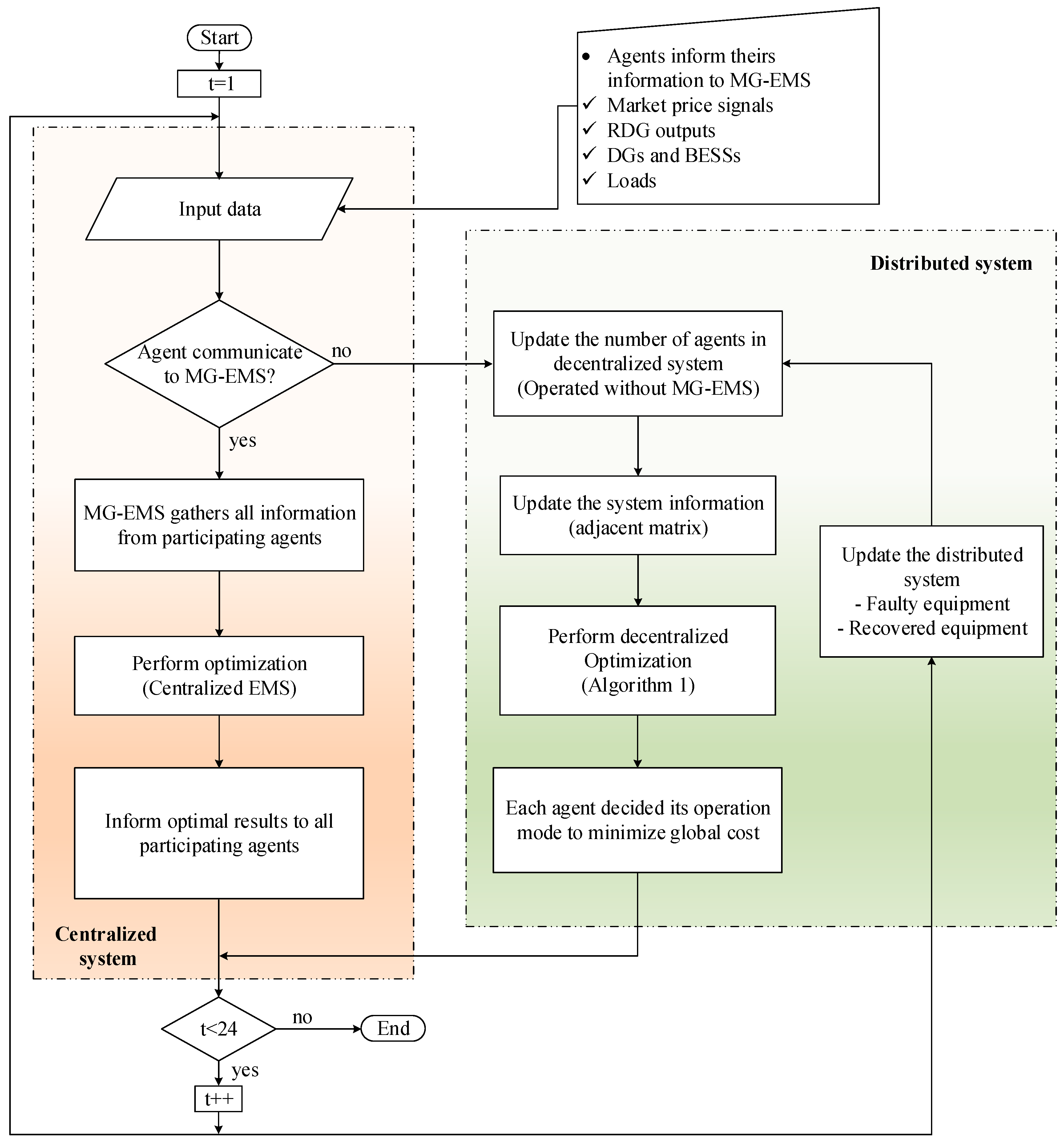
Figure 3.
Neighborhood agents of agent j (the highlighted area).
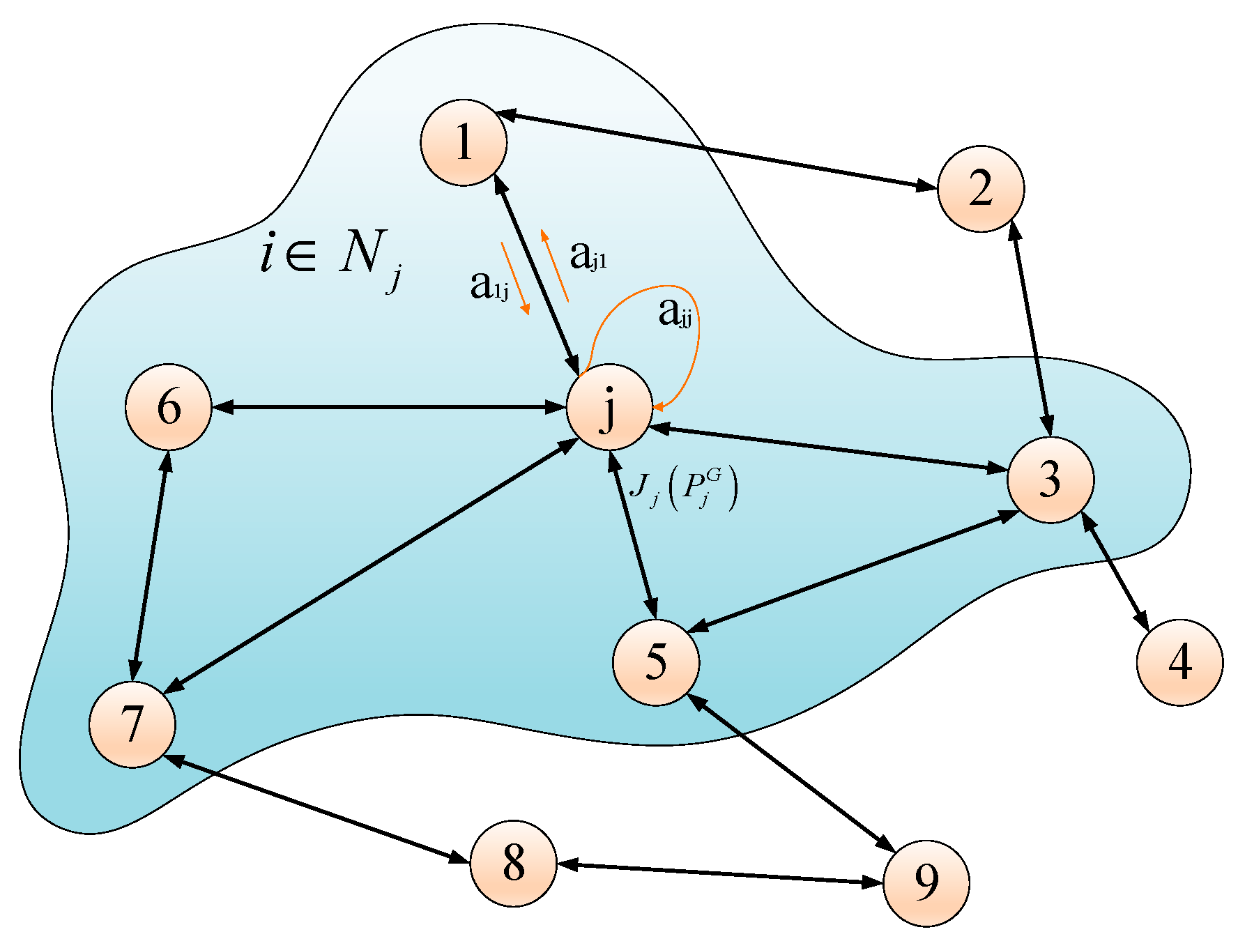
Figure 4.
Agents communication in normal operation.
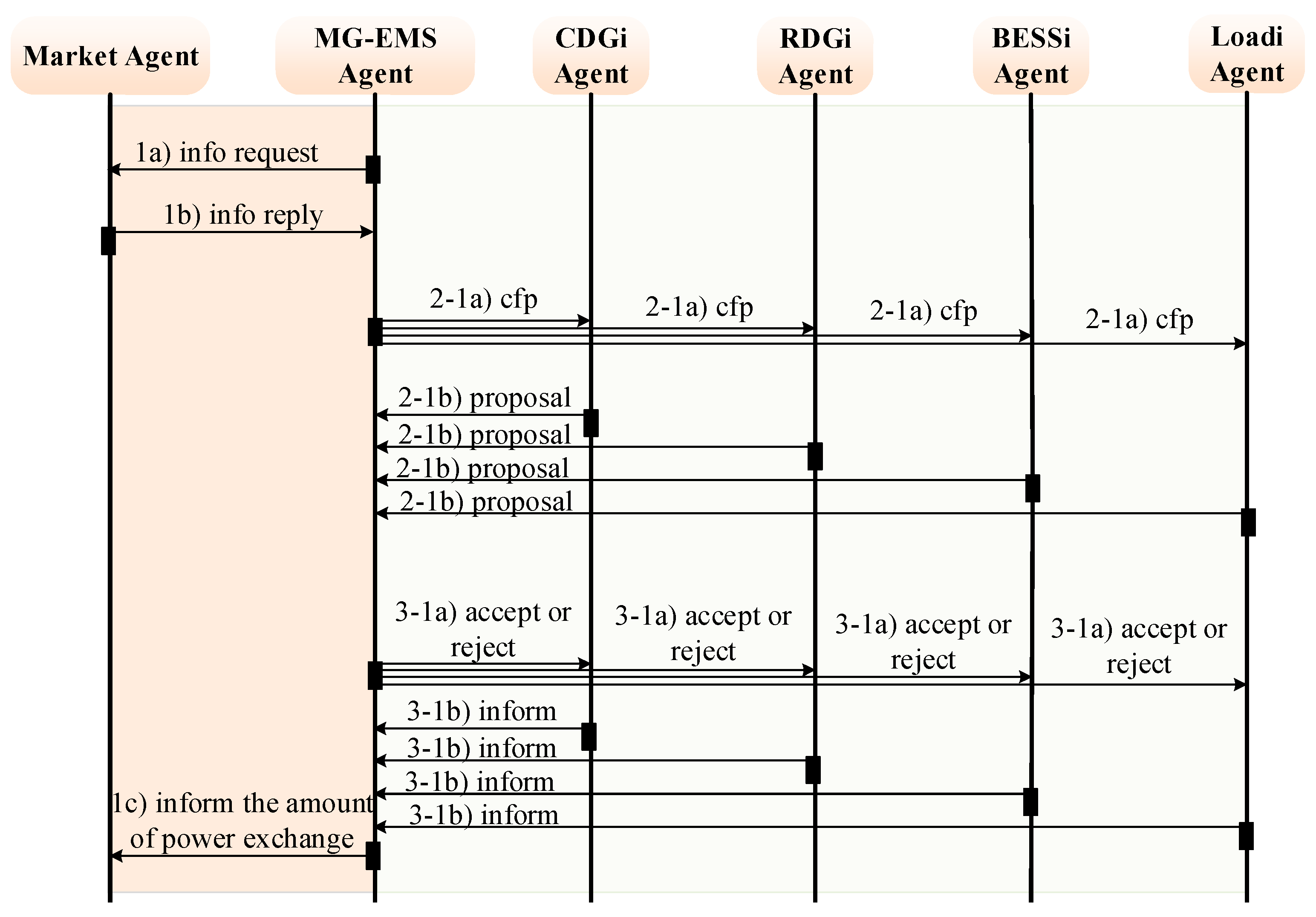
Figure 5.
State diagram of each agent in isolated part.
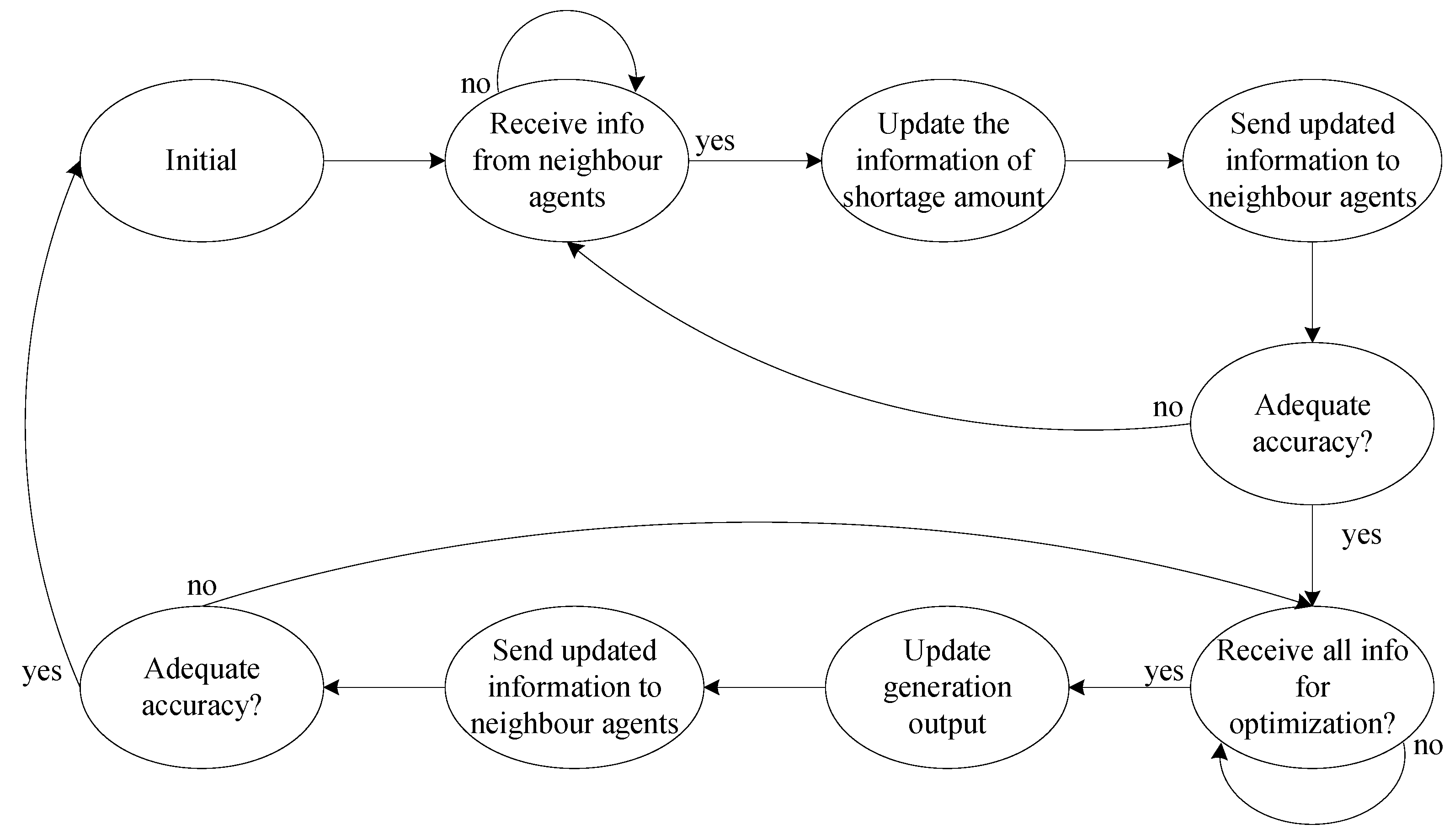
Figure 6.
Scheduling horizons of different operation modes of the proposed microgrid.
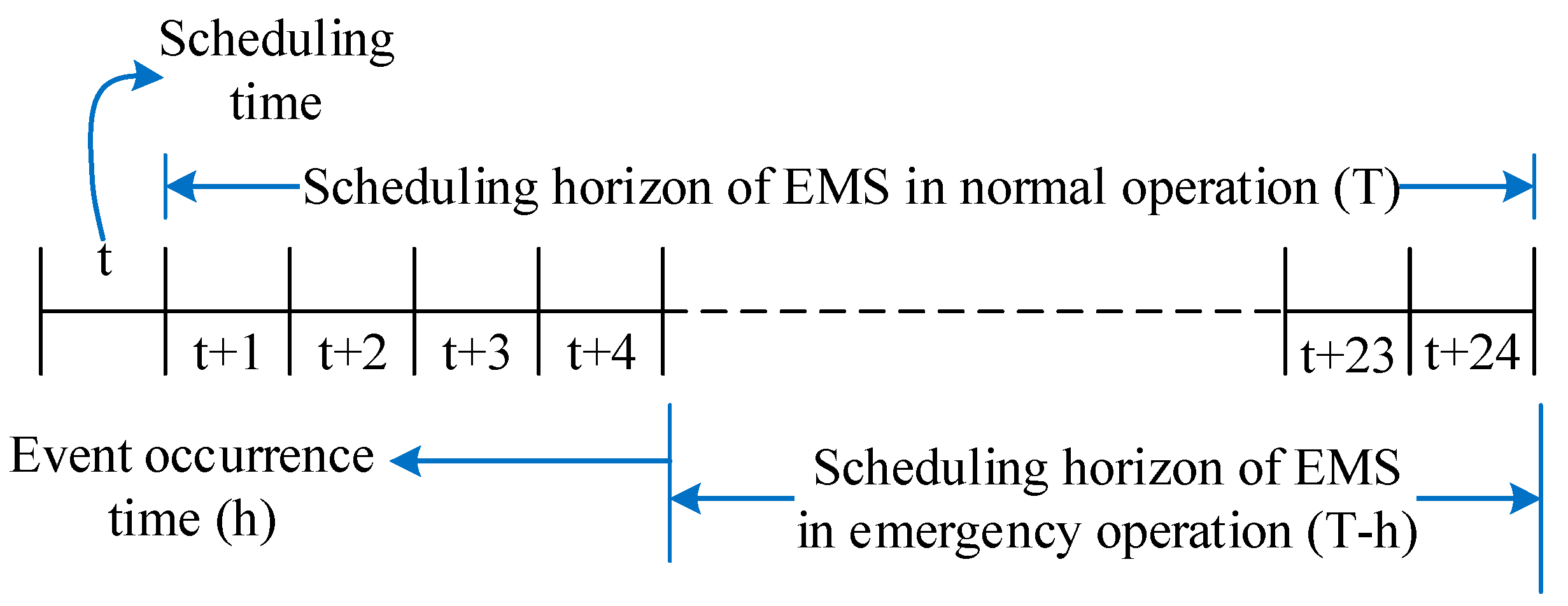
Figure 7.
Input data: (a) renewable generations; (b) load amount; and (c) market price signals.

Figure 8.
Piecewise linear generation cost of DG units.

Figure 9.
Operation results of normal case: (a) output power of DG units; (b) the amount of exchanging power; and (c) the charging/discharging amount and the SOC of BESS.
Figure 9.
Operation results of normal case: (a) output power of DG units; (b) the amount of exchanging power; and (c) the charging/discharging amount and the SOC of BESS.

Figure 10.
Case 1: Simulated scenario for evaluating proposed strategy during emergency mode operation.
Figure 10.
Case 1: Simulated scenario for evaluating proposed strategy during emergency mode operation.
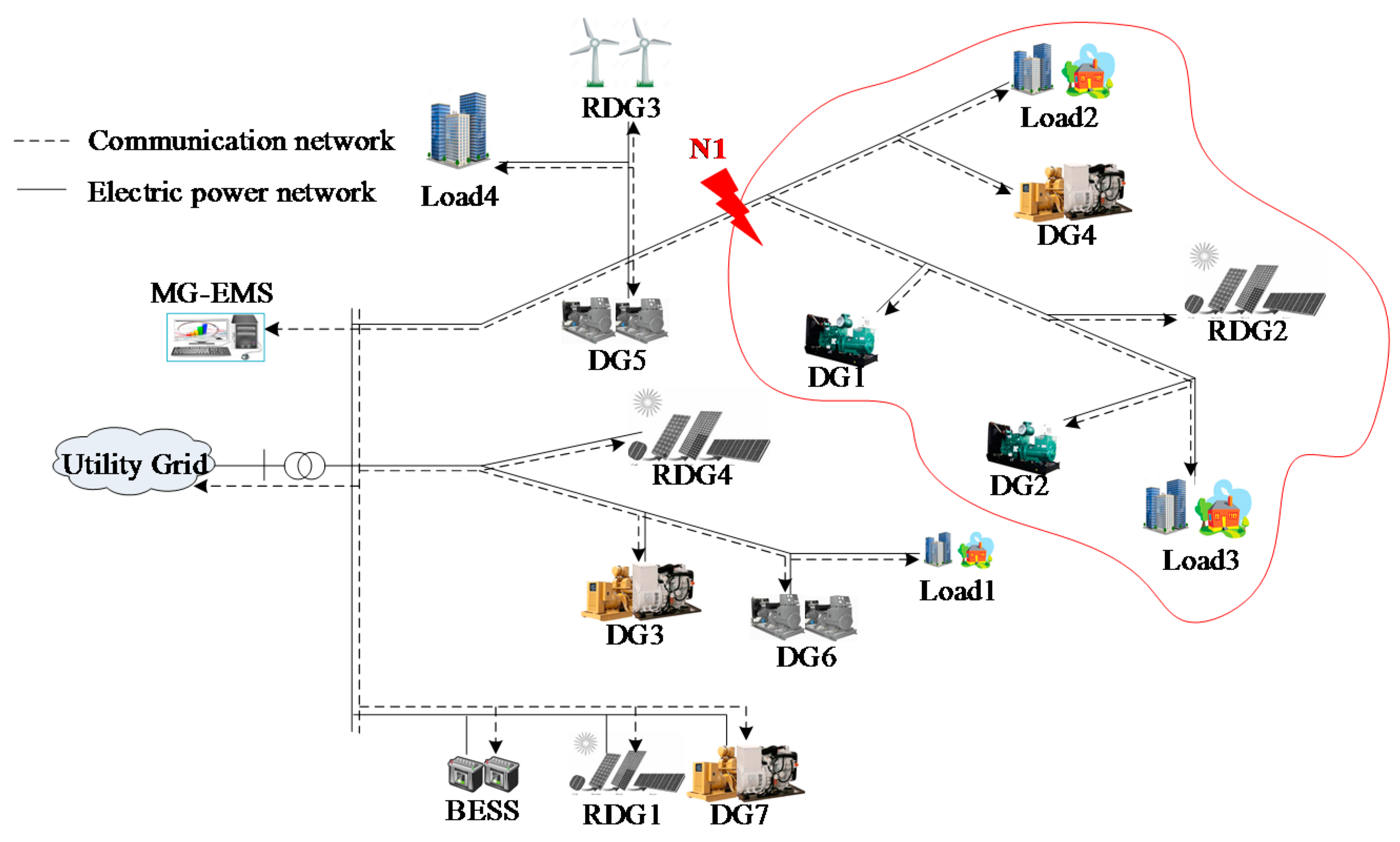
Figure 11.
Operation results of normal part: (a) output power of DG units; (b) the amount of exchanging power; and (c) the charging/discharging amount and the SOC of BESS.
Figure 11.
Operation results of normal part: (a) output power of DG units; (b) the amount of exchanging power; and (c) the charging/discharging amount and the SOC of BESS.

Figure 12.
Operation results of power failure part for remaining intervals (rescheduling by MG-EMS): (a) output power of DG units; and (b) load shedding amount.
Figure 12.
Operation results of power failure part for remaining intervals (rescheduling by MG-EMS): (a) output power of DG units; and (b) load shedding amount.
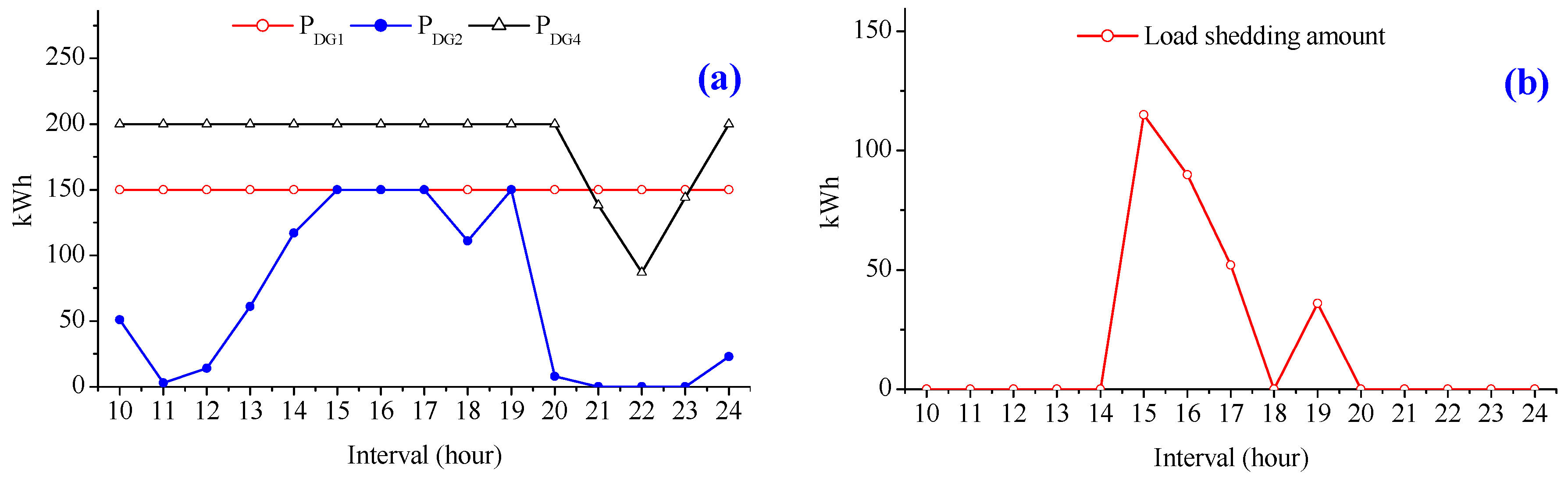
Figure 13.
Operation results of isolated part at interval 10: (a) information sharing (shortage amount); and (b) distributed optimization.
Figure 13.
Operation results of isolated part at interval 10: (a) information sharing (shortage amount); and (b) distributed optimization.

Figure 14.
Operation results of isolated part for remaining intervals: (a) output power of DG units; and (b) load shedding amount.
Figure 14.
Operation results of isolated part for remaining intervals: (a) output power of DG units; and (b) load shedding amount.

Figure 15.
Case 2: Simulated scenario for evaluating proposed strategy during emergency mode operation.
Figure 15.
Case 2: Simulated scenario for evaluating proposed strategy during emergency mode operation.

Figure 16.
Operation results of normal part: (a) output power of DG units; and (b) the amount of exchanging power.
Figure 16.
Operation results of normal part: (a) output power of DG units; and (b) the amount of exchanging power.

Figure 17.
Operation results of isolated part at interval 15: (a) information sharing (shortage amount); (b) distributed optimization; (c) the output power of DG units for remaining intervals; and (d) the output power of DG units for remaining intervals (rescheduling by MG-EMS).
Figure 17.
Operation results of isolated part at interval 15: (a) information sharing (shortage amount); (b) distributed optimization; (c) the output power of DG units for remaining intervals; and (d) the output power of DG units for remaining intervals (rescheduling by MG-EMS).

Figure 18.
Operation results of isolated part using consensus algorithm: (a) Case 1; and (b) Case 2.
Figure 18.
Operation results of isolated part using consensus algorithm: (a) Case 1; and (b) Case 2.


Table 1.
Parameters related to DG units and BESS of the microgrid system.
| Parameters | DG 1 | DG 2 | DG 3 | DG 4 | DG 5 | DG 6 | DG 7 |
|---|---|---|---|---|---|---|---|
| Min. | 0 | 0 | 0 | 0 | 0 | 0 | 0 |
| Max. | 150 | 150 | 100 | 200 | 200 | 150 | 100 |
| a | 561 | 310 | 300 | 561 | 310 | 300 | 570 |
| b | 7.92 | 7.88 | 7.9 | 7.92 | 7.85 | 7.9 | 7.98 |
| c | 0.00125 | 0.00194 | 0.00198 | 0.00125 | 0.002 | 0.0025 | 0.0014 |
Table 2.
The comparison for applying consensus algorithm and diffusion strategy.
| Parameters | Case 1 | Case 2 | ||
|---|---|---|---|---|
| Consensus Algorithm | Diffusion Strategy | Consensus Algorithm | Diffusion Strategy | |
| The number of agents | 6 | 6 | 4 | 4 |
| The number of iterations | 1900 | 49 | 1250 | 30 |
| Calculation time (s) | 0.16 | 0.11 | 0.14 | 0.1 |
| Reduction of iteration (%) | 0 | 97.4 | 0 | 97.6 |
| Reduction of calculation time (%) | 0 | 31.25 | 0 | 28.6 |
© 2017 by the authors. Licensee MDPI, Basel, Switzerland. This article is an open access article distributed under the terms and conditions of the Creative Commons Attribution (CC BY) license (http://creativecommons.org/licenses/by/4.0/).
Share and Cite
MDPI and ACS Style
Bui, V.-H.; Hussain, A.; Kim, H.-M. Diffusion Strategy-Based Distributed Operation of Microgrids Using Multiagent System. Energies 2017, 10, 903. https://doi.org/10.3390/en10070903
AMA Style
Bui V-H, Hussain A, Kim H-M. Diffusion Strategy-Based Distributed Operation of Microgrids Using Multiagent System. Energies. 2017; 10(7):903. https://doi.org/10.3390/en10070903
Chicago/Turabian StyleBui, Van-Hai, Akhtar Hussain, and Hak-Man Kim. 2017. "Diffusion Strategy-Based Distributed Operation of Microgrids Using Multiagent System" Energies 10, no. 7: 903. https://doi.org/10.3390/en10070903
Note that from the first issue of 2016, this journal uses article numbers instead of page numbers. See further details here.