Nonlinear Synergetic Governor Controllers for Steam Turbine Generators to Enhance Power System Stability


1
State Key Laboratory of Advanced Electromagnetic Engineering and Technology, Huazhong University of Science and Technology, 1037 Luoyu Road, Wuhan 430074, China
2
College of Electrical Engineering & New Energy, China Three Gorges University, 8 College Road, Yichang 443002, China
*
Author to whom correspondence should be addressed.
Energies 2017, 10(8), 1092; https://doi.org/10.3390/en10081092
Submission received: 22 June 2017
/
Revised: 17 July 2017
/
Accepted: 24 July 2017
/
Published: 26 July 2017
(This article belongs to the Section F: Electrical Engineering)
Abstract
:This paper proposes a decentralized nonlinear synergetic governor controller (NSGC) for turbine generators to enhance power system stability by using synergetic control theory and the feedback linearization technique. The precise feedback linearization model of a turbine-generator with a steam valve control is obtained, at first, by using a feedback linearization technique. Then based on this model, a manifold is defined as a linear combination of the deviation of the rotor angle, speed deviation, and speed derivative. The control law of the proposed NSGC is deduced and the stability condition of the whole closed-loop system is subsequently analyzed. According to the requirement of the primary frequency regulation, an additional proportional integral (PI) controller is designed to dynamically track the steady-state value of the rotor angle. Case studies are undertaken based on a single-machine infinite-bus system and the New England system, respectively. Simulation results show that the proposed NSGC can suppress the power oscillations and improve transient stability more effectively in comparison with the conventional proportional-integral-derivative (PID) governor controller. Moreover, the proposed NSGC is robust to the variations of the system operating conditions.
1. Introduction
Maintaining the stability of the power system under various disturbances is one of the critical issues of concern for the power operators, especially for the power system integration of bulk renewable energy [1,2,3,4,5,6,7]. One of the most traditional methods to improve the stability of the power system under both small and large disturbances is through designing advanced controllers for the excitation system [8,9,10,11,12,13]. However, due to the limitation of the maximum exciting current, the improvement of the transient stability made by excitation regulation is limited. In addition to the excitation controls, the inherent governor torque-speed characteristic was recognized as an important contributor to the damping of system oscillations [14]. A properly-tuned governor can provide better overall damping of the system oscillations together with increased system robustness [15,16,17,18,19]. With the replacement of the electro-hydraulic governor to the mechanical hydraulic speed control system, the response speed of the speed governor is improved to the same level of the excitation system. This gives the governor control the potential for improving the power system stability with respect to small and large disturbances.
Conventional proportional-integral-derivative (PID) governor controller design based on a specific operating condition cannot always guarantee providing satisfactory performance over a wide range of operating conditions. References [20,21] indicate that the stability region not only depends upon the turbine operating point, but also the network parameters, whose variation can result in instability of the power system. Many references have aimed at this issue using nonlinear approaches, such as robust optimal control theory [22], Lyapunov’s direct method [23], the feedback linearization approach [24], and neural networks [25,26]. In [27], differential geometric theory is applied to nonlinear steam-valve control and the control law obtained is implemented by a purely local feedback signal. In [22], an optimal robust governor is designed by taking into account uncertainties explicitly caused by the nonlinear characteristics of the turbine. This approach will guarantee the stability and the performance of the speed control loop for the entire turbine operating range. However, the effect of interconnected system parameter changes is not considered. In [25], two separate continually online-trained neurocontrollers for excitation and turbine control of a turbo-generator are designed to replace the conventional automatic voltage regulator and the turbine governor of a generator. However, training a network to handle the parameter changes not encountered a priori requires time. These nonlinear controllers for turbine governors can suppress the oscillation and improve the system stability, but most of them only consider the speed adjustment regardless of the power regulation.
In recent years, the synergetic control theory based on modern mathematics and synergetics has been employed in designing controller for nonlinear systems [28]. This has the advantages of order reduction, similar to sliding mode control, but without the disadvantages of chattering [29]. The synergetic control approach provides a continuous control law driving system states to a predesigned attractor and onto the operating equilibrium point. A nonlinear system using synergetic control can hold the global stability of a manifold, and the synergetic controller is easily implemented in practice. The synergetic control has been successfully applied in designing controllers for power electronics devices [30,31] and generators [32,33,34,35,36,37,38,39]. A decentralized synergetic damping controller, which employs reinforcement learning to update the controller parameters online in order to improve the damping performance, is proposed for a multi-machine system in [33]. In [35,36,37], an adaptive fuzzy power system stabilizer based on synergetic control theory is designed, in which fuzzy logic systems are used to approximate the unknown system dynamics. In [39], a decentralized synergetic excitation controller for synchronous generators is designed to enhance the transient stability and obtain a satisfactory voltage regulation performance of power systems. Since the synergetic control can provide asymptotic stability, these synergetic controllers have excellent performance in damping oscillations for power systems. However, the application of synergetic control theory in steam turbine governing control is not reported.
In this paper, a nonlinear synergetic governor controller (NSGC) for turbine generators is proposed to enhance power system stability by using synergetic control theory and the feedback linearization technique. Meanwhile, the stability condition of the closed-loop system is analyzed and the proposed NSGC can provide asymptotic stability and improve transient stability. The feedback linearization method is used to achieve the precise feedback linearization model of a generator with steam valve control, firstly. Then, based on this model, a linear combination of rotor angle deviation, speed deviation, and the speed derivative is selected as the manifold. According to the synergetic control theory, the control law of the proposed NSGC can be deduced through control synthesis. The stability and its condition of the closed-loop system are also analyzed. Considering the requirement of primary frequency regulation, an additional proportional integral (PI) controller is designed to dynamically track the steady-state value of the rotor angle. Finally, case studies are undertaken based on a single-machine infinite-bus system and the New England system to verify the effectiveness of the propose NSGC, respectively.
2. Synergetic Control Theory
Synergetic control theory uses the nonlinearity of the system itself to provide an effective means for the design of the nonlinear system feedback controller. The design process can be introduced as follows: consider an n-dimensional nonlinear dynamic system, which can be described as the following differential equation [27,28,29,30,31,32]:
where x represents the system state vector, u is the control input vector, and t is time.
The design of a synergetic controller usually begins with a selection of a function of the system state variables, called the macro-variable, which can be expressed as ψ(x,t). The macro-variable should be defined according to the control objectives and performance requirements.
By using the synergetic controller, the system state variables x will be forced to evolve on the manifold ψ = 0, and the desired dynamic evolution of the macro-variables is:
where T is a positive constant that indicates the converging speed to the manifold specified by the macro-variable. Differentiating the macro-variable ψ(x,t) along Equation (1) leads to:
Combining Equations (1)–(3), the following equation can be obtained:
Solving Equation (4), the control law u can be obtained as:
Under the control of u, the closed-loop system converges to the manifold at a speed determined by T from any initial positions.
According to Equation (2), we can obtain the solution of the macro-variable:
Since T > 0, the macro-variable ψ will decay exponentially with a speed determined by T. The smaller the value of T is, the faster the macro-variable decays. When ψ reaches zero, the system converges to the manifold and then operates on the manifold without leave. Therefore, the value of T should be much smaller than the system dynamic response time so that the macro-variable is on the manifold during most of the transient period. For a given desirable dynamic response time of the closed-loop system, the constant T should be chosen as its 1/300–1/30, which would lead to satisfactory control performance.
The manifold is a very important concept in synergetic control, which can be regarded as a constraint in the system state space domain and also an attractor of the closed-loop system. Suppose the macro-variable is selected as . The control law (Equation (5)) forces the state variable trajectory to satisfy Equation (2). According to this equation, the trajectory converges to manifold with a time constant and then stays on the manifold at all times.
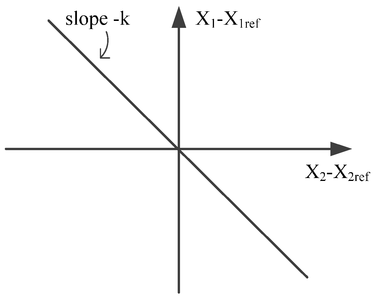
Equation (7) establishes a linear dependence between the two state variables x1 and x2, which can be represented as a straight line with slope-k, as shown in Figure 1. The system operating point converges to the straight line (the control manifold) and then moves along it to the origin (steady state).
3. Design of Nonlinear Synergetic Governor Controller for Steam Turbine Generators
3.1. Mathematical Model of the Turbine Speed Governor System
Assume that the generator excitation regulator is well controlled; thus, the q-axis transient electromotive force can remain unchanged through the entire dynamic process. The synchronous generator can be described as follows [29]:
where δ is the rotor angle, ω is the rotor speed, ω0 is the synchronous speed, Pm and Pe are the mechanical input power and the electromagnetic power of the generator respectively, H is the generator inertia time constant, and D is the damping coefficient of the generator.
Generally, large-capacity turbo-generator units use turbines with intermediate reheaters. Only considering the high pressure control valve, and regardless of fast valving, the turbine system with an intermediate reheater can be described as:
where ; PH is the mechanical power made by the high-pressure cylinder; TH and THg are the time constant of the high-pressure cylinder and the high-pressure main regulating valve oil engine, respectively; CH is the high-pressure cylinder power distribution coefficient, about 0.3; u is the control input of the steam valve. Cml is the equivalent power weighting coefficient of the medium/low-pressure cylinders, about 0.7; and Pm0 is the initial value of mechanical power.
From Equations (8) and (9), the state equation of the turbine generator with steam valving control can be described as:
This can be rewritten in the form of matrices:
where:
3.2. Design of the NSGC for a Single-Machine Infinite-Bus Power System
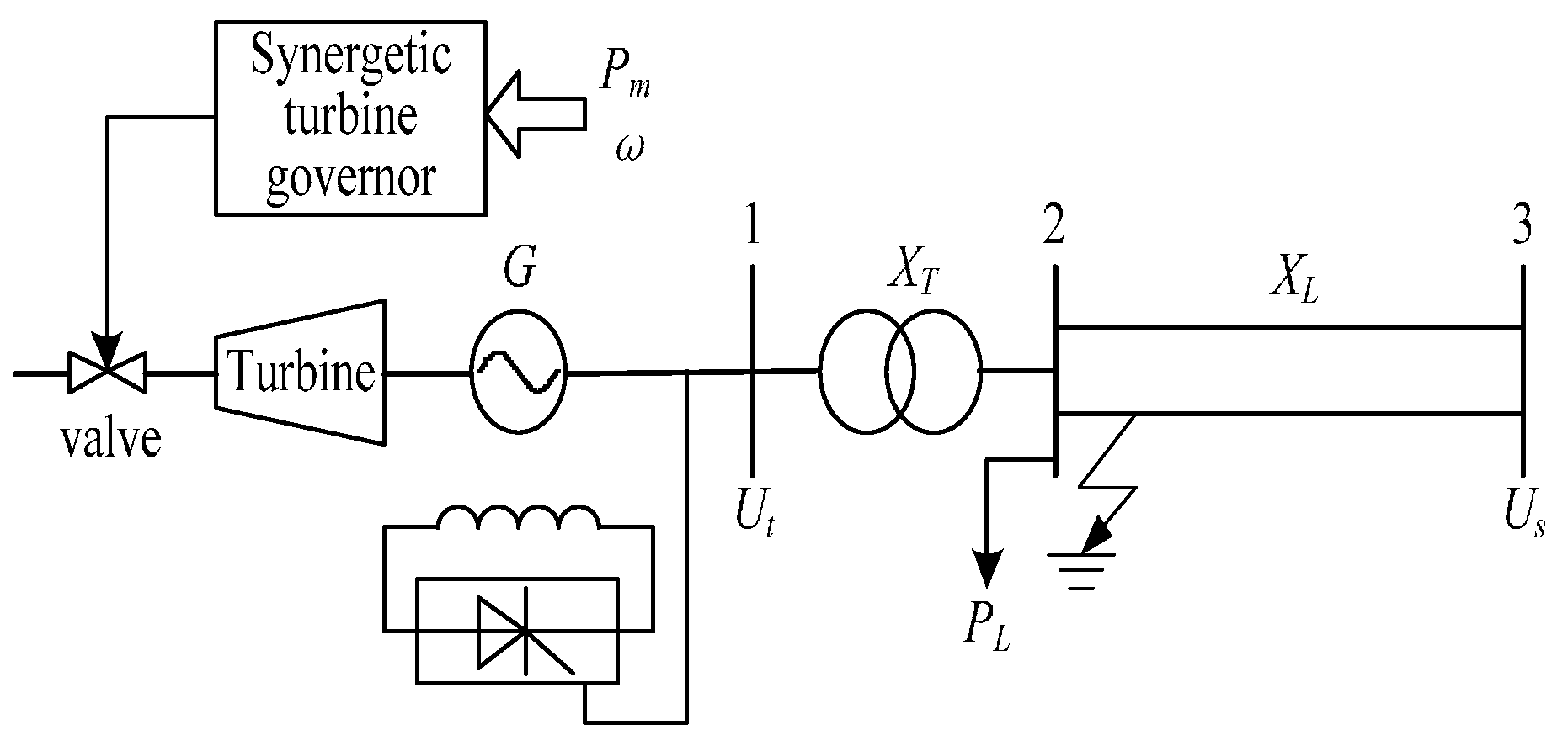
Considering a single-machine infinite-bus power system, as shown in Figure 2, the turbine generator with steam valve control can be described as shown in Equation (10). According to the feedback linearization theory, it can be completely linearized [1] and the coordinate transformation is defined as:
The transformed linear system is:
where:
When the disturbance occurs, the main goal of the steam valve controller is to keep the speed constant and to stabilize the rotor angle at the equilibrium point, i.e., δ = δe, ω = ωe = ω0. In order to obtain good performance in generator speed regulation and suppress the rotor angle oscillation, the linear combination of the rotor angle deviation, speed deviation, and speed acceleration can be selected as a macro variable, and shown as follows:
Substituting Equation (15) into (2), we have:
Then substituting Equation (13) into (16):
Substituting Equation (17) into (14), the control law of synergetic turbine governor can be obtained as:
From Equation (17), we can find that the derived synergetic control law is the full state feedback for a linear system if the linear combination of the state variables are used to form the manifold, and the feedback gain of each state variable is determined by the time constant T and the defined manifold parameters.
When the equilibrium point of the system changes after the disturbance, if the rotor angle reference value δe is kept constant, the active power output from the generator will change and deviate significantly from the active power value before the disturbance. In order to maintain the output active power of the generator in disturbance, a PI regulator can be designed to adjust the rotor angle reference δe dynamically according to the deviation of the active power of the machine. In this way, the rotor angle will follow the reference value δe to make active power deviation zero. However, grid generators generally need to participate in primary frequency modulation, and the relation between the rotor speed and active power in steady state can be described as:
Therefore, according to the comprehensive error generated by Equation (19), the PI regulator is designed as:
where KG is the unit power regulation, here the value is 25. Since the PI controller is only used to adjust the output power of the generator at steady state, its parameter should be adjusted to make δe change slowly, so as to smooth the adjustment. In the simulation, is selected as 0.05, and is selected as 0.2.
Since the system is in a steady state before the disturbance, the rotor angle can be expressed as:
According to Equations (20) and (21), we have:
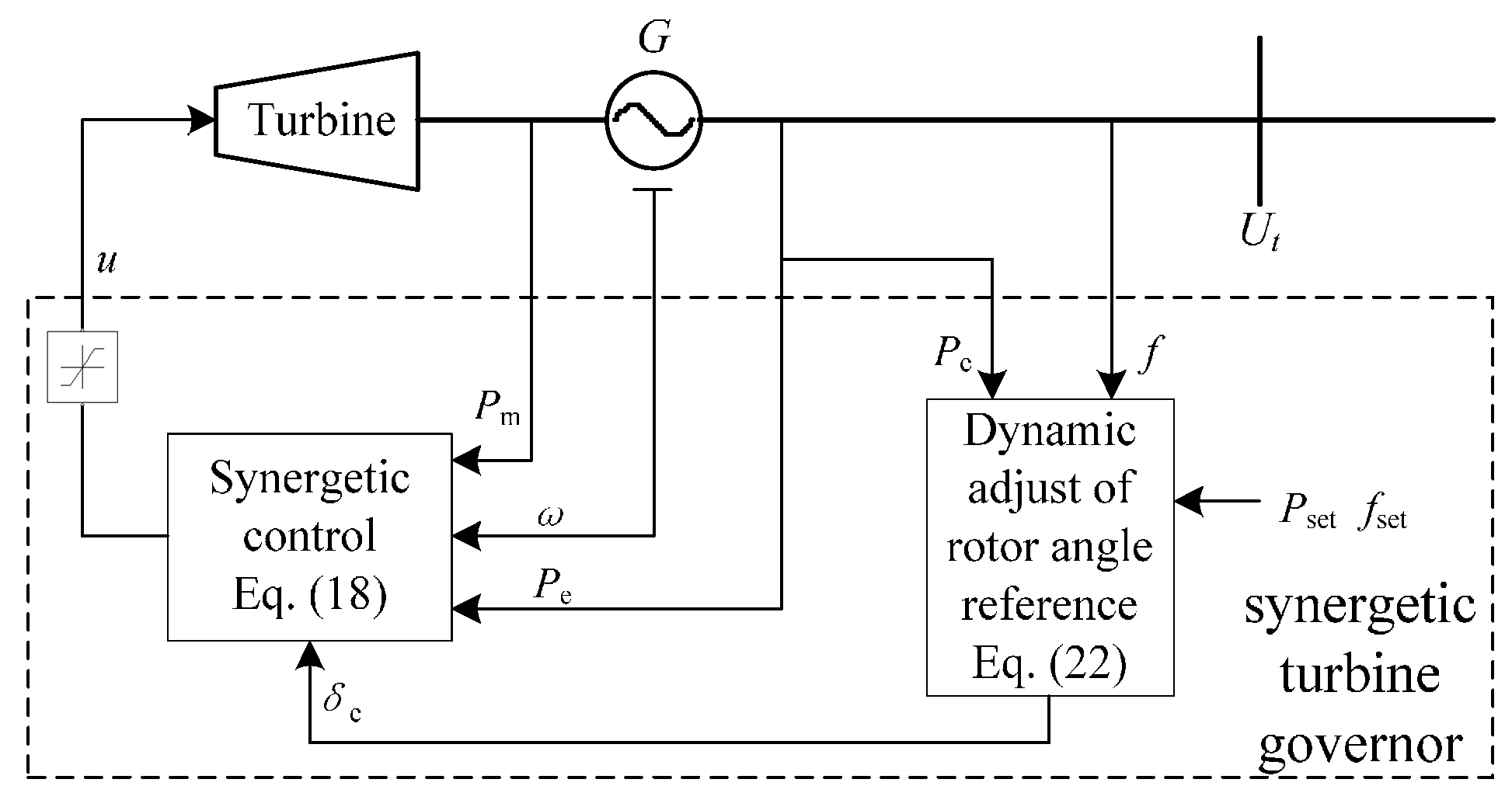
Equations (18), (20) and (22) together constitute a non-linear synergetic turbine governor, whose structure is shown in Figure 3.
By making the following coordinate transformation:
The feedback linearized system model Equation (13) is transformed into:
The macro variable in Equation (15) is converted to:
Under the control of Equation (18), the system will converge from any initial state to the manifold:
Operating on this manifold, the closed-loop control system can be described as a reduced-order dynamic system:
Substituting Equation (26) into (27), we can obtain:
The characteristic equation of the linear system represented by Equation (28) is:
According to the Lyapunov theory, the stable condition of the closed-loop system can be derived from Equation (29):
Thus, when the inequality Equation (30) and T > 0 are satisfied, the closed-loop system is asymptotically stable under the synergetic control.
3.3. Design of the Synergetic Turbine Governor for a Multi-Machine Power System
The dynamic model of an n-machine power system can be described as follows [24]:
Only considering the high-pressure control valve, the steam regulating system can be described as:
where i = 1, 2, ⋅⋅⋅, n, denote the i-th generator. Applying the feedback linearization method to the nonlinear system represented by Equations (31) and (32), the linearized system is obtained:
where:
The coordinate transform is:
Each generator is considered as a subsystem. For each subsystems, a manifold is defined as:
Using the same design process as the single machine system, the control law of each synergetic turbine governor can be obtained as:
From Equation (37), it can be seen that the inputs of the controller are local measurements and do not need any information of the power transmission network. Thus, the synergetic turbine governor has good adaptability to the variations of the transmission network topology.
Taking into account the primary frequency regulation, PI regulators can be designed to adjust the reference δei of each generator rotor angle using the same method in the previous section. The PI regulator can be described as follows:
Equations (37) and (38) constitute the nonlinear synergetic turbine governor, whose structure is the same as that of the single-machine infinite-bus power system shown in Figure 3.
From the multi-machine power system model described in Equations (31) and (32), it can be seen that generators are coupled with each other by electromagnetic power. As long as the asymptotic stability of the subsystems is ensured, the whole system is asymptotically stable, and the stability of each subsystem has been analyzed in the above-mentioned stand-alone infinite system, so the stability conditions of the entire system are:
However, the control output is limited in the actual control system. When the output reaches the maximum limit, the controller will not be able to make the subsystem converge to the manifold. Thus, the system may lose stability.
4. Case Studies
In this paper, case studies are carried out based on a single-machine infinite-bus power system and New England power system in MATLAB/Simulink, respectively. To verify the effectiveness of the proposed NSGC, the simulation results of the conventional PID turbine governor are also provided for comparison.
4.1. Single-Machine Infinite-Bus Power System
A single-machine infinite-bus power system shown in Figure 2 is used as the first case study. The generator is represented as a third-order model and a PID excitation regulator is used for it. The parameters of this system are given as follows, = 4 s, xd = 1.2 pu, pu, xT = 0.11 pu, xL = 0.24 pu, H = 4 s, D = 2, = 0.7 s, CH = 0.3, Cml = 0.7. The initial conditions are: δ0 = 33.5°, = 1.0 pu, = 1.05 pu.
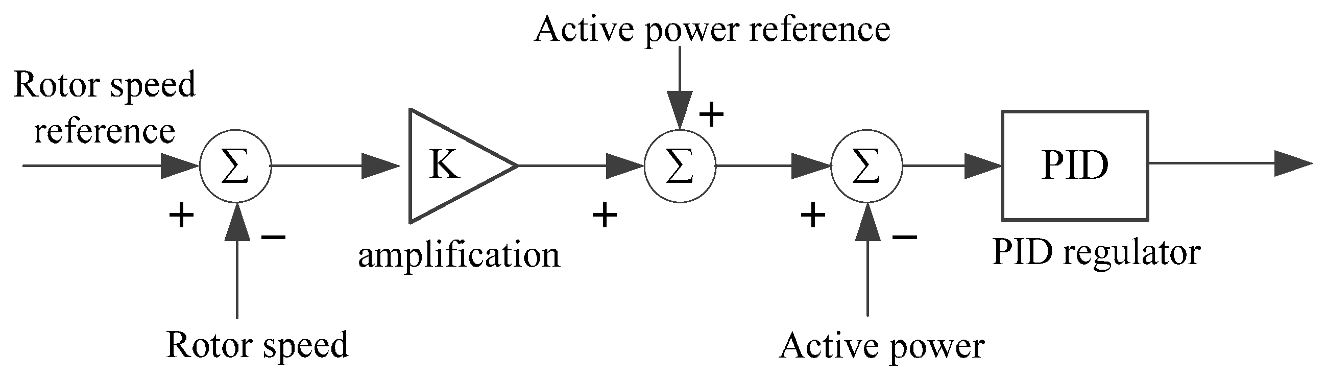
The typical block diagram of conventional PID turbine governor is shown in Figure 4 and its parameters are given as Kp = 0.2, Ki = 2.85, Kd = 0.83, which are optimized by the differential evolution algorithm. The parameters of the NSGC are selected as k1 = 1.5, k2 = 0.02, T = 0.05 s. Two types of disturbances are considered in the simulation: a three-phase short-circuit fault and a load disturbance.
In this case, a three-phase short-circuit fault occurs in the start terminals of the transmission line at 1.0 s, and then one of the parallel transmission lines is switched off at 1.1 s, and the fault line recloses successfully at 1.7 s. The system responses to a three-phase short-circuit fault are shown in Figure 5. It can be seen that the maximum value of the rotor angle is smaller and the oscillation is weaker under the control of the NSGC than that of the PID governor. Figure 5e depicts the mechanical power, which is controlled by the turbine controller. The larger amplitude of the swing in the mechanical power indicates that the output of the NCGC is stronger than that of the PID controller.
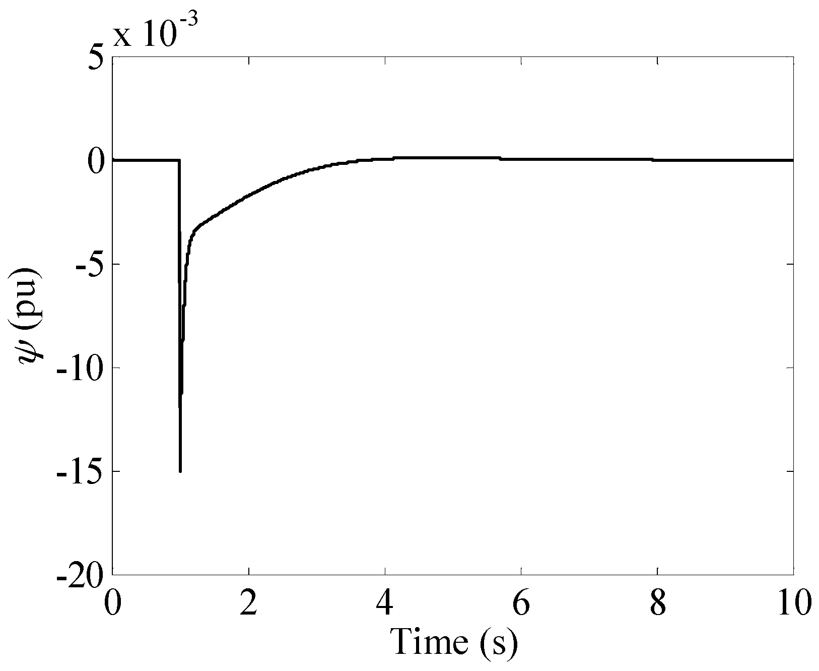
The system responds to a 10% step change of the mechanical power is shown in Figure 6. It can be found that the system equilibrium point changes after the disturbance occurs. The rotor angle reaches its new steady value smoothly under the control of the NSGC, while there is an obvious oscillation under the control of PID governor. Figure 7 shows the response of the macro-variable. It can be seen that the macro-variable decays quickly after the disturbance occurs and then, due to the rotor angle reference adjustment by the PI regulator, it maintains a smaller value until the system approaches the equilibrium point.
These simulation results demonstrate that the proposed NSGC can dampen the oscillation more effectively compared with conventional PID governor under large, as well as small, disturbances.
4.2. New England System
In this subsection, the New England system [40,41,42,43,44] shown in Figure 8 is applied to demonstrate the effectiveness of the NSGC in a multi-machine power system. All the loads are considered as the constant impedance model. The parameters of the NSGC for each generator are chosen to be k1 = 1.5, k2 = 0.02, T = 0.2 s. The parameters of the conventional PID governor are chosen to be Kp = 0.2, Ki = 3, Kd = 2.5.
For a large disturbance, a three-phase short-circuit fault is applied at the line 3–4 near the bus 3 at 1 s and then the fault line is switched off at 1.1 s. At 1.6 s, line 3–4 recloses successfully. In order to verify the robustness of the proposed NSGC, two operating conditions shown in Table 1 are considered in the simulation.
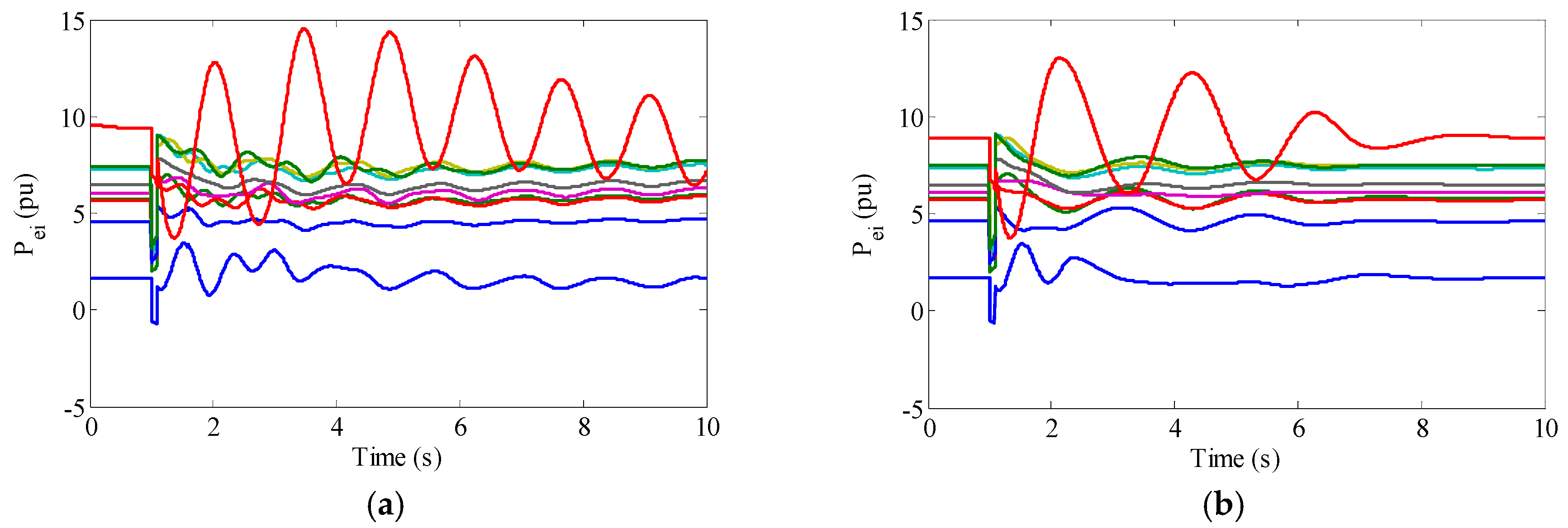
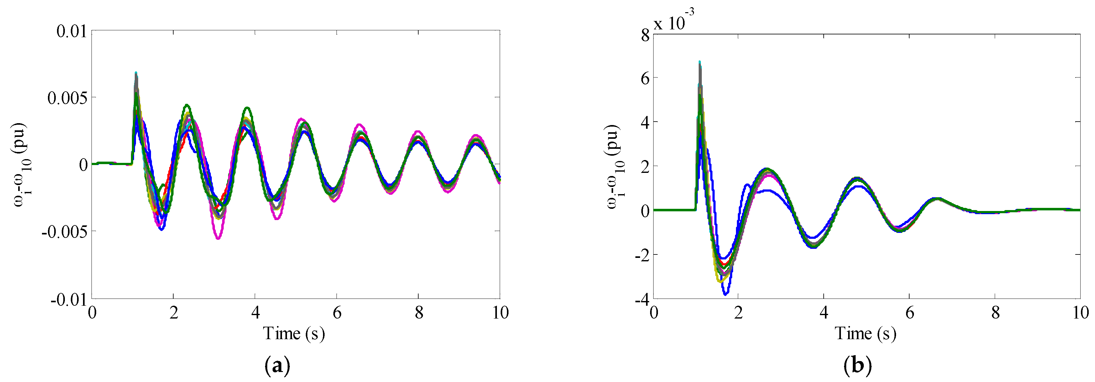
The responses of the electrical power, relative rotor angle, and relative speed to a three-phase short-circuit fault under operating condition 1 are shown in Figure 9, Figure 10 and Figure 11. Since the tenth generator is an external equivalent generator, bus 39 can be regarded as an infinite bus with a low impedance. Thus, only the relative rotor angle and relative speed of the G10 relative to other generators are shown in Figure 10 and Figure 11. It can be seen from Figure 11 that there are synchronous oscillations between G1–G9 and G10. Under the control of PID governors, the oscillation attenuation is slow and the system is still not stable at the end of the simulation. While under the control of the NSGCs, the oscillations are coming to an end at 7 s and the system returns to the equilibrium point. From Figure 10, it can also be found that the proposed NSGC can reduce the amplitude of the first swing of the rotor angle and improve the transient stability of the system.
The responses to a three-phase short-circuit fault under operating condition 2 are shown in Figure 12, Figure 13 and Figure 14. It can be seen that the NSGC can still dampen the oscillation well when the operating condition is changed.
The simulation results show that the proposed NSGC can suppress the system oscillation and enhance the transient stability of the system. It also has excellent robustness in different operating conditions.
5. Conclusions
In this paper, a synergetic control theory-based nonlinear synergetic governor controller is proposed for turbine generators to enhance power system stability. With feedback linearization technology, the steam turbine generator model with steam valve control is precisely linearized. Based on this model and the control target, the linear combination of the rotor angle deviation, speed deviation, and speed acceleration are chosen to form a manifold. Then the control law of the proposed controller is deduced. Moreover, the stability condition of the closed-loop system is also analyzed. According to the requirement of primary frequency regulation, an additional PI controller is designed to dynamically track the steady-state value of the rotor angle. Case studies are undertaken based on a single-machine infinite-bus system and the New England system, respectively. The simulation results show that the proposed NSGC can suppress the power oscillations and improve the transient stability more effectively in comparison with the conventional PID governor. It is also robust to the variations of the operating conditions.
Acknowledgments
This work is supported by National Natural Science Foundation of China (51577075).
Author Contributions
Ping Zhao, Haishun Sun, Wei Yao, Jinyu Wen, and Xingbao Ju designed the nonlinear synergetic governor controllers; Ping Zhao, Wei Yao and Xingbao Ju provided the simulation platform and instructions for carrying out the simulation; and all authors discussed the results and contributed to writing the paper.
Conflicts of Interest
The authors declare no conflict of interest.
References
- Bai, F.; Liu, Y.; Liu, Y.; Sun, K.; Bhatt, N.; Rosso, A.D.; Farantatos, E.; Wang, X. A measurement-based approach for power system instability early warning. Prot. Control Mod. Power Syst. 2016, 1, 1–9. [Google Scholar] [CrossRef]
- Chen, J.; Jiang, L.; Yao, W.; Wu, Q.H. Perturbation estimation based nonlinear adaptive control of a full rate converter wind-turbine for fault ride-through capability enhancement. IEEE Trans. Power Syst. 2014, 29, 2733–2743. [Google Scholar] [CrossRef]
- Yang, B.; Jiang, L.; Wang, L.; Yao, W.; Wu, Q.H. Nonlinear maximum power point tracking control and modal analysis of DFIG based wind turbine. Int. J. Electr. Power Energy Syst. 2016, 74, 429–436. [Google Scholar] [CrossRef]
- Liu, J.; Wen, J.Y.; Yao, W.; Long, Y. Solution to short-term frequency response of wind farms by using energy storage systems. IET Renew. Power Gener. 2016, 10, 669–678. [Google Scholar] [CrossRef]
- Ma, Z.; Chen, H.; Chai, Y.L. Analysis of voltage stability uncertainty using stochastic response surface method related to wind farm correlation. Prot. Control Mod. Power Syst. 2017, 2, 20. [Google Scholar] [CrossRef]
- Liao, S.W.; Yao, W.; Han, X.N.; Wen, J.Y.; Cheng, S.J. Chronological operation simulation framework for regional power system under high penetration of renewable energy using meteorological data. Appl. Energy 2017, 203, 816–828. [Google Scholar] [CrossRef]
- Zhao, J.Q.; Zhang, Y.J.; Zhang, P.; Jin, X.M.; Fu, C. Development of a WAMS based test platform for power system real time transient stability detection and control. Prot. Control Mod. Power Syst. 2016, 1, 1–6. [Google Scholar] [CrossRef]
- Demello, F.P.; Concordia, C. Concepts of synchronous machine stability as affected by excitation control. IEEE Trans. Power Appar. Syst. 1969, 88, 316–329. [Google Scholar] [CrossRef]
- Yao, W.; Jiang, L.; Wen, J.Y.; Wu, Q.; Cheng, S.J. Wide-area damping controller for power system interarea oscillations: A networked predictive control approach. IEEE Trans. Control Syst. Technol. 2015, 23, 27–36. [Google Scholar] [CrossRef]
- Yao, W.; Jiang, L.; Fang, J.; Wen, J.Y.; Cheng, S.J. Decentralized nonlinear optimal predictive excitation control for multi-machine power systems. Int. J. Electr. Power Energy Syst. 2014, 55, 620–627. [Google Scholar] [CrossRef]
- Liu, C.; Cai, G.W.; Gao, J.W.; Yang, D.Y. Design of nonlinear robust damping controller for power oscillations suppressing based on backstepping-fractional order sliding mode. Energies 2017, 10, 676. [Google Scholar]
- Liu, Z.Q.; Yao, W.; Wen, J.Y. Enhancement of power system stability using a novel power system stabilizer with large critical gain. Energies 2017, 10, 449. [Google Scholar] [CrossRef]
- Jiang, L.; Yao, W.; Wu, Q.H.; Wen, J.Y.; Cheng, S.J. Delay-dependent stability for load frequency control with constant and time-varying delays. IEEE Trans. Power Syst. 2012, 27, 932–941. [Google Scholar] [CrossRef]
- Wang, H.F.; Hao, Y.S.; Hogg, B.W.; Yang, Y.H. Stabilization of power systems by governor-turbine control. Int. J. Electr. Power Energy Syst. 1993, 15, 351–360. [Google Scholar] [CrossRef]
- Milanovic, J.V. Damping of the low-frequency oscillations of the generator: Dynamic interactions and the effectiveness of the controllers. IEE Proc. Gener. Transm. Distrib. 2002, 149, 753–760. [Google Scholar] [CrossRef]
- Fuchs, E.F.; Masoum, M.A.S. Power Quality in Power Systems and Electrical Machines, 1st ed.; Academic Press: Cambridge, MA, USA, 2008; p. 638. [Google Scholar]
- Fuller, J.F.; Fuchs, E.F.; Roesler, D.J. Influence of harmonics on power system distribution protection. IEEE Trans. Power Deliv. 1988, 3, 546–557. [Google Scholar] [CrossRef]
- Caciotta, M.; Giarnetti, S.; Leccese, F.; Leonowicz, Z. Comparison between DFT, adpative window DFT and EDFT for power quality frequency spectrum analysis. In Proceedings of the International Symposium: Modern Electric Power Systems, Wroclaw, Poland, 20–22 September 2010. [Google Scholar]
- Giarnetti, S.; Leccese, F.; Leonowicz, Z. Methods for detection of sub-harmonics in power systems. In Proceedings of the 11th International Scientific Conference Electric Power Engineering, Brno, Czech Republic, 4–6 May 2010; pp. 421–426. [Google Scholar]
- Phi, D.T.; Bourque, E.J.; Thorne, D.H.; Hill, E.F. Analysis and application of the stability limits of a hydro-generating unit. IEEE Trans. Power Appar. Syst. 1981, 7, 3203–3212. [Google Scholar] [CrossRef]
- Thorne, D.H.; Hill, E.F. Field testing and simulation of hydraulic turbine governor performance. IEEE Trans. Power Appar. Syst. 1974, 4, 1183–1191. [Google Scholar] [CrossRef]
- Jiang, J. Design of an optimal robust governor for hydraulic turbine generating units. IEEE Trans. Energy Conv. 1995, 10, 188–194. [Google Scholar] [CrossRef]
- Jiang, H.; Cai, H.; Dorsey, J.F.; Qu, Z. Toward a globally robust decentralized control for large-scale power systems. IEEE Trans. Control Syst. Technol. 1997, 5, 309–319. [Google Scholar] [CrossRef]
- Wu, J.; Yokoyama, A.; Lu, Q.; Goto, M.; Konishi, H. Decentralised nonlinear equilibrium point adaptive control of generators for improving multimachine power system transient stability. IEE Proc. Gener. Transm. Distrib. 2003, 150, 697–708. [Google Scholar] [CrossRef]
- Venayagamoorthy, G.K.; Harley, R.G. Two separate continually online-trained neurocontrollers for excitation and turbine control of a turbogenerator. IEEE Trans. Ind. Appl. 2002, 38, 887–893. [Google Scholar] [CrossRef]
- Venayagamoorthy, G.K.; Harley, R.G.; Wunsch, D.C. Comparison of heuristic dynamic programming and dual heuristic programming adaptive critics for neurocontrol of a turbogenerator. IEEE Trans. Neural Netw. 2002, 13, 764–773. [Google Scholar] [CrossRef] [PubMed]
- Lu, Q.; Sun, Y. Nonlinear stabilizing control of multimachine systems. IEEE Trans. Power Syst. 1989, 4, 236–241. [Google Scholar] [CrossRef]
- Kolesnikov, A.; Veselov, G. Modern Applied Control Theory: Synergetic Approach in Control Theory (in Russian); TSURE Press: Moscow-Taganrog, Russia, 2000. [Google Scholar]
- Santi, E.; Monti, A.; Li, D.; Proddutur, K.; Dougal, R.A. Synergetic control for power electronics applications: A comparison with the sliding mode approach. J. Circuits Syst. Comput. 2004, 13, 737–760. [Google Scholar] [CrossRef]
- Jiang, Z.H.; Dougal, R.A. Synergetic control of power converters for pulse current charging of advanced batteries from a fuel cell power source. IEEE Trans. Power Electron. 2004, 19, 1140–1150. [Google Scholar] [CrossRef]
- Santi, E.; Monti, A.; Li, D.; Proddutur, K.; Dougal, R.A. Synergetic control for DC-DC boost converter: Implementation options. IEEE Trans. Ind. Appl. 2003, 39, 1803–1813. [Google Scholar] [CrossRef]
- de Dieu Nguimfack Ndongmo, J.; Kenné, G.; Nfah, E.M. Design of nonlinear synergetic controller for transient stabilization enhancement of DFIG in multimachine wind power systems. Energy Procedia 2016, 93, 125–132. [Google Scholar] [CrossRef]
- Ademoye, T.; Feliachi, A. Reinforcement learning tuned decentralized synergetic control of power systems. Electr. Power Syst. Res. 2012, 86, 34–40. [Google Scholar] [CrossRef]
- Zhao, P.; Yao, W.; Wang, S.R.; Wen, J.Y.; Cheng, S.J. Decentralized nonlinear synergetic power system stabilizers design for power system stability enhancement. Int. Trans. Electr. Energy Syst. 2014, 24, 1356–1368. [Google Scholar] [CrossRef]
- Bouchama, Z.; Essounbouli, N.; Harmas, M.N.; Hamzaoui, A.; Saoudi, K. Reaching phase free adaptive fuzzy synergetic power system stabilizer. Int. J. Electr. Power Energy Syst. 2016, 77, 43–49. [Google Scholar] [CrossRef]
- Bouchama, Z.; Harmas, M.N. Optimal robust adaptive fuzzy synergetic power system stabilizer design. Electr. Power Syst. Res. 2012, 83, 170–175. [Google Scholar] [CrossRef]
- Nechadi, E.; Harmas, M.N.; Hamzaoui, A.; Essounbouli, N. Type-2 fuzzy based adaptive synergetic power system control. Electr. Power Syst. Res. 2012, 88, 9–15. [Google Scholar] [CrossRef]
- Jiang, Z.H. Design of a nonlinear power system stabilizer using synergetic control theory. Electr. Power Syst. Res. 2009, 79, 855–862. [Google Scholar] [CrossRef]
- Zhao, P.; Yao, W.; Wen, J.Y.; Jiang, L.; Wang, S.R.; Cheng, S.J. Improved synergetic excitation control for transient stability enhancement and voltage regulation of power systems. Int. J. Electr. Power Energy Syst. 2015, 68, 44–51. [Google Scholar] [CrossRef]
- Yao, W.; Jiang, L.; Wen, J.Y.; Wu, Q.H.; Cheng, S.J. Wide-area damping controller of FACTS devices for inter-area oscillations considering communication time delays. IEEE Trans. Power Syst. 2014, 29, 318–329. [Google Scholar] [CrossRef]
- Fang, J.K.; Yao, W.; Chen, Z.; Wen, J.Y.; Cheng, S.J. Design of anti-windup compensator for energy storage-based damping controller to enhance power system stability. IEEE Trans. Power Syst. 2014, 29, 1175–1185. [Google Scholar] [CrossRef]
- Shen, Y.; Yao, W.; Wen, J.Y.; He, H.B.; Chen, W.B. Adaptive supplementary damping control of VSC-HVDC for interarea oscillation using GrHDP. IEEE Trans. Power Syst. 2017, in press. [Google Scholar] [CrossRef]
- Yao, W.; Jiang, L.; Fang, J.K.; Wen, J.Y.; Cheng, S.J.; Wu, Q.H. Adaptive power oscillation damping controller of superconducting magnetic energy storage device for interarea oscillations in power system. Int. J. Electr. Power Energy Syst. 2016, 78, 555–562. [Google Scholar] [CrossRef]
- Shen, Y.; Yao, W.; Wen, J.Y.; He, H.B. Adaptive wide-area power oscillation damper design for photovoltaic plant considering delay compensation. IET Gener. Transm. Distrib. 2017, in press. [Google Scholar] [CrossRef]
Figure 1.
Geometric interpretation of the manifold in the phase plane.
Figure 2.
Single-machine infinite-bus power system with synergetic turbine governor.

Figure 3.
Block diagram of the proposed NSGC.

Figure 4.
Transfer function block of the steam turbine governing system.

Figure 5.
Responses to a three-phase short-circuit fault. (a) Rotor angle response; (b) Rotor angular speed response; (c) Electrical power response; (d)Terminal voltage response; (e) Mechanical power response; (f) Reference change of the rotor angle.
Figure 5.
Responses to a three-phase short-circuit fault. (a) Rotor angle response; (b) Rotor angular speed response; (c) Electrical power response; (d)Terminal voltage response; (e) Mechanical power response; (f) Reference change of the rotor angle.
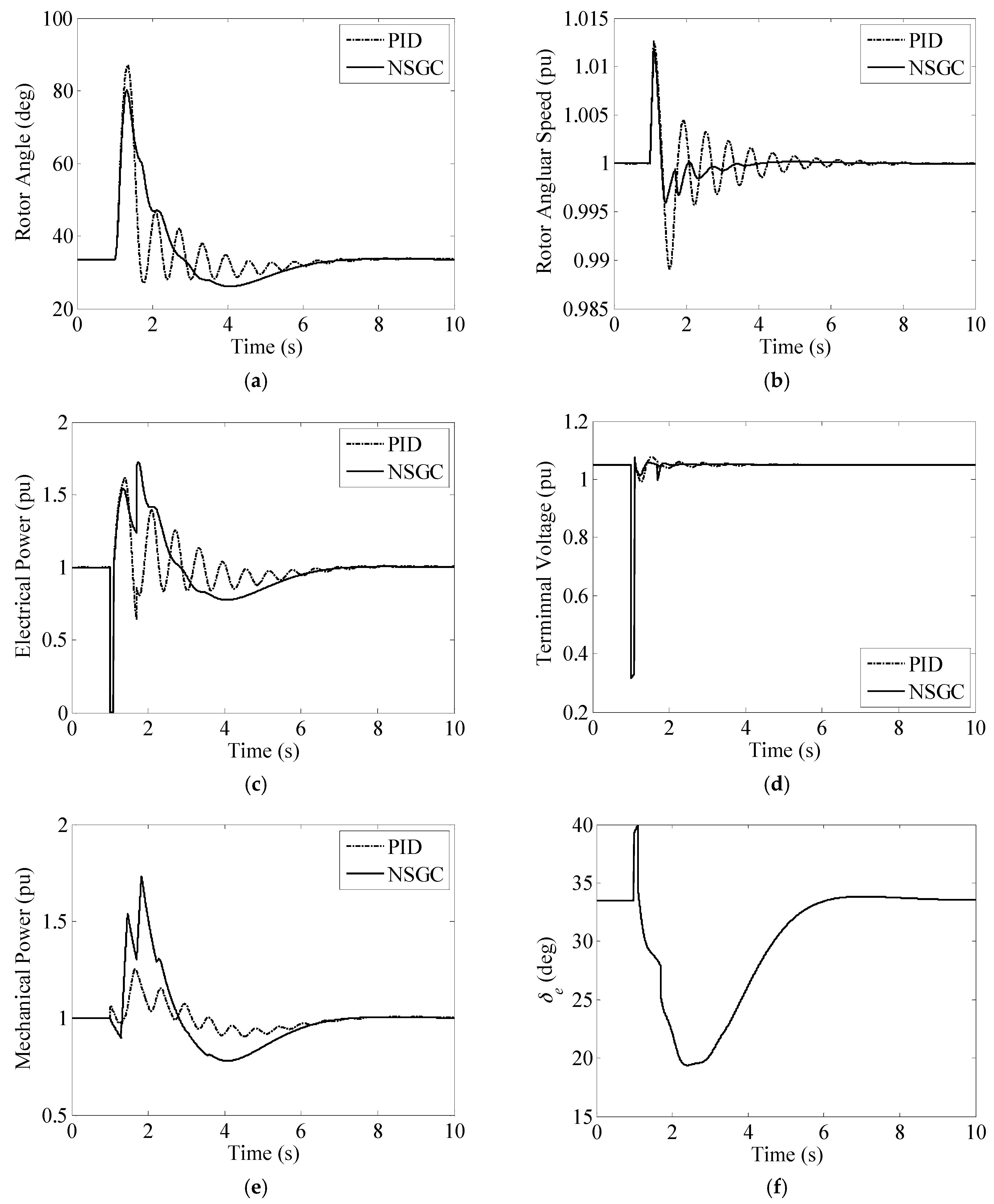
Figure 6.
Responses to a step change of the mechanical power. (a) Rotor angle response; (b) Rotor angular speed response; (c) Electrical power response; (d)Terminal voltage response; (e) Mechanical power response; (f) Reference change of the rotor angle.
Figure 6.
Responses to a step change of the mechanical power. (a) Rotor angle response; (b) Rotor angular speed response; (c) Electrical power response; (d)Terminal voltage response; (e) Mechanical power response; (f) Reference change of the rotor angle.
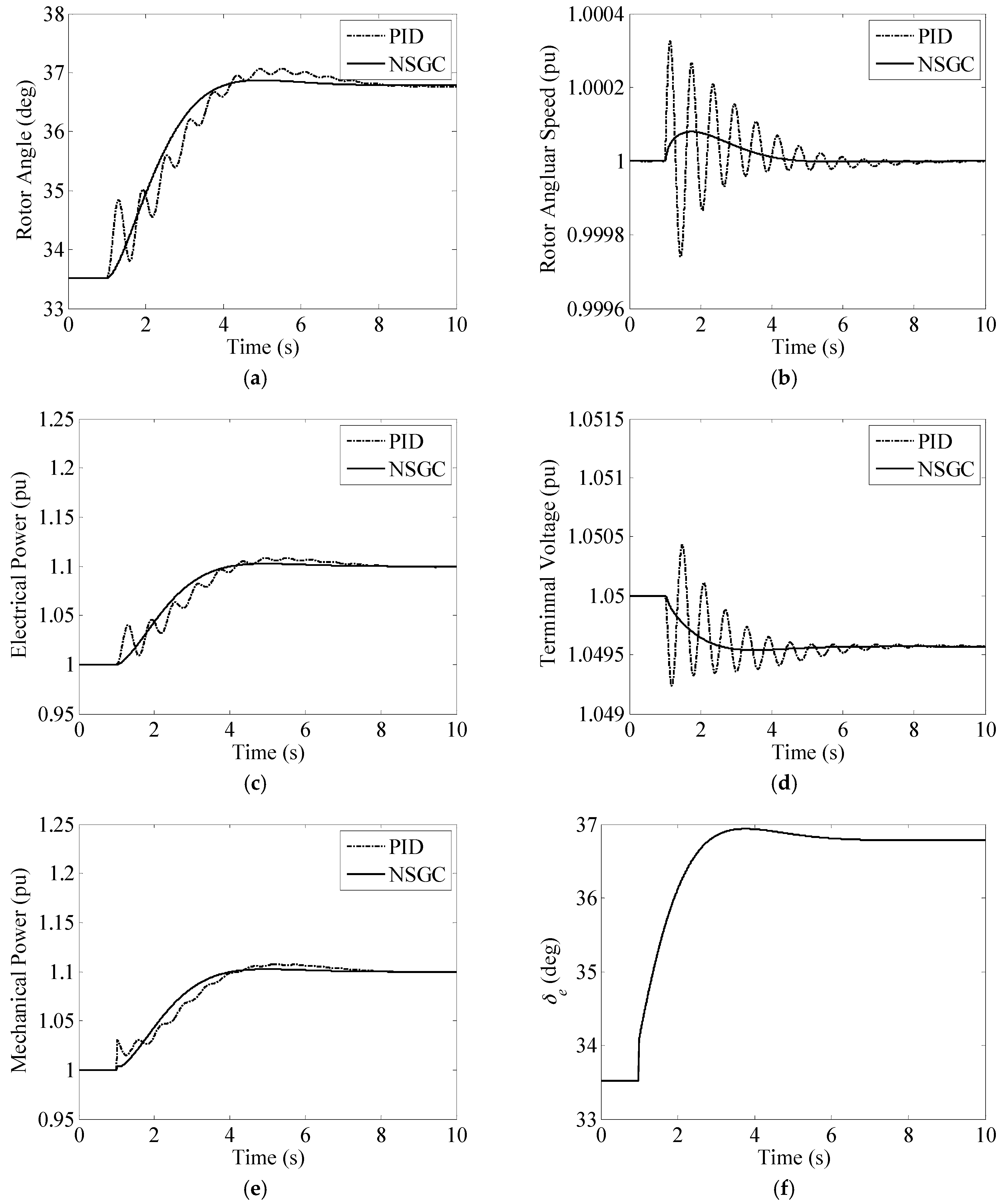
Figure 7.
Macro-variable ψ response to a load disturbance.

Figure 8.
New England power system.
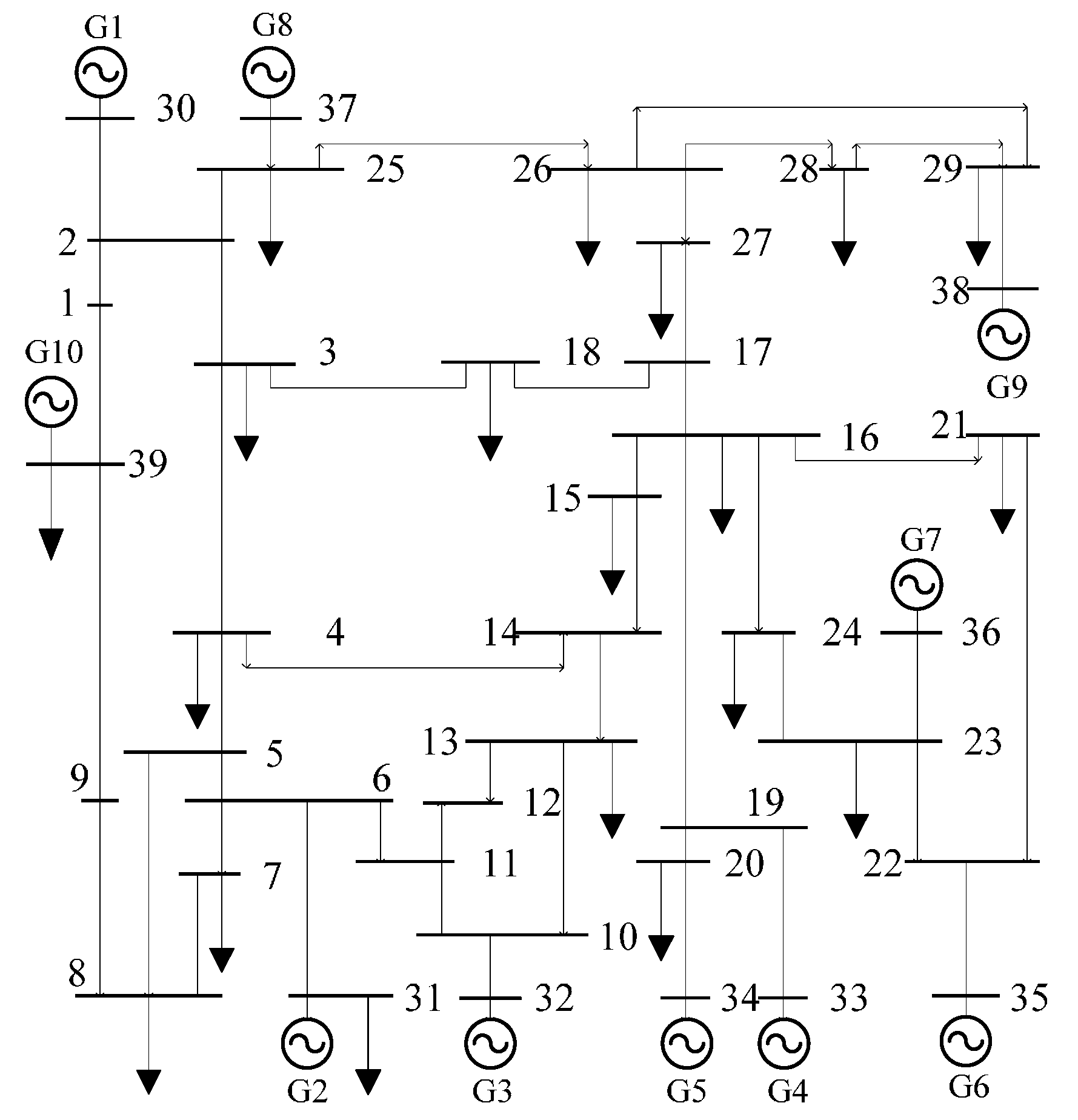
Figure 9.
Electrical power response against a short circuit under operating condition 1. (a) Conventional PID governor controller; (b) Nonlinear synergetic governor controller.
Figure 9.
Electrical power response against a short circuit under operating condition 1. (a) Conventional PID governor controller; (b) Nonlinear synergetic governor controller.
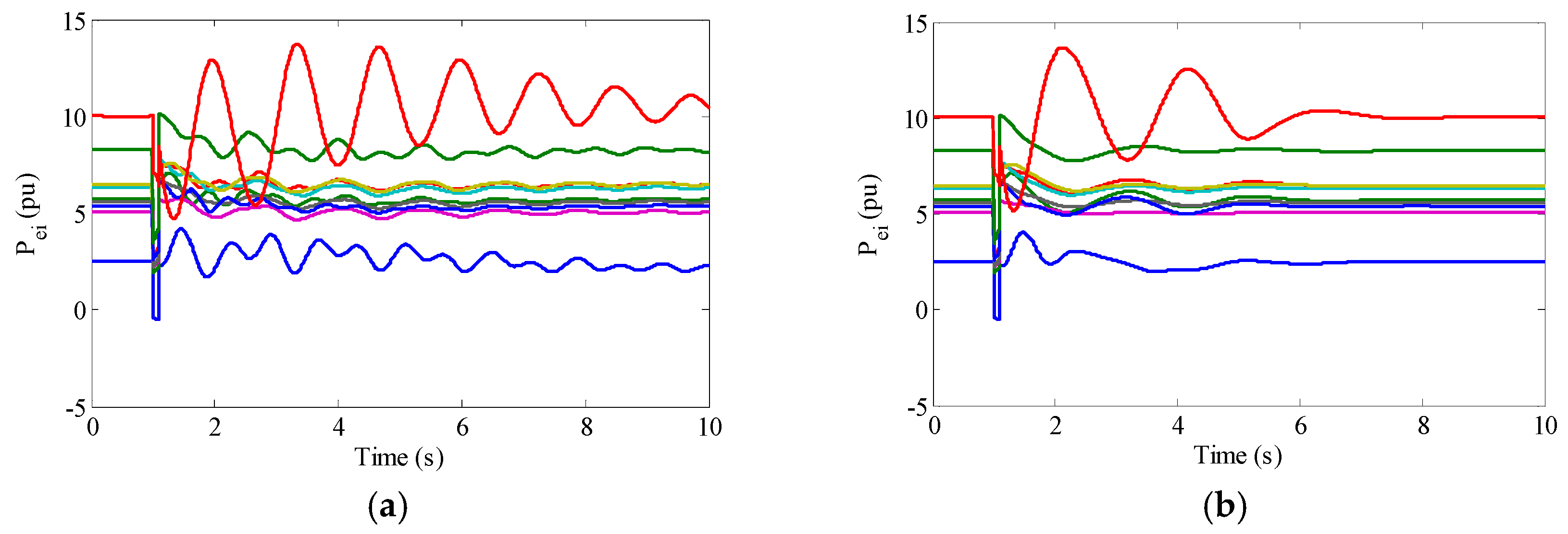
Figure 10.
Rotor angle δi-δ10 response against a short circuit under operating condition 1. (a) Conventional PID governor controller; (b) Nonlinear synergetic governor controller.
Figure 10.
Rotor angle δi-δ10 response against a short circuit under operating condition 1. (a) Conventional PID governor controller; (b) Nonlinear synergetic governor controller.
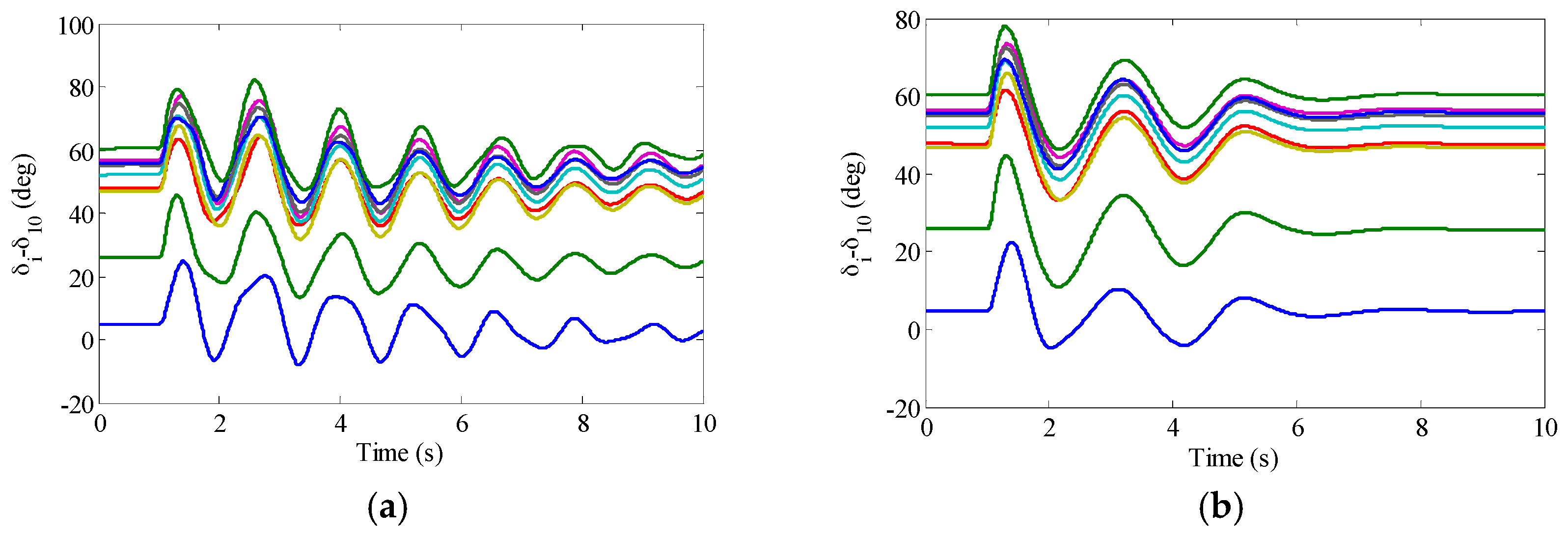
Figure 11.
Rotor speed ωi-ω10 response against a short circuit under operating condition 1. (a) Conventional PID governor controller; (b) Nonlinear synergetic governor controller.
Figure 11.
Rotor speed ωi-ω10 response against a short circuit under operating condition 1. (a) Conventional PID governor controller; (b) Nonlinear synergetic governor controller.
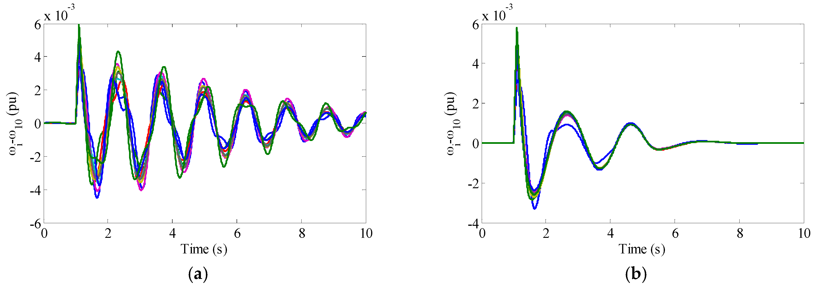
Figure 12.
Electrical power response against a short circuit under operating condition 2. (a) Conventional PID governor controller; (b) Nonlinear synergetic governor controller.
Figure 12.
Electrical power response against a short circuit under operating condition 2. (a) Conventional PID governor controller; (b) Nonlinear synergetic governor controller.

Figure 13.
Rotor angle δi-δ10 response against a short circuit under operating condition 2. (a) Conventional PID governor controller; (b) Nonlinear synergetic governor controller.
Figure 13.
Rotor angle δi-δ10 response against a short circuit under operating condition 2. (a) Conventional PID governor controller; (b) Nonlinear synergetic governor controller.
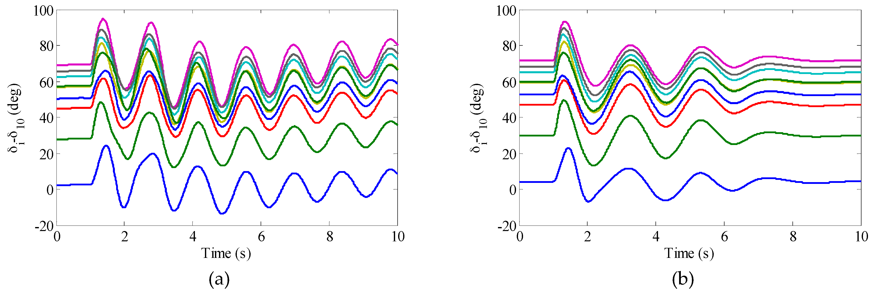
Figure 14.
Rotor speed ωi-ω10 response against a short circuit under operating condition 2. (a) Conventional PID governor controller; (b) Nonlinear synergetic governor controller.
Figure 14.
Rotor speed ωi-ω10 response against a short circuit under operating condition 2. (a) Conventional PID governor controller; (b) Nonlinear synergetic governor controller.


Table 1.
Active power outputs of generators under different operating conditions.
| Generator No. | Operating Condition 1 (pu) | Operating Condition 2 (pu) |
|---|---|---|
| 1 | 2.5 | 1.7 |
| 2 | 5.73 | 5.798 |
| 3 | 6.5 | 5.7 |
| 4 | 6.32 | 7.32 |
| 5 | 5.08 | 6.08 |
| 6 | 6.5 | 7.5 |
| 7 | 5.6 | 6.6 |
| 8 | 5.4 | 4.6 |
| 9 | 8.3 | 7.5 |
| 10 | 10 | 8.9 |
© 2017 by the authors. Licensee MDPI, Basel, Switzerland. This article is an open access article distributed under the terms and conditions of the Creative Commons Attribution (CC BY) license (http://creativecommons.org/licenses/by/4.0/).
Share and Cite
MDPI and ACS Style
Ju, X.; Zhao, P.; Sun, H.; Yao, W.; Wen, J. Nonlinear Synergetic Governor Controllers for Steam Turbine Generators to Enhance Power System Stability. Energies 2017, 10, 1092. https://doi.org/10.3390/en10081092
AMA Style
Ju X, Zhao P, Sun H, Yao W, Wen J. Nonlinear Synergetic Governor Controllers for Steam Turbine Generators to Enhance Power System Stability. Energies. 2017; 10(8):1092. https://doi.org/10.3390/en10081092
Chicago/Turabian StyleJu, Xingbao, Ping Zhao, Haishun Sun, Wei Yao, and Jinyu Wen. 2017. "Nonlinear Synergetic Governor Controllers for Steam Turbine Generators to Enhance Power System Stability" Energies 10, no. 8: 1092. https://doi.org/10.3390/en10081092
Note that from the first issue of 2016, this journal uses article numbers instead of page numbers. See further details here.