Article

Evaporation and Ignition Characteristics of Water Emulsified Diesel under Conventional and Low Temperature Combustion Conditions

1
State Key Laboratory of Coal Combustion, School of Energy and Power Engineering, Huazhong University of Science and Technology, Wuhan 430074, China
2
School of Civil and Environmental Engineering, University of Technology Sydney, Sydney, NSW 2007, Australia
3
Department of Mechanical Engineering, University of California at Berkeley, Berkeley, CA 94720, USA
*
Authors to whom correspondence should be addressed.
Energies 2017, 10(8), 1109; https://doi.org/10.3390/en10081109
Submission received: 14 April 2017 / Revised: 29 June 2017 / Accepted: 11 July 2017 / Published: 31 July 2017
(This article belongs to the Special Issue Internal Combustion Engines 2017)

Abstract

:
The combination of emulsified diesel and low temperature combustion (LTC) technology has great potential in reducing engine emissions. A visualization study on the spray and combustion characteristics of water emulsified diesel was conducted experimentally in a constant volume chamber under conventional and LTC conditions. The effects of ambient temperature on the evaporation, ignition and combustion characteristics of water emulsified diesel were studied under cold, evaporating and combustion conditions. Experimental results showed that the ambient temperature had little effect on the spray structures, in terms of the liquid core length, the spray shape and the spray area. However, higher ambient temperature slightly reduced the Sauter Mean Diameter (SMD) of the spray droplets. The auto-ignition delay time increased significantly with the decrease of the ambient temperature. The ignition process always occurred at the entrainment region near the front periphery of the liquid core. This entrainment region was evolved from the early injected fuel droplets which were heated and mixed by the continuous entrainment until the local temperature and equivalence ratio reached the ignition condition. The maximum value of integrated natural flame luminosity (INFL) reduced by 60% when the ambient temperature dropped from 1000 to 800 K, indicating a significant decrease of the soot emissions could be achieved by LTC combustion mode than the conventional diesel engines.

1. Introduction

As a promising alternative fuel and combustion mode, water emulsified diesel fuel has attracted much attention in engine research [1,2]. The in-cylinder temperature of diesel engines fuelled with water emulsified diesel could be significantly decreased due to the large latent heat of vaporization [3] and specific heat [4] of water, leading to a simultaneous reduction in NOx and soot emissions. Engine experiments showed that NOx and soot emissions and fuel consumption could be greatly reduced by blending diesel with appropriate ratio of water [5,6]. The optimal fuel economy and emission performance could be obtained at 10–30% water blending ratio [7,8]. At present, combustion with diesel and water could be achieved by three approaches [9], including intake port water injection (WI), direct in-cylinder WI and water emulsified diesel [10]. The first two approaches achieve the diesel-water combustion through the in-cylinder mixing process, while water emulsified diesel achieves it by blending water and diesel before the fuel injection.
As water and diesel exhibit different molecular polarities, pure water is immiscible with diesel fuel. Therefore, surfactants are needed to obtain a stable blend of water and diesel, which is called water-diesel emulsion. The Hydrophilic Lipophilic Balance (HLB) value of a surfactant is the guiding index of choosing an emulsifying solution. A higher HLB value of a surfactant indicates a higher molecular polarity so that the surfactant is easier to dissolve in water, while a lower HLB value means the surfactant is easier to dissolve in diesel. The best HLB value of a surfactant for producing stable emulsified fuel is thought to be 5.0 [11]. In the present study, Span-80 and Op-10 were used to form a new surfactant whose HLB value was 5.07.
Compared with intake port and direct in-cylinder WI, water-emulsified diesel can be directly used in the conventional diesel engines without major modifications. Iwai et al. [12] experimentally investigated the emission performance of pure diesel, intake port WI, and emulsified diesels mixed with 15% and 30% of water. The results showed that NOx and soot emissions of water emulsified diesels were much lower than that of pure diesel due to the micro-explosion of water emulsified diesels. The micro-explosion might occur in multi-component fuel spray and enhance the breakup of fuel spray [13,14], especially in water emulsified diesel and alcohol-diesels. However, very little direct evidence of micro-explosions has been reported in diesel fuel sprays from high pressure common rail systems where there is an extreme degree of cavitation in the injector nozzle. Compared with intake port WI, emulsified diesel with the same proportion of water also had better fuel economy and emission performance. Adopting numerical and experimental study, Samec et al. [15] found a significant emission reduction with no increase in specific fuel consumption by using water/oil emulsified fuel. Chen [16] reported that the water emulsified diesel could exhaust nearly 35% less of soot emission than that of pure diesel fuel.
Combustion temperature is a key factor in the physical and chemical processes of spray combustion. According to the equivalence ratio-temperature (φ-T) map [17], the formation of soot and NOx emissions could be effectively reduced by controlling the distribution of temperature (T) and equivalence ratio (φ), especially under the lower ambient temperature conditions. Lower ambient temperature can lead to lower combustion temperature, which has great mitigation on soot and NOx emissions. The influence of ambient conditions on the spray and combustion processes, including spray, evaporation, breakup, ignition delay, soot oxidation and NOx generation, had been widely studied [18,19,20,21]. As a result, low temperature combustion (LTC), which focuses primarily on reducing in-cylinder combustion temperature, demonstrates great potential in realizing efficient and clean combustion in internal combustion engines. By diluting the in-cylinder combustible mixture, either by excess charge gas or moderate to high level of exhaust gas recirculation (EGR), the combustion temperature can be reduced. Researchers have also proposed many new strategies to achieve LTC, most of which could be generally categorized into two groups, namely the homogeneous charge compression ignition (HCCI) and premixed charge compression ignition (PCCI) [22].
As reviewed above, both water-emulsified diesel and LTC technology have great potential in reducing the emissions of diesel engines. The present study is aimed to investigate the spray and ignition characteristics of water emulsified diesel under various ambient temperature conditions, including cold, evaporating and combustion conditions. The effects of ambient temperature on the spray structure, distribution of equivalence ratio, ignition and flame structure are analyzed. The reported work provides experimental data on the spray, ignition and combustion characteristics of water-emulsified diesel fuel under the conventional and LTC combustion conditions, which will be of great importance for understanding the combustion process inside the combustion chamber, as well as numerical simulation.

2. Experimental Apparatus and Procedures

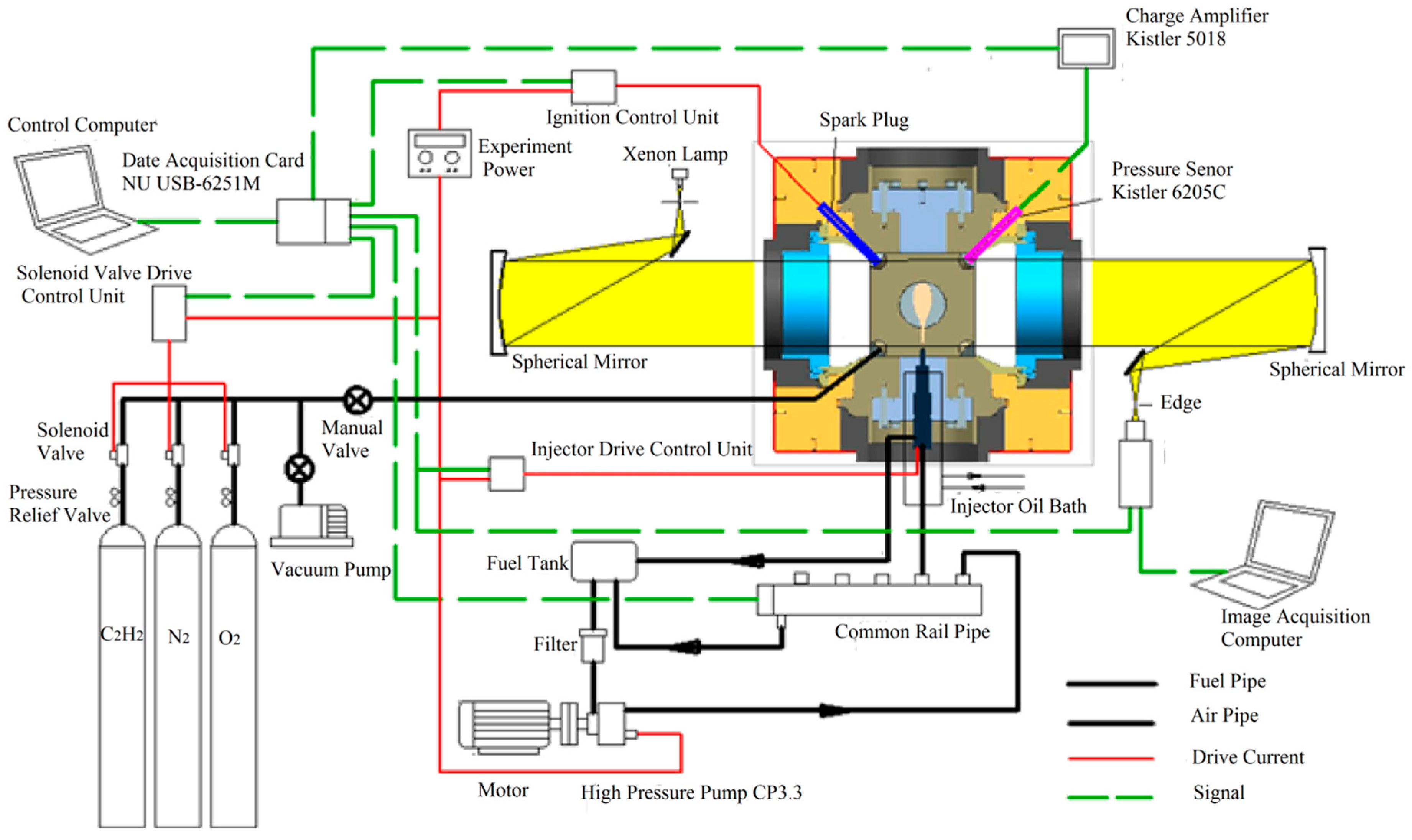
2.1. Constant Volume Chamber Optical System

Figure 1 shows the schematic of the constant volume chamber optical system used in this paper. As shown in Figure 1, the system includes the constant volume chamber, gas supply, ignition, fuel injection, pressure acquisition and high speed imaging systems. The chamber has a shape of a cube with edge length of 136 mm. The diameter of the quartz window is 130 mm. The imaging system consists of a high-speed CCD camera, Schlieren optical components and ND8 neutral density filter. The start of the image recording was synchronized with the injection signal. More details about the constant volume chamber system can be found in references [23,24].
In the Schlieren imaging technique, the collimated light is focused with a lens. A knife-edge is placed at the focal point to block half of the light. For flows with uniform density, this will simply halve the brightness of the images. However, for uneven flows, the distorted beam focuses imperfectly and the captured images will show a set of bright and dark patches corresponding to positive and negative fluid density gradients in the uneven flows. In the spray experiments, the beam generated by a single collimated source passes through the spray zone in the constant volume chamber. Variations of density in the spray zone distort the collimated light beam, which are captured by the high speed Schlieren images.
In the present study, pre-burning of acetylene was used to generate the high ambient temperature and pressure conditions, representing the real in-cylinder engine conditions. The mixture of acetylene, oxygen and nitrogen with designed percentages was charged into the chamber and ignited by a spark plug to generate a high temperature and pressure condition. Then the hot burnt mixture cooled down gradually and the diesel fuel was injected when a target temperature was reached. Different ambient density, oxygen concentration and temperature conditions could be achieved by adjusting the percentages of acetylene, nitrogen and oxygen charged. More details about the pre-burning heating method can be found in references [25,26].
In this paper, a high speed CCD camera (Motion Pro Y4-S1, Integrated Design Tools, Inc. (IDT), Pasadena, CA, USA) was adopted to record the spray and combustion processes, including the spatial and temporal evolution in the cold, evaporating and combustion conditions. The imaging speed was 20,000 fps and the resolution was 640 × 280 pixels. Generally, there are three definitions of ignition delay, namely the species delay, the flame light delay and the pressure rising delay. Species ignition delay is defined as the duration between the start of injection and the initial occurrence of high-temperature OH chemiluminescence radicals. Flame light ignition delay is defined as the duration from the start of injection to the appearance of soot incandesce radicals. Pressure rising delay is defined as the duration from the start of injection to when combustion pressure experiences a rapid rise. In the present study, the pressure rise was not obvious because the amount of fuel injected was relatively small comparing with the large volume of the combustion chamber. Therefore, the pressure rising delay was not analyzed. Pickett [27] and Nakamura [28] showed that the cold flame, high temperature chemiluminescence and soot incandesce occurred in succession during the diesel combustion process. Chemiluminescence can hardly be captured by the CCD camera, but soot incandesce [29,30,31] can be recorded to analyze the ignition and flame characteristics, such as ignition delay, combustion duration, flame luminosity, etc. Therefore, only the flame light ignition delay was analyzed.

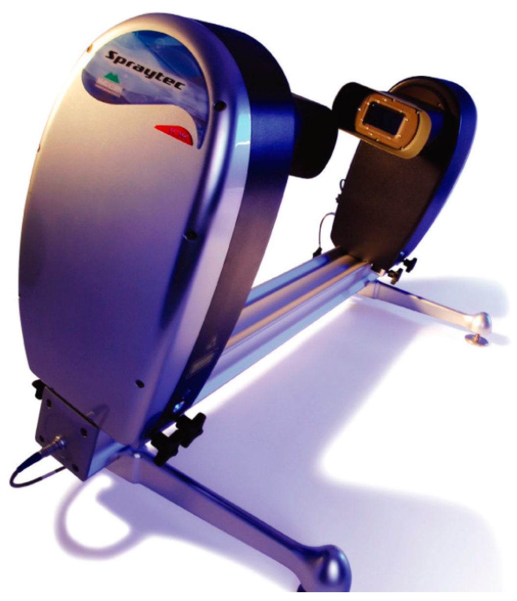
2.2. Malvern Laser Particle Size Analyzer

To measure the Sauter Mean Diameter (SMD) in the droplet breakup process, a Spraytec laser particle size analyzer from Malvern Instruments Ltd (Malvern, Worcestershire, UK) was employed. According to the Mie and the Fraunhofer approximation models, particle size can be measured by laser diffraction theory. Specifically, when a bunch of parallel laser beams from a laser launcher passes through particles of different size, both the laser intensity and angle in the laser receiver will change due to the laser scattering. Therefore, the distribution and diameter of the spray droplet can be analyzed according to the received laser intensity and angle. The sampling frequency and measuring diameter range of the instrument is 10 KHz and 1 μm–2000 μm respectively, which is sufficient to capture the average droplet diameter in the spray process. During the experiment, the light transmittance is decreased when the spray droplet pass through the optical path. In this paper, the trigger light transmittance was set to be 98% for the particle size analyzer. Detailed parameters and a schematic of the laser particle size analyzer are shown in Table 1 and Figure 2, respectively. To compare the effect of ambient temperature on the spray droplet size under evaporating condition, the measurement distance of the analyzer is set to be 50 mm and 70 mm from the injector. This is mainly because the liquid core length under evaporating condition is approximately 30 mm, and the regions at 50 mm and 70 mm downstream the injector can be considered as fully developed spray regions.

2.3. Preparation of Water-Emulsified Diesel and Image Processing

The tested fuel was the emulsified diesel blended with 20% water by mass (W20). Two surfactants, Span-80 and Op-10, were chosen to form a new surfactant with a HLB value of 5.07 due to the low dosage demands. To obtain 2500 g W20, 110 g (4.4%) Span-80 and 9 g (0.4%) Op-10 were needed. 0# diesel, distilled water and the new surfactant were mixed by a JP300G Ultrasonic emulsifier (Jiapeng electronics co, Ltd, Wuhan, China) for half an hour to prepare the emulsion. The prepared W20 could be kept over 15 days without layer formation, which meet the requirements of tested fuel for the investigation in this study. The density of W20 is 851.7 kg/m3 and the viscosity is 5.66 cps.
All the digital images obtained in the study were processed using a MATLAB 2014a program (The MathWorks, Inc. Natick, MA, USA). The program identified the boundaries of spray and flame, and then calculated the macroscopic parameters, including the spray tip penetration, spray area, liquid core length and integrated flame luminosity (INFL). INFL is defined as the sum of the flame luminosity values of all pixels in the combustion area [25]. The detailed definitions of macroscopic parameters and description of image processing program could be found in references. [32,33].

2.4. Experimental Conditions

Table 2 shows the experimental conditions investigated in the present study. A Bosch single hole research injector with a nozzle diameter of 0.234 mm was used. The tested fuel was the emulsified diesel blended with 20% water by mass (W20). The fuel temperature was kept constant at 293 K. The injection pressure was 150 MPa, the injection duration was 2.5 ms and the ambient density was 15 kg/m3. For the cold condition, the ambient oxygen concentration was 0% and the ambient temperature was 383 K. For the evaporating condition, the oxygen concentration was 0% (to prevent combustion) and the ambient temperature varied from 800 K to 1100 K with an interval of 100 K. For the combustion condition, the oxygen concentration was 21% and the ambient temperature varied from 800 K to 1100 K as well.
To ensure the experimental accuracy, each experimental condition was repeated five times, and the results reported in the following sections are the averaged values of the five repeated tests. The repeatability of the sprays and combustion has been discussed in details in previous work by the current authors [25].

3. Results and Discussion

The experimental results will be presented and discussed as follows. Section 3.1 discusses the effects of ambient temperature on the spray evaporation characteristics. The oxygen concentration is 0% to prevent the combustion in the evaporating condition. Section 3.2 and Section 3.3 report the effects of ambient temperature on the ignition and flame and luminosity characteristics, respectively. The oxygen concentration is 21% to enable the combustion process in the combustion condition. The cold spray images in 383 K ambient temperature condition are used as references in Section 3.1 and Section 3.2. The investigated ambient temperature varies from 800 K to 1100 K with an interval of 100 K, which covers the in-cylinder conditions of both conventional and LTC diesel engines.

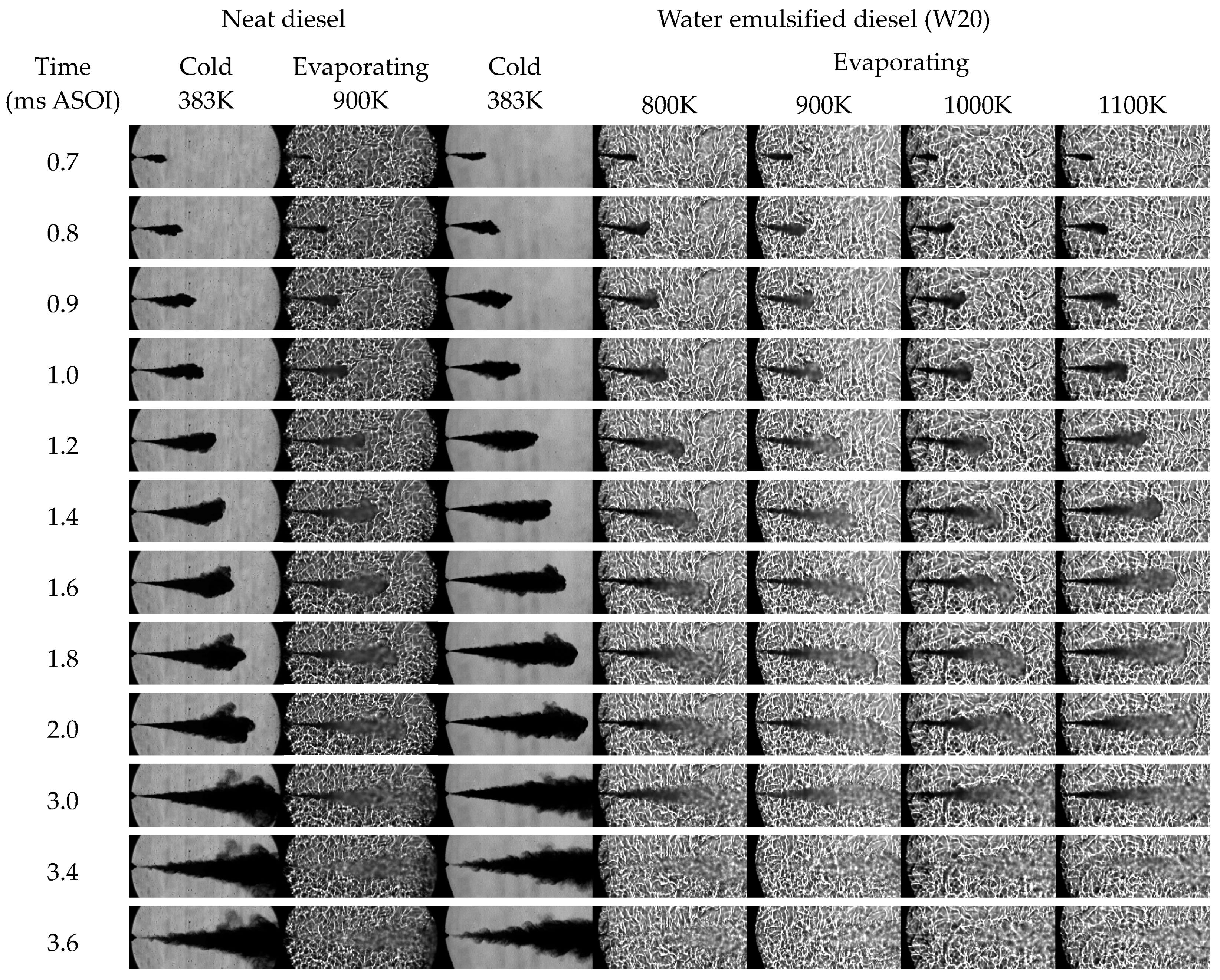
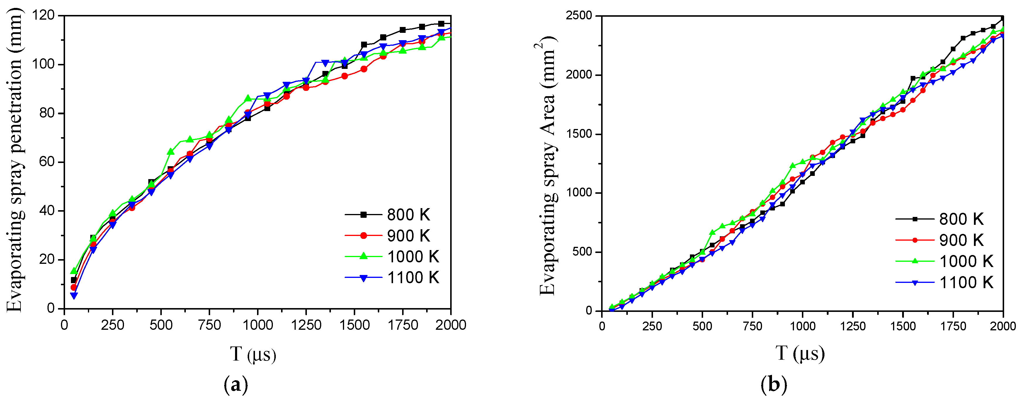
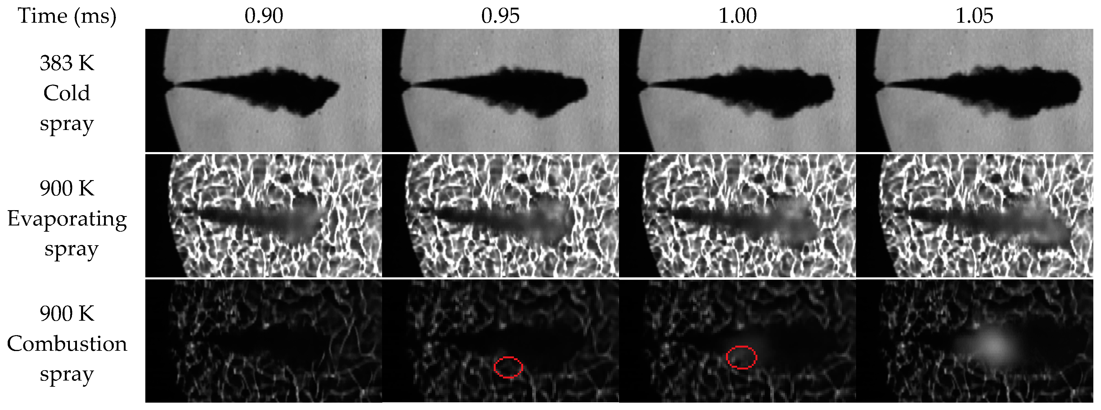
3.1. Effects of Ambient Temperature on the Spray Evaporation Characteristics

Figure 3 shows the spray structures in cold and evaporating conditions of neat diesel (left) and W20 (right). As shown in Figure 3, under cold condition (383 K), the spray penetration of W20 is longer than neat diesel because of the higher density and viscosity of W20. Higher viscosity gives the fuel more ability to resist deformation or split by the relative movement between the air and fuel, leading to stronger spray axial penetration ability. However, higher viscosity also results in smaller spray volume of W20. At 1.6 ms, the spray volume of W20 is 21,926 mm3 which is 20.92% smaller than that of neat diesel (27,725 mm3). With the increase of ambient temperature from 383 K to 900 K, the spray volumes of W20 and neat diesel at 1.6 ms grow by 59.4% and 20.7% respectively. The difference of growth rate implies that the existence of water can promote the spray breakup and mixing processes, which will improve the combustion and soot emission performance.
Regarding the effect of ambient temperature on W20 spray characteristics, as shown in Figure 3, there are two distinct regions in the evaporating spray. One is the dark liquid region and the other is the brighter shaded region. The dark region was mainly consisted of liquid fuel droplets while the brighter region contained mainly fuel vapor [34]. Compared with the cold spray, the evaporating spray droplets at the periphery of the liquid core region gasify quickly due to the heating by the entrained air during the early period (0 ms–0.9 ms). Therefore, there is no vapor region during this period, making the evaporating spray area significantly smaller than that of the cold spray because the high-speed camera cannot capture the gasified fuel in the images. At 1.0 ms after start of injection (ASOI), a brighter vapor zone like aerosol in the spray images starts to appear. It means that, as more fuel is injected, the vapor fuel cannot be completely gasified by the hot air entrained and the liquid fuel droplets mix with the ambient gas to form the vapour-air mixture area. The length of liquid core (dark liquid region) becomes constant after 1.2 ms ASOI (which will be discussed further in Figure 4), indicating that the quasi-steady spray status is established. The injection stops at 2.5 ms ASOI and the fuel in the vapor and liquid core regions continues to evaporate and gasify gradually by the heating of the air entrainment. Finally, all the fuel is nearly completely gasified at 3.4 ms ASOI.
The cold spray images in Figure 3 show many protrusions and burrs in the spray boundary, which are caused by the air entrainment. However, the boundary of the evaporating spray is relatively smooth. This is mainly because the protrusions and burrs are gasified by the hot air entrained in the evaporating condition. Basically, there is no apparent evaporation shaded region near the nozzle exit in the evaporating condition. All the fuel vapors are mainly around the front periphery of the liquid core. The liquid core near the nozzle exit in evaporating condition is much thinner than that of the cold spray. This implies that many fuel droplets around the near-nozzle-exit liquid core zone are gasified completely by the heating of hot air entrained. Those gasified fuel droplets will penetrate to the spray downstream by inertia and the local temperature in those gasified fuel zones will increase with the continuous air entrainment and heating.
Figure 4 shows the spray tip penetration (a), spray area (b) and liquid core length (c) in the evaporating conditions. As shown in Figure 4c, the liquid core length remains almost constant in the ambient temperature range from 800 K–1100 K. Figure 4a,b also show that the spray tip penetration and the spray area are similar to each other in the investigated temperature range. Moreover, the fuel liquid core is completely gasified approximately at the same time of 3.4 ms ASOI. All these demonstrate that the ambient temperature has little effect on the spray structure in the evaporating condition. Instead, the spray structure is mainly determined by the injection parameters, such as the nozzle diameter, ambient pressure, injection pressure and duration. The ambient temperature determines the temperature of the air entrained into the spray, which affects the fuel-air mixture temperature in the entrainment zone and the droplet breakup process in the micro-perspective. However, the ambient temperature cannot change the entrainment and mixing processes in the macro-perspective.
Figure 5 demonstrates the particle volume distribution at 50 mm downstream the injector under 800 K evaporating condition. As shown in Figure 5, the blue bars represent the absolute volume percentage of each size range and the red curve represents the cumulative volume percentage. The droplets’ SMD is 21.54 μm in 800 K.
Figure 6 shows the effects of ambient temperature on the spray droplet SMD. With the increase of ambient temperature, the SMD is gradually reduced. Particularly, when the ambient temperature increases from 383 K (cold spray) to 800 K (evaporating spray), the SMD decreases by 23.29% at 50 mm position and 14.65% at 70 mm position respectively. When the ambient temperature increases from 800 K to 1100 K, the decreasing rate of SMD is 12.55% and 11.68% at 50 mm and 70 mm position respectively. With the increase of the measurement distance, the SMD is reduced gradually as well.

3.2. Effects of Ambient Temperature on the Ignition Characteristics

The ignition process is mainly determined by the local equivalence ratio and temperature. The equivalence ratio reduces from the liquid core to the spray tip in the spray axial direction. It also reduces from the center axis to the outer periphery of the spray in the radial direction. To investigate the ignition process, a group of ignition experiments have been conducted. In these experiments, the ND8 neutral density filters were removed from the CCD camera to record the spray and combustion behaviors simultaneously. Figure 7 shows the ignition process in the ambient temperature of 900 K. As shown in Figure 7, the ignition firstly occurs at 0.95 ms ASOI (indicated by red circles and also visible in Figure 8) at a protrusion near the front periphery of the liquid core. The protrusion is an entrainment region. By comparing with the spray images in the cold and evaporating conditions, it can be seen from the ignition images that the ignition position is beyond the vapor zone. The ignition occurs in the gasification zone, which provides suitable equivalence ratio and temperature for ignition.
Figure 8 shows the ignition and combustion processes of neat diesel under 1100 K and emulsified diesel at various ambient temperatures. The combustion images of neat diesel are used for comparison. In this paper, the time when a light flash is observed in the Schlieren image is defined as the time of the start of ignition.
The time interval from the start of injection to the start of ignition is defined as the ignition delay. The ignition delay has important and complicated effects on the combustion rate, heat release, engine thermal efficiency and emissions. As shown in Figure 8, the ignition delay decreases with the increase of the ambient temperature. The ignition starts at 1.1 ms ASOI at 800 K ambient temperature, while it advances to 0.8 ms ASOI at 1100 K. For the various ambient temperatures investigated, all the ignition position located at the protrusions or burrs around the front periphery of the liquid core. As the ambient temperature increases, the distance between ignition position and injector decreases, which means the ignition region has a larger equivalence ratio. This indicates that the rich ignition limit of equivalence ratio increases with the increase of the ambient temperature. Moreover, both the ignition delay and ignition distance of emulsified diesel are longer than that of neat diesel at 1100 K, indicating that the local temperature rise of emulsified diesel spray is slower than that of neat diesel in the conventional diesel engines.

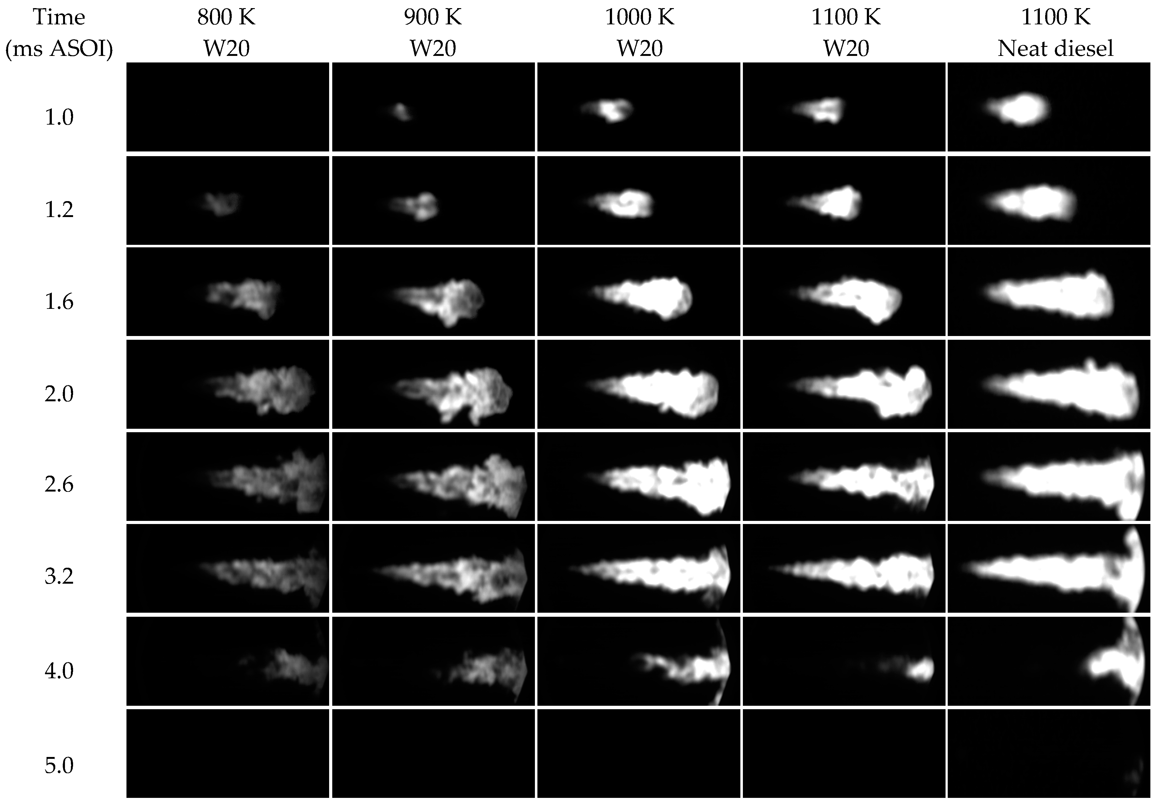
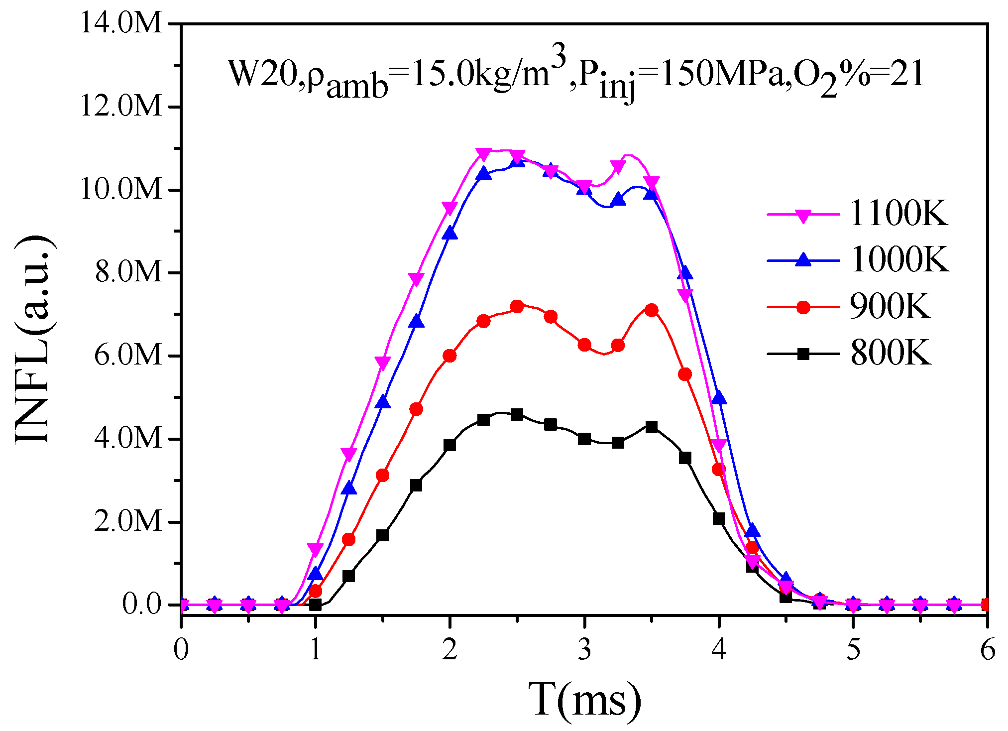
3.3. Effects of Ambient Temperature on Flame and Luminosity

In the present study, the integrated flame luminosity (INFL) is calculated to quantify the effect of ambient temperature on combustion characteristics. INFL [35,36] is defined as the sum of all pixels’ flame luminosity values in the combustion area. Figure 9 shows the flame evolution of neat diesel at 1100 K and emulsified diesel at various ambient temperatures. As shown in Figure 9, the high intensity region of INFL locates at the vapor region near the tip of the liquid core, indicating that the rich vapor zone is the main area of soot formation. As the ambient temperature decreases, the flame luminance decreases and becomes more uniform. This implies that the density of soot generation diminishes and becomes more uniform in the flame area when the ambient temperature decreases. Moreover, the flame luminance of emulsified diesel is obviously darker than that of neat diesel at 1100 K. This indicates that the soot generation intensity of emulsified diesel combustion is much lower compared to neat diesel.
Figure 10 shows the variation of INFL with time at various ambient temperature conditions. The INFL tendencies of emulsified diesel are similar to each other in the investigated ambient temperature range. There are two stages in the spray combustion process. The first stage is the premixed combustion, during which the INFL increases significantly and then decreases slightly. Then the diffusion combustion occurs after the premixed fuel-air mixture is burnt out. In the diffusion combustion, the INFL increases again and a second INFL peak can be observed. As shown in Figure 10, the maximum INFL value increases significantly with the increase of the ambient temperature from 800 K to 900 K and from 900 K to 1000 K. However, INFL only increases slightly from 1000 K to 1100 K. This kind of INFL tendency is resulting from different reaction path at different ambient temperature. When the ambient temperature is 800 K, the reaction of fuel is a kind of lower temperature reaction, which means that the main reaction for diesel fuel is the dehydrogenation and oxygen addition reaction of n-heptane. There is just a little cleavage reaction of n-heptane long chain which will produce the PAHs for soot generation, so the generation rate of soot is lower. When the ambient temperature reaches 900 K, the reaction of fuel is a kind of intermediate temperature reaction, in which there are some cleavage reactions of n-heptane long chain which will produce the PAHS, so the generation rate of soot increased. When the ambient temperature reaches 1000 K, the reaction of fuel is a kind of intermediate temperature reaction, in which the main reaction is the cleavage reactions of n-heptane will produce the many PAHs to form soot. Based on the INFL tendency, it implies that the mass of soot generated decreases significantly when the ambient temperature drops from 1000 K (for traditional diesel engine) to 800 K (for LTC engine) by 60%. From the attenuation of flame brightness at the late stage of combustion, the decay rate of flame brightness rises with the increase of ambient temperature. Therefore, the destruction and oxidation of soot are facilitated under higher ambient temperature conditions. However, the overall effect of ambient temperature on soot emission is negative because more soot is generated at higher temperature. Moreover, the ignition delay decreases gradually with the increase of ambient temperature. The ignition delay of 800 K is much longer than that of 1100 K. The longer the ignition delay is, the more air is entrained into the spray and the smaller the local equivalence ratio is. This means that the fuel is burned with leaner mixture when ambient temperature is lower. Meanwhile, as the ignition delay becomes longer, more fuel is burned in premixed combustion. This means more fuel is burned at lower equivalence ratio as the ambient temperature decreases, and consequently the soot generation decreases.

4. Conclusions

The present study experimentally investigated the spray and combustion characteristics of water emulsified diesel (W20) in a constant volume chamber. The effects of ambient temperature on the evaporation, ignition and combustion characteristics of W20 were analyzed in cold, evaporating and combustion conditions. The major conclusions of the present study can be drawn as follows.
(1)
The liquid core length, shape and area of the spray were similar at various ambient temperatures in the evaporating condition, indicating that the ambient temperature had little effect on the spray structure. The spray structure was mainly determined by the injection parameters, rather than the ambient temperature. However, higher ambient temperature reduced the Sauter Mean Diameter (SMD) of the spray droplets.
(2)
The auto-ignition delay time increased significantly with the decrease of the ambient temperature. The ignition process always occurred at the entrainment region near the front periphery of the liquid core. This entrainment region was evolved from the early injected fuel droplets which were heated and mixed by the continuous entrainment until the local temperature and equivalence ratio reached the ignition condition.
(3)
The maximum value of integrated natural flame luminosity (INFL) reduced by 60% when the ambient temperature dropped from 1000 to 800 K, indicating a significant decrease of the soot emissions could be achieved by Low Temperature Combustion (LTC) compared with the conventional diesel engine combustion mode.

Acknowledgments

This work was supported by State Key Laboratory of Engines, Tianjin University (K2017-08) and the National Natural Science Foundation of China (Grants 51576083). The supports provided by Peng Deng, Sheng Huang and Jie Tang during the experiments are greatly appreciated.

Author Contributions

Zhaowen Wang conceived and designed the experiments; Shang Wu performed the experiments; Zhaowen Wang and Yuhan Huang analyzed the data; All the authors contributed to writing and revising the paper. Authorship is limited to those who have contributed substantially to the work reported.

Conflicts of Interest

The authors declare no conflict of interest. The founding sponsors had no role in the design of the study; in the collection, analyses, or interpretation of data; in the writing of the manuscript, and in the decision to publish the results.

References

  1. Chintala, V.; Subramanian, K.A. Hydrogen energy share improvement along with NOx (oxides of nitrogen) emission reduction in a hydrogen dual-fuel compression ignition engine using water injection. Energy Convers. Manag. 2014, 83, 249–259. [Google Scholar] [CrossRef]
  2. Hountalas, D.T.; Mavropoulos, G.C.; Zannis, T.C.; Mamalis, S.D. Use of water emulsion and intake water injection as NOx reduction techniques for heavy duty diesel engines. SAE Tech. Pap. 2006. [Google Scholar] [CrossRef]
  3. Ithnin, A.M.; Ahmad, M.A.; Bakar, M.A.A.; Rajoo, S.; Yahya, W.J. Combustion performance and emission analysis of diesel engine fuelled with water-in-diesel emulsion fuel made from low-grade diesel fuel. Energy Convers. Manag. 2015, 90, 375–382. [Google Scholar] [CrossRef]
  4. Ogunkoya, D.; Li, S.; Rojas, O.J.; Fang, T. Performance, combustion, and emissions in a diesel engine operated with fuel-in-water emulsions based on lignin. Appl. Energy 2015, 154, 851–861. [Google Scholar] [CrossRef]
  5. Tauzia, X.; Maiboom, A.; Shah, S.R. Experimental study of inlet manifold water injection on combustion and emissions of an automotive direct injection diesel engine. Energy 2010, 35, 3628–3639. [Google Scholar] [CrossRef]
  6. Hountalas, D.T.; Mavropoulos, G.C.; Zannis, T.C. Comparative evaluation of EGR, intake water injection and fuel/water emulsion as NOx reduction techniques for heavy duty diesel engines. SAE Tech. Pap. 2007. [Google Scholar] [CrossRef]
  7. Zhang, W.; Chen, Z.; Shen, Y.; Shu, G.; Chen, G.; Xu, B.; Zhao, W. Influence of water emulsified diesel & oxygen-enriched air on diesel engine NO-smoke emissions and combustion characteristics. Energy 2013, 55, 369–377. [Google Scholar]
  8. Fahd, M.E.A.; Wenming, Y.; Lee, P.S.; Chou, S.K.; Yap, C.R. Experimental investigation of the performance and emission characteristics of direct injection diesel engine by water emulsion diesel under varying engine load condition. Appl. Energy 2013, 102, 1042–1049. [Google Scholar] [CrossRef]
  9. Kegl, B.; Pehan, S. Reduction of diesel engine emissions by water injection. SAE Tech. Pap. 2001. [Google Scholar] [CrossRef]
  10. Alahmer, A.; Yamin, J.; Sakhrieh, A.; Hamdan, M.A. Engine performance using emulsified diesel fuel. Energy Convers. Manag. 2010, 51, 1708–1713. [Google Scholar] [CrossRef]
  11. Huo, M.; Lin, S.; Liu, H.; Lee, C.-F.F. Study on the spray and combustion characteristics of water-emulsified diesel. Fuel 2014, 123, 218–229. [Google Scholar] [CrossRef]
  12. Iwai, M.; Yoshida, K.; Iijima, A.; Shoji, H. Study on performance of diesel engine applied with emulsified diesel fuel. SAE Tech. Pap. 2011. [Google Scholar] [CrossRef]
  13. Watanabe, H.; Suzuki, Y.; Harada, T.; Matsushita, Y.; Aoki, H.; Miura, T. An experimental investigation of the breakup characteristics of secondary atomization of emulsified fuel droplet. Energy 2010, 35, 806–813. [Google Scholar] [CrossRef]
  14. Park, S.; Woo, S.; Kim, H.; Lee, K. The characteristic of spray using diesel water emulsified fuel in a diesel engine. Appl. Energy 2016, 176, 209–220. [Google Scholar] [CrossRef]
  15. Samec, N.; Kegl, B.; Dibble, R.W. Numerical and experimental study of water/oil emulsified fuel combustion in a diesel engine. Fuel 2002, 81, 2035–2044. [Google Scholar] [CrossRef]
  16. Chen, X. Visualization Study on Spray and Combustion Characteristics of Emulsified Diesel Blending with Water by a Constant Volume Chamber; Huazhong University of Science and Technology: Wuhan, China, 2015. [Google Scholar]
  17. Akihama, K.; Takatori, Y.; Inagaki, K.; Sasaki, S.; Dean, A.M. Mechanism of the smokeless rich diesel combustion by reducing temperature. SAE Tech. Pap. 2001. [Google Scholar] [CrossRef]
  18. Kim, K.; Bae, C.; Johansson, B. Spray and combustion visualization of gasoline and diesel under different ambient conditions in a constant volume chamber. SAE Tech. Pap. 2013. [Google Scholar] [CrossRef]
  19. Zhang, J.; Jing, W.; Roberts, W.L.; Fang, T. Soot measurements for diesel and biodiesel spray combustion under high temperature highly diluted ambient conditions. Fuel 2014, 135, 340–351. [Google Scholar] [CrossRef]
  20. Joo, H.I.; Gülder, Ö.L. Experimental study of soot and temperature field structure of laminar co-flow ethylene–air diffusion flames with nitrogen dilution at elevated pressures. Combust. Flame 2011, 158, 416–422. [Google Scholar] [CrossRef]
  21. Pickett, L.M.; Siebers, D.L. Soot in diesel fuel jets: Effects of ambient temperature, ambient density, and injection pressure. Combust. Flame 2004, 138, 114–135. [Google Scholar] [CrossRef]
  22. Musculus, M.P.B.; Miles, P.C.; Pickett, L.M. Conceptual models for partially premixed low-temperature diesel combustion. Prog. Energy Combust. Sci. 2013, 39, 246–283. [Google Scholar] [CrossRef]
  23. Huang, Y.; Huang, S.; Huang, R.; Hong, G. Spray and evaporation characteristics of ethanol and gasoline direct injection in non-evaporating, transition and flash-boiling conditions. Energy Convers. Manag. 2016, 108, 68–77. [Google Scholar] [CrossRef]
  24. Huang, S.; Deng, P.; Huang, R.; Wang, Z.; Ma, Y.; Dai, H. Visualization research on spray atomization, evaporation and combustion processes of ethanol–diesel blend under LTC conditions. Energy Convers. Manag. 2015, 106, 911–920. [Google Scholar] [CrossRef]
  25. Wang, Z.; Chen, X.; Huang, S.; Chen, Y.; Mack, J.H.; Tang, J.; Li, L.; Huang, R. Visualization study for the effects of oxygen concentration on combustion characteristics of water-emulsified diesel. Fuel 2016, 177, 226–234. [Google Scholar] [CrossRef]
  26. Ma, Y.; Huang, S.; Huang, R.; Zhang, Y.; Xu, S. Spray and evaporation characteristics of n-pentanol–diesel blends in a constant volume chamber. Energy Convers. Manag. 2016, 130, 240–251. [Google Scholar] [CrossRef]
  27. Lillo, P.M.; Pickett, L.M.; Persson, H.; Andersson, O.; Kook, S. Diesel spray ignition detection and spatial/temporal correction. SAE Int. J. Engines 2012, 5, 1330–1346. [Google Scholar] [CrossRef]
  28. Nakamura, M.; Nishioka, D.; Hayashi, J.; Akamatsu, F. Soot formation, spray characteristics, and structure of jet spray flames under high pressure. Combust. Flame 2011, 158, 1615–1623. [Google Scholar] [CrossRef]
  29. Wang, X.; Huang, Z.; Kuti, O.A.; Zhang, W.; Nishida, K. An experimental investigation on spray, ignition and combustion characteristics of biodiesels. Proc. Combust. Inst. 2011, 33, 2071–2077. [Google Scholar] [CrossRef]
  30. Chen, R.; Nishida, K. Spray evaporation of ethanol–gasoline-like blend and combustion of ethanol–gasoline blend injected by hole-type nozzle for direct-injection spark ignition engines. Fuel 2014, 134, 263–273. [Google Scholar] [CrossRef]
  31. Britto, R.F.; Martins, C.A. Experimental analysis of a diesel engine operating in Diesel–Ethanol Dual-Fuel mode. Fuel 2014, 134, 140–150. [Google Scholar] [CrossRef]
  32. Wang, Z.; CHEN, X.; Vuilleumier, D.; Huang, S.; Tang, J. Experimental study on spray characteristics of emulsified diesel blending with water in a constant volume chamber. At. Sprays 2016, 26, 513–533. [Google Scholar] [CrossRef]
  33. Ma, Y.J.; Huang, R.H.; Deng, P.; Huang, S. The development and application of an automatic boundary segmentation methodology to evaluate the vaporizing characteristics of diesel spray under engine-like conditions. Meas. Sci. Technol. 2015, 26, 045004. [Google Scholar] [CrossRef]
  34. Pickett, L.M.; Kook, S.; Williams, T.C. Visualization of diesel Spray penetration, cool-flame, ignition, high-temperature combustion, and soot formation using high-speed imaging. SAE Int. J. Engines 2009, 2, 439–459. [Google Scholar] [CrossRef]
  35. Dec, J.E.; Espey, C. Chemiluminescence imaging of autoignition in a DI diesel engine. SAE Tech. Pap. 1998. [Google Scholar] [CrossRef]
  36. Ma, Y.; Huang, S.; Huang, R.; Zhang, Y.; Xu, S. Ignition and combustion characteristics of n-pentanol–diesel blends in a constant volume chamber. Appl. Energy 2017, 185, 519–530. [Google Scholar] [CrossRef]
Figure 1. Schematic of the constant volume chamber optical system.
Energies 10 01109 g001
Figure 2. Schematic of the laser particle size analyzer.
Energies 10 01109 g002
Figure 3. Spray images in cold and evaporating conditions.
Energies 10 01109 g003
Figure 4. Spray characteristics in evaporating conditions: (a) Spray tip penetration; (b) Spray area; (c) Liquid core lengths.
Energies 10 01109 g004aEnergies 10 01109 g004b
Figure 5. Particle volume distribution at 50 mm position in 800 K.
Energies 10 01109 g005
Figure 6. Effects of ambient temperature on SMD.
Energies 10 01109 g006
Figure 7. Demonstration of the ignition process between cold, 900 K evaporating and 900 K combustion conditions.
Energies 10 01109 g007
Figure 8. Ignition and combustion processes of neat diesel under 1100 K and W20 under various ambient temperatures.
Energies 10 01109 g008
Figure 9. Flame evolution of neat diesel under 1100 K and W20 under various ambient temperatures.
Energies 10 01109 g009
Figure 10. Variation of INFL with time.
Energies 10 01109 g010
Table 1. Specifications of the laser particle size analyzer.
Measuring PrincipleLaser Diffraction
Optical modelMie and the Fraunhofer approximation models
Particle size range1 to 2000 μm
Light source5 mw, He-Ne, 633 nm
Optical lens300 mm
Sampling frequency10 KHz
Trigger modeAutomatic triggering based on light transmittance
Table 2. Experimental conditions.
ParametersConditions
Test fuelW20
Fuel temperature293 K
InjectorBosch CRIN 2, single hole, SAC
Nozzle diameter0.234 mm
Injection duration2.5 ms
Injection pressure150 MPa
Ambient density15.0 kg/m3
Ambient oxygen concentration21% (combustion condition)
0% (cold and evaporating conditions)
Ambient temperature383 K (cold condition)
800 K, 900 K, 1000 K and 1100 K (evaporating and combustion conditions)

