Investigation on a Power Coupling Steering System for Dual-Motor Drive Tracked Vehicles Based on Speed Control


1
National Engineering Laboratory for Electric Vehicles, Beijing Institute of Technology, Beijing 100081, China
2
Co-Innovation Center of Electric Vehicles in Beijing, Beijing Institute of Technology, Beijing 100081, China
*
Author to whom correspondence should be addressed.
Energies 2017, 10(8), 1118; https://doi.org/10.3390/en10081118
Submission received: 24 June 2017
/
Revised: 26 July 2017
/
Accepted: 28 July 2017
/
Published: 1 August 2017
(This article belongs to the Special Issue Methods to Improve Energy Use in Road Vehicles)
Abstract
:Double-motor drive tracked vehicles (2MDTV) are widely used in the tracked vehicle industry due to the development of electric vehicle drive systems. The aim of this paper is to solve the problem of insufficient propulsion motor torque in low-speed, small-radius steering and insufficient power in high-speed large-radius steering. In order to do this a new type of steering system with a coupling device is designed and a closed-loop control strategy based on speed is adopted to improve the lateral stability of the vehicle. The work done entails modeling and simulating the 2MDTV and the proposed control strategy in RecurDyn and Matlab/Simulink. The simulation results show that the 2MDTV with the coupling device outputs more torque and power in both steering cases compared to the 2MDTV without the coupling device, and the steering stability of the vehicle is improved by using the strategy based on speed.
1. Introduction
The addition of a track to a vehicle improves the vehicle’s traction on soft surfaces, therefore tracks are found on a variety of vehicles such as bulldozers, excavators, tanks, tractors and any vehicle whose application would benefit from the increased traction. Such vehicles are widely used in many areas such as the military, agriculture, construction, mining, and disaster rescue [1]. Although there are many studies on traditional tracked vehicles [2,3,4], there is still a need for more investigations on electric tracked vehicles. In recent years, with the development of high-power electronic devices, computer control technology and drive motors with high power and high efficiency, electrical drive control technology has made a breakthrough [5].
An electric drive system can be used not only to meet the required dynamic performance of the vehicle, but also to provide energy for electromagnetic weapons [6]. The hybrid electric powertrain with energy management strategies can provide more flexibility to meet driver demand and improve the fuel economy [7]. Moreover, compared to traditional vehicles, electric tracked vehicles’ CO and NOx emissions are reduced [8], making electric drive technology an important research direction in regard to tracked vehicle propulsion.
The dual-motor independent drive configuration is the most widely used configuration in electric tracked vehicles [9,10,11]. This electric propulsion system which is composed of two AC induction motors, final drives and running gears is characterized by complicated multi-variables and nonlinearity [12]. The need for high speed, heavy load and automation has imposed higher and higher requirements on the stability, reliability, controllability and maneuverability of the vehicles [13].
Skid steering is predominantly used with tracked vehicles, that is to say vehicles are steered by forcing the traction elements on opposite sides of the vehicle to run at different speeds [14]. There have been many other investigations into the steady-state handling characteristics and steering mechanisms [15]. The steady-state handling theory is based on analyzing the sliding motion of the track over the ground however few studies focus on the electric stability control of dynamic steering. The torque of outer motor required for the small radius steering will be quite large during a dynamic steering situation. At higher vehicle speeds the torque output of propulsion motors is limited by their power rating, so they could not necessarily contribute so much to vehicle steering.
In order to solve the above problems of the dual-motor independent drive tracked vehicle, it is necessary to design a power coupling steering device. An electro-mechanical drive system with a horizontal axis steering structure is proposed to solve the problem of needing to use large electric motors whose power requirements are far beyond those of the pure drive power [16]. However these needs lots of idle gears and this increases the size of the assembly. A mechanical coupling device is used to decrease the traction power of the unilateral drive motor, which allows the regenerated power to flow from the low-speed side to the high-speed side mechanically [17]. This is quite complex due to the application of three planetary gear systems. A planetary gear coupling device is proposed to improve the efficiency of the inner side motor [18]. Though the efficiency of the motor is higher with the two planetary gear system, it requires higher accuracy for the control system. An electromechanical coupling transmission model with an auxiliary motor was proposed to increase the output torque or power of the motor [19], however the working principle and structural design of the coupling system were not described in detail. There are many studies which focus on the lateral dynamic motion of electric vehicles [20,21], some of which cover electric tracked vehicles [15,22], but few studies take dynamic steering into account. The torque or the power required by the vehicle will be much larger during transients.
This paper aimed at solving the following problems by designing a power coupling steering system: (1) shortage of propulsion motor torque at low speeds and small radius steering, and (2) insufficient power at high speed and large radius steering. The lateral stability of the vehicle is improved by employing a closed loop control strategy based on speed. On running the simulation in RecurDyn and Matlab/Simulink, the results show the yaw rate for vehicles with the coupling device increases to the ideal value rapidly and the vehicle achieves better trajectory following.
2. Mathematical Model for Dynamic Steering
In order to steer a tracked vehicle, it is necessary to drive one track faster than the other, causing the vehicle to turn to the slower track. One of the ways this is executed is by using a dual-motor independent drive with two motor controllers to control the torque and speed of the two motors which drive the sprocket. This is called an electronic control differential steering system (ECDS) which can improve vehicle’s stability, handling and flexibility.
The objective of this paper is to solve the problems of insufficient torque during small radius steering and the shortage of power in high-speed large radius steering. First we selected a tracked vehicle which is the object of our mathematical modeling and analysis. The selected vehicle's configuration is shown in Table 1. Secondly, we analyzed the tracked vehicle’s kinematics and dynamics for stationary steering and dynamic steering in order to study the torque and power required by propulsion motor in both steering cases.
To do this we took right steering as an example, FL is the tractive force on the outer track, FR is the tractive force on the inner track, RL is the rolling resistance force on the outer track, RR is the rolling resistance on the inner track, Mμ is the steering resistance moment, vL is the track speed on the outer side, vR is the track speed on the inner side and ω is the yaw rate. Steering maneuvers with different radiuses can be shown in Figure 1. Mμ is defined as follows:
where μ is the coefficient of roll resistance, μmax is the maximum rolling resistance coefficient, R is the steering radius of the vehicle. The rolling resistance of the two tracks which is the same in magnitude but opposite in direction is expressed as follows:
According to vehicle dynamics performance indicators: First, maximum speed should be 72 km/h. Second, maximum climbing degree should be 32° and climbing speed is 20 km/h. Third, acceleration capability: 0 to 32 km/h less than 8 s. The parameters of the motor are determined as shown in Table 2.
In this paper, the dynamic balance corresponding to different steering maneuvers is analyzed to obtain the torque or power required by an unilateral motor. Then we could find out whether it can meet the requirements during different steering radius.
2.1. R ≤ 0.5 B Steering
The equilibrium relationship between the force and moment of the vehicle when turning from resting, as shown in Figure 1a, can be expressed as:
where FL and FR are tractive force but opposite in direction. It's worth mentioning that when R = 0, FL = FR, VL = VR, lateral acceleration is zero, dv/dt = 0, and when R = 0.5 B, VR = 0, RR = 0.
The motor speed on both sides can be expressed as
where rz is the radius of the sprocket, rz = 150 mm.
From Equations (1)–(4), the motor torque and power can be obtained as follows:
T is the tractive torque but opposite in direction. P is the consumed power used to drive the track. Subscript “L” or “R” means the left or right side of the vehicle.
2.2. R > 0.5 B Steering
According to the vehicle dynamic balance, the following formula can be obtained from Figure 1b:
where FL is the tractive force. If we assume the following equation:
We will get the solution R = R0 = 67.54 m. When R > R0, FR is tractive force and is in the same direction with the track. While when R < R0, FR is brake force, generated by motor. The direction between FR and VR is opposite in this situation.
The vehicle in this steering case can be divided into static starting steering and driving steering, the motor torque and power required vary with the steering radius and speed.
From Equations (1)–(7), Table 3 shows the steering power and torque required by dual motors during dynamic steering maneuvers with 0, 0.2 B, 0.5 B steering radii and stationary steering maneuvers with 0, 0.2 B, 0.5 B, 2 B, 5 B, 8 B, 10 B steering radii.
From Table 3 we can see that when 0 ≤ R ≤ 0.5 B, in both dynamic steering and stationary steering, the motor torque required exceeds the motor's peak torque (150 N·m). When R = 5 B, the power required by the outer side motor is larger than the motor's maximum power (40 kW). When R = 8 B or R = 10 B, the power required by both side motors is larger than the motor’s maximum power (40 kW). According to the results we can find that during small-radius steering (0 ≤ R ≤ 0.5 B) the torque required by a single motor in dynamic steering is 1.5 times that during stationary steering. During large-radius steering (R = 10 B) the power required by the motor is 1.5 times the motor's maximum power therefore the motor's torque and power should increase by 50% at least, which results in large size and mass of the motor and other power inverters. As a result, the superiority of ECDS is not highlighted, and although Zhai [1] proposed a single motor and steering motor coupling system, providing larger torque during small-radius steering, and additional power during high speed large-radius steering while the working principle and structural design of the coupled system were not described in detail.
3. Steering System Design
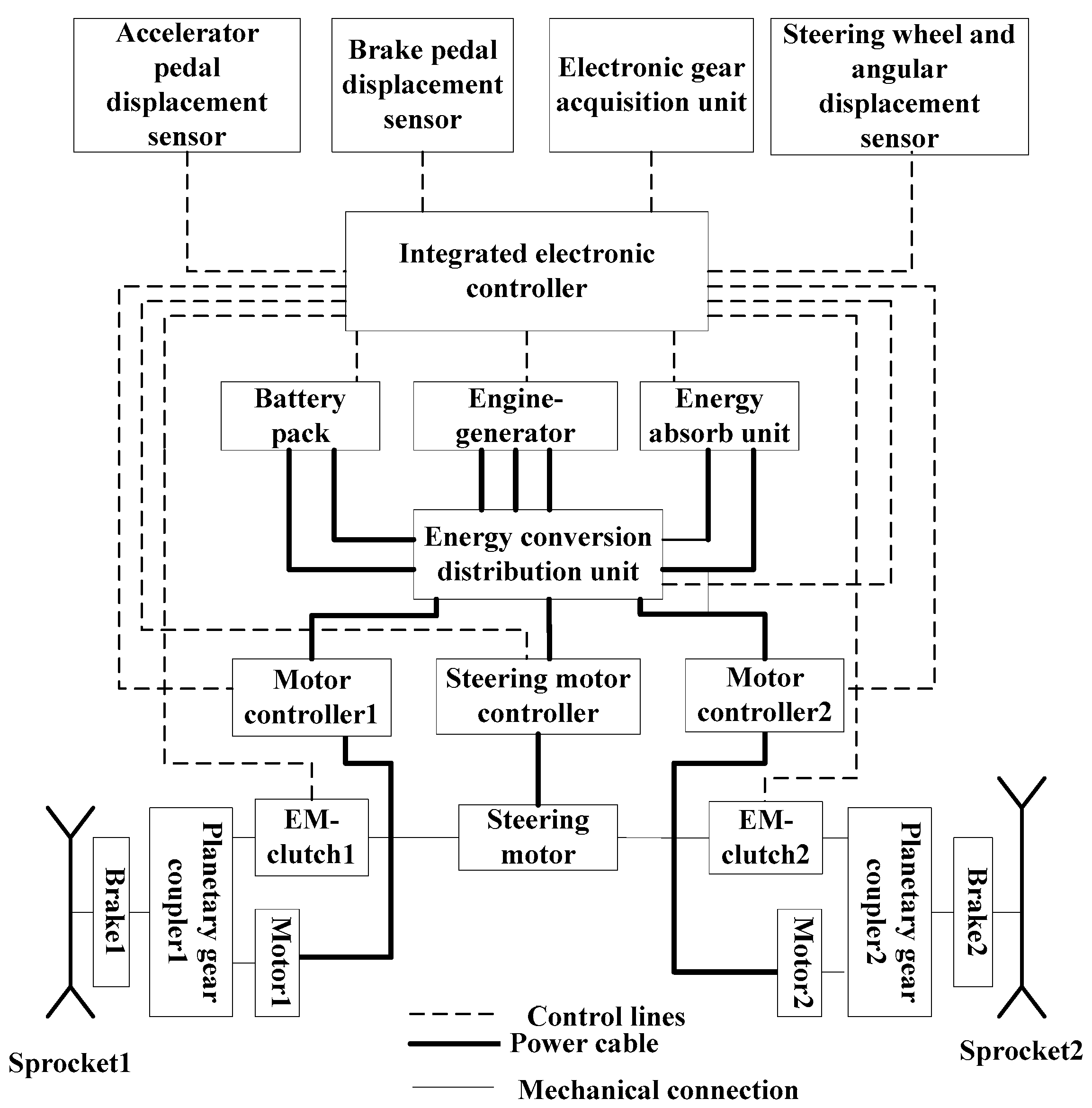
3.1. Steering Coupling Drive System
A steering coupling drive system composed of a new type of center steering motor, two electromagnetic clutches, two planetary gear couplers, and two propulsion motors is designed and shown in Figure 2. The parameters of the steering motor are determined as listed in Table 4. The steering motor can produce large torque at low rotation speed. A reverse mechanism is designed in the steering motor to achieve positive and negative rotation direction. When the torque or power is insufficient, the electromagnetic clutch is engaged and the torque or power of the driving wheel is satisfied by the coupling of the steering motor and the propulsion motor.
3.2. Planetary Gear Coupler Design
A planetary gear coupler is proposed to couple the torque or power of the propulsion motor and the steering motor. The output torque transmitted to the sprocket is increased using the torque coupling mode during low-speed small-radius steering. The output power transmitted to the sprocket is increased using the power coupling mode during high-speed large-radius steering. Therefore the torque or power demand for different radius steering is satisfied and the vehicle steering performance is improved.
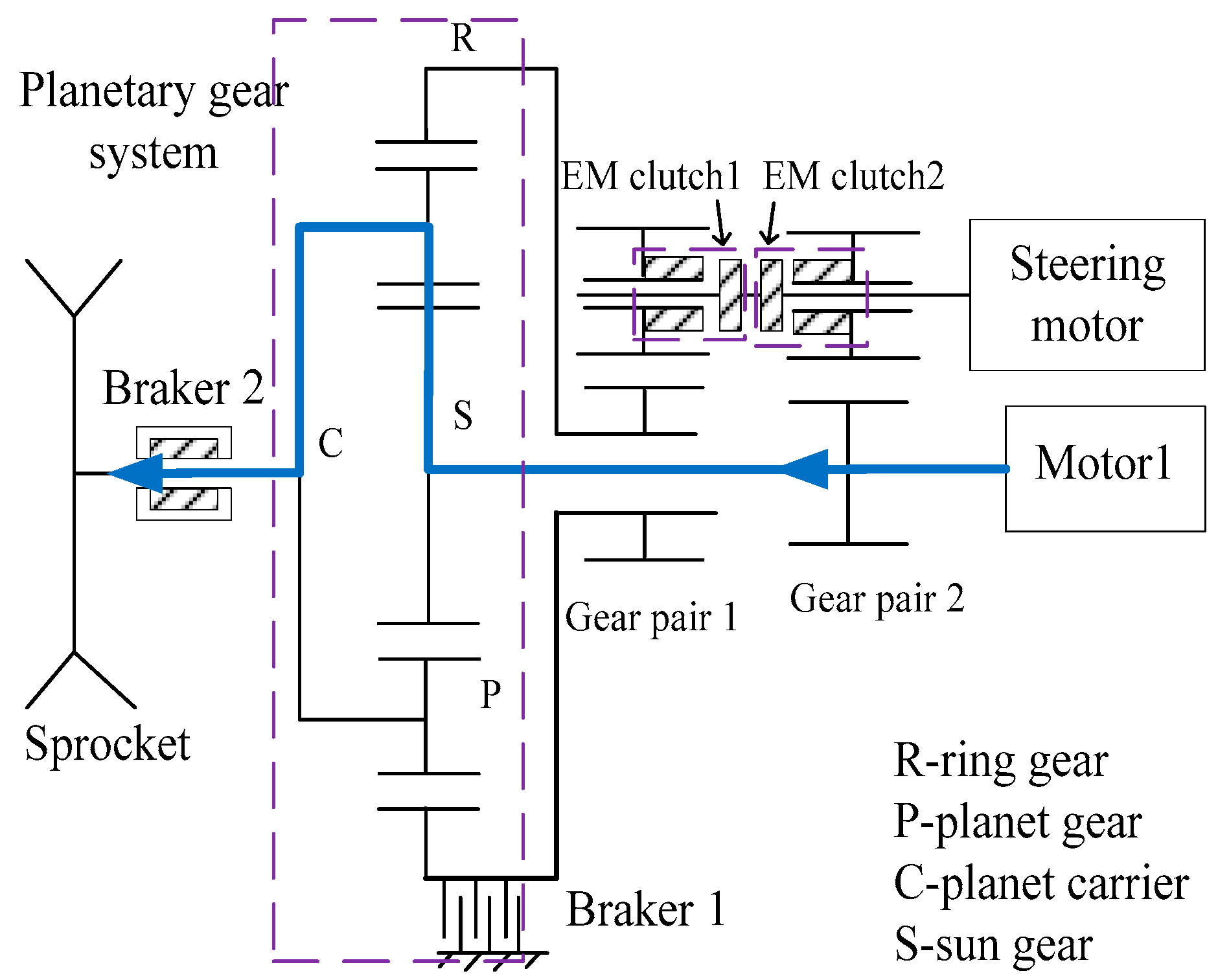
The planetary gear couplers consists of two electromagnetic (EM) clutches, two gear pairs and a planetary gear unit, which consists of a sun gear, a ring gear, a planet carrier and three planet gears, shown in Figure 3. Gear pair 1 contains gear 1 and gear 2 (ring gear), whereas gear pair 2 contains gear 3 and gear 4. It's worth noting that gear 1 and gear 3 are mounted on the steering motor shaft without a spline, transmitting the torque occurs only when one of the EM clutches is engaged. The dual motor coupling drive steering includes a single side coupling mode and a double side coupling mode. We take one side as an example, as shown in Figure 3.
When the vehicle is driving straight, the ring gear (R) is fixed by brake 1 while both the EM clutch 1 and the EM clutch 2 are disengaged. The power is transmitted to the sun gear (S) of the planetary gear unit (transmission ratio 6.35) from the propulsion motor, and outputted through the planet carrier (C) to the sprocket. During steering, if the torque or power does not meet the demand, the torque or the power is coupled by this planetary gear coupling device. The coupling mode includes torque coupling mode and speed coupling mode, as shown in Table 5.
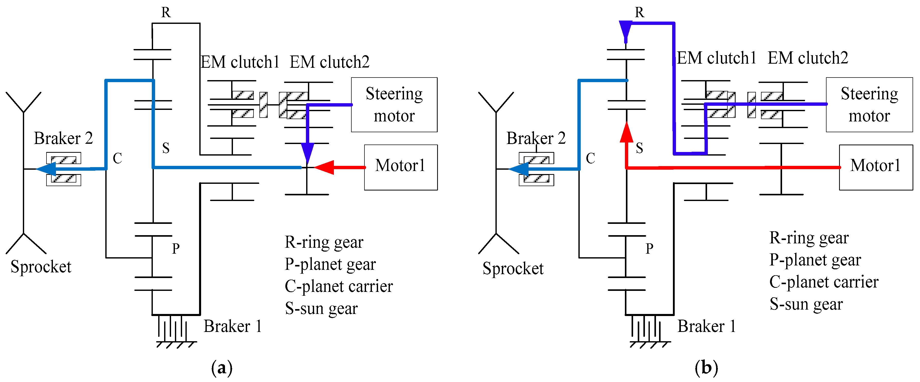
The torque coupling mode is active when the vehicle is turning in a small radius at low speed. In the torque coupling mode the EM clutch 1 is disconnected while the EM clutch 2 is engaged and brake 1 is disengaged. Then the torque of the steering motor and the propulsion motor are coupled to the sun gear (S) through the gear pair 2, transmitted to the sprocket through the planet carrier (C). The power transmission path is shown in Figure 4a.
The power coupling mode is active when the vehicle is turning in big radius at high speed. In the power coupling mode the EM clutch 1 is engaged while the EM clutch 2 is disconnected and the brake 1 is engaged. The power of the steering motor is transferred to ring gear (R) through the gear pair 1 and the power of propulsion motor is transmitted to the sun gear (S). Then the power is coupled and transmitted to the sprocket through the planet carrier (C). The power transmission path is shown in Figure 4b.
The torque and power output to the driving sprockets on both sides under different steering radius conditions with this coupling device are shown in Table 6. The performance of the vehicle without the coupling device is also shown in Table 6.
It can be seen from Table 3 and Table 6 that the maximum torque of the propulsion motor is 150 N·m, which cannot meet the steering requirement whereas with the coupling device a maximum torque of 280 N·m, can be transmitted from the propulsion motor to sprocket to meet the dynamic or stationary small-radius steering requirements. When the vehicle is turning in a big radius, the peak power of the motor is 40 kW without coupling, which is not enough, while with coupling, the vehicle can output a large enough power (60 kW at most) to meet the 8 B steering requirement shown in Table 3.
3.3. Planetary Geaer System Design
3.3.1. Selection and Preliminary Calculation
The planetary gear transmission type 2Z-X (A) (defined by the former Soviet Union), that is NGW type, is selected. The transmission ratio is 6.35. The number of teeth of each gear: sun gear Za = 17, ring gear Zb = 91, planetary gear Zc = 37, so the actual gear ratio i = 6.353 and the gear ratio error is 0.05%. The material of sun gear and planetary gear are 20CrMnTi, level 6 precision. The material of ring gear is 42CrMo, level 7 precision.
Calculate the gear module initially according to bending fatigue:
where is the formula coefficient, is the using coefficient, is the comprehensive coefficient, is the bending coefficient, is the tooth shape coefficient, is the tooth width coefficient. is the permissible stress. Therefore the gear module is 2.5. The centre distance is 70 mm with a spiral angle of 15.3589°.
3.3.2. Geometric Size Calculation
The geometric sizes of the sun gear (with subscript 1), planet gear (with subscript 2) and ring gear (with subscript 3) are shown in Table 7.
3.3.3. Checking of the Strength
To make sure the coupler can work in extreme condition, the teeth contact stress and the teeth bending strength is checked as shown in Table 8. The stress suffered by gear teeth is lower than the allowed value so the coupler can meet the strength requirements.
3.4. EM Clutch and EM Brake
According the maximum torque characteristics of steering motor and planetary gear coupler in Table 3, the maximum required torques of EM clutch 1 and EM clutch 2 in Figure 3 are 150 and 130 N·m, respectively. The overall size of the EM clutch 1 and EM clutch 2 is Φ = 90 mm × 100 mm. The maximum required braking torques and the size of the electromagnetic brake is 1500 N·m and Φ = 310 mm × 55 mm, respectively. The important design parameters of the electromagnetic clutches and the electromagnetic brakes are proposed for manufacture. Based on the above calculations, the overall size of the coupling device is designed as 468 mm × 364 mm × 378 mm.
4. Control Strategy
4.1. Driver Inputs Modeling
The input angle signal of the steering wheel displacement is shown in Figure 5. According to different steering wheel angle signals, the desired turning radius can be calculated.
The displacement of acceleration pedal or brake pedal is assumed to be linear to the output torque of motor. The control coefficient of acceleration (A) and brake pedal displacement signal (D) are given as follows:
where α and β are the displacements of acceleration and brake pedals, respectively. and are the free displacements of acceleration and brake pedals, respectively. and are the maximum displacements of acceleration and brake pedals, respectively. A is in the range from 0 to 1, where the output torque of propulsion motor is in the range from 0 to Tmax. And D is in the range from −1 to 0, where the output torque of propulsion motor is in the range from Tmax to 0.
4.2. Torque Distribution Strategy Based on Speed
A torque distribution control strategy based on speed is proposed and shown in Figure 6. According to A, B and steering wheel angle signals, based on the above calculation, the torque and rotation speed desired can be determined. The coupling distribution controller is used to regulate the torque of each motor to track the driver inputs based on the real-time rotation speed (nL-real/nR-real) and the revised torque (ΔT1/ΔT2) from the slip-ratio controller. The torque generated by each motor is coupled through the electromechanical coupling device and transmitted to the sprocket.
4.2.1. Ideal Vehicle Body Model
According to the dynamic analysis, the ideal vehicle model can be summarized as follows:
where ω is the desired yaw rate, VL,R is the left or right side track speed in center steering which can be calculated from the accelerator pedal position, vdes is the desired vehicle speed, Rdes is the ideal steering radius.
The desired vehicle speed and ideal steering radius can be determined by driver model. These signal are inputs to the ideal vehicle body model and the desired sprocket rotation speed and torque are calculated.
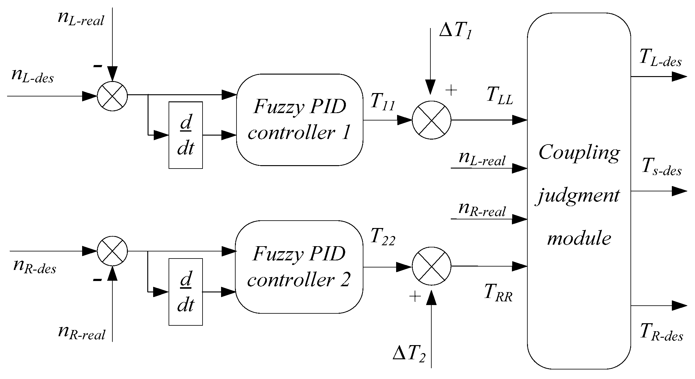
4.2.2. Coupling Distribution Controller
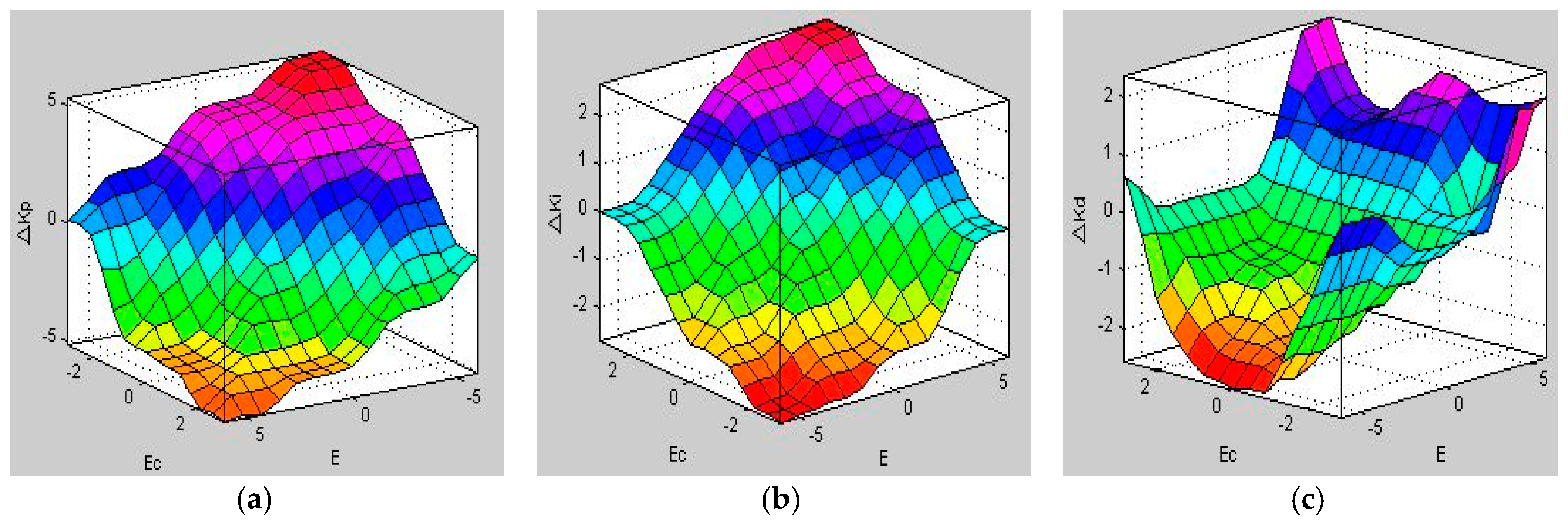
Figure 7 shows the workflow of the coupling distribution controller. The controller receives the signals (Tdes, ndes) calculated from the ideal vehicle model. Using the fuzzy proportion integration differentiation (PID) controller based on the error between the reference rotational speed and the actual rotational speed to produce the torque T11. The fuzzy rules is shown in Figure 8a–c. The torque signal (TLL) sent to the coupling judgment module is given as follows:
where ΔT1 is obtained by the slip ratio controller, which will be introduced in next section. Similarly, the torque signal (TRR) sent to coupling judgment module is given as follows:
The flowchart of the coupling judgment module is shown in Figure 9. Depending on the different TLL and TRR obtained, the module will output different torque commands to the motor controller. When the required torque and power does not exceed their peak value, the steering motor does not work, Ts = 0. When the required torque exceeds the peak torque of the propulsion motor, the steering motor operates to generate additional torque to meet the torque requirements. When the power of motor is insufficient, the power coupling mode is active, the steering motor generates the relevant torque to meet the coupling conditions, and output enough power.
4.2.3. Slip Ratio Controller
Usually, tracked vehicles turns are accompanied by a slip phenomenon:
where n = rω is the sprocket rotation speed, u is the track longitudinal speed, generally u = V.
In order to improve the tracked vehicle steering stability and use the energy efficiently, the slip ratio is controlled within a reasonable range. The choice of slip ratio is related to the road parameters, and normally sdes = 0.15 for an asphalt road. The slip ratio controller is designed based on the fuzzy PID control method (similar to torque controller mentioned above) to maintain the actual slip ratio closed to the ideal slip ratio, as shown in Figure 10. The actual slip ratio is calculated from Equation (13).
5. Modeling and Simulation Results
The steering co-simulation model shown in Figure 6 is built by multi-body software Recurdyn and control software Matlab/Simulink. The vehicle model and ground model are developed in Recurdyn as shown in Figure 11. The driver inputs model, the control model based on speed and the motor system model are developed in Simulink. The control module in Recurdyn is seamlessly interfaced with Matlab/Simulink. The parameters of the dynamic simulation parameters are shown in Table 9. The reaction characteristic of motors can be automatically generated by motor controller model in Simulink and transferred to Recurdyn as input of the motor.
5.1. Center Steering
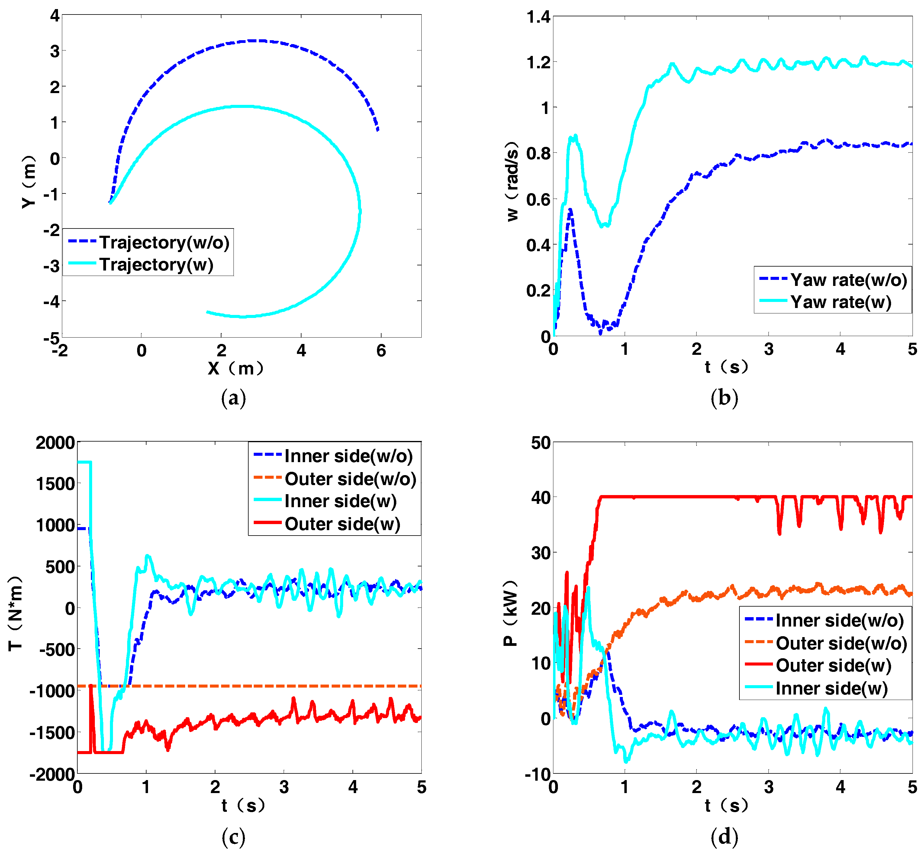
When the steering wheel is turned to the left, the accelerator pedal is pushed to the bottom, the vehicle begins to turn from its static position. The comparative trajectory is shown in Figure 12a. The vehicle without coupling device turns slowly due to its insufficient output torque. When the coupling device is used, the yaw rate of the vehicle increases rapidly to the ideal value (1.3 rad/s) whereas when the coupling device is not used the yaw rate gradually increases to 0.8 rad/s as shown in Figure 12b. It can be seen from Figure 12c that the vehicle with the coupling device outputs a larger torque in the initial movement to meet the needs of small-radius dynamic steering. As the steering enters the steady state, the output torque decreases and finally tends to a constant value. The power generated by sprockets is shown in Figure 12d. The power output is increased with coupling, but has a small value as a whole.
5.2. 0.5 B Steering
The steering wheel is manipulated to output R = 0.5 B, the accelerator pedal is pushed to the bottom and the vehicle begins to turn from its static position. The trajectory of the vehicle is shown in Figure 13a. If the coupling device is not added, due to the limited torque, the sprocket cannot always generate the required torque, so the torque on both sides is always at the upper limit (150 N·m). In Figure 13b it can be seen that the yaw rate is about 1.2 rad/s when the vehicle is turning with the coupling device, but only 0.8 rad/s without it. Figure 13c shows that during the initial dynamic steering phase, the required torque is quite large. The vehicle with the coupling device can satisfy the torque requirement and the torque tends to a smaller constant value in steady state. The power generated by the sprockets is shown in Figure 13d. The power on the outer side increases with the coupling device and the power on the inner side is slightly reduced, but the overall power is not very large.
5.3. 2 B Steering
The steering wheel is manipulated to output R = 0.5 B, the accelerator pedal is pushed to the bottom and the vehicle begins to turn from its static position. The trajectory of the vehicle is shown in Figure 14a. It can be seen that the vehicle understeer is improved with the coupling device. From Figure 14b, we can see that finally the yaw rate of the vehicle is 1.2 rad/s, which is close to the theoretical value, and the yaw rate of the vehicle without the coupling device is only 0.8 rad/s. As shown in Figure 14c, since the coupling device is used, the outer side output torque of the vehicle is increased, and the inter side sprocket regenerates braking torque. The power generated by the outer sprockets and regenerated by the inter sprocket are shown in Figure 14d. This time the inner motor regenerates braking power, while the outer motor output the maximum power. Although the theoretical torque and power don’t exceed the maximum value according to Table 3, the torque and power of the outer side sprocket in simulation is much larger than theoretically calculated, meaning the steering resistance moment may be larger than we expected.
5.4. 8 B Steering
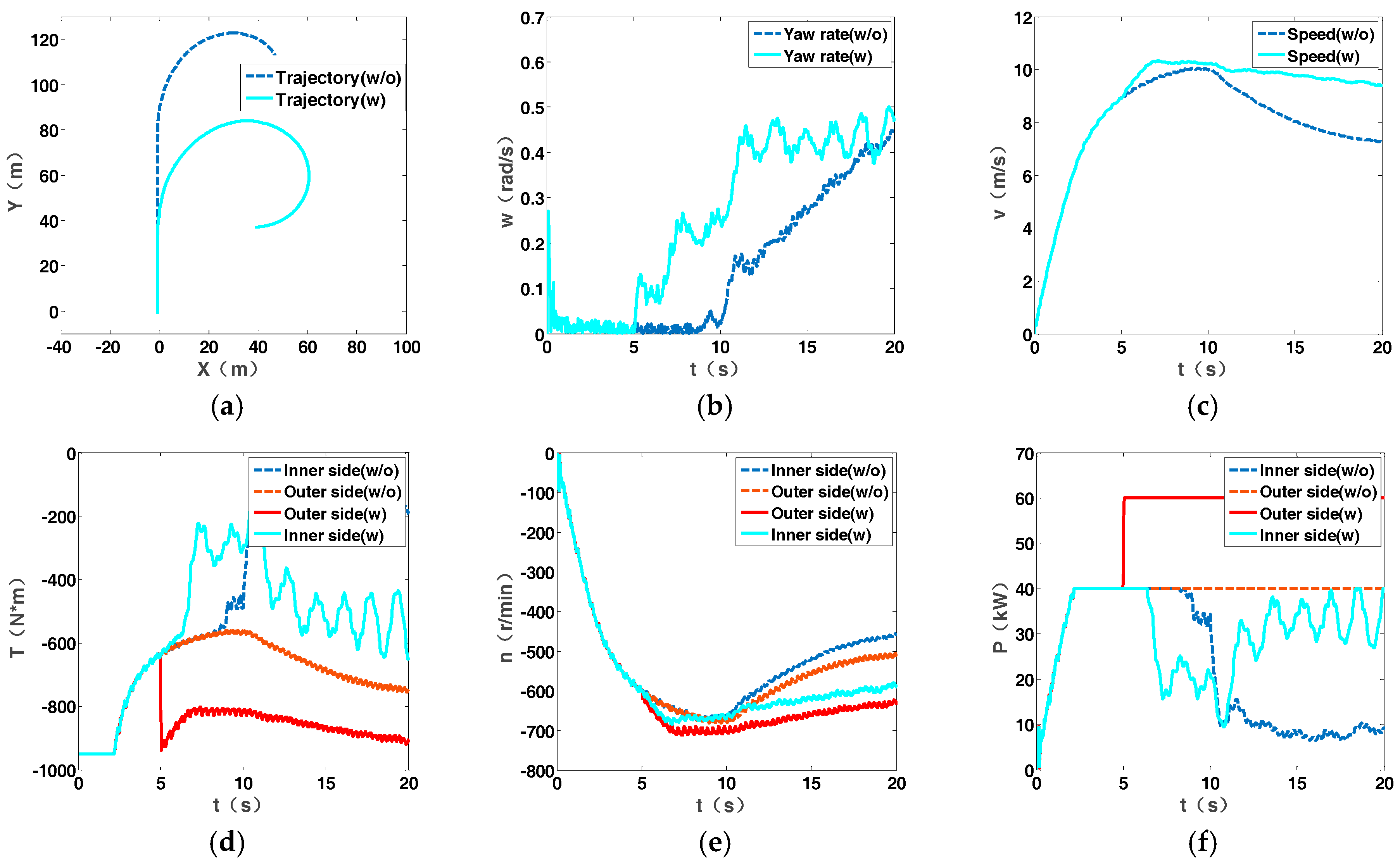
The steering wheel is manipulated to output R = 8 B, and the accelerator pedal is controlled to make vehicle accelerate from 0 to 30 km/h to drive steering. The trajectory of the vehicle is shown in Figure 15a. The understeer characteristic of the vehicle is improved. The yaw rate of the vehicle shown in Figure 15b is not as large as that in small-radius steering due to the high speed of the vehicle. The power of the outer sprocket is larger thanks to the coupling device, while the power of the vehicle without the coupling device is always at maximum value as shown in Figure 15f. Without the coupling device, the vehicle speed decreases rapidly, as shown in Figure 15c. The torque and the rotation speed of the sprocket are shown in Figure 15d,e.
6. Conclusions
In this paper, we found that the torque and power required by the propulsion motor are quite large according to the dynamic analysis of the 2METV. Therefore, a new steering coupling device is designed without increasing the peak torque or power of the propulsion motor. The device consists of a planetary gear system, two gear pairs, two electromagnetic clutches and a braker. By coupling the torque or power of the steering motor and the propulsion motor, the torque or power input to the sprocket is increased to meet the steering performance requirements in different radius. Based on this, a torque-coupled distribution strategy based on speed is proposed. The simulation in RecurDyn and Matlab/Simulink shows that the coupling device can improve the output torque or power of the sprockets, and using the proposed control strategy can achieve the better trajectory following.
Acknowledgments
This work was supported by the National Natural Science Foundation of China for financially supporting this project (51475045).
Author Contributions
Li Zhai proposed the innovation of the overall system and designed the control methods, Hong Huang are responsible for the design of coupled systems and the simulation of the system, Steven Kavuma performed the simulation of control methods. Li Zhai and Hong Huang wrote the manuscript and Steven Kavuma polished the manuscript. All authors read and approved the manuscript.
Conflicts of Interest
The authors declare no conflict of interest.
References
- Zhai, L.; Sun, T.M.; Wang, Q.N.; Wang, J. Lateral stability control of dynamic steering for dual motor drive high speed tracked vehicle. Int. J. Autom. Technol. 2016, 17, 1079–1090. [Google Scholar] [CrossRef]
- Ketting, M.; Frohner, F.; Wottawah, V. Drive Chain for Tracked Vehicle. U.S. Patent 6142588 A, 7 November 2000. [Google Scholar]
- LI, J.; Zhang, H.; Meng, H.; Tang, R. Research of tracked vehicle compliance simulation. Armor. Veh. Engine 2003, 92, 4–7. [Google Scholar]
- Kim, M.S.; Woo, Y.H. Robust design optimization of the dynamic responses of a tracked vehicle system. Int. J. Autom. Technol. 2013, 14, 47–51. [Google Scholar] [CrossRef]
- Lu, L.; Sun, F.; Zhai, L. Steering performance simulation for electric drive tracked vehicle based on Matlab Simulink. Acta Armamentarii 2016, 27, 69–74. [Google Scholar]
- Zang, K.M.; Liao, Z.L.; LI, H. Study on general technology of the tank electric transmission. Veh. Power Technol. 2007, 1, 5–12. [Google Scholar]
- Wang, H.; Huang, Y.; Khajepour, A.; He, H.; Cao, D. A novel energy management for hybrid off-road vehicles without future driving cycles as a priori. Energy 2017, in press. [Google Scholar] [CrossRef]
- Wang, H.; Huang, Y.; Khajepour, A.; Song, Q. Model predictive control-based energy management strategy for a series hybrid electric tracked vehicle. Appl. Energy 2016, 182, 105–114. [Google Scholar] [CrossRef]
- Hong-Cai, L.I.; Yan, Q.D.; Song, W.Q.; Chen, J.X. Research on electric transmission program of steering power's mechanical recycle of tracklayer. J. Mach. Des. 2011, 28, 60–64. [Google Scholar]
- Zhai, L.; Sun, F.C.; Gu, Z.L.; Zhang, C.N. Steering control strategy of electronic differential speed in electric drive tracked vehicle. Trans. Beijing Inst. Technol. 2009, 2, 006. [Google Scholar]
- Gao, M.; Hu, J.; Peng, Z. Study on optimization for transmission system of electric drive tracked vehicles. Energy Proced. 2017, 105, 2971–2976. [Google Scholar] [CrossRef]
- Sun, F.C.; Chen, S.Y.; Zhang, C.N. Steering dynamic performance of an electric transmission tracked vehicle based on rotating speed control. Defin. Technol. 2006, 2, 7–13. [Google Scholar]
- Sheng, H.; Li, C.M.; Xu, Y.; Du, M.G.; Ma, T. Research on composite braking technology for electric drive high speed tracked vehicle. Adv. Eng. Res. 2017, 105, 594–602. [Google Scholar]
- Thompson, R.W. Drive Configuration for Skid Steered Vehicles. U.S. Patent 8485286, 16 July 2013. [Google Scholar]
- Purdy, D.J.; Simner, D.; Diskett, D.; Duncan, A.; Wormell, P.J.H.; Stonier, C. An experimental and theoretical investigation into the roll-over of tracked vehicles. Proc. Inst. Mechan. Eng. Part D J. Autom. Eng. 2015, 230, 291–307. [Google Scholar] [CrossRef]
- Zaunberger, F.X. Electro-Mechanical Drive System for a Full-Track Vehicle. U.S. Patent 4998591, 3 December 1991. [Google Scholar]
- Gai, J.; Huang, S.; Zhou, G.; Li, S. Design method of power coupling mechanism scheme for double side motors coupling drive transmission. China Mechan. Eng. 2014, 13, 1739–1743. [Google Scholar]
- Jia, X.P.; Jun, M.A.; Fan, S.G.; Kui-Long, Y.U. Simulation of coupling mechanism for electric-drive off-road vehicle. Veh. Power Technol. 2014, 136, 6–10. [Google Scholar]
- Wang, Q.N. Study on Steering Stability Control for Dual Motor Drivetracked Vehicle. Master’s Thesis, Beijing Institute of Technology, Beijing, China, 2014. [Google Scholar]
- Aripin, M.K.; Sam, Y.M.; Danapalasingam, K.A.; Peng, K.; Hamzah, N.; Ismail, M.F. A review of active yaw control system for vehicle handling and stability enhancement. Int. J. Veh. Technol. 2014, 1–4, 1–15. [Google Scholar] [CrossRef]
- Zhai, L.; Sun, T.; Wang, J. Electronic stability control based on motor driving and braking torque distribution for a four in-wheel motor drive electric vehicle. IEEE Trans. Veh. Technol. 2016, 65, 4726–4739. [Google Scholar] [CrossRef]
- Taratorkin, I.; Derzhanskii, V.; Taratorkin, A. Experimental determination of kinematic and power parameters at the tracked vehicle turning. Proced. Eng. 2016, 150, 1368–1377. [Google Scholar] [CrossRef]
Figure 1.
Force analysis: (a) R ≤ 0.5 B steering; (b) R > 0.5 B steering.
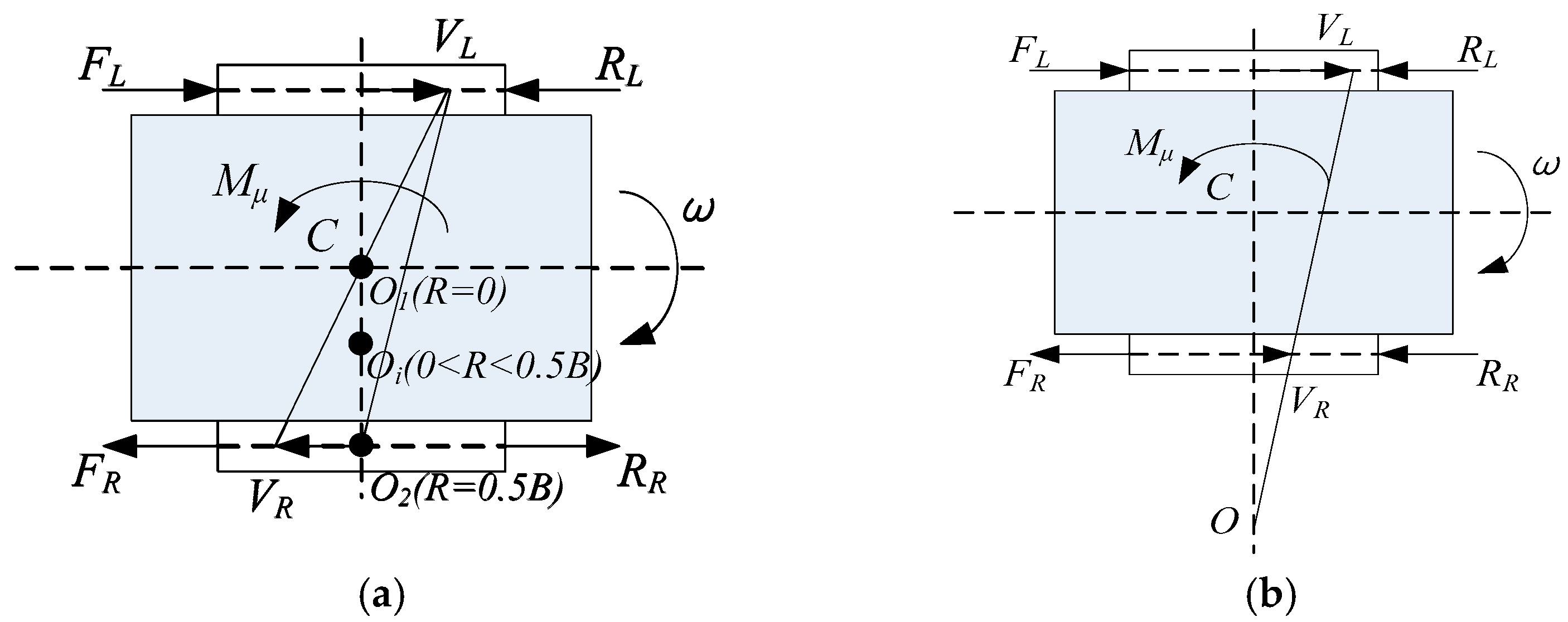
Figure 2.
Steering coupling drive system configuration.

Figure 3.
Components of the planetary gear coupler.

Figure 4.
(a) Torque coupling transmission mode; (b) Power coupling transmission mode.

Figure 5.
Input angle signal of steering wheel.
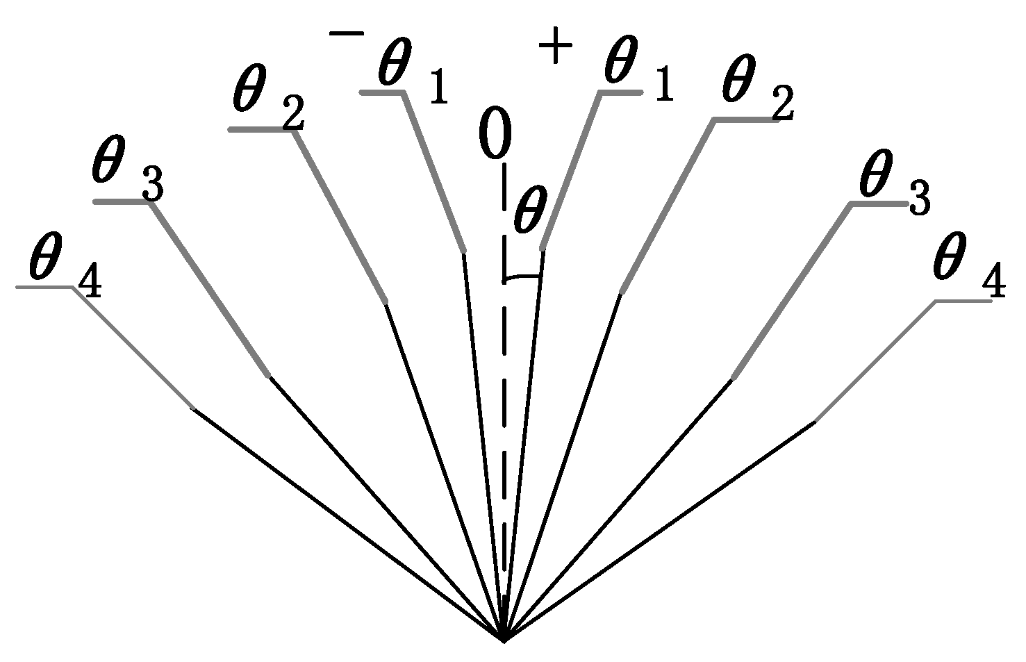
Figure 6.
Torque distribution strategy based on speed.
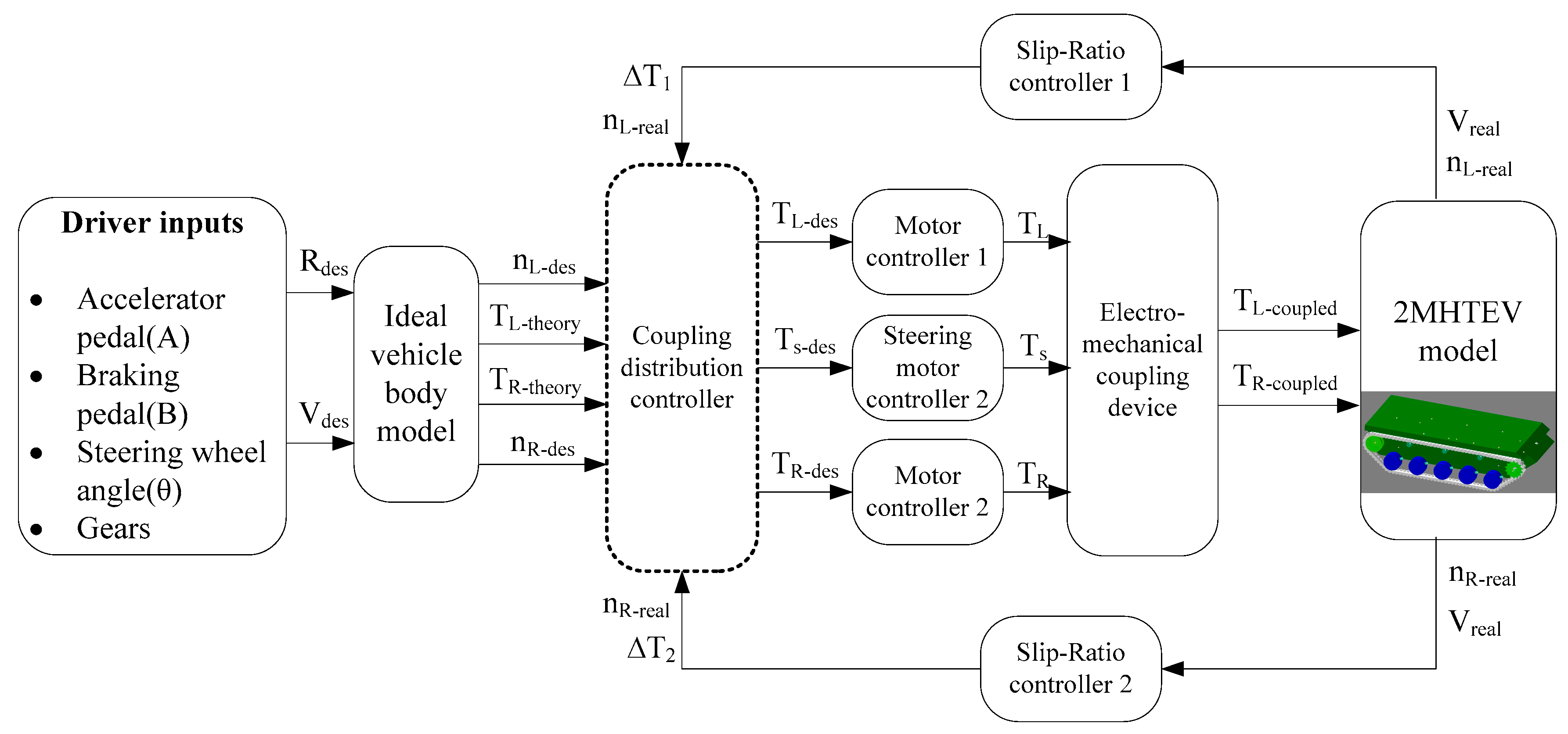
Figure 7.
Coupling distribution controller.

Figure 8.
Fuzzy rules: (a) Kp rules (b) Ki rules (c) Kd rules.

Figure 9.
Flowchart of the coupling judgment module.
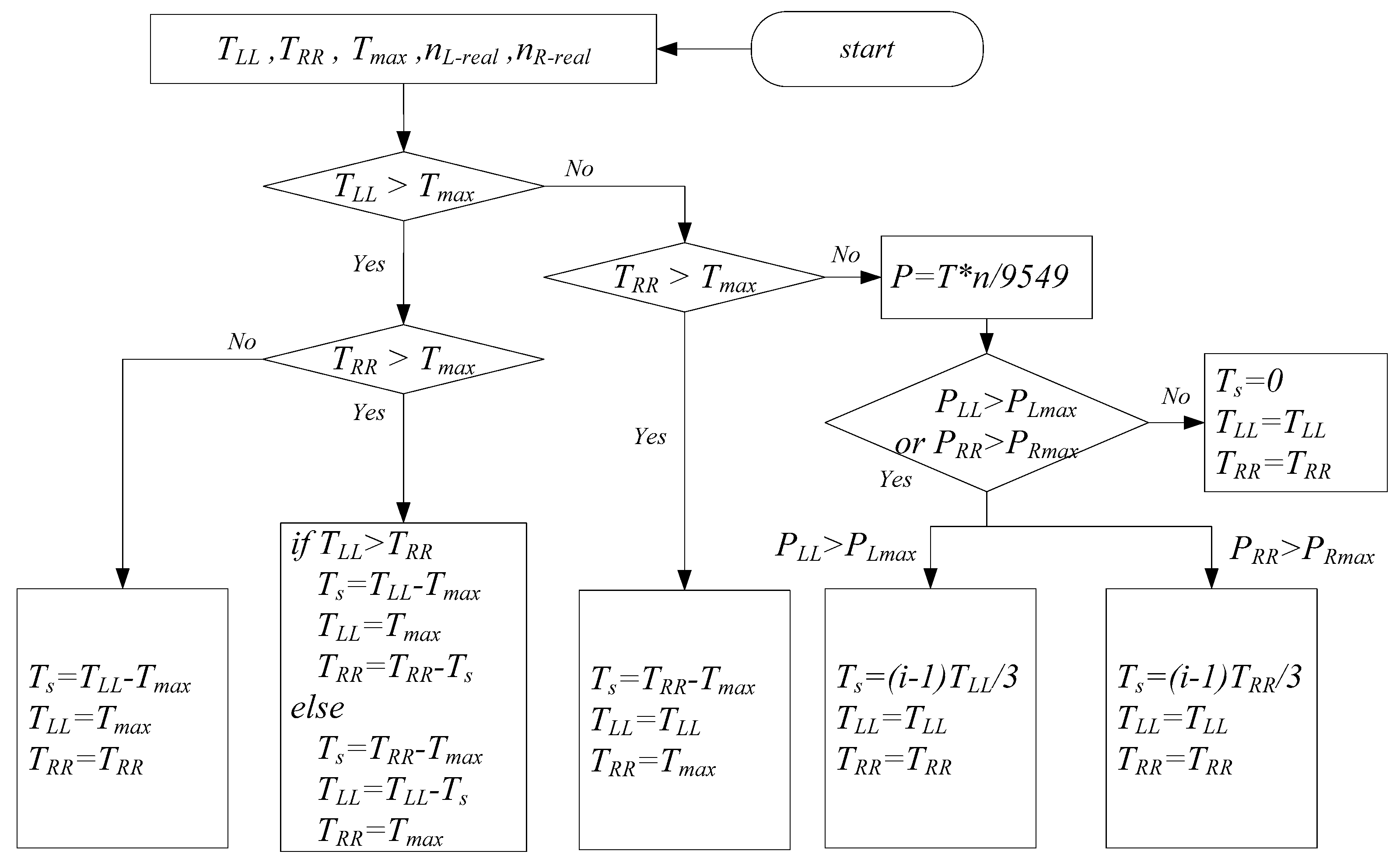
Figure 10.
Slip ratio controller.
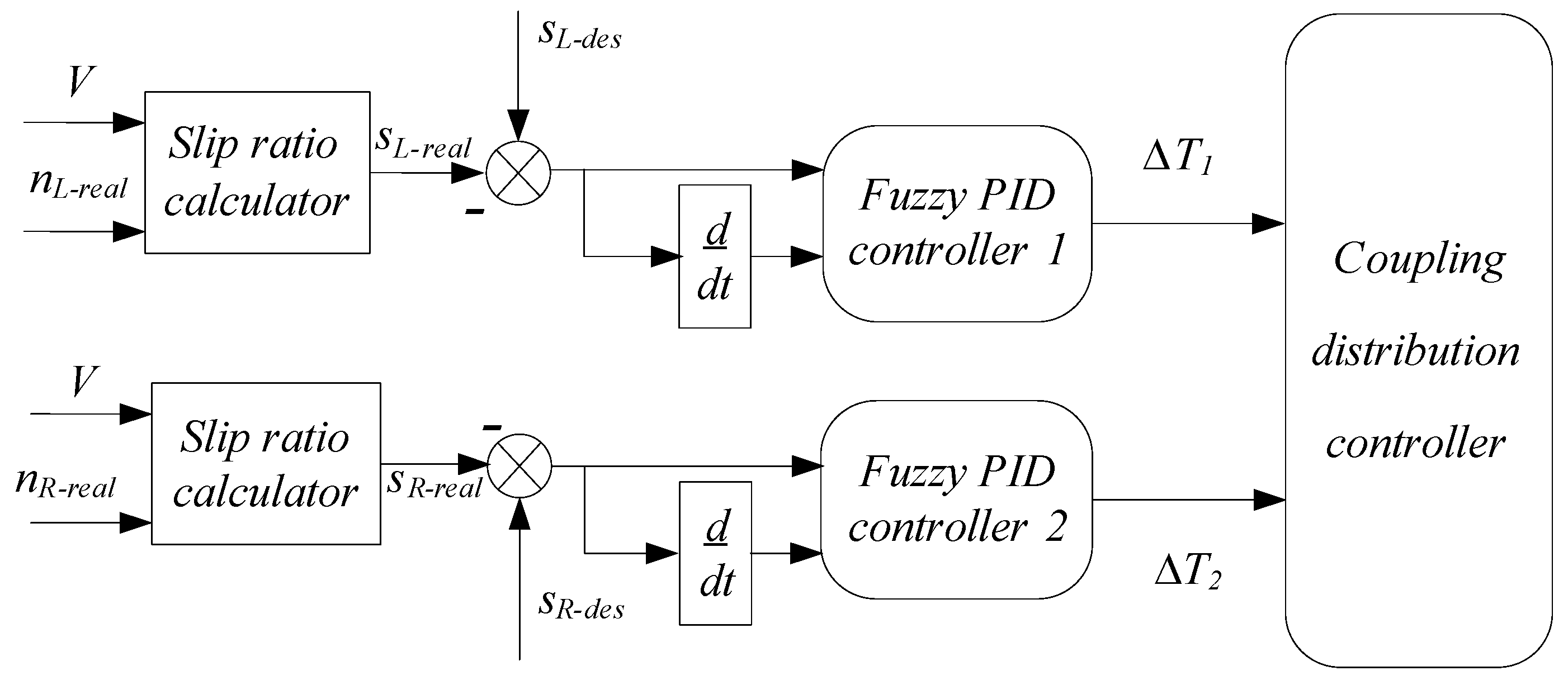
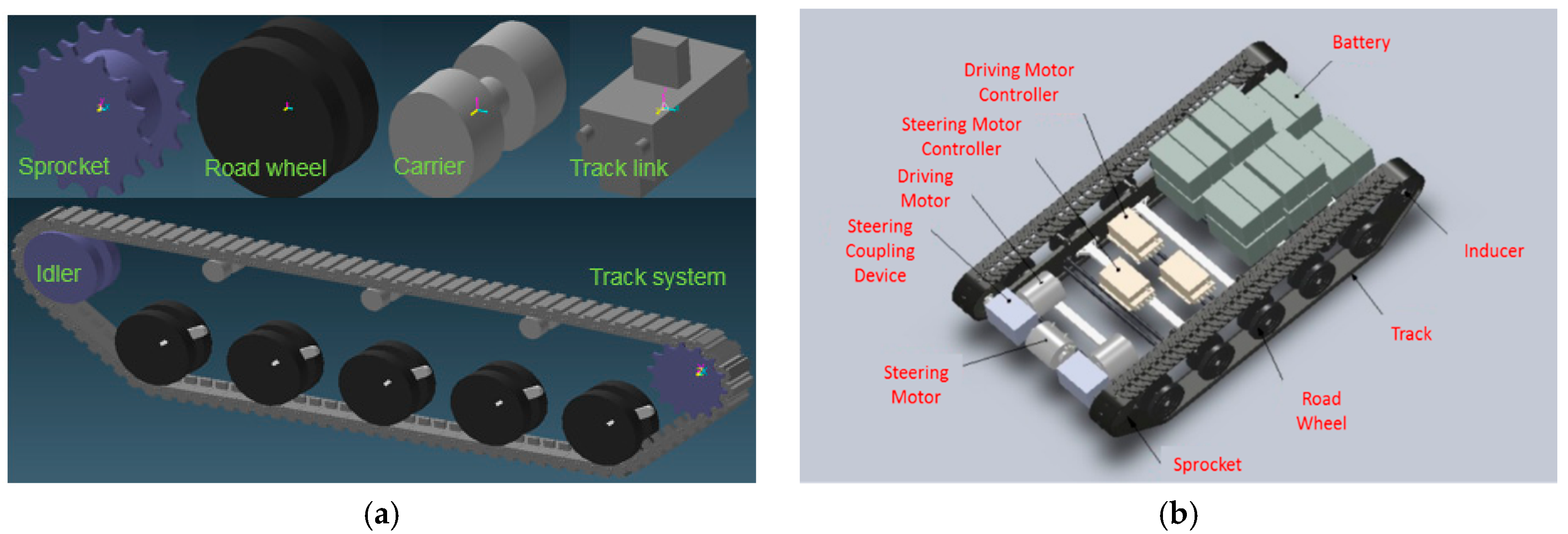
Figure 11.
(a) Track modeling; (b) Vehicle modeling.

Figure 12.
Simulation results of center steering: (a) Trajectory; (b) Vehicle yaw rate; (c) Sprocket torque; (d) Sprocket power.
Figure 12.
Simulation results of center steering: (a) Trajectory; (b) Vehicle yaw rate; (c) Sprocket torque; (d) Sprocket power.
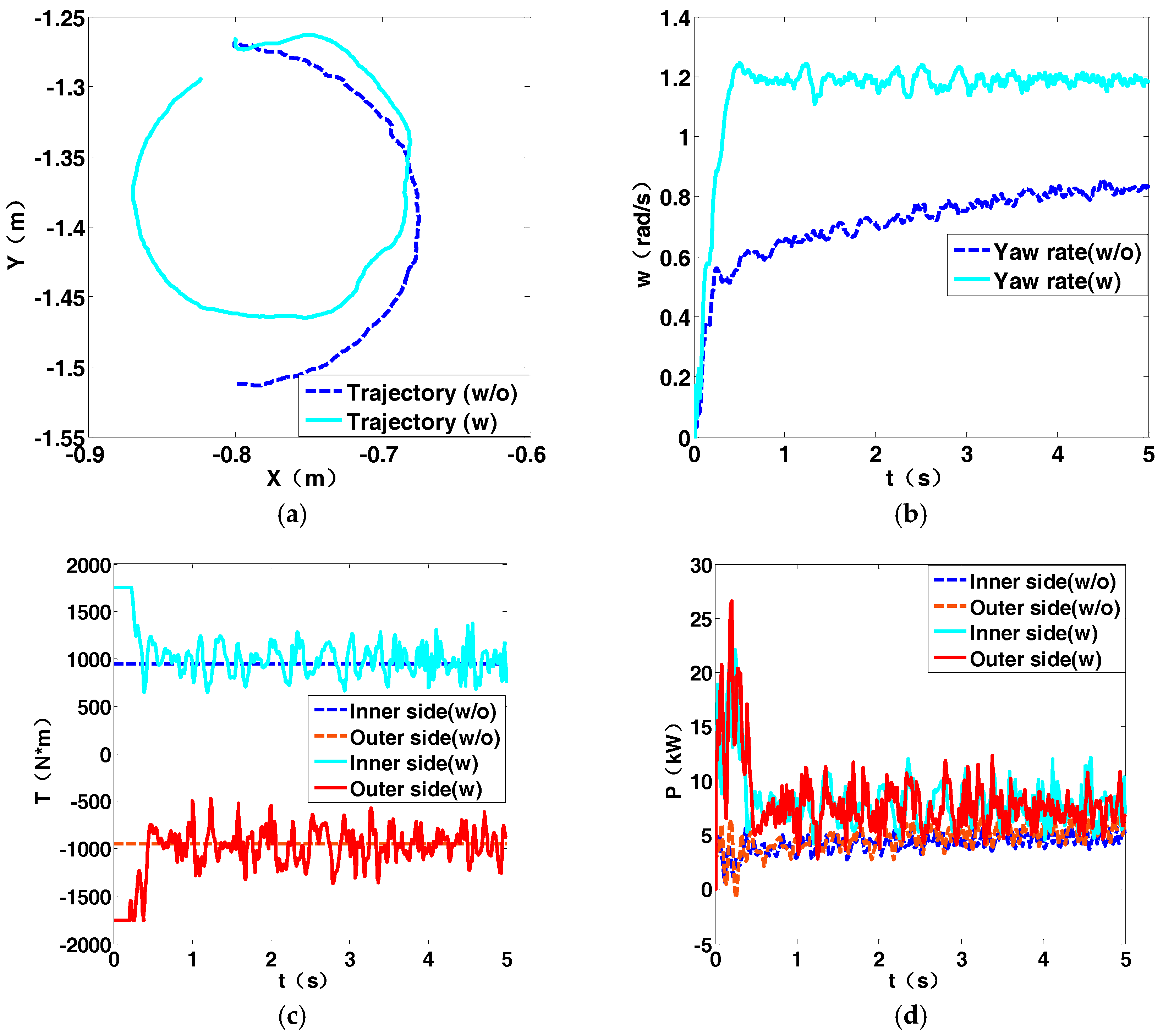
Figure 13.
Simulation results of 0.5 B steering: (a) Trajectory; (b) Vehicle yaw rate; (c) Sprocket torque; (d) Sprocket power.
Figure 13.
Simulation results of 0.5 B steering: (a) Trajectory; (b) Vehicle yaw rate; (c) Sprocket torque; (d) Sprocket power.
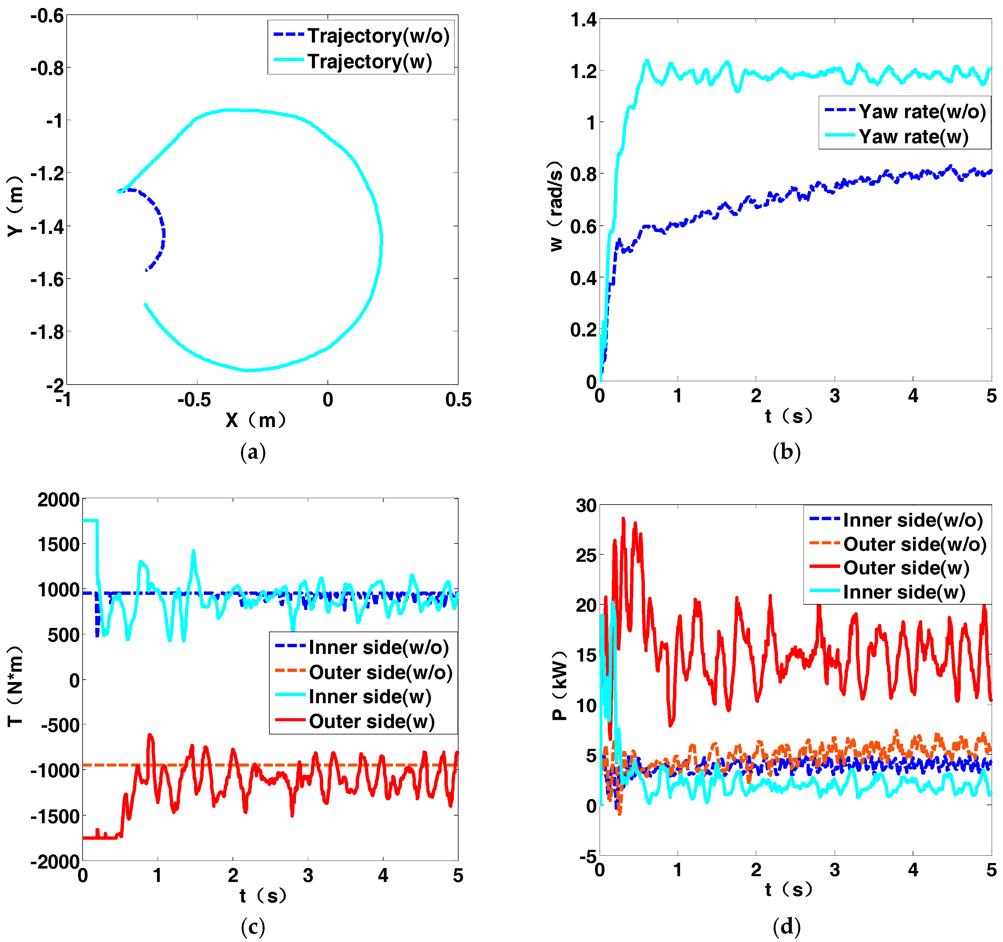
Figure 14.
Simulation results of 2 B steering: (a) Trajectory; (b) Vehicle yaw rate; (c) Sprocket torque; (d) Sprocket power.
Figure 14.
Simulation results of 2 B steering: (a) Trajectory; (b) Vehicle yaw rate; (c) Sprocket torque; (d) Sprocket power.

Figure 15.
Simulation results of 8 B steering: (a) Trajectory; (b) Vehicle yaw rate; (c) Vehicle speed; (d) Sprocket torque; (e) Sprocket rotation speed (f) Sprocket power.
Figure 15.
Simulation results of 8 B steering: (a) Trajectory; (b) Vehicle yaw rate; (c) Vehicle speed; (d) Sprocket torque; (e) Sprocket rotation speed (f) Sprocket power.


Table 1.
Vehicle parameters.
| Parameters | Value |
|---|---|
| Vehicle tread, B (m) | 1.3 |
| Ground contact length, L (m) | 1.7 |
| Rolling resistance coefficient, f | 0.04 |
| Transmission efficiency, η | 0.9 |
| Drive ratio, ig | 6.35 |
| Mass of vehicle, m (kg) | 2000 |
| Mass gain coefficient, δ | 1.5 |
| Moment of inertia, J (kg/m2) | 3000 |
Table 2.
Motor parameters.
| Parameters | Rated Power (kW) | Rated Torque (N·m) | Rated Speed (r/min) | Maximum Power (kW) | Maximum Torque (N·m) | Maximum Speed (r/min) |
|---|---|---|---|---|---|---|
| Value | 20 | 64 | 3000 | 40 | 150 | 9000 |
Table 3.
Dynamic and stationary steering torque and power required by two motors.
| Situation | R (mm) | TL (N·m) | TR (N·m) | nL (r/min) | nR (r/min) | PL (kW) | PR (kW) | V (km/h) |
|---|---|---|---|---|---|---|---|---|
| Dynamic | 0 | 272 | 272 | 344 | 344 | 9.8 | 9.8 | 0 |
| 0.2 B | 279 | 252 | 482 | 206 | 14.1 | 5.5 | 1.22 | |
| 0.5 B | 258 | 181 | 688 | 0 | 18.6 | 0 | 3.06 | |
| Stationary | 0 | 192 | 192 | 344 | 344 | 6.9 | 6.9 | 0 |
| 0.2 B | 187 | 187 | 482 | 206 | 9.4 | 4.0 | 1.22 | |
| 0.5 B | 179 | 168 | 688 | 0 | 12.9 | 0 | 3.06 | |
| 2 B | 148 | −127 | 1720 | 1032 | 26.6 | −13.7 | 12.2 | |
| 5 B | 111 | −90 | 3096 | 3784 | 43.9 | −29.2 | 30.6 | |
| 8 B | 90 | −69 | 5847 | 5159 | 54.8 | −37.2 | 49.0 | |
| 10 B | 80 | −59 | 7223 | 6535 | 60.3 | −40.5 | 61.2 |
Table 4.
Steering motor parameters.
| Parameters | Rated Power (kW) | Rated Torque (N·m) | Rated Speed (r/min) | Maximum Power (kW) | Maximum Torque (N·m) | Maximum Speed (r/min) |
|---|---|---|---|---|---|---|
| Value | 10 | 160 | 600 | 20 | 300 | 1200 |
Table 5.
Coupling mode and the operation of each component.
| Mode | Braker 1 | EM Clutch 1 | EM Clutch 2 | Steering Motor | Propulsion Motor |
|---|---|---|---|---|---|
| Straight | engaged | disconnected | disconnected | off | working |
| Torque coupling | engaged | disconnected | combined | working | working |
| Power coupling | disengaged | combined | disconnected | working | working |
Table 6.
Motors’ condition comparison between the vehicle with and without coupling device.
| Radius | Coupling | TL (N·m) | TR (N·m) | Ts (N·m) | PL (kW) | PR (kW) | Ps (kW) | nL (r/min) | nR (r/min) | ns (r/min) |
|---|---|---|---|---|---|---|---|---|---|---|
| 0 B (dynamic) | without | 150 | 150 | 0 | 5.4 | 5.4 | 0 | 344 | 344 | 0 |
| with | 150 | 150 | 260 | 5.4 | 5.4 | 9.4 | 344 | |||
| 0.5 B (dynamic) | without | 150 | 150 | 0 | 10.8 | 0 | 0 | 688 | 0 | 0 |
| with | 150 | 150 | 108 | 10.8 | 0 | 7.8 | 688 | |||
| 0 B (stationary) | without | 150 | 150 | 0 | 5.4 | 5.4 | 0 | 344 | 344 | 0 |
| with | 150 | 150 | 84 | 5.4 | 5.4 | 3 | 344 | |||
| 0.5 B (stationary) | without | 150 | 150 | 0 | 10.8 | 0 | 0 | 688 | 0 | 0 |
| with | 150 | 150 | 29 | 10.8 | 0 | 2.1 | 688 | |||
| 2 B (stationary) | without | 148 | −127 | 0 | 26.7 | −13.7 | 0 | 1720 | 1032 | 0 |
| with | - | - | - | - | - | - | - | |||
| 8 B (stationary) | without | 90 | −69 | 0 | 40.0 | −27.1 | 0 | 4244 | 3744 | 0 |
| with | 90 | −69 | 150 | 54.8 | −37.1 | 14.8 | 4244 | 5129 | 942 |
Table 7.
Geometric sizes of each gear pair (mm).
| Gear Pair | Reference Circle Diameter (d) | Basic Circle Diameter (db) | Tip Circle Diameter (da) | Root Circle Diameter (df) | Breadth of Tooth (b) |
|---|---|---|---|---|---|
| External gear pair | d1 = 44.074 d2 = 95.926 | db1 = 41.234 db2 = 89.922 | da1 = 49.074 da2 = 100.926 | df1 = 37.824 df2 = 89.676 | bsun = 43 bplanet = 48 |
| Internal gear pair | d2 = 95.926 d3 = 235.926 | db2 = 89.922 db3 = 221.159 | da2 = 100.926 da3 = 231.320 | df2 = 89.676 df3 = 242.176 | bplanet = 48 bring = 43 |
Table 8.
Checking of each gear pair (MPa).
| Checking Pair | σH1 | σH2 | σF1 | σF2 | σHP1 (allowed) | σHP2 (allowed) | σFP1 (allowed) | σFP2 (allowed) | Checking |
|---|---|---|---|---|---|---|---|---|---|
| External gear pair (teeth contact stress) | 1162.8 | 1162.8 | - | - | 1566.1 | 1562.3 | - | - | σH1 ≤ σHP1 σH2 ≤ σHP2 |
| External gear pair (teeth bending strength) | - | - | 340.2 | 295.1 | - | - | 686.5 | 672.0 | σF1 ≤ σFP1 σF2 ≤ σFP2 |
| Internal gear pair (teeth contact stress) | 434.6 | 434.6 | - | - | 1818.9 | 793.6 | - | - | σH1 ≤ σHP1 σH2 ≤ σHP2 |
| Internal gear pair (teeth bending strength) | - | - | 233.2 | 228.9 | - | - | 588.0 | 383.3 | σH1 ≤ σHP1 σH2 ≤ σHP2 |
Table 9.
Dynamic simulation parameters.
| Component | Number | Inertia (kg·mm²) | Stiffness Coefficient | Damping Coefficient |
|---|---|---|---|---|
| Sprocket | 2 | 279,379 | 18,000 | 10 |
| Road Wheel | 10 | 685,898 | 12,000 | 10 |
| Carrier | 6 | 5121 | 15,000 | 10 |
| Track link | 198 | 1989 | 9000 | 10 |
| Track subsystem | - | - | 1,600,000 | 10,000 |
© 2017 by the authors. Licensee MDPI, Basel, Switzerland. This article is an open access article distributed under the terms and conditions of the Creative Commons Attribution (CC BY) license (http://creativecommons.org/licenses/by/4.0/).
Share and Cite
MDPI and ACS Style
Zhai, L.; Huang, H.; Kavuma, S. Investigation on a Power Coupling Steering System for Dual-Motor Drive Tracked Vehicles Based on Speed Control. Energies 2017, 10, 1118. https://doi.org/10.3390/en10081118
AMA Style
Zhai L, Huang H, Kavuma S. Investigation on a Power Coupling Steering System for Dual-Motor Drive Tracked Vehicles Based on Speed Control. Energies. 2017; 10(8):1118. https://doi.org/10.3390/en10081118
Chicago/Turabian StyleZhai, Li, Hong Huang, and Steven Kavuma. 2017. "Investigation on a Power Coupling Steering System for Dual-Motor Drive Tracked Vehicles Based on Speed Control" Energies 10, no. 8: 1118. https://doi.org/10.3390/en10081118
Note that from the first issue of 2016, this journal uses article numbers instead of page numbers. See further details here.