Electret Length Optimization of Output Power for Double-End Fixed Beam Out-of-Plane Electret-Based Vibration Energy Harvesters

State Key Laboratory of Explosion Science and Technology, Beijing Institute of Technology, Beijing 100081, China
*
Author to whom correspondence should be addressed.
Energies 2017, 10(8), 1122; https://doi.org/10.3390/en10081122
Submission received: 15 May 2017
/
Revised: 26 June 2017
/
Accepted: 16 July 2017
/
Published: 1 August 2017
(This article belongs to the Section I: Energy Fundamentals and Conversion)
Abstract
:Thanks to miniaturization, it is now possible to imagine self-powered systems that can harvest energy from the environment to produce electrical energy. Out-of-plane electret-based vibration energy harvesters (E-EVHs) are an effective and inexpensive energy harvester type that has attracted much attention. Increasing the capacitance of variable capacitors is an effective way to improve the output power of E-EVHs. In this paper, firstly an accurate capacitance theoretical model of a double-ended fixed beam out-of-plane E-EVHs which has 97% reliability compared with FEM (COMSOL Multiphysics) results is presented. A comparison of capacitance between the double-ended fixed beam structure and a cantilever structure of the same size indicates that the double-ended fixed beam structure has greater capacitance and capacitance variation. We apply this theoretical capacitance model to the mechanical-electrical coupling model of double-ended fixed beam out-of-plane E-EVHs and study harvesters’ output performances for different electret lengths by numerical and experimental method, respectively. There exists an optimal electret length to harvest maximum power in our simulation results. Enhanced electrostatic forces with increasing the electret length emphasizes the soft spring effect, which widens the half power bandwidth and lowers the resonance frequency. Increasing the length of the electret can reduce the resistance of the optimum load. The experimental results show trend consistent with the numerical predictions. The maximum output power can reach 404 µW (134.66 µW/cm2/g) at the electret length of 40 mm when the external acceleration and the frequency were 5 m/s2 and 74 Hz, respectively. The maximum bandwidth reaches 2.5 Hz at the electret length of 60 mm. Therefore, the electret length should be placed between 40 mm and 60 mm, while ensuring a higher output power and also get a larger bandwidth in practical applications.
1. Introduction
Wireless sensor networks and low power devices have experienced remarkable growth in recent years, which raises the possibility of harvesting energy from the environment to replace the chemical batteries that currently raise maintenance, environmental and size issues [1,2,3]. Therefore, research has recently been focused on harvesting mechanical energy, especially on converting vibration energy into electric energy, and three mechanisms have been proposed: piezoelectric, electromagnetic and electrostatic [4,5,6,7]. Compared with piezoelectric and electromagnetic energy harvesters, electrostatic systems have advantages of both compatibility with MEMS processes and small size. Using variable capacitors, induced charges from an external voltage bias [8] or pre-charged [9,10,11,12,13] electret can move back and forth through an external load and power is generated when a proof mass structure resonates according to the vibration source.
Electret-based vibration energy harvesters (E-VEHs) can be divided into two types, in-plane [14,15,16] and out-of-plane [17,18,19,20,21], depending on the vibration direction. In-plane E-VEHs operate under vibration parallel to the electret surface, whereas out-of-plane E-VEHs do so under vibration normal to the electret surface. Compared with out-of-plane E-VEHs, in-plane E-VEHs can achieve high air capacitance vibration by lowering the air gap without pull-in, in which the in-plane E-VEHs can output more power. However, the patterning processing for electret lead to higher production costs. Out-of-plane E-VEHs have lower production costs because they lack this patterning process and are of a simple device structure. Driven by the merit of low production costs, more and more researchers have focused on out-of-plane E-VEHs and attempted to improve their performance.
Boisseau [17] was the first to present a cantilever out-of-plane E-VEH employing an electret, and optimized several key parameters for example the air gap, the load, and the electret length. Cantilever beam have low stiffness coefficients compared with other beam structures, which means that the harvester can harvest more low-frequency vibration energy from the environment. However, due to the non-parallel nature of the free end, is difficult to obtain a larger capacitance value to increase the output power with a cantilever beam. Moreover, cantilever beams are less robust in actual work environments, especially when they are fabricated from brittle materials, such as silicon. For a double-ended fixed beam, the symmetry of the beam around the proof mass prevents any lateral and rotational motion of the proof mass other than its main translation motion and a greater capacitance variation can be obtained before the counter-electrode touches the electrode. Yi [18] presented two kinds of double-ended fixed beam out-of-plane E-VEHs fabricated using copper plates and a flexible printed circuit board, respectively. Asanuma [20] achieved a large capture bandwidth by optimizing the air gap with less output power loss for double-ended fixed beam out-of-plane E-VEHs. Although researchers have done a lot of work and made great progress, there are still a few shortcomings in their research. First, they only use the capacitance of the middle parallel section without considering the non-parallel capacitance of the double-ended beam. Second, the electret length is a very important parameter that affects the output characteristics of E-VEHs and needs to be optimized.
Based on the above advantages of double-ended fixed beam out-of-plane E-VEHs and the omissions of other researchers, we study here the output characteristics of the E-VEHs at different lengths of the electret by establishing a non-parallel capacitance calculation model. In Section 2, we develop an accurate non-parallel capacitance calculation model of double-ended fixed beam out-of-plane E-EVHs and validate it using a finite element method (FEM) with the help of COMSOL Multiphysics. In Section 3, the non-parallel capacitance model is devoted into the mechanical-electrical coupling model of double-ended fixed beam out-of-plane E-EVHs and we then study the harvesters’ output performances for different lengths of the electret by numerical and experimental methods, in Section 4 and Section 5, respectively.
2. Establishment of the Capacitance Model
Establishing an accurate capacitance model is a prerequisite for analyzing the output characteristics of out-of-plane E-EVHs. Boisseau [17] obtained the capacitance between the electrode and the counter-electrode by describing the deflection of cantilever over its length direction. He divided the beam in two parts due to the mass as Figure 1 shows.
Here, represents the deflection of the free end of the mass, x represents the deflection of the center of the mass.
Equation (1) shows the capacitance expression between the electrode and the counter-electrode under an imposed deflection x induced by an external force. Because of the free end of the cantilever, the deflection of the free end is usually larger than the deflection of the center of the mass. In fact, the free end of the mass limits the displacement of the center of the mass, so with the cantilever structure it is difficult to get a larger capacitance and capacitance variations.
Typically, the vibration energy harvesters need to be adjusted to accommodate the frequency of the external environment. In order to increase the capacitance and capacitance variations, we introduce a double-ended fixed beam to construct a variable capacitor without changing the stiffness of the beam. A double-ended fixed beam out-of-plane E-VEHs is presented in Figure 2a, the mechanical vibration unit can be modeled as a damped mass-spring structure. According to equations from mechanical structure theory, the relation between the virtual applied point load at the proof mass F and the resulting deflection as follows [22]:
where, E represents Young’s modulus, w, h, and L represent width, thickness and length, respectively.
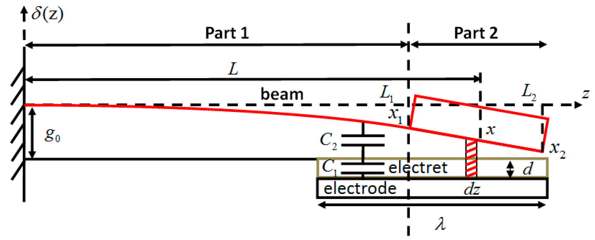
Because of the mass, the behavior of the beam has to be studied in two parts. A drawing of double-ended fixed beam is presented in Figure 2b which shows the deformation as a function of the position on the double-ended fixed beam for a deflection induced by an external force F applied to the center of mass. The first part has an additional mass: whose deflection is uniform and given by . The second part does not have an additional mass: whose deformation symmetrical on both sides of the mass and the deformation of the position can be considered as a trial function in the form of a cosine as . Therefore, for a given static deflection on the center of the mass, the deformation of the double-ended fixed beam can be simply expressed as a function of the parameters in both parts:
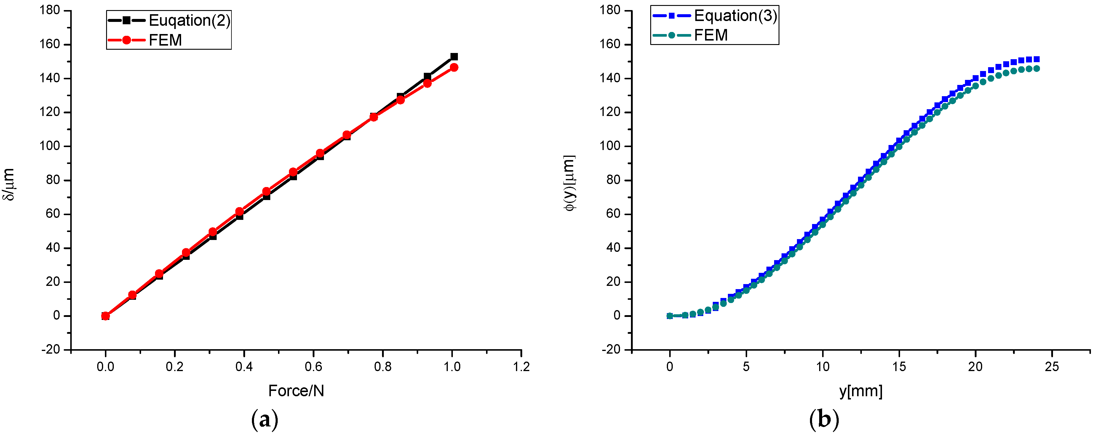
In order to verify the accuracy of the trial function in Equations (2) and (3), we compare the theoretical results with the simulation results. Figure 3 gives the deflection of the mass with an external force resulting from Equation (2) and deflection of the double-ended fixed beam with the position under a constant external force 1N resulting from Equation (3) compared with the deformations performed by FEM calculation (COMSOL Multiphysics). The double-ended fixed beam of L = 48 mm, w = 15 mm, h = 0.3 mm and l = 15 mm was fabricated of copper. The maximum error of deflection exits in Figure 3 is 4% at the center of mass. This proves that our deflection calculations using Equations (2) and (3) fit the FEM results.
Knowing the double-ended fixed beam deformation, the total capacitance can be divided into two parts. The first part can be considered as a parallel plate capacitor which can be obtained by . The second part can be considered a non-parallel capacitance, including infinite infinitesimal parallel length dy of the capacitor. One can get the infinitesimal capacitance for a given , . By integrating the expressions, the local total capacitance between both electrodes is:
The first term of Equation (4) represents the capacitance of the middle parallel part, the second term of Equation (4) represents the non-parallel capacitance formed by both sides of the support beam, where λ represents the length of the electret. The accuracy of the capacitance model in Equation (4) can be verified by means of the simulation software COMSOL and the curves are presented in Figure 4. The maximum error is 3.1% when the external force is an alternating load with an amplitude of 1N, = 0.4 mm and λ = 63 mm, so the results obtained by Equation (4) are in agreement with the FEM results. Deflection of mass is proportional to external force. The smaller the air gap between two electrodes, the higher the increase rate of the capacitance, as Figure 4 shows.
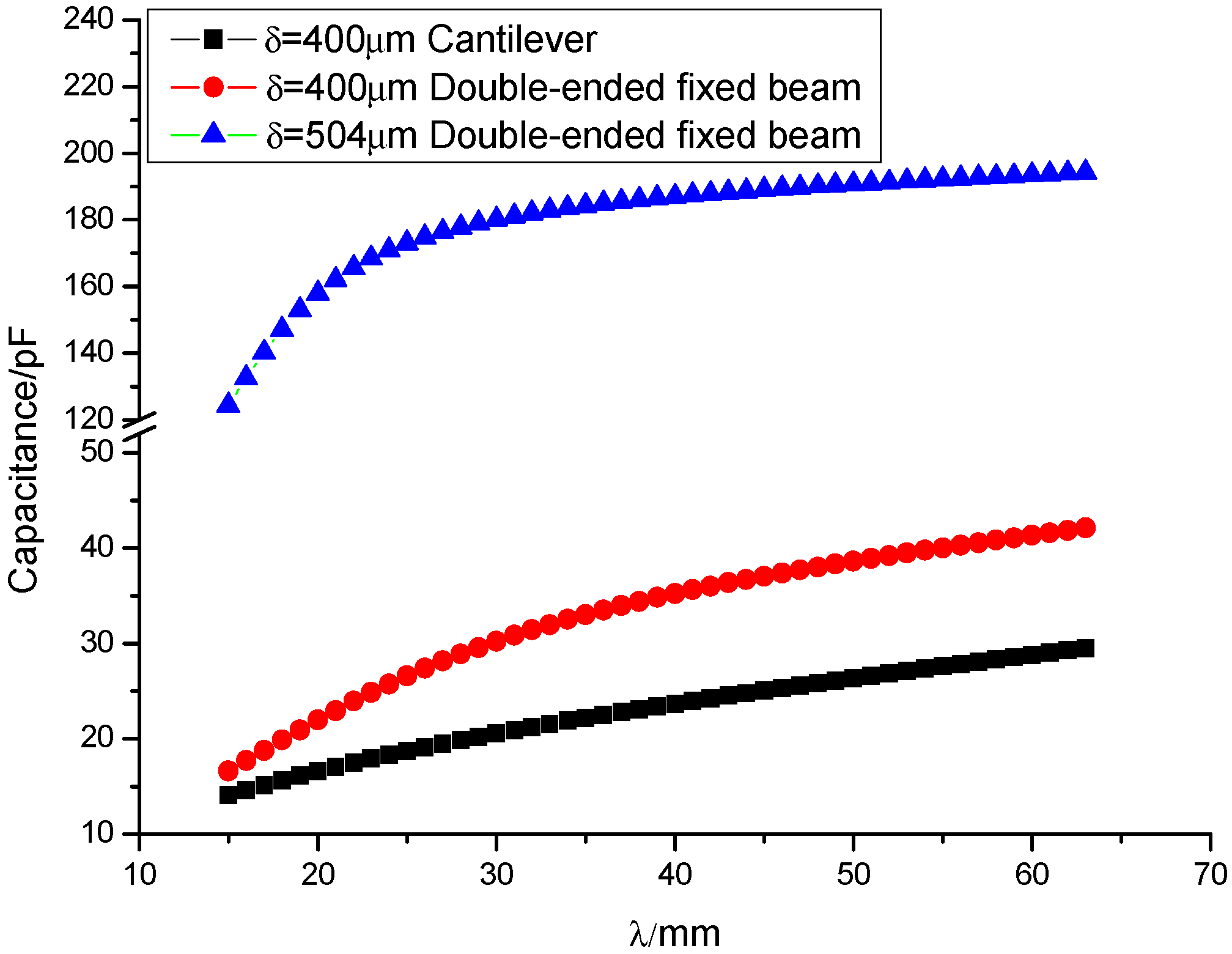
Now, a comparison can enable us to recognize the difference between the capacitance of double-ended fixed beam E-VEHs and cantilever E-VEHs, clearly. Figure 5 shows the capacitance between electrode and counter-electrode with different electret lengths (15 mm–63 mm) for double-ended fixed beam E-VEHs and cantilever E-VEHs, respectively, of initial air gap = 505 µm. The double-ended fixed beam has the same length, width and thickness as the single cantilever beam. The black circle dotted line denotes a cantilever based energy harvester’s change in capacitance value with electret length when the mass center under a deformation of x = 400 µm (at the moment, the tip deformation of the cantilever = 504 µm). The red triangle dotted line denotes a double-ended fixed beam E-VEHs’ change in capacitance value with electret length when the mass center is under a deformation of x = 400 µm. The blue square dotted line denotes a double-ended fixed beam E-VEHs’ change in capacitance value with electret length when the mass center under a deformation of x = 504 µm. In these three cases, the capacitance value increases with the length of the electret. The capacitance value of the cantilever beam is approximately linear with the length of the electret, the capacitance value reaches 14.6 pF when λ = 15 mm, and 29.5 pF when λ = 63 mm as Figure 5 shows. The capacitance value of the double-ended beam is approximately linear with the length of the electret also for = 400 µm, the capacitance value reaches 17.7 pF when λ = 15 mm, and 42.1 pF when λ = 63 mm as Figure 5 shows. In order to highlight the double-ended beam in the absence of contact between the electrode and counter-electrode can achieve a larger capacitance value, we added a curve when the deflection of mass of double-ended beam is equation to the deflection of the free end of cantilever. The capacitance value of the double-ended beam is significantly increased when = 504 µm. Before λ < 30 mm, so the capacitance value varies greatly with the length of the electret, when λ > 30 mm, the capacitance value varies slightly with the length of the electret, the capacitance value reaches 133 pF when λ = 15 mm, and 194 pF when λ = 63 mm, as Figure 5 shows. Compared with the cantilever, the double-ended fixed beam can significantly improve the capacitance value and capacitance change rate for the same size.
Capacitance versus external force of six different electret’ lengths are shown in Figure 6a, where the external force can be considered as a periodic force of 2N amplitude that starts from the trough to the crest. The capacitance reaches the minimum at the trough –2N which means the air gap reaches maximum at this time. The capacitance reaches the maximum at crest 2N, which means the air gap reaches minimum. The capacitance is proportional to the length of the electret, and, the longer electret length, the bigger capacitance variation in a period of external force as Figure 6b shows. The capacitance variation can reach 21 pF when the length of the electret is 63 mm, but the capacitance only reaches a 9.3 pF variation when the length of the electret is 15 mm.
The increasing rate of capacitance variation reduces with the increase of the length gradually until close to zero when the capacitance variation reaches a maximum, so finding an optimal length of the electret can not only save costs, but also improve the output power of E-VEHs.
3. External Vibration Energy Capture
3.1. Electrostatic Model
Electret-based vibration energy harvesters are electrostatic converters, and are therefore based on a capacitive structure made of two plates (electrode and counter-electrode) as seen in Figure 7a. The electret induces charges on the electrodes and counter-electrodes to respect Gauss’s law. Therefore, Qe denotes the charge on the electret is equal to the sum of Qb and Qt, where Qb is the total amount of charges on the electrode and Qt the total amount of charges on the counter-electrode (Qe = Qb + Qt). When the distance g between the electrode and the counter-electrode is changed due to an external excitation acted on the mass, the induced charge on the electrode and counter-electrode will redistribute as Figure 7b shows. The equivalent electrostatic model of the electrostatic converter is presented in Figure 7c, where, Vs is the surface voltage of electret and C(t) given in Equation (4) is the capacitance between the counter-electrode and the electrode. C(t) corresponds to the serial capacitance formed by the constant capacitance C2 of the electret dielectric material and the variable capacitance C1(t) of the air gap. Kirchhoff’s law gives the differential equation that governs the electrostatic system:
The surface potential Vs could be considered as a monotonous linear function of the initial charges Qe of electret, Vs = Qe/C2.
3.2. Mechanical-Electrostatic Coupling Model
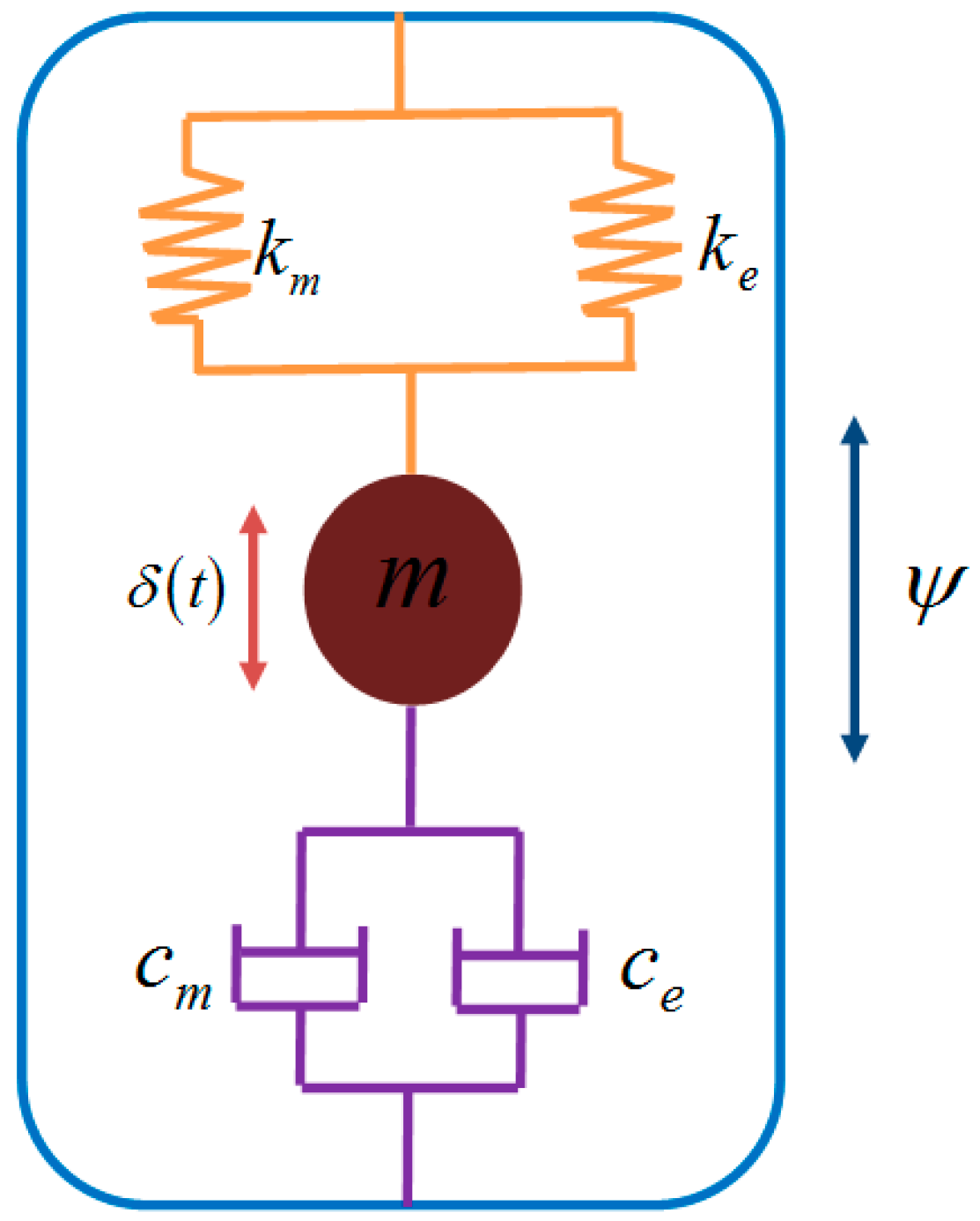
In order to capture energy from the external environment, the electrostatic systems have to be coupled with a mechanical vibration system as Figure 8 shows. The coupling factor of the system is determined by the electrostatic Felec between the electret and counter-electrode. Felec is the derivative of the electrostatic energy of the capacitor We with respect to the displacement . We is equal to the charge on the upper electrode Qt squared, divided by twice the capacitance as a function of time C(t). The system of equations that accounts for the energy harvester can be modeled as:
Output power Pout in experiment can be calculated from a time-average as Equation (7) shows,
where T represents the measuring time period, R means the load resistance, and Vout is the output voltage across the resistive load. Nevertheless, it is hard to solve Equation (7) by analytic methods.
In general, the surface potential Vs, the load resistance Rand the bias capacitance value (mainly determined by initial air gap and electret length λ) play important roles in the performances of out-of-plane E-VEHs when the other parameters are considered as constant.
In this paper, we mainly study the dependence of output power, resonance frequency and frequency band width on the electret length λ for double-ended fixed beam out-of-plane E-VEHs. The parameters of the fixed parameters of double-ended fixed beam out-of-plane E-VEHs are listed in Table 1.
4. Numerical Study
It is hard to obtain the analytical result of Equation (6) due to the nonlinear nature of electrostatic force between the electrode and counter-electrode. A simulation model based on Equation (6) can enable us study the performances of E-VEHs with the help of Matlab/Simulink (MathWorks, Natick, MA, USA).
The voltage of load resistance versus frequency for three external acceleration amplitudes is shown in Figure 9, where the external acceleration not only increases the output power but also reduces the resonance frequency. To use an out-of-plane double-ended fixed beam E-VEHs as a tool to harvest energy from the external environment, it should be best to have a bigger acceleration before impact to capture more energy, so we set the external acceleration amplitude at 5 m/s2 in this study to ensure high output power and to avoid impacts.
Plots of output power versus electret lengths are shown in Figure 10, and are different from the static conditions as Figure 6 shows, because there exists an optimal value of electret length λ = 33 mm to reach the maximum power 0.75 mW because of the coupling effect between the electrostatic unit and mechanical vibration unit when the other parameters are determined. Asanuma [20] reported that the time-average output power is proportional to the capacitance variation , the vibration frequency f and the square of the electret surface potential Vs:
The resonance frequency continues to decrease as the electret length increases, whereas becomes saturated. The saturation of results from the decrease in the displacement of the oscillator by the enhanced electrostatic force. Thus, as deduced from Equation (8), the decrease in output power by further increasing the electret length beyond the optimal value is mainly attributed to the decreased resonance frequency. It is well known that there also exists an optimal load resistance for E-VEHs to reach the maximum output power. The high optimal load resistance is a major problem for E-VEHs in practical utilization. The optimal load resistance is 60 MΩ when the electret length is 10 mm, but when the electret length increases to 60 mm, the optimal load resistance reduces to 15 MΩ, so increasing the electret length to reduce the optimal load resistance is a feasible solution for E-VEHs in practical utilization.
Electret lengths not only changes E-VEHs output power but also affect its resonance frequency and bandwidth as Figure 11 shows. The resonance frequency decreases as the electret length increases. The maximum frequency drift can reach 1 Hz when the electret length λ = 60 mm. Generally, the half power bandwidth of the vibration energy harvester is only several Hz, and a resonance frequency shift of 0.1 Hz will reduce the output power remarkably. Then electret lengths can be used to match the resonance frequency within a certain range. Furthermore, the lower load resistance, the bigger frequency variations as Figure 11a shows. The frequency bandwidth increases as electret length increases. The maximum bandwidth reaches 1.8 Hz when the electret length λ = 60 mm. Wideband width is a primary demand for E-VEHs in practical application. Then electret lengths can be used to broaden the bandwidth.
5. Experimental Study
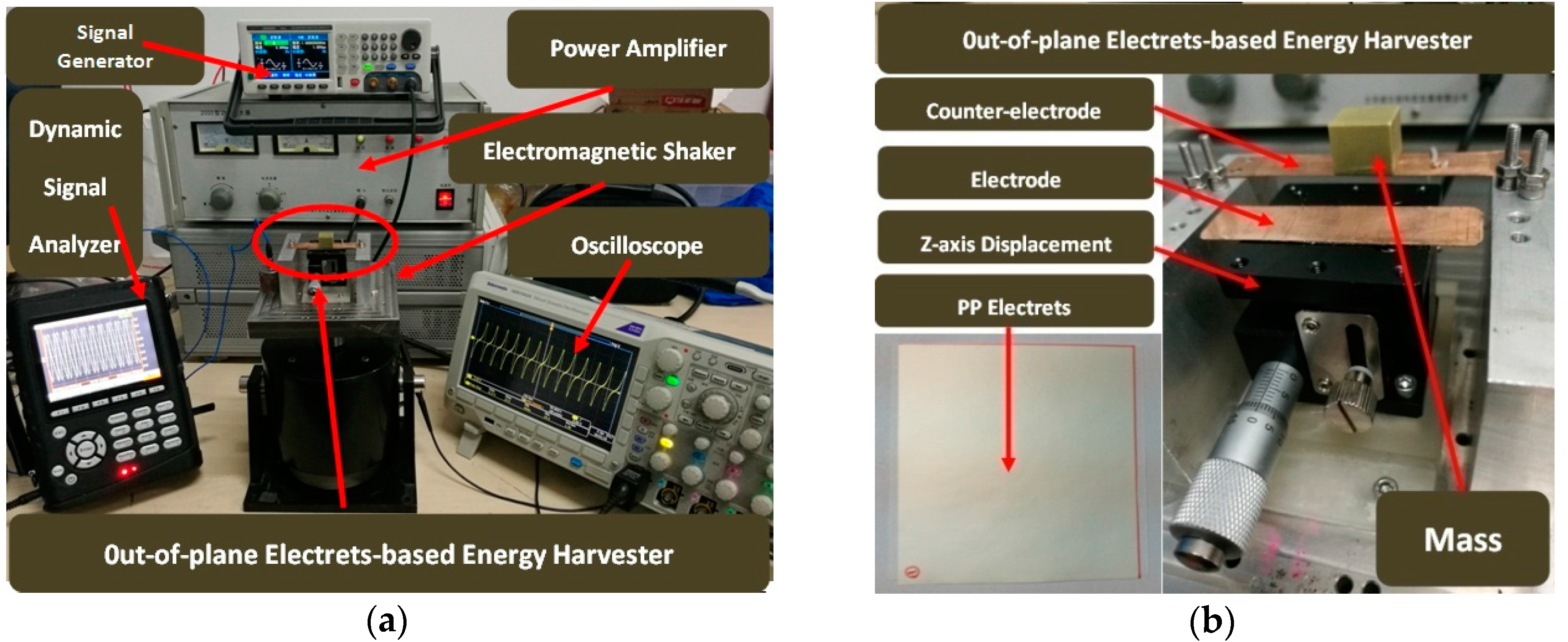
In this study, a prototype of a double-ended fixed beam E-VEH was fabricated in order to verify our predictions. We employed a 30 µm thick copper sheet to fabricate a double-ended fixed beam oscillator. A 15 mm × 15 mm × 10 mm ceramic mass was added at the middle of the beam to increase the output power. A PP polymer electret film with –480 V surface potential (Shanghai Electret Materials Technology Co. Ltd., Shanghai, China) was prepared using the point-to-grid corona-discharge method. The charged PP polymer electret film was spin-coated on a rigid copper plate with the help of a copper double-tape. A copper foil was pasted in the lower surface of double-ended fixed beam through the adhesive as a counter-electrode. As shown in Figure 12, the harvester was assembled and set on the shaker. A Z-axial displacement platform with 10 µm accuracy was used to control the initial air gap between the electrode and counter-electrode precisely. A high speed photographer was used to measure the peak-to-peak amplitude of the centre of the oscillator. An oscilloscope with 10 MΩ input impedance and 3.3 pF parasitic capacitance was used to measure the output voltage of the harvester. The schematic of measuring output voltage was showed in Figure 13.
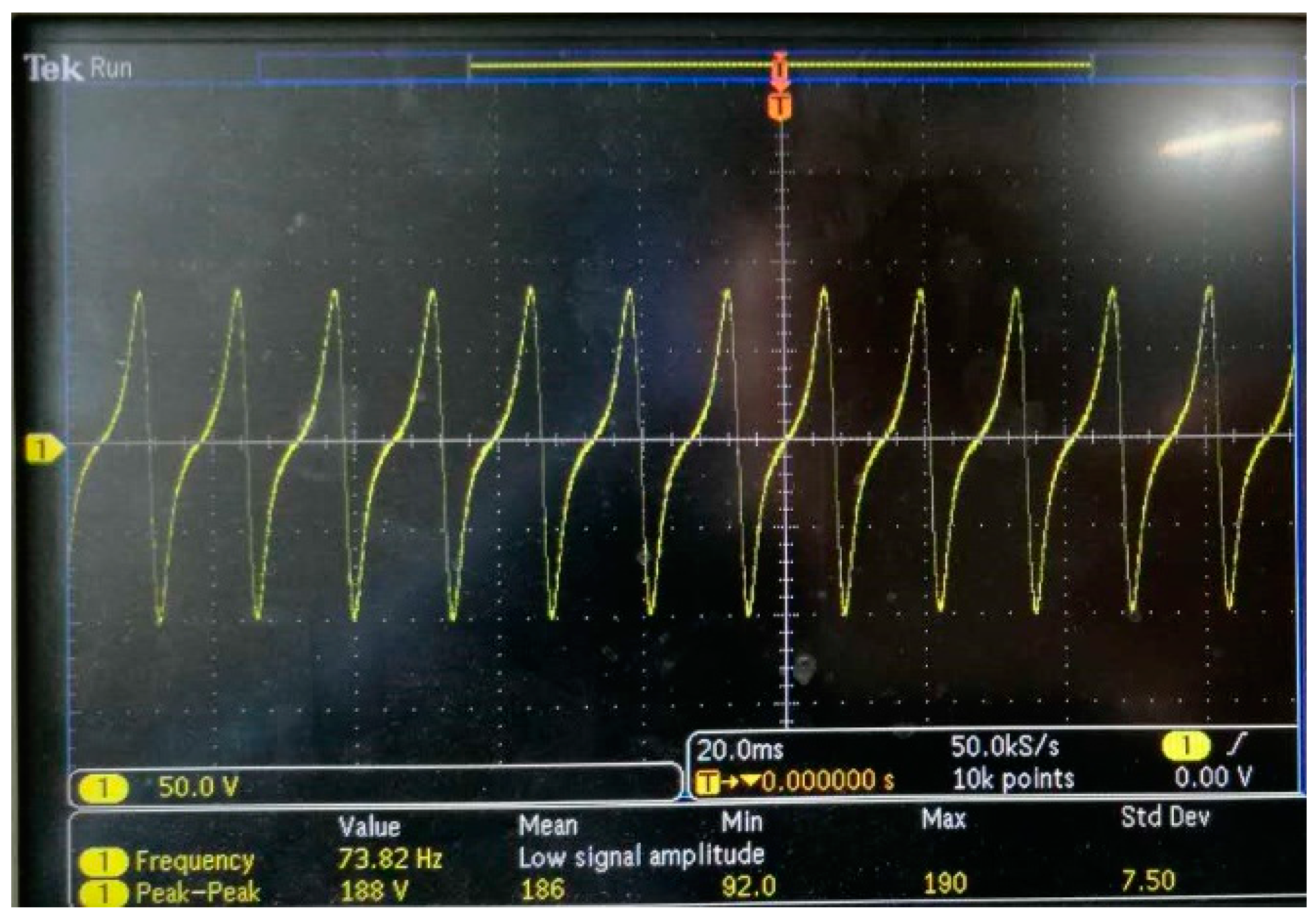
Measurements of the output voltage generated by the E-VEHs are shown in Figure 14. The peak-peak voltage of a 10 MΩ load resistance can reach 186 V with a 0.6 g external acceleration at a frequency of 73.8 Hz. It is too high to support a wireless sensor network which only required a 3 V voltage before rectification by a diode bridge-capacitor circuit or a power management device, for example an LM3588. The output voltage of double-ended fixed beam electret harvester has a characteristic as Figure 14 shows: there exists a discontinuity when the voltage gets through its maximum value to its minimum value. This peculiarity is due to the fact that the current which flows through the load resistance changes its direction when the variation capacitance passes its maximum. The current will change its direction again when the variation capacitance passes its minimum, but no discontinuity appears then because the current equals zero at this moment.
Results when the load resistance is maintained at 10 MΩ and sweeping frequencies up and down for three different acceleration amplitudes are shown in Figure 15. There is no obvious hysteresis between the up-sweep and down-sweep as the acceleration amplitude was increased from 3 m/s2 to 5 m/s2, which indicates that it is reasonable to ignore the hard spring effect of the double-ended fixed beam in the previous model. The electrostatic force increases as the acceleration amplitude increases as can be shown by the decreased resonance frequency. The resonance frequency of 3 m/s2 is 74.1 Hz, and 73.3 Hz for 5 m/s2. The differences between the experimental resonance frequency results and the numerical simulation results are caused by the fact that preloading of the nuts changes the resonant frequency of the mechanical vibration system. The output voltages obtained by the experimental test are lower than the simulated voltages of all three different acceleration amplitudes due to the parasitic capacitance.
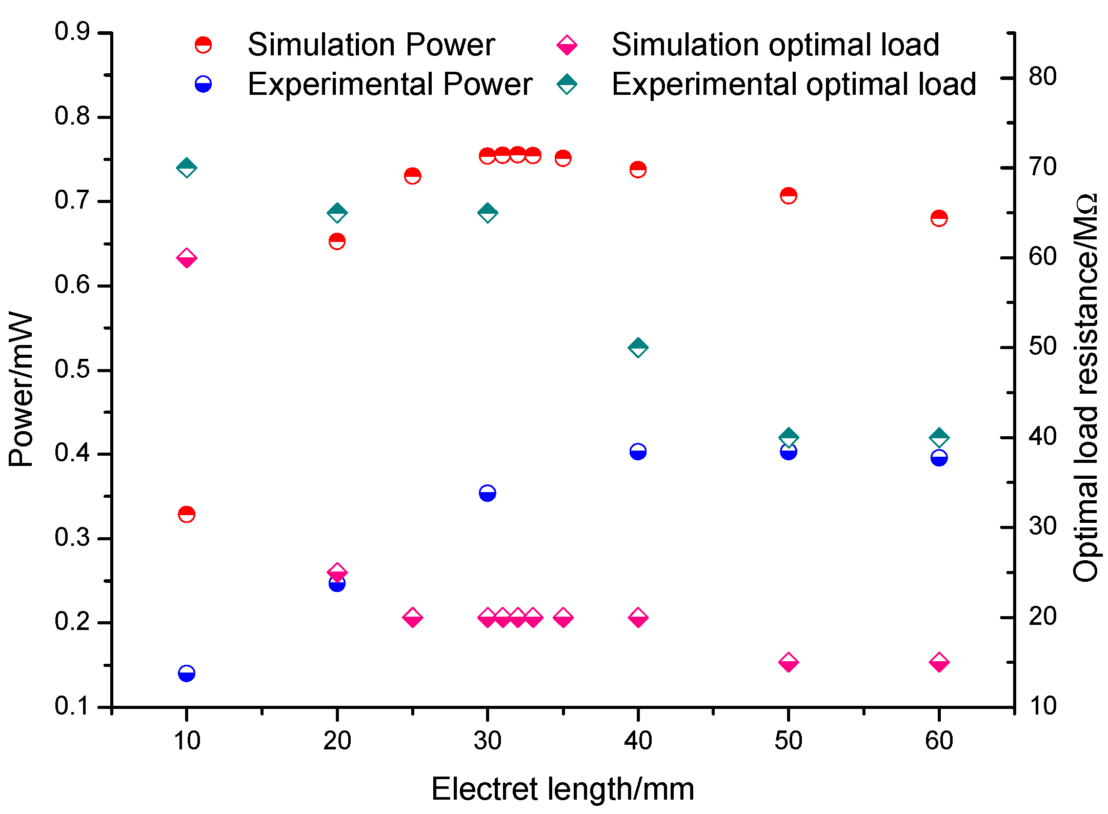
We keep the acceleration amplitude at 5 m/s2 and investigate the dependence of electret length on output power, resonance frequency and bandwidth for double-ended fixed beam E-EVHs. In general, several relatively important parameters such as initial air gap, load resistance and electret length are not independent. Further, there exists an optimal load resistance to reach the maximum output power if the other parameters have been set. Different electret lengths corresponding to different optimal load resistances were obtained when the initial air gap was keep constant. Six different lengths of electret such as 60, 50, 40, 30, 20 and 10 mm are investigated in this paper, both at their optimal load resistances and 10 MΩ, respectively.
Figure 16 shows the output power and optimal load resistance versus electret length when the external acceleration amplitude was kept at 5 m/s2. As we predicted in the simulation analysis, there exists an optimal electret length value of λ = 40 mm to reach the maximum power 0.404 mW and optimal load resistance decreases as the electret increases. Further, when the length of the electret was increased to 60 mm, the output power decreased to 0.396 mW. The maximum output power increases by 188% when the electret length increases from 10 mm to 40 mm. In fact, when the electret length is greater than 40 mm, the output power attenuation is not as obvious as in the simulation, which is probably due to fact the resonant frequency drift is not significant.
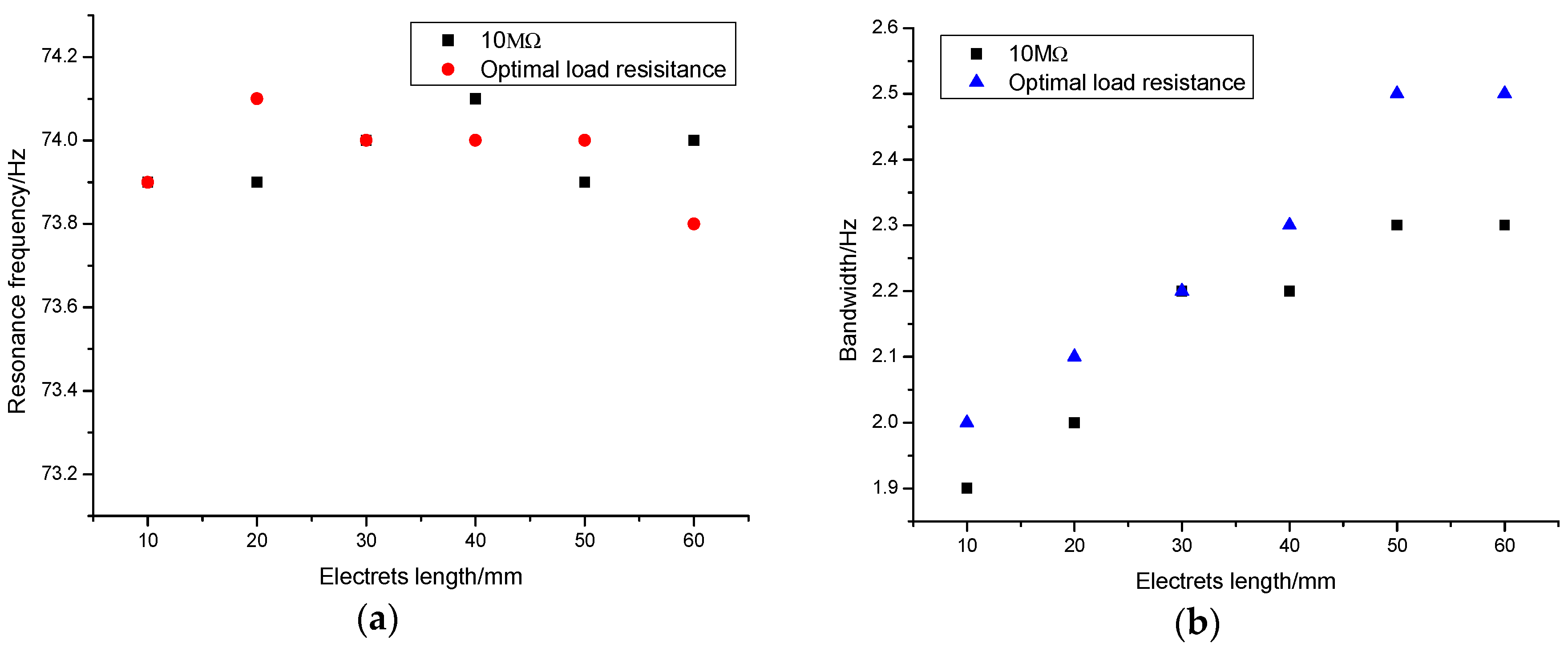
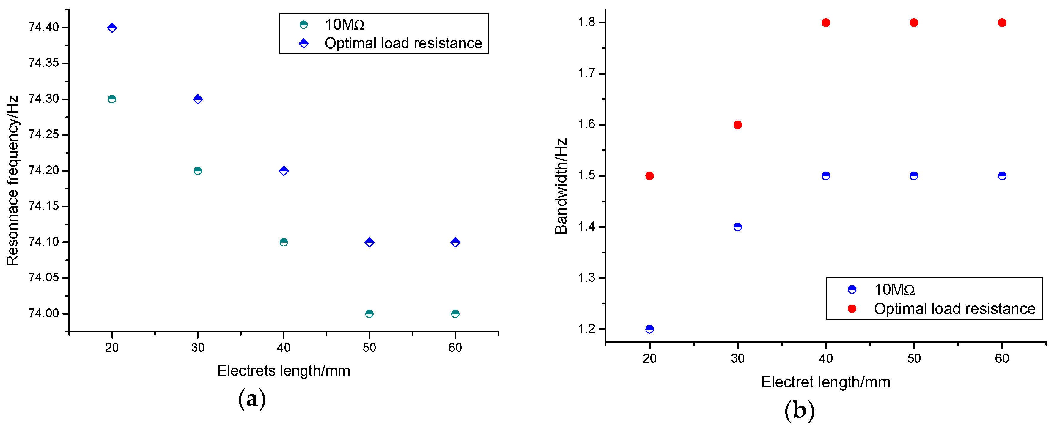
There is no obvious law of resonance frequency in our experiments for different electret lengths as Figure 17a shows. This is caused by the inevitable error in our experiment because when we change the length of the electret we need to re-tighten the nut which will change the resonance frequency of the double-ended fixed beam-mass system more or less. The maximum variation of resonance frequency in previous simulation is 0.3 Hz, so we think the resonance frequency drift in our experiment caused by different electret length can be ignored. Half power versus bandwidth of output increases as electret increase can be clearly expressed in Figure 17b. The bandwidth increases by 25% when the electret length increases from 10 mm to 60 mm.
While similar overall trends were seen, there exist large discrepancies between the absolute output power values of the numerical and experimental results. The difference of output power may be due to the following factors: First, surface potential decay of the PP electret; Because E-VEHs’ output power is positively related to the square of the surface potential, a slight potential decay of PP electret’ surface potential will greatly reduce the output power. Second, a parasitic capacitance built into the experiment step, especially when using high-value resistors; the maximum capacitance variation of our E-VEHs type remains at only decade pF. Thus, a parasitic capacitance, even with only decade pF, will significantly decrease the relative capacitance variation and thus the output power. Third, the energy dissipation due to damping is larger in the experiment than in the simulation as can be seen from the bandwidth. Despite the large differences between the absolute values of output power for the numerical and experimental results, it but does not affect the main conclusions in this paper and our research also reaches the current level as Table 2 shows.
6. Conclusions
In this paper we have developed a capacitance theoretical model of a double-ended fixed beam E-VEH which was verified to have high accuracy by FEM (COMSOL Multiphysics). Compared with cantilever E-VEHs, double-ended fixed beam E-VEHs have higher capacitance and bigger capacitance variation under the same conditions. The analytical and simulation results show that both capacitances and capacitance variations increase as electret length increases when one takes no account of electromechanical coupling.
We studied the characteristics of double-ended fixed beam out-of-plane E-EVHs for different electret lengths through simulation and experiment methods, respectively. A simulation model based the analytical model presented in this paper was built. The simulation results show that there exists an optimal electret length to reach the maximum power for double-ended fixed beam out-of-plane E-EVHs when the other parameters are kept constant. Enhanced electrostatic forces with increasing the electret length emphasizes the soft spring effect, which widens the half power bandwidth and lowers the resonance frequency. Increasing electret length also decreases the optimal load resistance of E-EVHs. A small double-ended fixed beam out-of-plane E-EVHs was fabricated, and the experimental results were qualitatively consistent with the simulation results. Despite the presence of parasitic capacitance interference and surface potential decay of the electret, the maximum power harvester in our experimental device can reach 0.404 mW and exceed most recent state-of-the-art out-of-plane E-EVHs. The maximum bandwidth reached is 2.5 Hz at the electret length of 60 mm. Therefore, the electret length should be set between 40 mm and 60 mm, to ensure a higher output power and also get a larger bandwidth in practical applications.
Acknowledgments
This project is supported by the National High Technology Research and Development Program of China (grant No. 2013AA041104).
Author Contributions
Chunhui Gao conceived of the work, analyzed the theory, designed the structure, carried out the experiments and wrote the paper. Shiqiao Gao provided supervision and guidance in the theory study. Lei Jin and Junhu Lu helped Chunhui Gao improve the quality of the work. Haipeng Liu commented on the work.
Conflicts of Interest
The authors declare no conflict of interest.
References
- Ling, C.S.; Dan, H.; Steve, G.B. Technological challenges of developing wireless health and us a GE monitoring systems. Proc. SPIE 2013. [Google Scholar] [CrossRef]
- Karami, M.A.; Inman, D.J. Powering pacemakers from heart beat vibrations using linear and nonlinear energy harvesters. Appl. Phys. Lett. 2012, 100, 042901. [Google Scholar] [CrossRef]
- Roseveare, N.; Natarajan, B. A structured approach to optimization of energy harvesting wireless sensor networks. In Proceedings of the IEEE Conference on Consumer Communications and Networking, Las Vegas, NV, USA, 11–14 January 2013; pp. 420–425. [Google Scholar]
- Harne, R.L.; Wang, K.W. A review of the recent research on vibration energy harvesting via bistable systems. Smart Mater. Struct. 2013, 22, 023001. [Google Scholar] [CrossRef]
- Mitcheson, P.D.; Green, T.C.; Yeatman, E.M. Power processing circuits for electromagnetic, electrostatic and piezoelectric inertial energy scavengers. Microsyst. Technol. 2007, 13, 1629–1635. [Google Scholar] [CrossRef] [Green Version]
- Li, P.; Gao, S.; Niu, S.; Liu, H.; Cai, H. An analysis of the coupling effect for a hybrid piezoelectric and electromagnetic energy harvester. Smart Mater. Struct. 2014, 23, 065016. [Google Scholar] [CrossRef]
- Crovetto, A.; Wang, F.; Hansen, O. Modeling and optimization of an electrostatic energy harvesting device. J. Microelectromech. Syst. 2014, 23, 1141–1155. [Google Scholar] [CrossRef] [Green Version]
- Paracha, A.; Basset, P.; Galayko, D.; Marty, F.; Bourouina, T. A silicon MEMS DC/DC converter for autonomous vibration-to-electrical-energy scavenger. IEEE Electron. Device Lett. 2009, 30, 481–483. [Google Scholar] [CrossRef]
- Sakane, Y.; Suzuki, Y.; Kasagi, N. The development of a high-performance perfluorinated polymer electret and its application tomicro power generation. J. Micromech. Microeng. 2008, 18, 104011. [Google Scholar] [CrossRef]
- Sterken, T.; Fiorini, P.; Altena, G.; van Hoof, C.; Puers, R. Harvesting energy from vibrations by a micromachined electret generator. In Proceedings of the International Conference of Solid-State Sensors, Actuators and Microsystems, Lyon, France, 10–14 June 2007; pp. 129–132. [Google Scholar]
- Wen Lo, H.; Tai, Y.-C. Parylene-based electret power generators. J. Micromech. Microeng. 2008, 18, 104006. [Google Scholar]
- Naruse, Y.; Matsubara, N.; Mabuchi, K.; Izumi, M.; Suzuki, S. Electrostatic micro power generation from low-frequency vibration such as human motion. J. Micromech. Microeng. 2009, 19, 094002. [Google Scholar] [CrossRef]
- Crovetto, A.; Wang, F.; Hansen, O. An electret-based energy harvesting device with a wafer-level fabrication process. J. Micromech. Microeng. 2013, 23, 114010. [Google Scholar] [CrossRef]
- Wang, F.; Hansen, O. Invisible surface charge pattern on inorganic electrets. IEEE Electron. Device Lett. 2013, 34, 1047–1049. [Google Scholar] [CrossRef]
- Miki, D.; Honzumi, M.; Suzuki, Y.; Kasagi, N. Large-amplitude MEMS electret generator with nonlinear spring. In Proceedings of the IEEE 23rd International Conference on Micro Electro Mechanical Systems (Wanchai), Hong Kong, China, 24–28 January 2010; pp. 176–179. [Google Scholar]
- Renaud, M.; Altena, G.; Goedbloed, M.; de Nooijer, C.; Matova, S.; Naito, Y.; von Schaijk, R. A high performance electrostatic MEMS vibration energy harvester with corrugated inorganic SiO2-Si3N4 electret. In Proceedings of the 17th International Conference on Solid-State Sensors, Actuators and Microsystems, Barcelona, Spain, 16–20 June 2013; pp. 693–696. [Google Scholar]
- Boisseau, S.; Despesse, G.; Ricart, T.; Defay, E.; Sylvestre, A. Cantilever-based electret energy harvesters. Smart Mater. Struct. 2011, 20, 105013. [Google Scholar] [CrossRef]
- Chiu, Y.; Lee, Y.C. Flat and robust out-of-plane vibrational electret energy harvester. J. Micromech. Microeng. 2012, 23, 015012. [Google Scholar] [CrossRef]
- Asanuma, H.; Oguchi, H.; Hara, M.; Yoshida, R.; Kuwano, H. Ferroelectric dipole electrets for output power enhancement in electrostatic vibration energy harvesters. Appl. Phys. Lett. 2013, 103, 162901. [Google Scholar] [CrossRef]
- Asanuma, H.; Hara, M.; Oguchi, H.; Kuwano, H. Air gap optimization for output power and band width in out-of-plane vibration energy harvesters employing electret. J. Micromech. Microeng. 2015, 25, 104013. [Google Scholar] [CrossRef]
- Gao, C.; Gao, S.; Liu, H.; Jin, L.; Lu, J.; Li, P. Optimization for output power and band width in out-of-plane vibration energy harvesters employing electrets theoretically, numerically and experimentally. Microsyst. Technol. 2017. [Google Scholar] [CrossRef]
- Hajati, A. Ultra Wide-Bandwidth Micro Energy Harvester. Ph.D. Thesis, Massachusetts Institute of Technology, Cambridge, MA, USA, February 2011. [Google Scholar]
- Lu, Y.; O’Riordan, E.; Cottone, F.; Boisseau, S.; Galayko, D.; Blokhina, E.; Marty, F.; Basset, P. A batch-fabricated electret-biased wideband MEMS vibration energy harvester with frequency-up conversion behavior powering a UHF wireless sensor node. J. Micromech. Microeng. 2016, 26, 124004. [Google Scholar] [CrossRef]
- Zhang, Y.; Luo, A.; Xu, Y.; Wang, T.; Zhang, A.; Wang, F. Electret-based electrostatic energy harvesting device with the MEMS technology. In Proceedings of the 2016 12th IEEE/ASME International Conference on Mechatronic and Embedded Systems and Applications (MESA), Auckland, New Zealand, 29–31 August 2016; pp. 1–6. [Google Scholar]
Figure 1.
Deformation of the cantilever for an imposed deflection x [17].
Figure 1.
Deformation of the cantilever for an imposed deflection x [17].

Figure 2.
(a) Double-ended fixed beam out-of-plane E-VEHs; (b) Deformation of the double-ended fixed beam for an imposed deflection
Figure 2.
(a) Double-ended fixed beam out-of-plane E-VEHs; (b) Deformation of the double-ended fixed beam for an imposed deflection
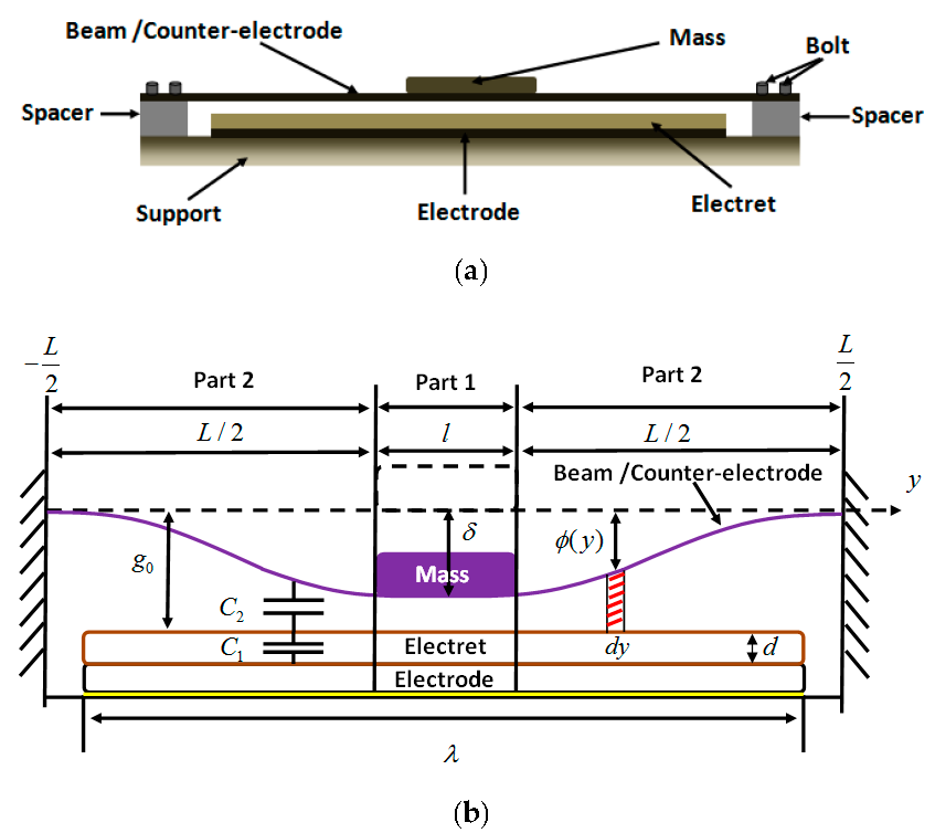
Figure 3.
(a) Deflection of the mass with external force; (b) Deflection of the double-ended fixed beam with the position y under a constant external force 1N.
Figure 3.
(a) Deflection of the mass with external force; (b) Deflection of the double-ended fixed beam with the position y under a constant external force 1N.

Figure 4.
Capacitance between electrode and counter-electrode with external force.
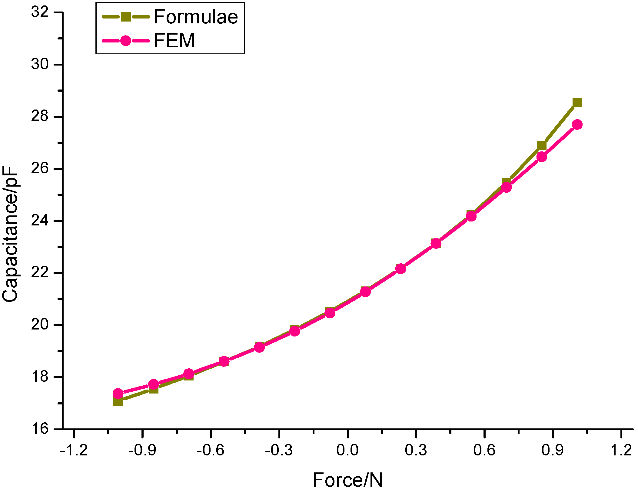
Figure 5.
Capacitance between electrode and counter-electrode with different electret lengths of cantilever and double-ended fixed beam respectively.
Figure 5.
Capacitance between electrode and counter-electrode with different electret lengths of cantilever and double-ended fixed beam respectively.

Figure 6.
(a) Capacitance versus external force; (b) Capacitance variations with electret length.
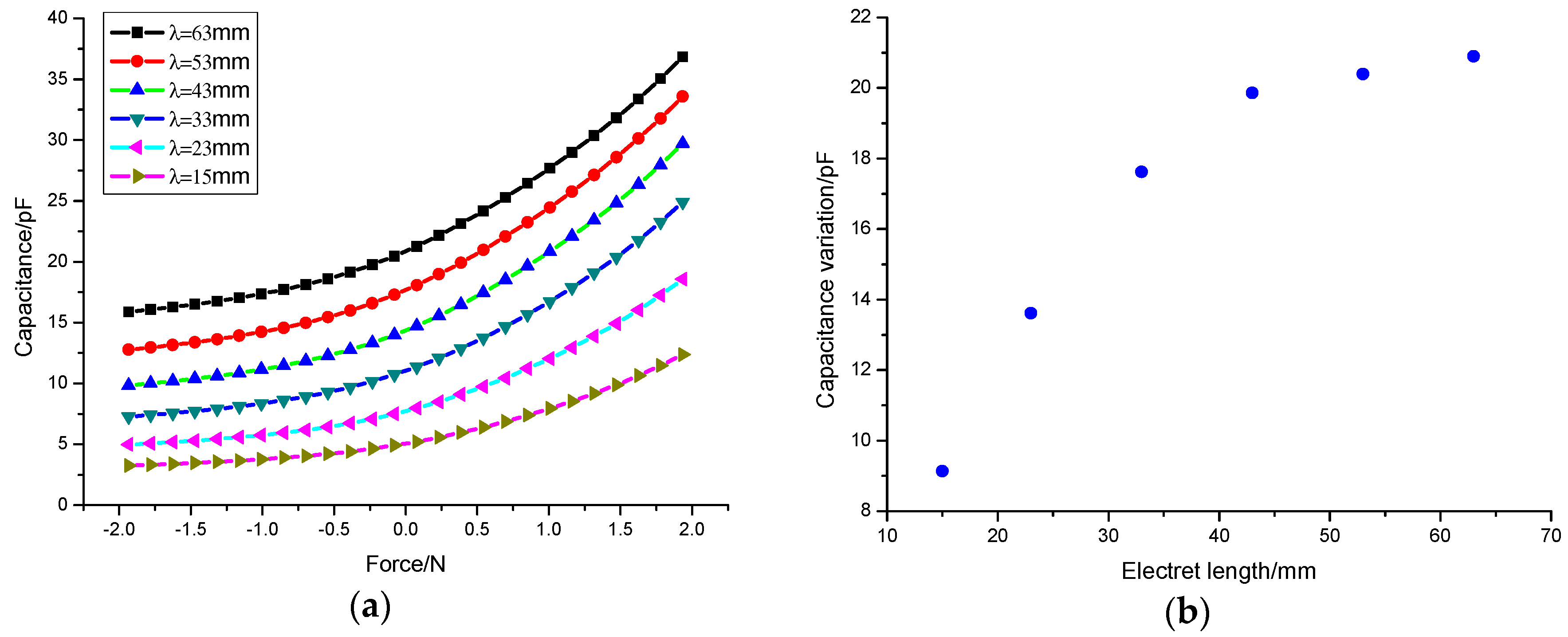
Figure 7.
(a) Electrostatic converter using electret; (b) Charge circulation; (c) Equivalent circuit model.
Figure 7.
(a) Electrostatic converter using electret; (b) Charge circulation; (c) Equivalent circuit model.
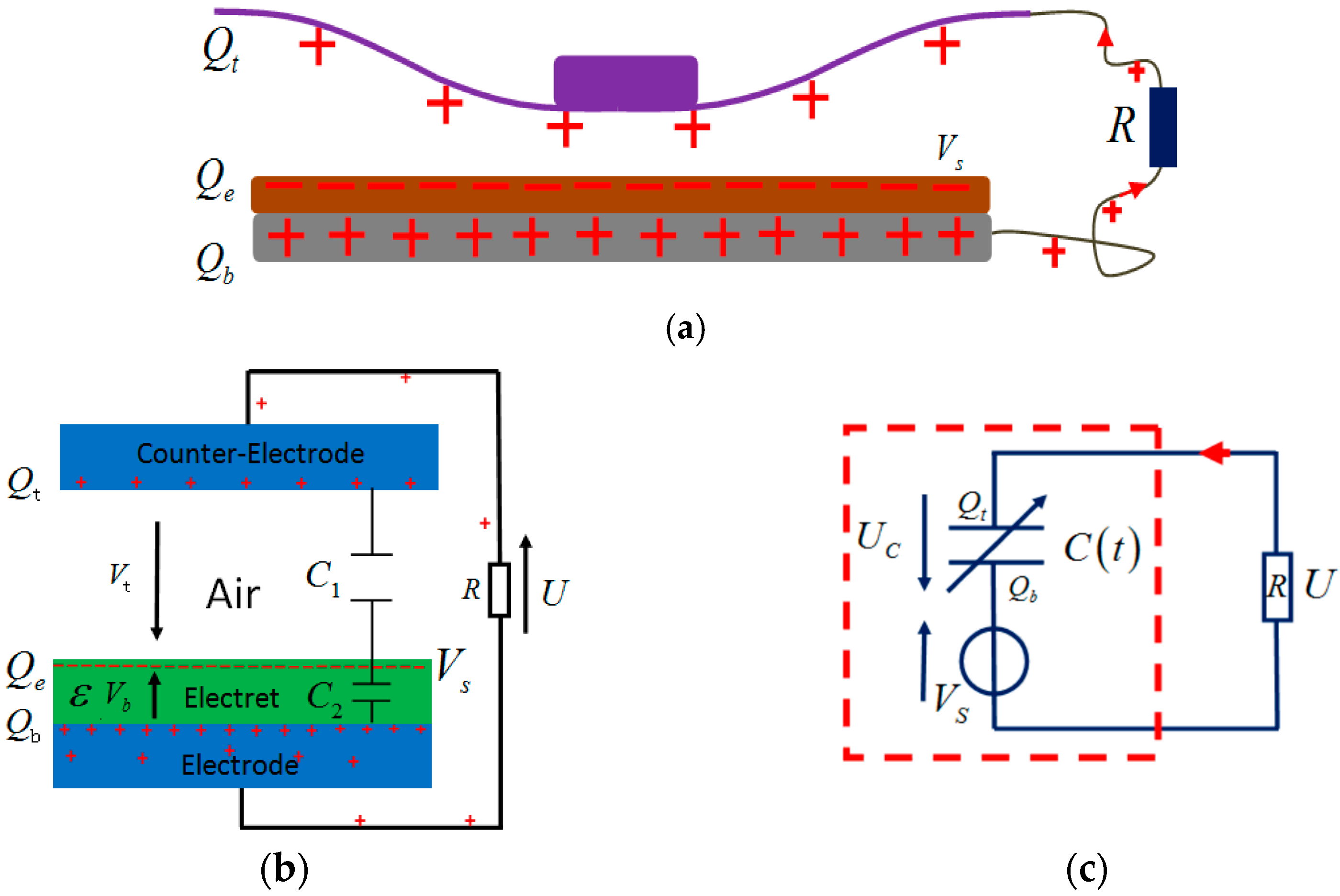
Figure 8.
Kinetic model of E-EVHs.

Figure 9.
Voltage versus to frequency for three external acceleration amplitudes.
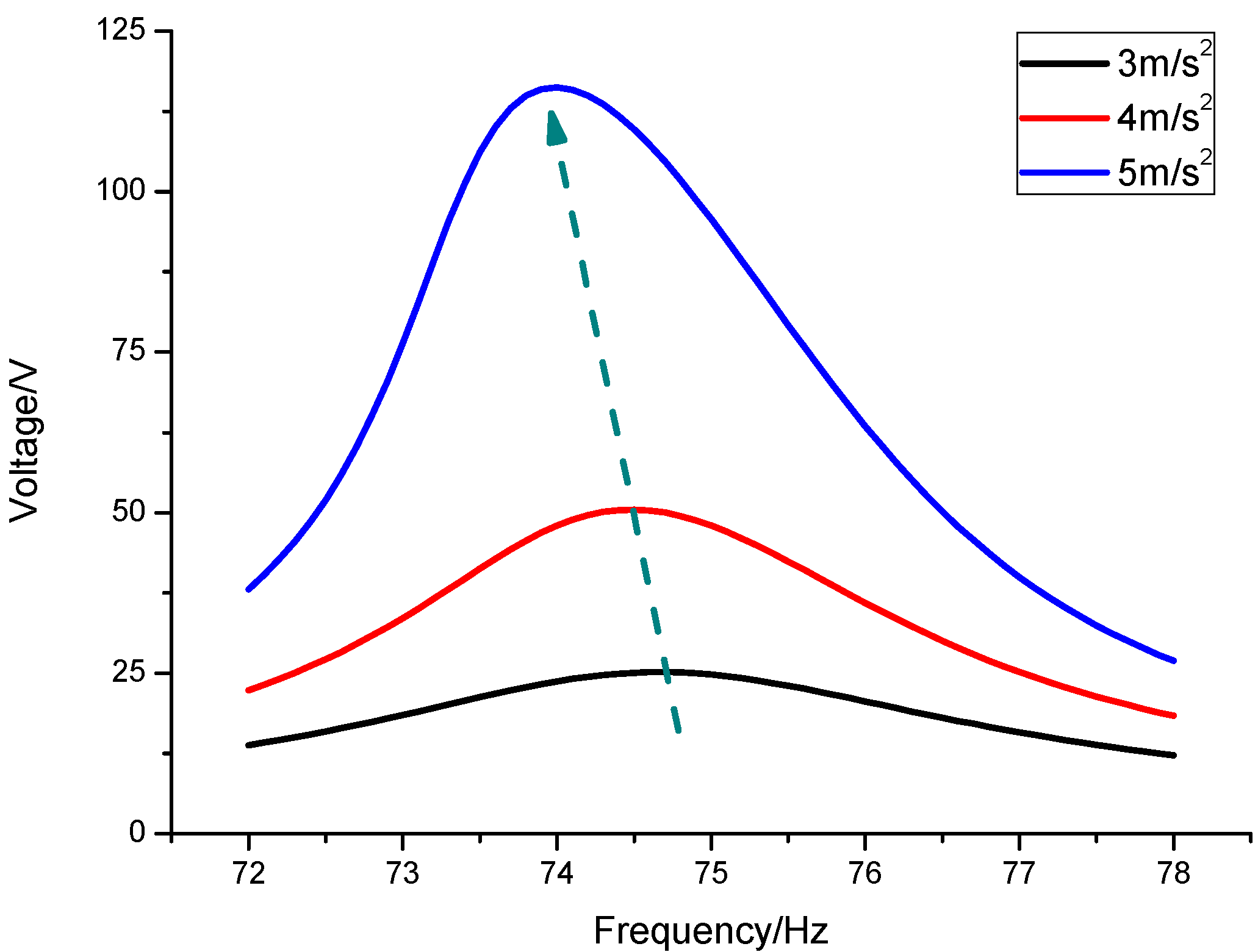
Figure 10.
Output power and optimal load resistance versus electret length.

Figure 11.
(a) Resonance frequency and (b) half power bandwidth versus electret length.

Figure 12.
A prototype of double-ended fixed beam E-VEHs (a) Exploded view; (b) Assembled view.

Figure 13.
Schematic for measuring the output voltage.
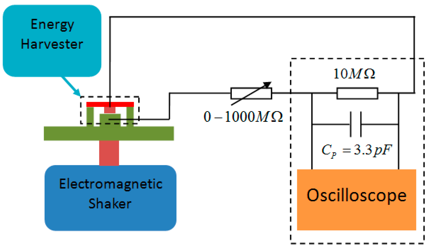
Figure 14.
Peak-peak voltage of load resistance.

Figure 15.
Up and down-sweep for different acceleration amplitude.
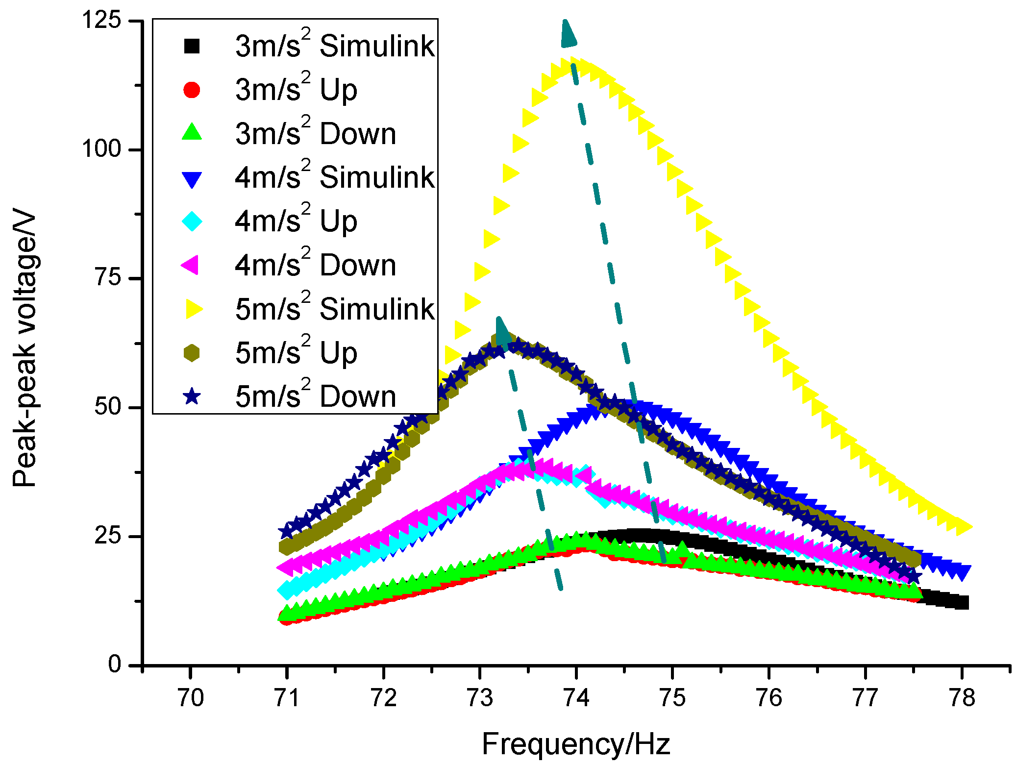
Figure 16.
Output power and optimal load resistance versus electret length.

Figure 17.
(a) Resonance frequency and (b) Half power versus electret length.

Table 1.
Fixed parameters of double-ended fixed beam out-of-plane E-VEHs.
| Parameters | Designation | Value |
|---|---|---|
| Angular frequency ofvibration | 75 Hz | |
| Melectret | Material of the electret | PP |
| m | Mobile mass | 17.8 g |
| Vs | PP surface potential | –480 V |
| Dielectric constant of the electret | 2.2 | |
| d | Electret thickness | 30 µm |
| Initial air gaps | 400 µm | |
| L | The length of the beam | 48 mm |
| l | The length of the mass | 15 mm |
| w | The width of the beam | 15 mm |
Table 2.
Comparison with seven prototypes among the most recent state-of-the-art electret-based energy harvesters.
Table 2.
Comparison with seven prototypes among the most recent state-of-the-art electret-based energy harvesters.
| Author | Surface Potential | Power | Electret Area | Acceleration | Density |
|---|---|---|---|---|---|
| Boisseau [17] | –1400 V | 50 µW | 4.16 cm2 | 0.1 g | 120.19 µW/cm2/g |
| Yi [18] | –400 V | 2.07 µW | 1 cm2 | 2 g | 10.3 µW/cm2/g |
| Asanuma [20] | –420 V | 4 µW | 1 cm2 | 0.5 g | 1.6 µW/cm2/g |
| Lu [23] | –45 V | 6.6 µW | 0.748 cm2 | 2 g | 4.4 µW/cm2/g |
| Zhang [24] | –400 V | 2.2 µW | 0.9 cm2 | 1 g | 2.44 µW/cm2/g |
| This paper | –480 V | 404 µW | 6 cm2 | 0.5 g | 134.66 µW/cm2/g |
© 2017 by the authors. Licensee MDPI, Basel, Switzerland. This article is an open access article distributed under the terms and conditions of the Creative Commons Attribution (CC BY) license (http://creativecommons.org/licenses/by/4.0/).
Share and Cite
MDPI and ACS Style
Gao, C.; Gao, S.; Liu, H.; Jin, L.; Lu, J. Electret Length Optimization of Output Power for Double-End Fixed Beam Out-of-Plane Electret-Based Vibration Energy Harvesters. Energies 2017, 10, 1122. https://doi.org/10.3390/en10081122
AMA Style
Gao C, Gao S, Liu H, Jin L, Lu J. Electret Length Optimization of Output Power for Double-End Fixed Beam Out-of-Plane Electret-Based Vibration Energy Harvesters. Energies. 2017; 10(8):1122. https://doi.org/10.3390/en10081122
Chicago/Turabian StyleGao, Chunhui, Shiqiao Gao, Haipeng Liu, Lei Jin, and Junhu Lu. 2017. "Electret Length Optimization of Output Power for Double-End Fixed Beam Out-of-Plane Electret-Based Vibration Energy Harvesters" Energies 10, no. 8: 1122. https://doi.org/10.3390/en10081122
Note that from the first issue of 2016, this journal uses article numbers instead of page numbers. See further details here.