Design and Construction of 1 MW Class Floating PV Generation Structural System Using FRP Members


1
Department of Architectural Engineering, Gachon University, Seongnam 13120, Korea
2
Department of Civil Engineering, Hongik University, Seoul 04066, Korea
*
Author to whom correspondence should be addressed.
Energies 2017, 10(8), 1142; https://doi.org/10.3390/en10081142
Submission received: 22 May 2017
/
Revised: 11 July 2017
/
Accepted: 1 August 2017
/
Published: 3 August 2017
(This article belongs to the Special Issue PV System Design and Performance)
Abstract
:The paper investigates overview of construction process of a 1 MW class floating photovoltaic (PV) generation structural system fabricated with fiber reinforced polymer (FRP) members. The floating PV generation system consists of unit structures linked by a hinge type connection of which the effect of bending moment between the unit structures, induced by the unstable movement of the water surface, was minimized. Moreover, the unit structures were classified into three types of structures by combining the floating PV generation system and pontoon bridges, which are constructed to install the electrical equipment and a route of movement for workers. The structural safety of the connection system among the unit structures and/or the mooring system is confirmed by referring to the relevant design codes. In addition, structural analysis using the finite element method was performed to ensure the safety of the floating PV generation structure, and commercial viability evaluation was performed based on the construction cost. The FRP member shows superior performance in construction and cost effectiveness in a floating PV generation system.
1. Introduction
Recently, environmental problems associated with the excessive use of fossil fuel have become social issues. As an alternative energy resource, the importance of renewable energy is continuously rising. Moreover, the demands for facilities to generate renewable energy are also ever increasing. In Japan, after the Fukushima Daiichi nuclear power plant disaster, a law was enacted for the development of the solar industry, wind power industry, etc. In Korea, the renewable portfolio standard (RPS), which requires electricity providers to gradually increase the amount of renewable energy sources such as wind, solar, bioenergy, and geothermal, was enacted to ensure the growth of the renewable energy market.
To satisfy such demands, a large number of photovoltaic energy generation systems are being constructed and planned. However, since these facility zones are mostly located on land, some problems, such as an increase in construction cost and environmental disruption, have occurred [1,2]. Accordingly, the floating photovoltaic (PV) energy generation system has become a desirable renewable energy alternative in Korea. Song and Choi (2016) [3] analyzed the potential of floating PV systems on a mine pit lake in Korea. Galdino and Olivieri (2017) [4] present several considerations regarding the application of floating PV plants in Brazil, whose characteristics make them different from those that have been deployed in other places, such as Japan and Korea.
Most frames that support the photovoltaic modules in the existing water levels photovoltaic power generation facilities are made of structural steel. In general, a structural steel frame is vulnerable to corrosion, which leads to increased maintenance costs and a decreased life span for the structure. Due to the heavy unit weight of steels, the structural system needs a larger buoyant system, which increases construction cost. Therefore, in order to install a floating photovoltaic power generation structure, it is necessary to come up with a new material with light weight, good strength, and high durability that is less affected by moisture. In this study, we introduce the design and construction process of a 1 MW class floating PV generation system using fiber reinforced polymeric plastic (FRP) members. FRP has superior material properties compared with those of conventional structural materials. FRP has excellent corrosion-resistance and high specific strength and stiffness [5], both of which are highly appreciated for the design and fabrication of floating PV generation systems. In this paper, the floating PV generation system was fabricated by PFRP (pultruded FRP) and SMC (sheet molding compound) FRP; FRPs were made of polyester resin and E-glass fiber.
The 1 MW class floating PV generation complex is composed of 105 unit structures. The unit structures are connected to each other on the surface of the water. Moreover, the 1 MW class floating PV generation complex is the first commercialized system constructed at a site with such a large scale in Korea.
2. Design of 1 MW Class Floating PV Generation System
The floating PV generation complex is constructed by connecting unit structures using bolts or steel bars to minimize the transfer of any bending moment induced by the unstable movement of the water surface. Unit structures fabricated on the ground are connected on the water and moored using an anchor system. In this paper, the structural composition of the system, connection method for the unit structures, and mooring method of the 1 MW class floating PV generation complex considering the construction site conditions are discussed.
2.1. Design of Unit Structures
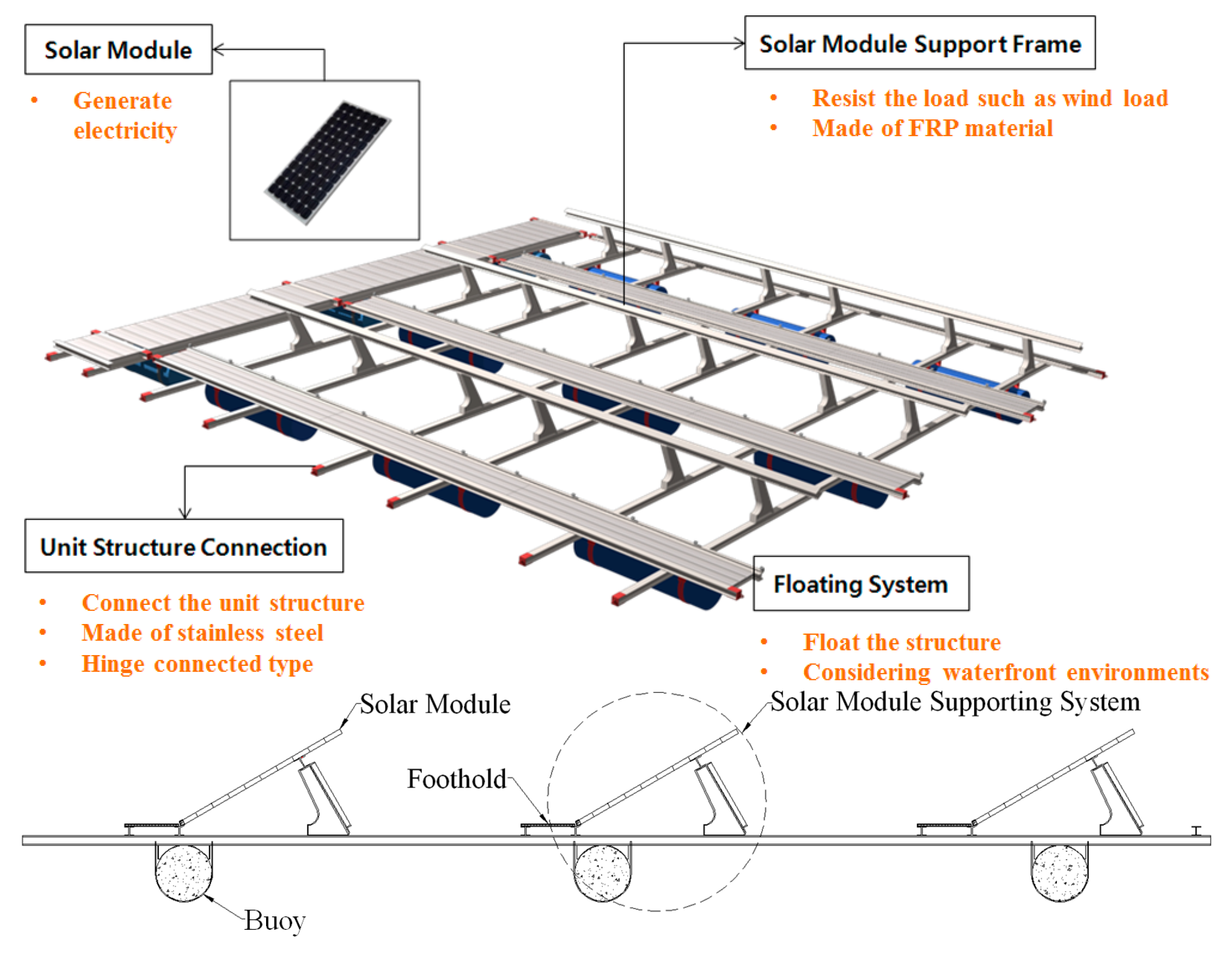
Unit structures consist of solar modules, structural systems to support the PV modules (which are composed of FRP structural members), a floating system, and connecting devices, as shown in Figure 1.
The FRP structural members are classified as vertical members, supporting members used to assemble the solar module, solar module connecting members used to assemble the solar module and foothold, foothold members to assemble the footholds and increase the horizontal stiffness of the structures, and main members to assemble the other members and the buoy. All structural members are connected using stainless steel bolts. The length of the structural members is set to 12.6 m for easy handling during fabrication of the structural system.
The 1 MW class floating PV generation complex consists of unit structures that are 12.6 m in length and 11.5 m in width. The unit structure has a 300 W generation capacity, in which 33 solar panels with dimension of 1966 mm × 1000 mm per panel are installed.
2.2. Complex Composition
The 1 MW class floating PV generation complex was constructed at Dangjin-city, Korea. The construction site of the 1 MW class floating PV generation complex is shown in Figure 2.
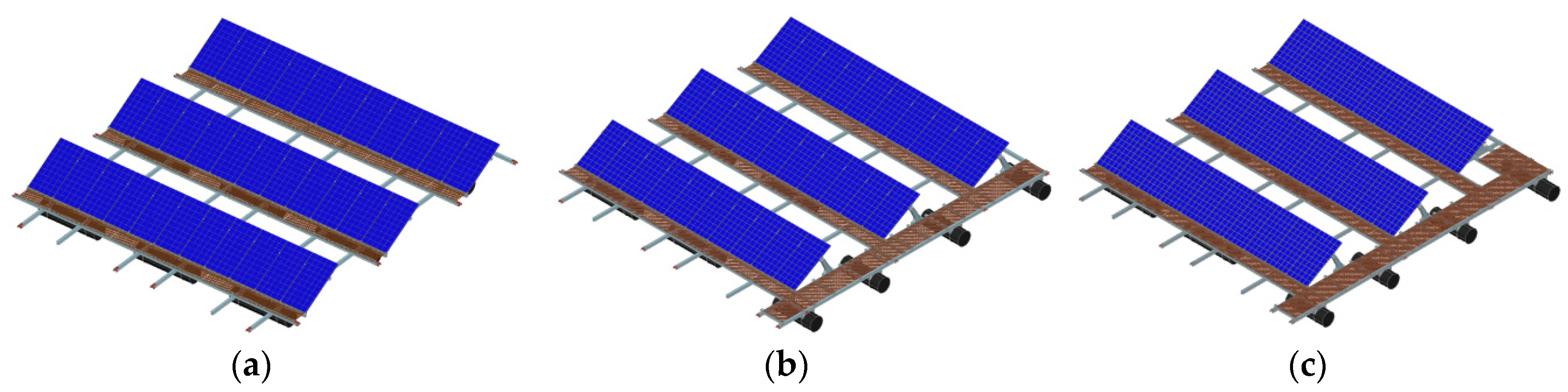
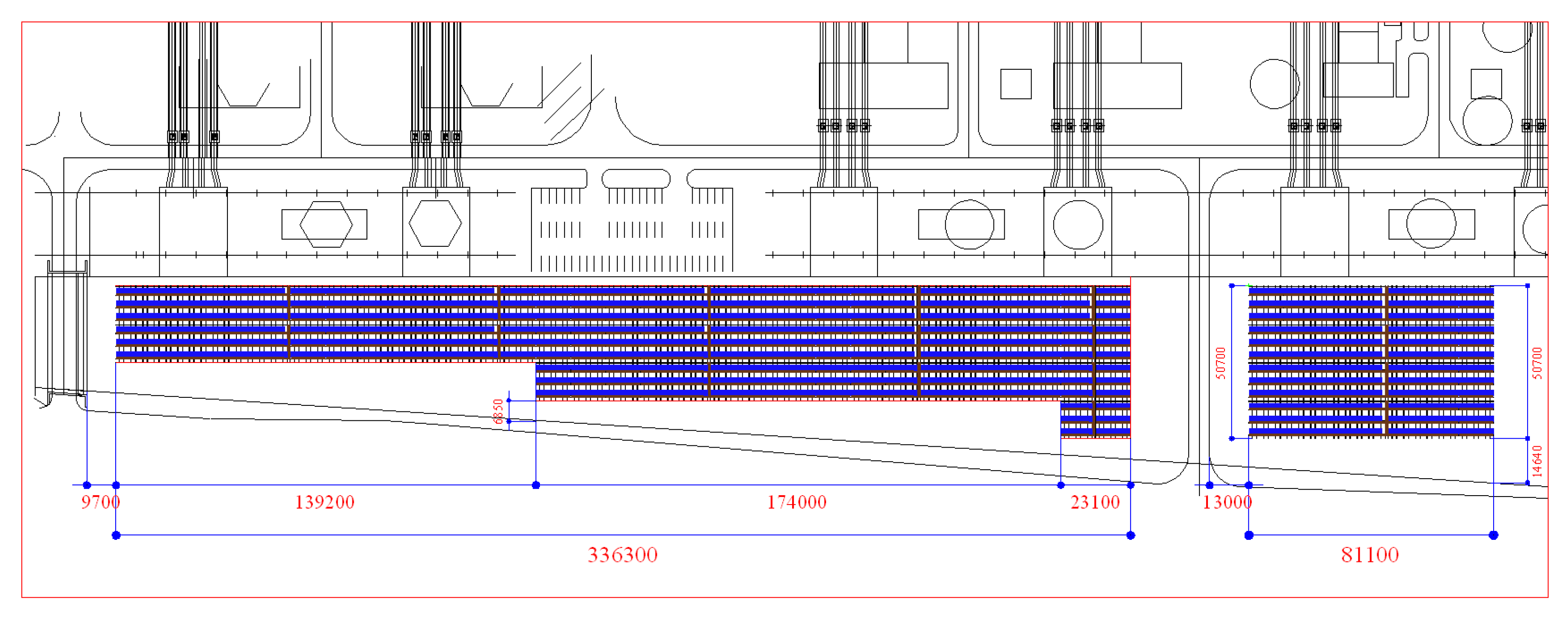
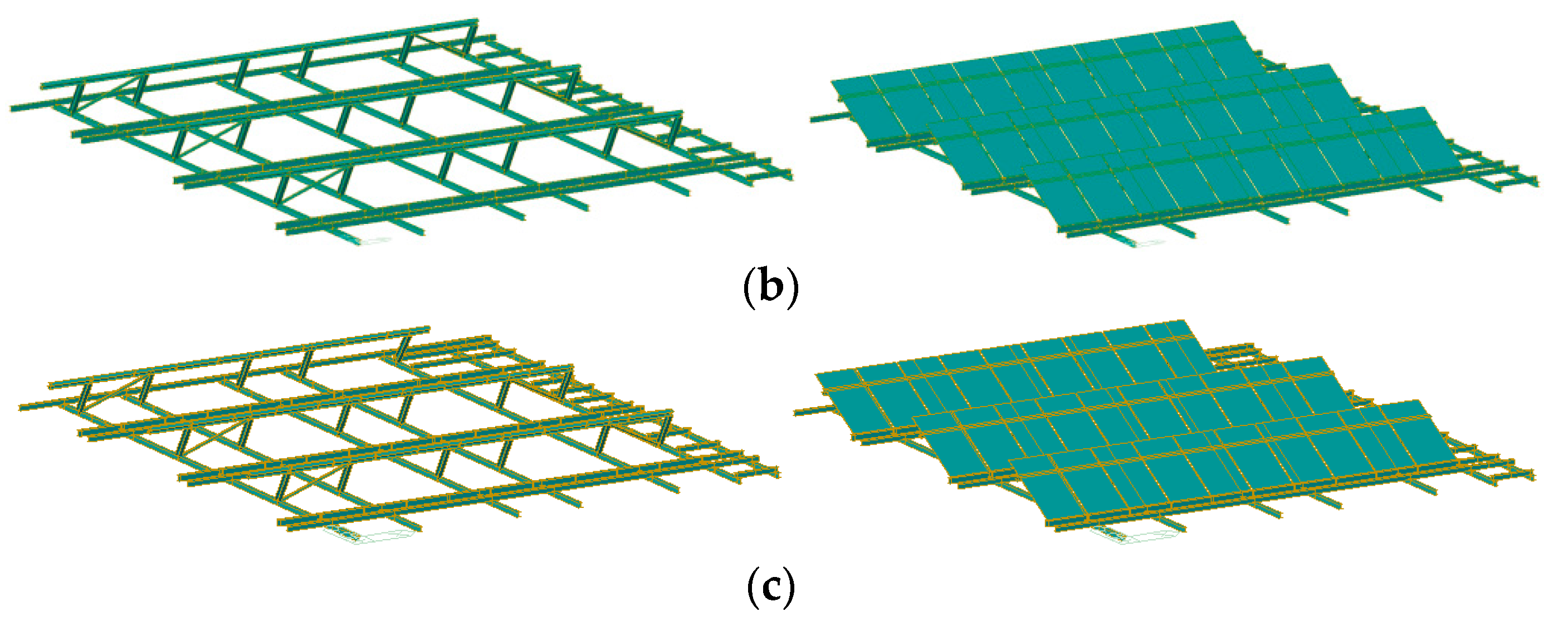
The 1 MW class floating PV generation complex consists of 105 unit structures, which are classified into three types: A, B, and C types. The A type is the basic model, the B type is the combination of the A-type and a pontoon bridge, and the C type is the structure used to install electrical devices such as the converter, as shown in Figure 3. The pontoon bridge is constructed to install the electrical equipment and is also used as movement route for the workers. The generation capacity of each unit structure type is given in Table 1. The total arrangement of the generation complex composition is shown in Figure 4.
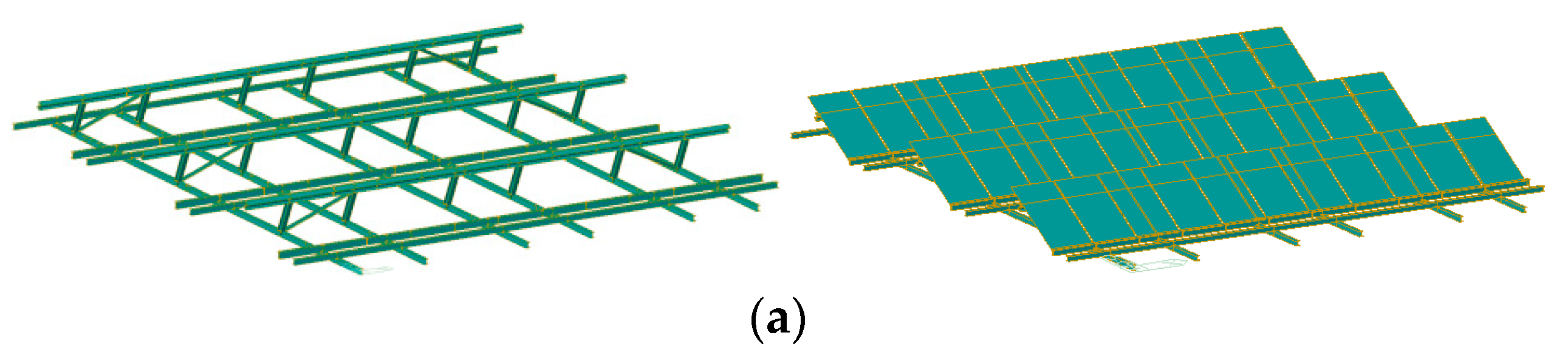
The finite element (FE) analyses of the unit structures shown in Figure 3 are conducted using the most intelligent design and analysis system (MIDAS Civil 2012) [7]. The results of the FE analyses are used for structural design; the safety of the unit structures is estimated by the allowable stress design (ASD) according to the Structural Plastic Design Manual [8]. The mechanical properties and allowable stress of the FRP structural members are given in Table 2 and Table 3, respectively [9]. In addition, the FE analysis model is shown in Figure 5.
Wind load for the design of the unit structures is determined based on the wind speed of 30 m/sec according to the requirements in the Korean Building Code and Commentary [10]. The design wind load at the construction site (Dangjin-city, Korea) is suggested in the Korean Building Code and Commentary [10]. In addition, snow load (0.4 kN/m2) is applied on the PV module and foothold. Crowd load (4.9 kN/m2) is additionally applied on the foothold. Snow load and crowd load are determined according to the Korean Building Code and Commentary [10] and the Korean Bridge Design Specification [11].
From the FE analysis results, it was found that the ratio of the maximum stress to the allowable stress occurring on the A-type structure is 47.73%; on the B-type structure this value is 45.68%; and on the C-type structure this value is 46.02% as shown in Table 4. Shear stress on the PFRP member in each type of structure was the critical stress governing the structural behavior. Therefore, according to the FE analysis results, it was also found that the strength and stiffness of the PFRP and SMC FRP structural members are acceptable for the design and fabrication of the system.
2.3. Design of Connection System
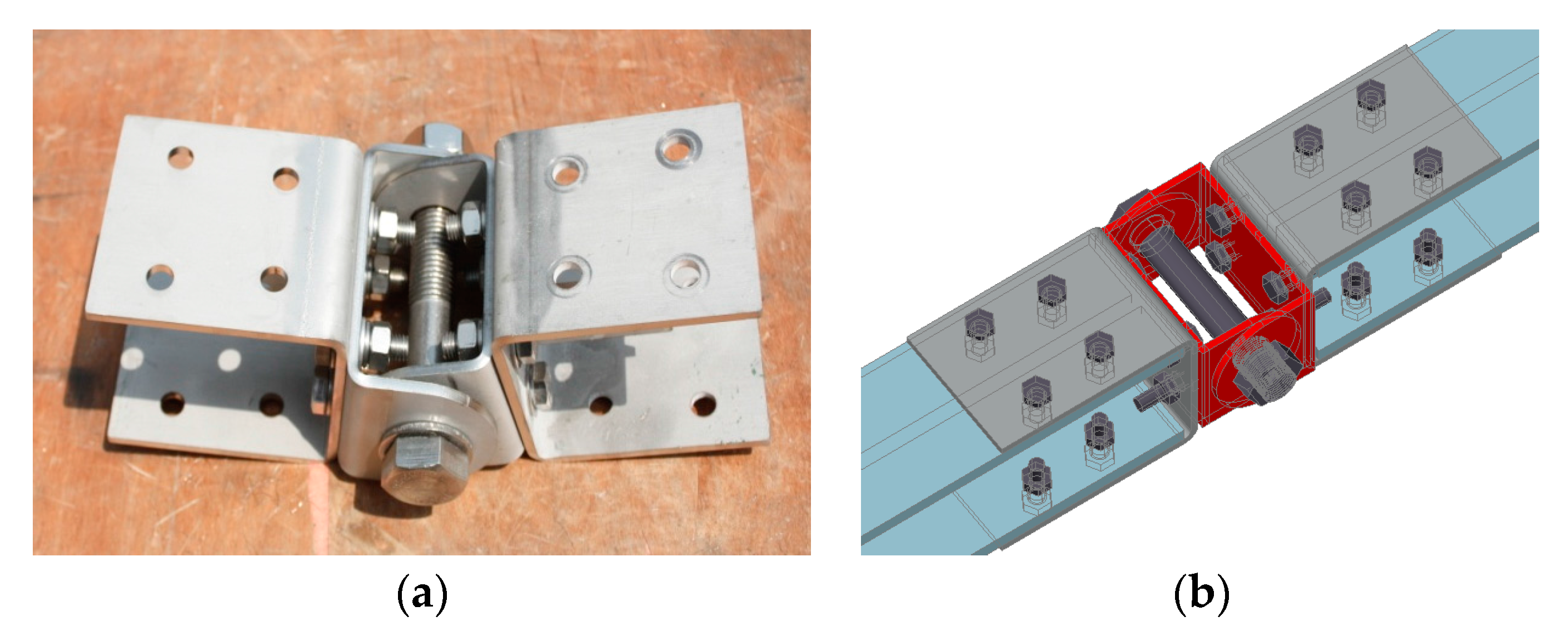
The 1 MW class floating PV generation complex is composed of unit structures that are connected using the connection system shown in Figure 6. The connection system is devised to minimize welding and increase the fatigue resistance. Moreover, a C-shape device made of stainless steel (STS304), which has high corrosion resistance, is connected using stainless steel bolts. The C-shape device can be made by cutting a stainless steel plate. This connection system behaves as a bending moment free system on the fluctuating water surface.
Structural design using the connection system suggested is conducted according to the Pre-Standard for Load and Resistance Factor Design of Pultruded Fiber Reinforced Polymer Structures [12]. American Society of Civil Engineers (ASCE) [12] suggests that the connection system may use the minimum requirements for bolted connection geometries, as shown in Table 5. In Table 5, end distance, edge distance, stagger distance, pitch, and gage are given; notations are illustrated in Figure 7. In addition, bolt shear strength, pin-bearing strength, net tension strength, shear-out strength, and block shear strength must also be considered. The final results of the design of connection system are given in Table 6.
2.4. Design of Mooring System
The mooring systems of the floating structures that are installed at the dam or reservoir may be classified into gravity type, anchor-tension type, semi-rigid type, tension type, and modified type [13]. In the mooring systems, the anchor-tension type using an anchor is generally applied. However, the fluctuation of the water level at the construction site of the 1 MW class floating PV generation complex is less severe than that of a dam or reservoir. The tension type mooring system is not applicable to the present construction site. Therefore, for the safe and commercial design of the mooring system, the anchor-tension type, which is fixed with a chemical anchor and cable to the wall of the waterway in the cooling water intake channel, is adopted.
The anchor-tension type mooring system for the 1 MW class floating PV generation complex is shown in Figure 8. In Figure 8, the level of the chemical anchor is similar to the level of the PFRP member; therefore, cable (wire rope) is attached to maintain a constant tension force in the cable, as shown in Figure 8. The level of the PFRP member is determined by referring to the observation source, which indicates the average water level of the site.
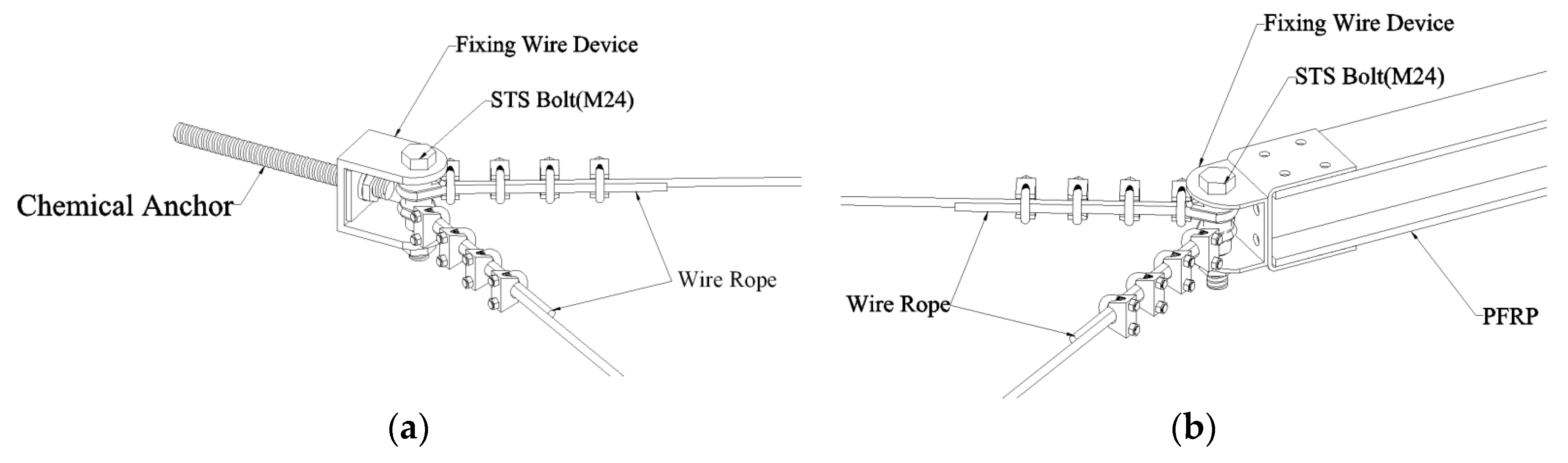
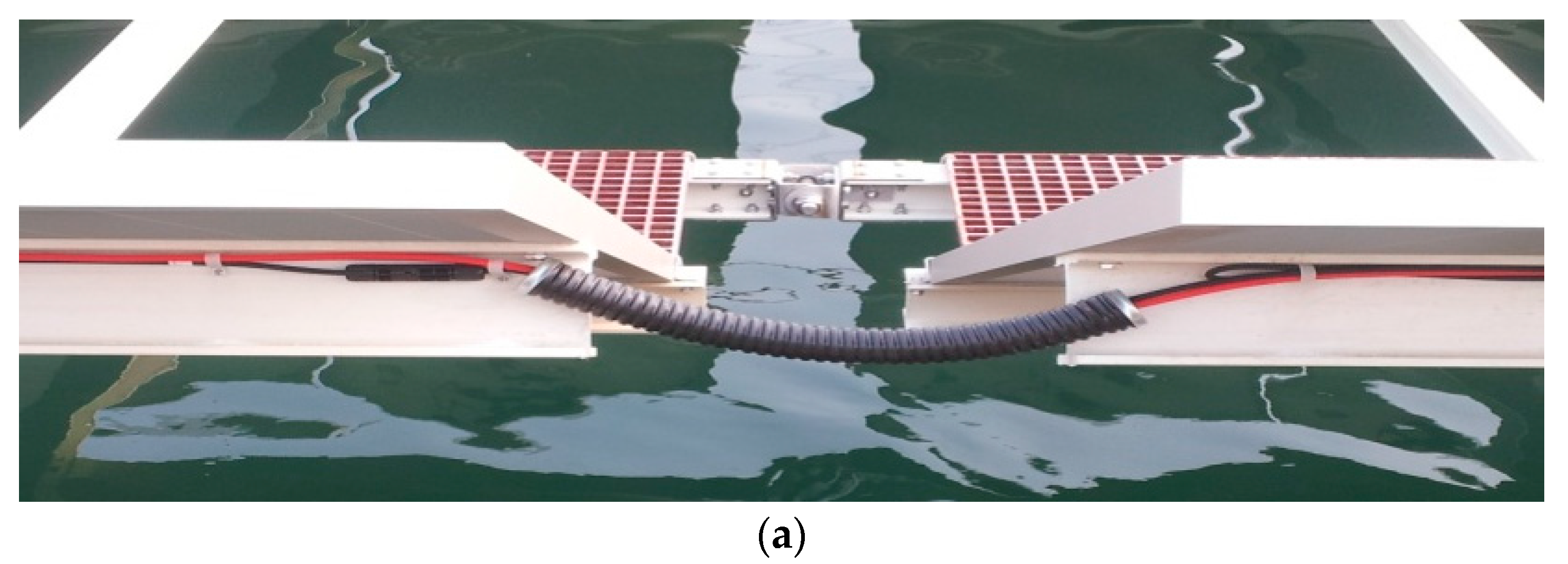
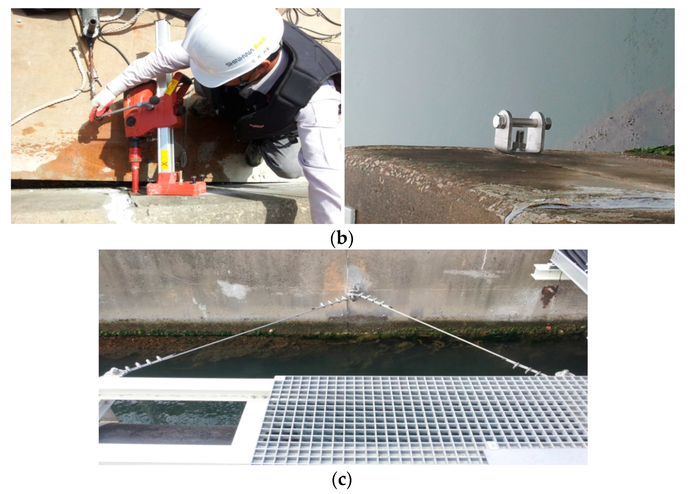
Connection methods between the chemical anchor or the PFRP member and the wire rope are shown in Figure 9. All connection devices are made of stainless steel (STS304), which is cut and bent from stainless steel plate.
According to the Ministry of Land, Infrastructure, and Transport, Korea (2008), the criteria concerning structures, facilities, etc., of a floating maritime type is specified by the weight of the anchor and the type of cable. The weight of the anchor and the type of rope for floating type maritime structures are determined according to the flowchart shown in Figure 10. In Figure 10, the total resistance (R) is determined by combining the wind resistance (), flow resistance (), and effect of the shape of the structure () as given in Equation (1).
In Figure 2, the construction site can be seen to be separated from an existing bridge. In the design of the system, the effect of the horizontal and vertical directions of the water flow should be considered. The result of the mooring system design is given in Table 7. In Table 7, the diameter of the cable is 10 mm; the safety factor (S.F.) of the cable is 2.
The total number of cables installed is 60; this is more than specified by the design results (50). The plan view of the mooring system is given in Figure 11. At each mooring point, the number of connected cables at the anchor is between one and three, and the length of the cable is determined by the distance between the anchor and the PFRP member.
3. Construction of 1 MW Class Floating PV Generation System
The 1 MW class floating PV generation complex consists of 105 unit structures, as mentioned earlier. The construction process of the 1 MW class floating PV generation complex is classified into the following steps: “fabrication,” in which each unit structure is fabricated on the ground, “lifting and launching,” in which the fabricated unit structure is lifted and launched onto the water surface, and “mooring,” in which each unit structure and moor is connected using anchors and cables.
In the fabrication process, unit structures are fabricated using FRP members, which are cut at the manufacturing facility. At first, plane frames are fabricated on the buoys. SMC FRP vertical members, PV modules, footholds, etc., are assembled in sequence. The fabrication process (A-type) is shown in Figure 12.
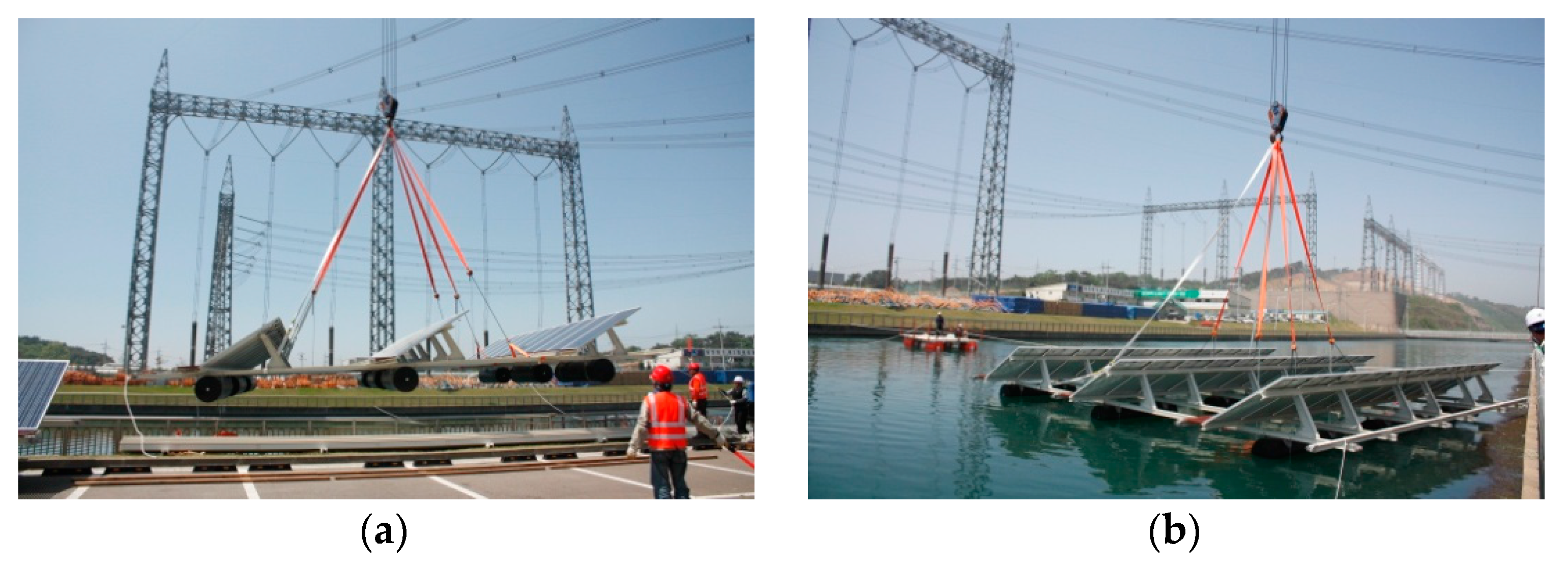
In the lifting and launching process, a crane is used to lift and launch the unit structures. To prevent unexpected accidents during the tilting and lifting operation, lifting points in the structure are selected by referring to the FE analysis results. The lifting and launching processes are shown in Figure 13.
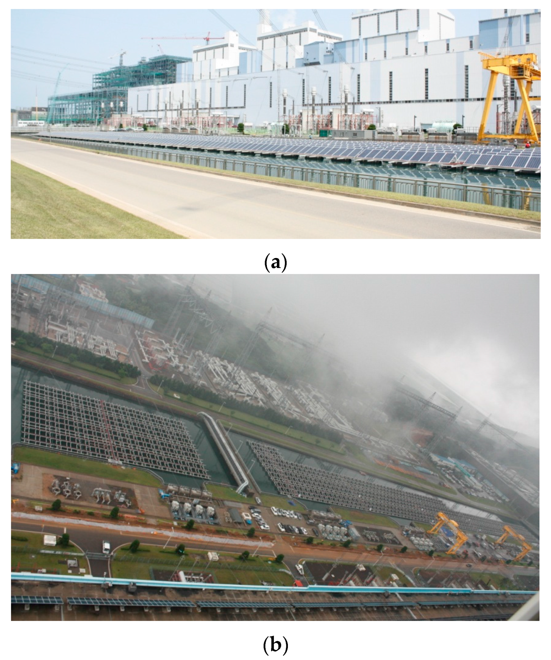
In the mooring process, all unit structures are connected using the connection system shown in Figure 6; chemical anchors are fixed on the wall of the waterway. Chemical anchors installed on the wall are connected to the cables as shown in Figure 9. The mooring process is also shown in Figure 14. Finally, the 1 MW class floating PV generation complex constructed at the site is shown in Figure 15.
4. Commercial Viability Evaluation of 1 MW Class Floating PV Generation System
In Korea, the electricity generated in power plants has to be sold to the Korea Electric Power Corporation (KEPCO) at a cost determined by the government. Therefore, the commercial viability evaluation of the 1 MW class floating PV generation complex through the generated electricity is not appropriate.
In this paper, structural analyses with various construction materials using the finite element method were performed to ascertain the safety of the floating PV generation structure, and a commercial viability evaluation was conducted based on the cost of materials. The construction materials used in the fabrication of floating PV generation structures are steel, aluminum, FRP, etc.
The material properties of steel, aluminum, and FRP are summarized in Table 8. The allowable stress of steel, aluminum, and FRP are also given in Table 9.
From the structural analyses, the cross-sectional dimensions of the member made of each material are determined; H-125 × 125 × 7 × 9 (in mm scale) for steel, H-100 × 100 × 10 × 10 (in mm scale) for FRP, and H-130 × 120 × 10 × 10 (in mm scale) for aluminum, respectively. The results of structural analyses are summarized in Table 10.
Buoys are made of high density polyethylene (HDPE) that are 590 mm in diameter and 2300 mm in length. Floating design is conducted to determine the number of buoys for the structural system made of each material. The results of the floating design are given in Table 11.
The commercial viability evaluation of floating PV generation complex is conducted by comparing the cost of materials (structural members and buoys). In the evaluation process, common items such as solar modules and mooring systems are excluded. In addition, in the evaluation, the durability of the material, their ease of handling due to light-weight of the material, etc., are not included.
From the results of the viability evaluation, the unit material cost of aluminum is higher than the FRP, and the unit cost of FRP is higher than the steel. However, the cost of aluminum members is higher than the steel members, and the cost of steel members is higher than the FRP members because of the difference of the unit weight (or specific gravity) of materials.
When a 1 MW class floating PV generation complex is constructed using FRP members, the total cost for structural system is 2.49 times lower than the steel members and 1.77 times lower than the aluminum members, mainly because of low specific gravity. Therefore, when a 1 MW class floating PV generation complex is constructed, it is estimated that FRP is the most cost effective material. The results of the commercial viability evaluation are summarized in Table 12.
5. Conclusions
In this paper, we present the design and construction process of a floating PV generation system with details of its actual construction. Moreover, we suggest the composition of the unit structure and the process for the construction of the large-scale floating PV generation complex.
The 1 MW class floating PV generation complex is not constructed at a dam or reservoir, but is constructed at the waterway of the cooling water intake channel in a thermoelectric power plant. Considering the site conditions, anchors of the tension type that can be fixed to the wall of the waterway using a chemical anchor and cable are adopted. The 1 MW class floating PV generation complex is designed to consider the conditions of the construction site and to promote the commercialization of the floating PV system.
A brief commercial viability analysis was performed based on the material costs of the structural system fabricated with different materials. It found that the structural system fabricated with FRP is the most cost effective due to the light weight of the material.
For the commercialization of a large-scale floating PV generation systems using FRP members, it may be necessary to develop appropriate elemental techniques, construction skills, mooring systems, etc. Therefore, the design and construction techniques developed in the 1 MW class floating PV generation complex may be positive examples for the construction of large-scale floating PV generation complexes in the future.
Acknowledgments
This work is supported by the Korea Agency for Infrastructure Technology Advancement (KAIA) grant funded by the Ministry of Land, Infrastructure and Transport (Grant 17AUDP-B099686-03).
Author Contributions
S.J. Yoon contributed to conception and design and acquisition of data; S.H. Kim wrote the paper; W. Choi critically revised the paper.
Conflicts of Interest
The authors declare no conflict of interest.
References
- Choi, H.; Joo, H.J.; Nam, J.H.; Kim, K.S.; Yoon, S.J. Structural Design for the Development of the Floating Type Photovoltaic Energy Generation System. Mater. Sci. Forum 2010, 654–656, 2803–2806. [Google Scholar] [CrossRef]
- Nam, J.H. Development of Floating Type Photovoltaic Energy Generation System Using the Pultruded Structural Members. Ph.D. Thesis, Hongik University, Seoul, Korea, 2010. [Google Scholar]
- Korean Bridge. Design Specification; Korea Road and Transportation Association: Seongnam, Korea, 2012.
- Galdino, M.A.E.; Olivieri, M.M.A. Some Remarks about the Deployment of Floating PV Systems in Brazil. J. Electr. Eng. 2017, 1, 10–19. [Google Scholar] [CrossRef]
- Jones, R.M. Mechanics of Composite Materials, 2nd ed.; Taylor & Francis: Philadelphia, PA, USA, 1998. [Google Scholar]
- Yoon, S.J. Estimation of Structural Behavior for the Floating PV Generation System with High. Durability, Technical Report; Shinhwa E&E and ISIS E&C: Seoul, Korea, 2013. (In Korean) [Google Scholar]
- Analysis Reference; MIDAS IT: Seoul, Korea, 2012. (In Korean)
- Structural Plastic Design Manual-ASCE Manual and Reports on Engineering Practice No. 63; American Society of Civil Engineers (ASCE): Reston, VA, USA, 1984.
- Choi, J.W.; Joo, H.J.; Nam, J.H.; Hwang, S.T.; Yoon, S.J. Performance Enhancement of Floating PV Generation Structure Using FRP. Compos. Res. 2012, 26, 105–110. (In Korean) [Google Scholar] [CrossRef]
- Korean Building Code and Commentary; Architectural Institute of Korea: Seoul, Korea, 2009.
- Pre-Standard for Load and Resistance Factor Design of Pultruded. Fiber Reinforced Polymer Structures; American Society of Civil Engineers (ASCE): Reston, VA, USA, 2010.
- Kim, J.H.; Kim, H.J.; Hong, S. Experiment and Analysis of Mooring System for Floating Fish Cage. J. Korean Soc. Fish. Aquat. Sci. 2001, 34, 661–665. [Google Scholar]
- Song, J.Y.; Choi, Y.S. Analysis of the Potential for Use of Floating Photovoltaic Systems on Mine Pit Lakes: Case Study at the Ssangyong Open-Pit Limestone Mine in Korea. Energies 2016, 9, 102. [Google Scholar] [CrossRef]
Figure 1.
Composition of unit structure [6].
Figure 1.
Composition of unit structure [6].

Figure 2.
Construction site.
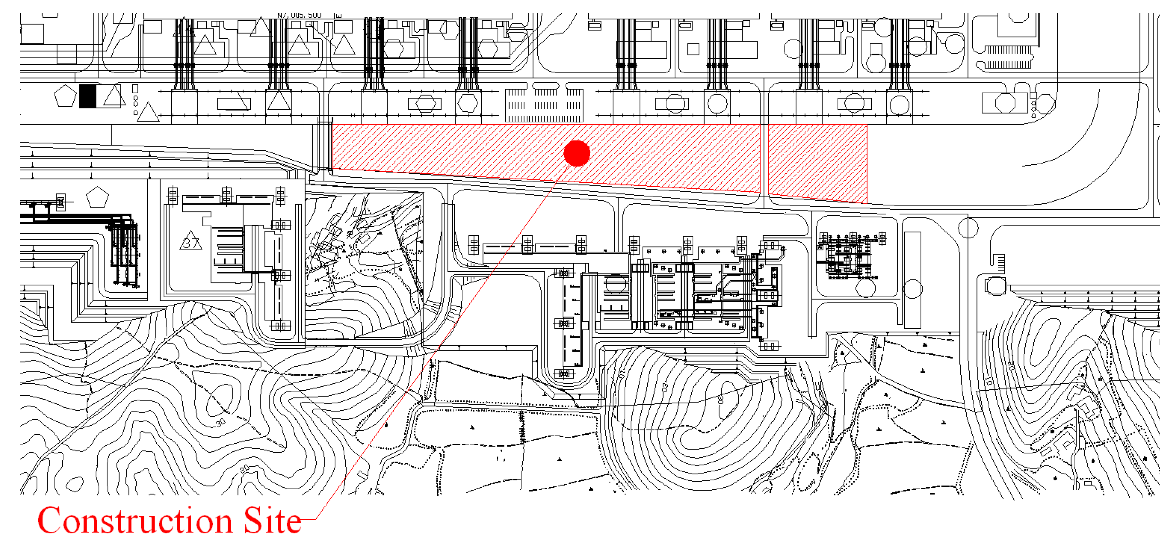
Figure 3.
Unit structure (a) A type (basic mode); (b) B type (with foothold); (c) C type (to install electric device) [6].
Figure 3.
Unit structure (a) A type (basic mode); (b) B type (with foothold); (c) C type (to install electric device) [6].

Figure 4.
Composition of floating PV generation complex (Unit: mm).

Figure 5.
Finite element (FE) analysis model; (a) A type; (b) B type; (c) C type.


Figure 6.
Connection system between unit structures; (a) C-shape device; (b) Member connected with C-shape device.
Figure 6.
Connection system between unit structures; (a) C-shape device; (b) Member connected with C-shape device.

Figure 7.
Connection geometry and definition for a row of bolts [12].
Figure 7.
Connection geometry and definition for a row of bolts [12].
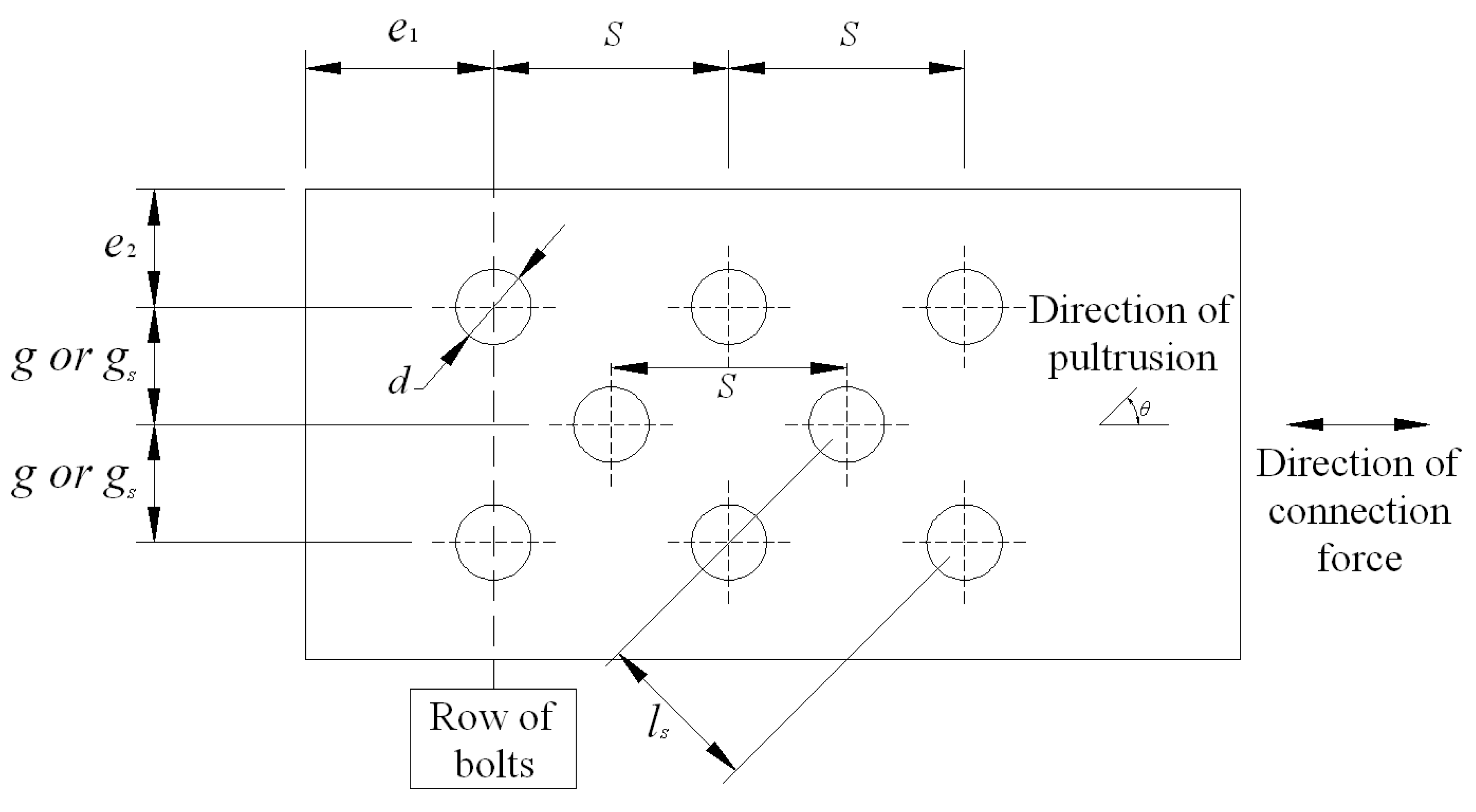
Figure 8.
Anchor mooring system.
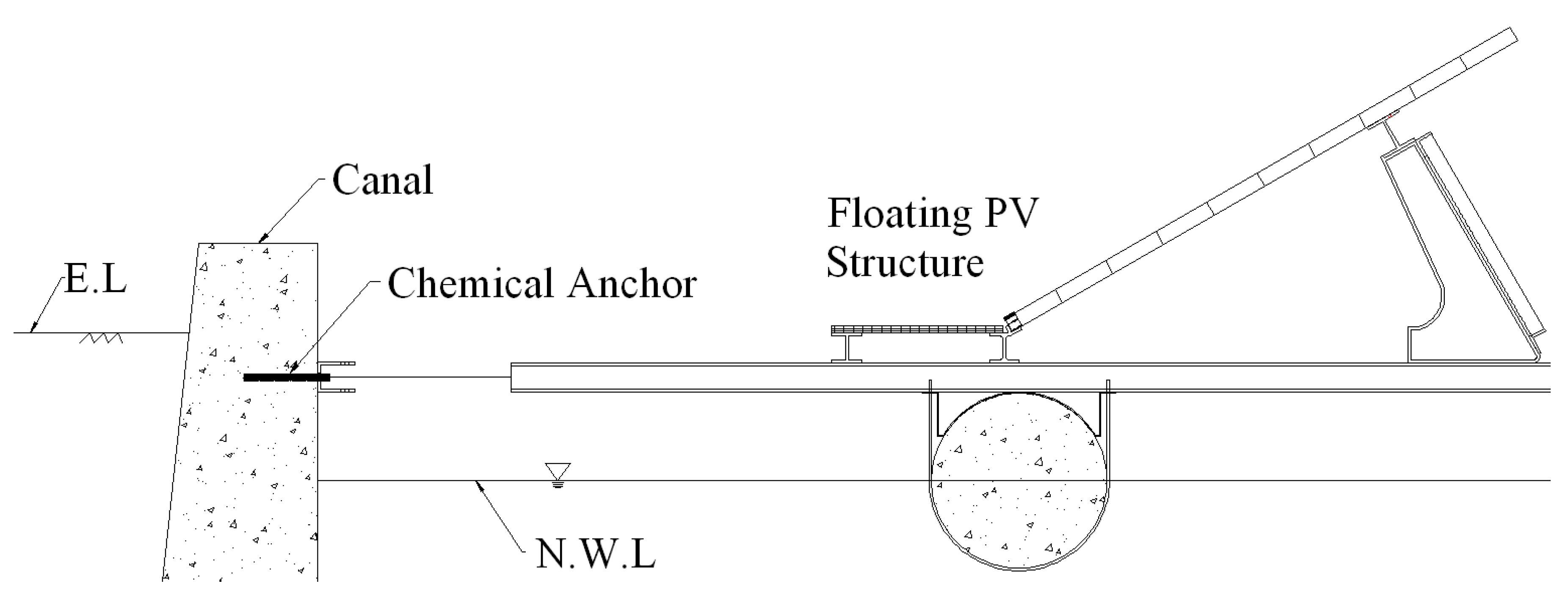
Figure 9.
Connection of mooring system; (a) Between chemical anchor and cable; (b) Between PFRP member and cable.
Figure 9.
Connection of mooring system; (a) Between chemical anchor and cable; (b) Between PFRP member and cable.

Figure 10.
Flowchart for mooring system design [2].
Figure 10.
Flowchart for mooring system design [2].
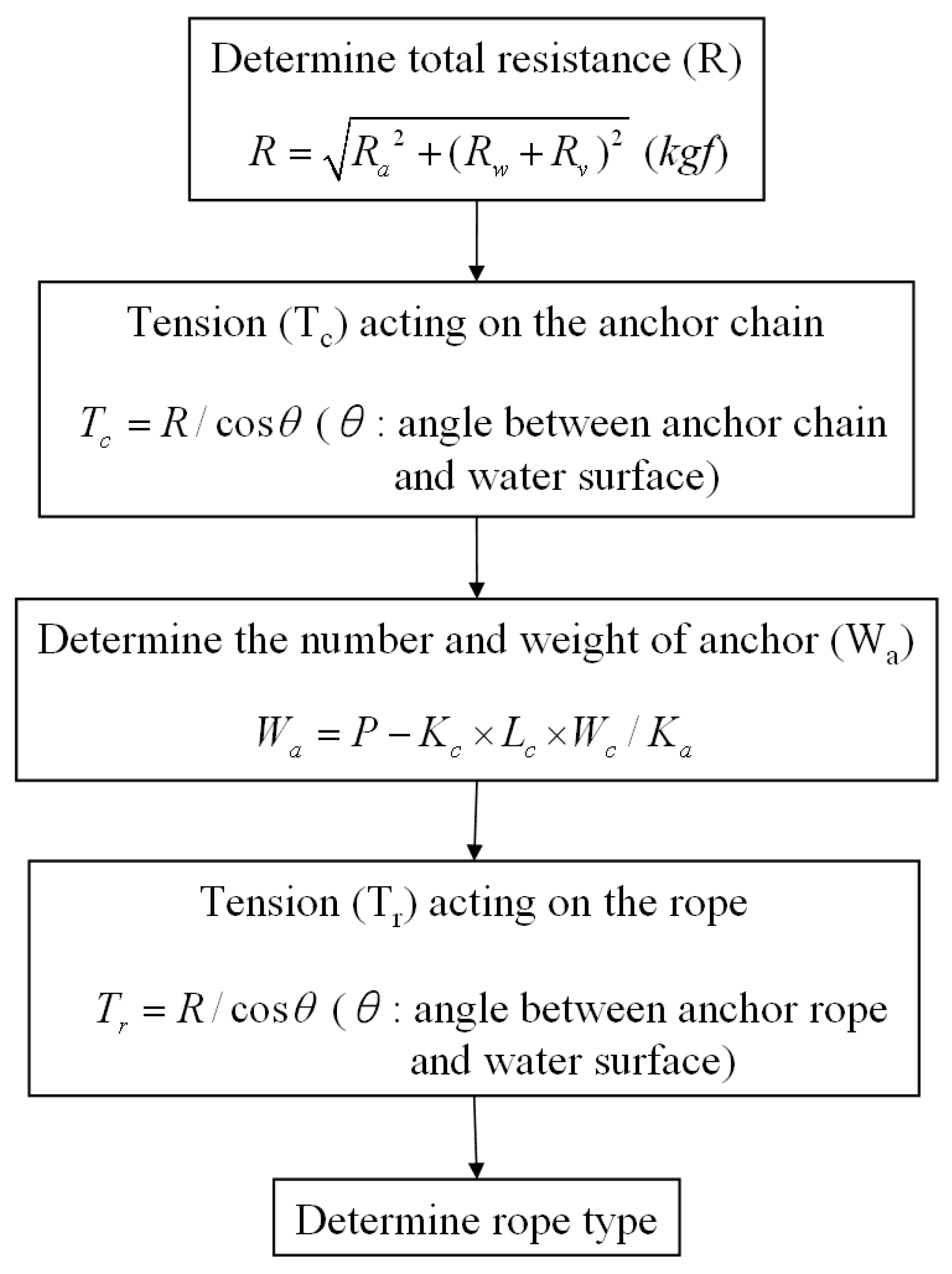
Figure 11.
Mooring system of 1 MW class floating PV generation system.
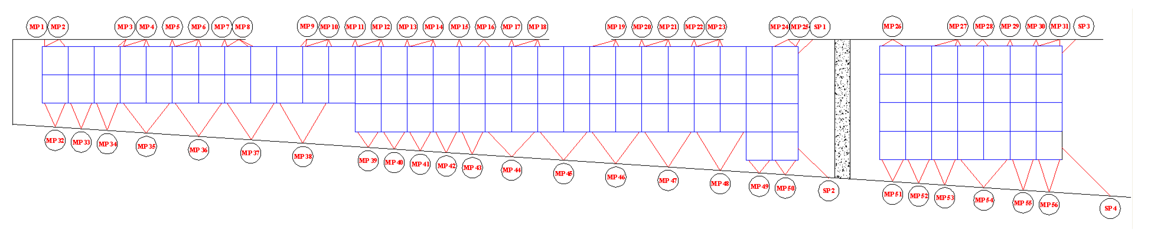
Figure 12.
Fabrication process; (a) Fabricating plane frame; (b) Assembling buoy; (c) Assembling foothold; (d) Assembling SMC FRP member; (e) Assembling module support frame; (f) Assembling solar module.
Figure 12.
Fabrication process; (a) Fabricating plane frame; (b) Assembling buoy; (c) Assembling foothold; (d) Assembling SMC FRP member; (e) Assembling module support frame; (f) Assembling solar module.
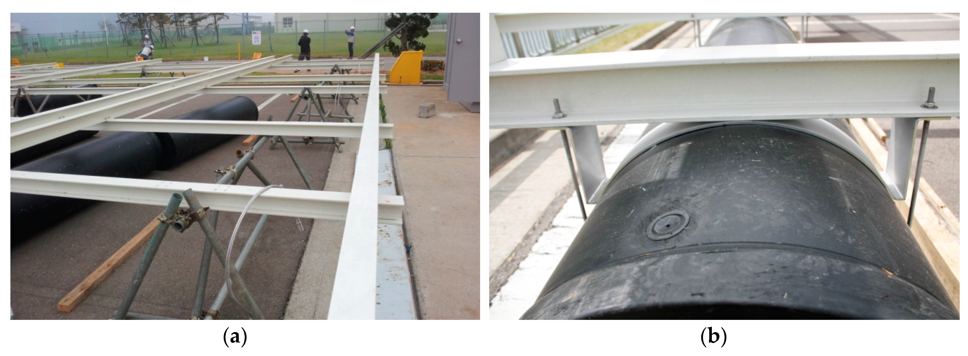
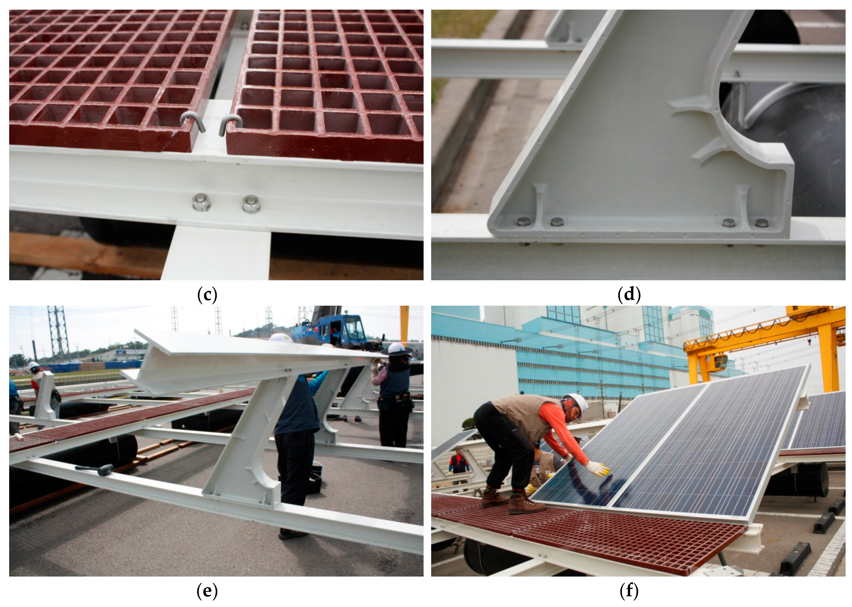
Figure 13.
Lifting and launching process; (a) Lifting; (b) Launching.

Figure 14.
Mooring process; (a) Connecting; (b) Anchoring; (c) Mooring.


Figure 15.
1 MW class floating PV generation complex; (a) Side view; (b) Top view.

Table 1.
No. and generation capacity of each unit structure.
| Type | A-Type | B-Type | C-Type |
|---|---|---|---|
| No. of unit structure (EA) | 89 | 6 | 12 |
| No. of solar module per unit structure (EA) | 33 | 30 | 29 |
| Generation capacity per unit structure (kW) | 9.9 | 9.0 | 8.7 |
Table 2.
Mechanical properties.
| Mechanical Properties | PFRP | SMC FRP |
|---|---|---|
| Elastic modulus (E, GPa) | 33.28 | 17.33 |
| Tensile strength (ft, MPa) | 402.58 | 183.85 |
| Shear strength (fv, MPa) | 79.20 | 34.47 |
| Poisson’s ratio (ν, mm/mm) | 0.25 | 0.25 |
| Unit weight (G, kN/m2) | 18.42 | 18.42 |
Table 3.
Allowable stress.
| Allowable Stress | PFRP | SMC FRP | S.F. |
|---|---|---|---|
| Tension (MPa) | 201.29 | 91.93 | 2.0 |
| Compression (MPa) | 134.19 | 61.28 | 3.0 |
| Shear (MPa) | 26.40 | 11.49 | 3.0 |
| Flexure (MPa) | 161.03 | 73.54 | 2.5 |
Table 4.
FE analysis results.
| Stress | A-Type (MPa) | B-Type (MPa) | C-Type (MPa) | Allowable Stress (MPa) | ||
|---|---|---|---|---|---|---|
| Tension | PFRP | 1.32 | 2.89 | 2.89 | 2.89 | |
| SMC FRP | 0.00 | 0.00 | 0.00 | 0.00 | ||
| Compression | PFRP | 1.79 | 6.90 | 6.94 | 6.94 | |
| SMC FRP | 1.52 | 1.42 | 1.41 | 1.41 | ||
| Shear | PFRP | 12.60 | 12.06 | 12.15 | 12.15 | |
| SMC FRP | 0.36 | 1.53 | 2.17 | 2.17 | ||
| Flexure | PFRP | 25.86 | 24.36 | 24.59 | 24.59 | |
| SMC FRP | 2.51 | 8.43 | 11.91 | 11.91 | ||
| Remark | OK | OK | OK | - | ||
Table 5.
Minimum requirements of bolted connection geometries.
| Notation | Definition | Minimum Required Spacing (mm) | Distance of Suggested Connection (mm) | Remark | |
|---|---|---|---|---|---|
| e1,min | End distance of all connections | 2.0d | 20 | 40 | OK |
| e2,min | Edge distance | 1.5d | 15 | 20 | OK |
| smin | Pitch distance | 4.0d | 40 | 50 | OK |
| gmin | Gage distance | 4.0d | 40 | 50 | OK |
| gs,min | Gage spacing with staggered bolts | 2.0d | 20 | 50 | OK |
| ls,min | Stagger distance | 2.8d | 28 | 74 | OK |
Table 6.
Result of design on the connection system.
| Step | Consideration | Load | Note |
|---|---|---|---|
| Checking the failure mode | Bolt failure (kN) | 65.16 | N/A |
| Pin-bearing failure (kN) | 128.83 | N/A | |
| Net tension failure (kN) | 58.24 | N/A | |
| Shear-out failure (kN) | 101.21 | N/A | |
| Block shear failure (kN) | 57.81 | Failure mode | |
| Connection design | Critical load (kN) | 57.24 | N/A |
| Design load (kN) | 46.25 | A | |
| Applied load (kN) | 29.82 | B | |
| Remark | OK | - | |
| A/B | 1.55 | - |
Table 7.
Result of mooring system design.
| Location | Left | Right | ||
|---|---|---|---|---|
| Direction | Horizontal | Vertical | Horizontal | Vertical |
| Total resistance (kN) | 556.15 | 13.92 | 136.61 | 13.82 |
| Design strength of cable (kN) | 20.97 | 9.31 | 20.97 | 9.31 |
| No. of cable (EA) | 38 | 12 | ||
| Mooring load (kN) | 796.74 | 363.09 | 251.66 | 111.72 |
| Remark | OK | OK | OK | OK |
Table 8.
Mechanical properties of steel, aluminum, and fiber reinforced polymer (FRP).
| Material | Yield Strength (MPa) | Elastic Modulus (E, GPa) | Unit Weight (G, kN/m2) | |
|---|---|---|---|---|
| Steel | SS400 | 280.00 | 200.00 | 76.91 |
| Aluminum | 6063-T6 | 170.00 | 69.60 | 26.49 |
| FRP | GFRP | 402.58 | 33.28 | 18.42 |
Table 9.
Allowable stress of steel, aluminum, and FRP.
| Allowable Stress | Tension (MPa) | Compression (MPa) | Shear (MPa) | Flexure (MPa) | |
|---|---|---|---|---|---|
| Steel | SS400 | 140.00 | 140.00 | 80.00 | 140.00 |
| Aluminum | 6063-T6 | 103.03 | 103.03 | 61.82 | 103.03 |
| FRP | GFRP | 201.29 | 134.19 | 26.40 | 161.03 |
Table 10.
FE analysis results of steel, aluminum, and FRP.
| Material | Tension (MPa) | Compression (MPa) | Shear (MPa) | Flexure (MPa) | Remark |
|---|---|---|---|---|---|
| Steel | 30.02 | 28.94 | 30.38 | 116.24 | OK |
| Aluminum | 15.43 | 15.24 | 13.20 | 89.04 | OK |
| FRP | 1.32 | 1.79 | 12.60 | 25.86 | OK |
Table 11.
Results of the floating design.
| Material | Length of Buoys (mm) | No. of Buoys (EA) | No. of Structures (EA) | Total No. of Buoys (EA) | Total Volume (m3) |
|---|---|---|---|---|---|
| Steel | 2300 | 39 | 105 | 4095 | 2574.99 |
| Aluminum | 14 | 1470 | 924.36 | ||
| FRP | 9 | 945 | 594.23 |
Table 12.
Commercial viability evaluation of floating PV generation complex.
| Material | Steel | Aluminum | FRP |
|---|---|---|---|
| Self weight of structure (kN) | 48.84 | 17.60 | 11.48 |
| Unit cost of member (US$/N) | 0.16 | 0.54 | 0.44 |
| No. of structures (EA) | 105 | ||
| Cost of members (US$) | 820,512 | 997,920 | 530,376 |
| Unit cost of buoy (US$) | 285 | ||
| Total No. of buoys (EA) | 4095 | 1470 | 945 |
| Cost of buoys (US$) | 1,167,075 | 418,950 | 269,325 |
| Total Cost (US$) | 1,987,587 | 1,416,870 | 799,701 |
© 2017 by the authors. Licensee MDPI, Basel, Switzerland. This article is an open access article distributed under the terms and conditions of the Creative Commons Attribution (CC BY) license (http://creativecommons.org/licenses/by/4.0/).
Share and Cite
MDPI and ACS Style
Kim, S.-H.; Yoon, S.-J.; Choi, W. Design and Construction of 1 MW Class Floating PV Generation Structural System Using FRP Members. Energies 2017, 10, 1142. https://doi.org/10.3390/en10081142
AMA Style
Kim S-H, Yoon S-J, Choi W. Design and Construction of 1 MW Class Floating PV Generation Structural System Using FRP Members. Energies. 2017; 10(8):1142. https://doi.org/10.3390/en10081142
Chicago/Turabian StyleKim, Sun-Hee, Soon-Jong Yoon, and Wonchang Choi. 2017. "Design and Construction of 1 MW Class Floating PV Generation Structural System Using FRP Members" Energies 10, no. 8: 1142. https://doi.org/10.3390/en10081142
Note that from the first issue of 2016, this journal uses article numbers instead of page numbers. See further details here.