Frequency Regulation Strategies in Grid Integrated Offshore Wind Turbines via VSC-HVDC Technology: A Review


1
Power Electronics and Renewable Energy Research Laboratory (PEARL), Department of Electrical Engineering, University of Malaya, Kuala Lumpur 50603, Malaysia
2
Department of Electrical Engineering, University of Malaya, Kuala Lumpur 50603, Malaysia
*
Author to whom correspondence should be addressed.
Energies 2017, 10(9), 1244; https://doi.org/10.3390/en10091244
Submission received: 16 June 2017
/
Revised: 17 August 2017
/
Accepted: 18 August 2017
/
Published: 23 August 2017
(This article belongs to the Special Issue Emerging Power Electronics Technologies for Power Systems and Machine Drives)
Abstract
:The inclusion of wind energy in a power system network is currently seeing a significant increase. However, this inclusion has resulted in degradation of the inertia response, which in turn seriously affects the stability of the power system’s frequency. This problem can be solved by using an active power reserve to stabilize the frequency within an allowable limit in the event of a sudden load increment or the loss of generators. Active power reserves can be utilized via three approaches: (1) de-loading method (pitching or over-speeding) by a variable speed wind turbine (VSWT); (2) stored energy in the capacitors of voltage source converter-high voltage direct current (VSC-HVDC) transmission; and (3) coordination of frequency regulation between the offshore wind farms and the VSC-HVDC transmission. This paper reviews the solutions that can be used to overcome problems related to the frequency stability of grid- integrated offshore wind turbines. It also details the permanent magnet synchronous generator (PMSG) with full-scale back to back (B2B) converters, its corresponding control strategies, and a typical VSC-HVDC system with an associated control system. The control methods, both on the levels of a wind turbine and the VSC-HVDC system that participate in a system’s primary frequency control and emulation inertia, are discussed.
1. Introduction
The global energy consumption has resulted in the depletion of fossil fuel reserves and the increase in CO2 emissions [1]. The detrimental effect of greenhouse gas emissions on the environment has prompted many countries to amend their respective energy policies to include more renewable sources. Wind energy represents a viable option for many countries [2] due to its ubiquity, and its viability for supporting and improving the reliability of an electrical power system. In 2014, the installed offshore wind energy output 8759 MW, representing 2% of the total installed wind power capacity in the world [3,4]. This amount is expected to increase in the near future. ~90% of offshore wind parks are located in the North, Baltic, and Irish Seas, and the English Channel [5]. There are also strong interests from regions such as Asia and the America. Figure 1 shows the installed onshore and offshore wind power capacity forecast in Europe until 2030 [6].
Variable speed operation of a wind turbine results in favorable outcomes such as reduced friction, mechanical stress, noise, maintenance, and improved efficiency and reliability. Currently, there are two most commonly used variable speed wind turbine generator systems, which are detailed below.
The first wind turbine generator for variable speed is the doubly fed induction generator (DFIG). It is commonly used in variable-speed wind energy applications with a back to back (B2B) power electronic converter. DFIG comprises two parts; the stator windings are connected directly to the AC grid via a transformer, while the rotor windings are connected to the AC grid via slip rings and three phase power electronic converters. The main and important feature of DFIG is that it is able to achieve a maximum energy conversion-efficiency over a wide range of wind speeds [7]. This type of variable speed wind turbine power generation system uses a multi-stage gearbox and partial-scale power electronic converter to connect of the wind turbine generator to the AC load/grid.
The second type of wind turbine based on a variable speed wind energy conversion system (WECS) is a permanent magnet synchronous generator (PMSG). It is a synchronous machine, where the field flux is generated by permanent magnets instead of field excitation windings [8]. The direct-drive of the multi-pole synchronous generator is directly connected to the wind turbine, implying that it is capable of operating at the same low rotational speed as the wind turbine, enabling power extraction even at low wind speeds. This removes the need for a gear-box [9], and the direct drive PMSG reports 35% lower losses compared to the DFIG [10].
The transportation of energy from offshore stations to remote areas remains a challenge. Thus, high voltage alternating current (HVAC) and high voltage direct current (HVDC) technology are used to integrate large-scale offshore wind farm into the onshore AC grid [11]. Despite the high cost of HVDC transmission, it reports lower electrical losses when delivering electrical power. Thus, HVDC transmission is more suited for a long-distance offshore system [12]. The HVDC transmission system is comprised of a rectifier connected to a wind farm, direct current (DC) power transmission cable, and an inverter connected the DC cable to the AC grid. HVDC technologies are based on two different converter types: the first is the voltage source converter (VSC), which uses self-commutated switching devices such as Metal-Oxide Semiconductor Field-Effect Transistor (MOSFET), Insulated Gate Bipolar Transistor (IGBT) and uses pulse width modulation (PWM), while the second is the current source converter (CSC), which uses a line-commutated switching device (thyristor). VSC-HVDC is the most widely used solution since it allows control over the real and reactive power independently while providing voltage support to the AC grid whilst dispatching active power [12,13].
According to [14,15], under the Gone Green scenario, it is expected that system inertia will be reduced by up to 70% between 2013/14 and 2033/34. The total system inertia is reduced due to the increase in wind penetration in the power system network [16]. The control of a wind power plant is expected to cope with the greater rates of frequency changes in case of system contingencies (e.g., sudden load variations or generating unit loss) in a manner similar to a conventional plant [17].
This paper is structured in the following order: first, it discusses the various types of wind turbines and the model of a PMSG with its full converter controls. Next, it describes a typical VSC-HVDC system with an associated control system, followed by a review of important possibilities of wind generation and VSC-HVDC participation in a system’s primary frequency control and emulation inertia, and finally, recommendations are made and concluding remarks are presented.
2. Types of Wind Turbine
Fixed Speed Induction Generator wind turbines (WT-FSIGs) are widely used in offshore wind farms. They require system adjustments to adapt to changes in wind speed in order to maximize their energy efficiency. Their output power is the range of ~kWs. With the rapid development of aerodynamic and power electronic technology, the wind turbine response at variable speed operations has reported significant improvements. The DFIG, with B2B power converters, is used in wind turbines, as it improves the energy efficiency while allowing for partial power control, both of which are crucial for dealing with speed changes and increased power ratings, from 1 to 5 MW [18]. With the reduction in the cost of power electronic converters, the full-scale B2B power converters wind turbine is becoming an excellent wind turbine option. The full converter wind turbine (FCWT) provides greater flexibility towards meeting the full range of variable speed operation and high energy efficiency, rendering power ratings of—for example-between 4.5 MW and 7 MW [19]. Table 1 tabulates the comparison between the different types of the wind turbine.
Direct-driven configurations based on PMSG are an attractive choice for WECSs compared to other forms of variable speed wind turbine generators. Compared to the DFIG-based wind turbine system, WT-PMSG does not require a gearbox and slip rings, which simplifies the structure of WECS with high efficiency, reliability, and reduced maintenance costs.
Wind turbine manufacturers are currently studying the feasibility of using PMSGs to generate more power from both onshore and offshore wind turbines. For example, the authors in [20] are focused on designing PMSG wind turbines that can generate power at ~MW levels. Currently, the world’s largest commercially available wind turbine, the Vesta V164-8.0 (Danish Company Dong Energy, Liverpool, UK), with a rated power of 8.0 MW, utilizes a geared medium-speed PMSG [21,22]. The WT-PMSG has been the mainstream in the offshore wind turbine market.
3. Methodologies
3.1. Modeling of Wind Turbine-Permanent Magnet Synchronous Generator
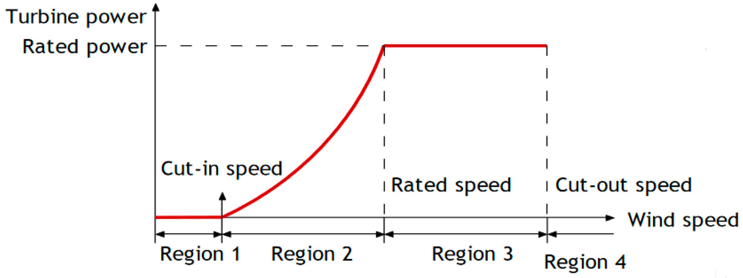
The wind turbine extracts kinetic energy from air flow via the blades. The conversion of air flow power to the main-shaft power is optimized via the optimization of the pitch angle controller, which keep the power generation at low and medium wind speeds (regions 2 and 3 in Figure 2), all of which are geared towards increasing the amount of captured energy. The power extracted from the air flow via the wind turbine blades can be calculated using the following expression:
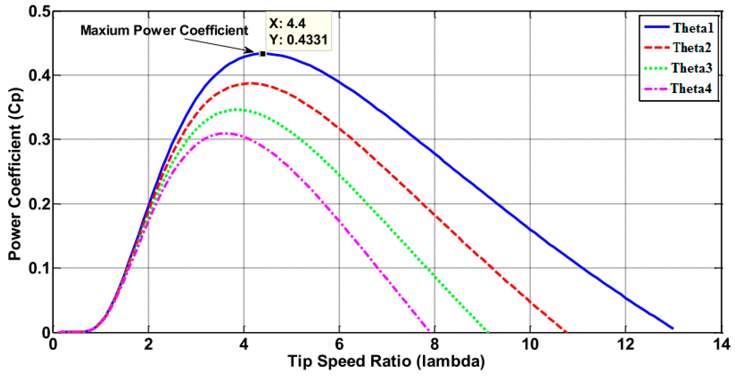
where Pm is the mechanical power extracted from the wind, ρ is the air density, R is the rotor radius, VW is the wind speed, and CP (λ, θ) is the aerodynamic power coefficient, which depends on the pitch angle θ and the tip speed ratio λ, resulting in:
where λ = Rωt/VW, Cf is the blade design constant coefficient and ωt is the rotational speed of the wind turbine. From Equation (1) it can be observed that the wind turbine achieves the maximum power production if the CP is maximum for a given pitch angle.
It can be seen in Figure 2 that the power curve is split into four distinct regions. Region 1: Standby mode, Region 2: Control to maximize power, Region 3: Control to rated power, and Region 4: Turbine shut down. As Region 2 consists of low wind speeds and is below the rated turbine power, its blades run at maximum efficiency to extract the maximum power. Region 3 is a transition region that is mainly concerned with keeping rotor torque and noise low.
In Region 2 (refer to Figure 2), the blade pitch angle is kept at it maximal conversion angle (near 0°) and the machine is kept at the peak of the CP vs. λ curve as shown in Figure 3 via generator torque control using measurements of the generator’s speed. In Region 3, the pitch angle is moved away from its maximal power conversion angle based on the measurement of power.
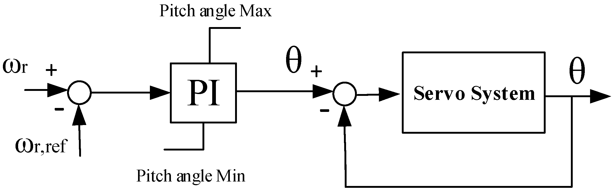
The pitch angle controller is shown in Figure 4 [23]. It usually consists of a proportional-integral (PI) controller and a servomechanism system. The pitch angle range and its corresponding rates of change are limited. Beyond the rated wind speed, the speed deviation can be regulated by this pitch angle controller to increase θ1 until it reaches its maximum limit of θ4.
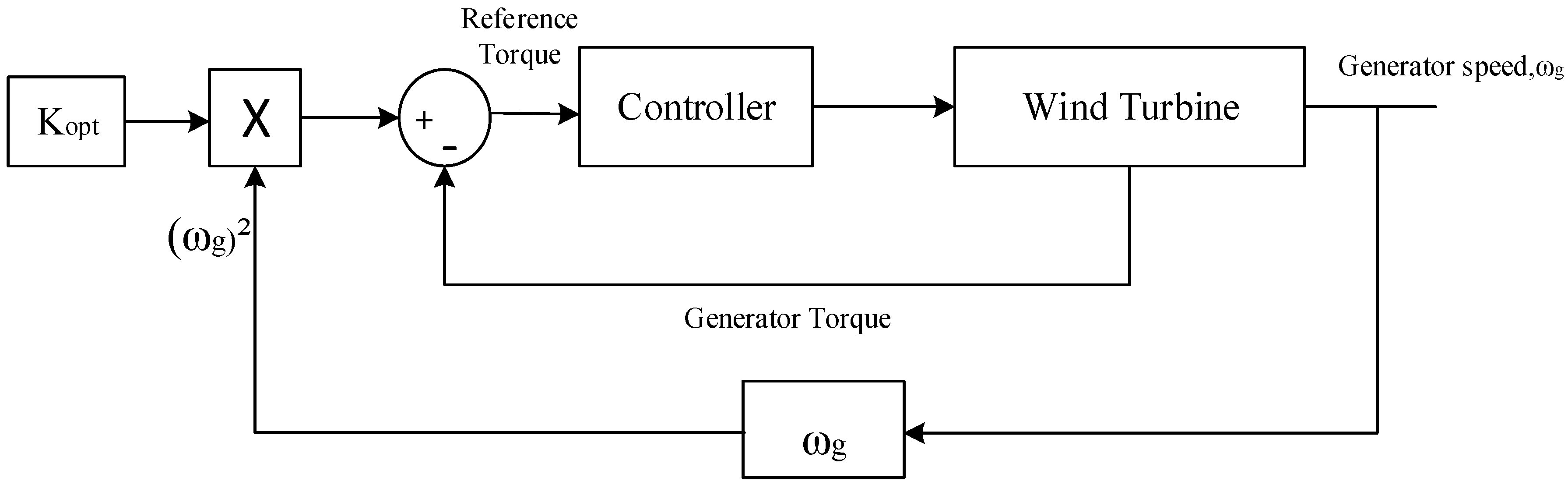
It should also be pointed out that there are other control techniques for wind turbines, such as torque gain control. The generator torque control is usually utilized in Region 2 [24]. At this state, the main objective is maximizing the power captured from the wind, and this is only possible if the torque generator is used optimally operate the turbine at a constant pitch angle of θ, as shown in Figure 5.
The torque control law is:
where the gain K is given by blade parameter:
The main features of the kω2 law is that it brings the turbine to its optimal point only using a rotor speed as illustrated in Figure 5. It also does not need wind speed information. Figure 6 shows the block diagram of the optimal torque control method.
For varying the speed of the wind turbine, the maximum aerodynamic efficiency is obtained by controlling the turbine’s rotational speed to keep the tip speed ratio constant at a predefined value that corresponds to the maximum power coefficient over the range of operational wind speeds [25].
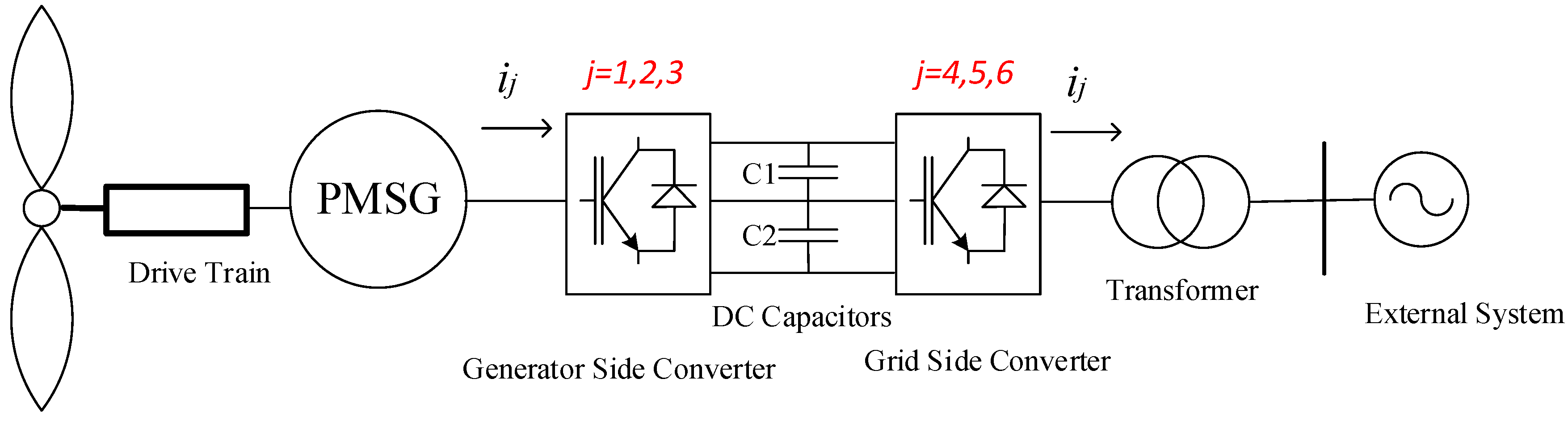
The typical structure of the WT-PMSG is shown in Figure 7. Three-phase stator winding of the generator is indirectly connected to the external power system via a full scale B2B VSC-based power converter. The generator side converter is connected with the stator of PMSG, while the grid side converter is connected to an external power system. DC capacitors are connected to both DC sides of two converters, which functions as the DC voltage resource for the AC/DC power transformation. The multi-pole generator and prime mover are directly driven by the shafts without the use of a gearbox [26,27].
PMSG converts the mechanical power from aerodynamic system to AC electrical power, which is then converted to DC power via an IGBT PWM converter connected with dc link. The power is transferred to the grid via another IGBT PWM inverter. The electrical model of the PMSG has been developed in [28,29]. The equivalent circuits of the PMSG in direct and quadrature axes are shown in Figure 8. The stator voltage equations in the d-q reference frame, and , are:
where Esd is the d-axis voltage on the stator-side of PMSG, Esq, is the q-axis voltage on the stator-side of PMSG, Isd is the d-axis current on the stator-side of PMSG, Isq is the q-axis current on the stator-side of PMSG, Rs is the resistance on the stator side of PMSG, Ls is the self-inductance on the stator side of PMSG, is the constant flux linkage of PMSG and ωe is the electrical rotational speed of the generator.
The electromagnetic torque, Te, is defined in [28,29] to be:
where Ld, Lq are the two-axis machine inductance and p is the number of pole pairs. In surface mounted PMSG, Ld = Lq = Ls, hence, the electromagnetic torque can be defined as follows:
The relation between angular frequency of the stator voltage, ωe, and mechanical angular velocity of the generator rotor, ωm, is [30]:
3.1.1. Model of Controller for Wind Turbine-Permanent Magnet Synchronous Generator
Power electronic converters are used to form voltage/current waveforms generated by the PMSG according to the grid’s demands. Due to the frequency and the output voltage of a PMSG relying on the wind speed, an AC/DC converter, generator side converter and a DC/AC converter (inverter), network side converter are all needed to connect the generator to the grid [31].
The B2B convertor is shown in Figure 6. This topology consists of two conventional PWM-VSCs, which enables bidirectional power flow with a number of IGBTs. In this topology, two converters can be separately controlled, which compensates for the unbalance of power between the generator and grid sides [32].
3.1.2. The Generator Side Voltage Source Converter-Controller
The generator side converter control is mainly used to control the wind turbine’s shaft speed in order to maximize the output power according to the maximum power curve shown in Figure 3. The generator speed control is typically accomplished through the generator side converter. Controlling the generator-side converter allows the generator to tune the rotational speed based on the incident wind variation. To understand the control concept, the equation of motion should be discussed. The motion equation for a typical generator is given as [33]:
where is the inertia of the whole system including the turbine and generator (kg·m2), while is the friction factor (N·m·s·rad−1). The mechanical rotational speed of PMSG rotor is defined by:
where ωt is the turbine rotational speed and Gr gear ratio (if existed). For a gearless PMSG based wind turbine Gr = 1. Based on (10), the generator’s rotational speed is governed by the electromagnetic torque, hence speed control is obtained by generator torque control. From (7), the electromagnetic torque can be directly controlled by q-axis current component, Isq, which means that the speed can be controlled by changing the q-axis current component. The d-axis current component Isd is set to zero to minimize the current flow for a given torque, which minimizes resistive losses [29]. The stator voltage components, Esd and Esq, synthesized by the generator side converter, can be used to control the generator’s current components; Isd and Isq, corresponding to Equations (5) and (6), respectively. The controller requires feedback(s) from the PMSG stator current components, Isq. The error between the measured and referenced components is the input of the PI controller [30]. The compensation terms shown in Equations (5) and (6) ensures stable and decoupled active and reactive power controls, as per Figure 9. The output voltage will then be the input of space vector modulation (SVM), which produces the switching signal that drives the generator side converter.
3.1.3. The Grid Side Voltage Source Converter-Controller
The grid side converter control stabilizes the dc link voltage at its nominal value. The selection of the DC link voltage (VDC) depends on the value of the L-L rms voltage at the grid side (Vg-LL). The relation is: VDC > 1.633 Vg-LL, as stated in [34]. In order to realize a transfer of active power generated by the PMSG to the grid, the capacitor voltage is varied during wind turbine operations [35]. The dynamic model of the grid connection, in the reference frame rotating synchronously with the grid voltage, is given as follows [29]:
where L and R are the grid inductance and resistance, respectively. and are the inverter voltage components. If the reference frame is oriented along the supply voltage, the grid vector voltage becomes:
It can be seen from above equations that we can control the active and reactive powers by changing the d and q-current components, respectively. Also in order to transfer all the active power generated by the wind turbine the dc-link voltage must remain constant [35], as per in the following constraint [36]:
Based on (17), if the two powers (the wind turbine power and the grid power) are equal, there will be no change in the dc-link voltage. The control strategy of the grid side converter (shown in Figure 9) contains two cascaded loops. The inner loop controls the grid currents, while the outer loop controls the dc-link voltage and reactive power. The current control loop could be used to deal with power quality issues. The harmonic compensation is inserted to the action of the current controllers in order to improve its functionality. The outer loops regulate the power flow of the system by controlling the active and reactive powers being delivered to the grid. This also makes it easy to obtain the unity power factor flow (zero reactive power exchange), unless the grid operators require different reactive power settings.
In this control strategy, the currents are represented in the dq synchronous rotating reference frame and controlled with standard PI controllers. This control transforms the grid voltages and currents from the abc to their respective equivalents in the dq reference frame. It should also be pointed out that the abc variables are transformed to the dc components (dq components), and thus offers much simpler and feasible controllability. The control structures developed in this work use PI controllers, since they perform well controlling dc variables [36]. It can be seen in Figure 10 that the outer loops control the dc voltage by taking the dc voltage reference of VDC,ref, while the error signal produce Igd reference to inner current control loop that controls active power. The second channel controls the reactive power by producing Igq reference to the inner current control loop. The reactive power is set equal to zero.
3.1.4. Multilevel Converter for Wind Turbine-Permanent Magnet Synchronous Generator
The multilevel converter is an AC-DC-AC converter, comprised of two parts: the first is the rectifier, which is connected to the PMSG and a capacitor bank via twelve unidirectional commanded IGBTs. The second part is the inverter, which is connected to a capacitor bank and a second order filter, which are both in turn connected to an electric network via the twelve unidirectional commanded IGBTs. The groups of four IGBTs, linked to the same phase constitute a leg k of the converter. The index i, with i , represents an IGBT in leg k. Similar to the two-level converter modeling the logic conduction state of an IGBT is represented by the pair (i, k) and indicated by Sik . The multilevel converter is shown in Figure 6 [37].
For the switching function of each IGBT, the switching variable γk is used to signify the state of the IGBT i in the leg k of the converter. The index k, with k , identifies the leg of the rectifier, while k represents the inverter. The switching variable of each leg k is given by [38]:
Which are constrained by the topological restrictions, defined by:
With the two upper IGBTs in each leg k (S1k and S2k) of the converters, it is associated with a switching variable Φ1k , while the two lower IGBTs (S3k and S4k) is associated with a switching variable Φ2k, respectively, as per:
The voltage vdc is the sum of the voltages vC1 and vC2 in the capacitor banks C1 and C2, respectively, modelled by the state equation:
The multilevel converter is modelled by Equations (18)–(21). The authors in [39,40] designed high power semiconductor devices in a 5 MW-class PMSG wind turbine. A suitable power electronic switches IGBT was selected, and the power losses were calculated to determine the efficiency of the convertors. It should be pointed out that certain issues need to be addressed when selecting the semiconductor switches in a full convertor wind turbine. An example of this is the electrical current limitations of the semiconductor switches (such as IGBTs) in conveying added real power from extracting the rotating-mass kinetic energy. This is also the case for grid voltage support implemented by the injection of reactive power.
3.2. Offshore Wind Farm Voltage Source Converter-High Voltage Direct Current
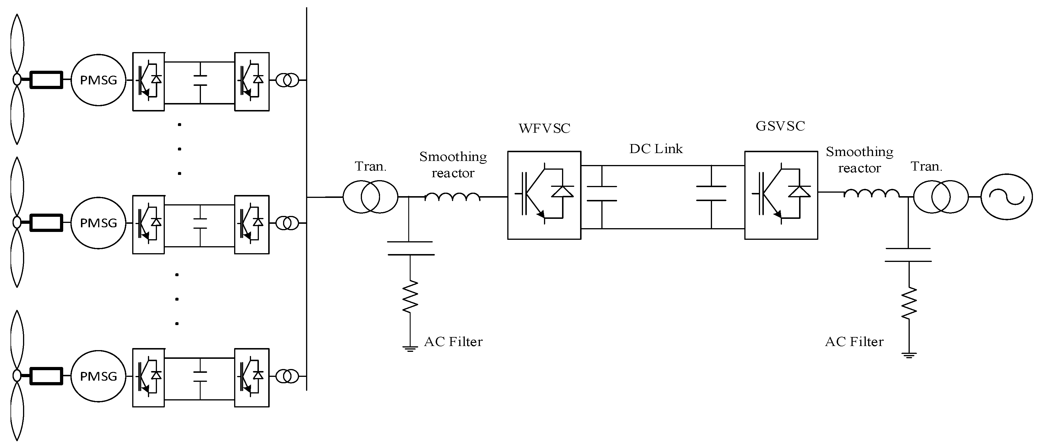
A schematic of a typical point-to-point VSC-HVDC system for grid integration offshore wind farm is illustrated in Figure 11. The offshore wind farm is composed of a group of WT-PMSG as a cluster. This structure manages wind energy and function like a conventional power plant. The load is not directly connected to the wind farm, but it is indirectly connected via the B2B HVDC system. Thus, the wind farm can operate at similar or different frequencies [41]. A VSC-HVDC uses a self-commutated switch such as IGBT with anti-parallel freewheeling diodes to convert the AC/DC power transformation. The DC capacitor on both sides aims to maintain the power balance between AC and DC powers and reduce the harmonics on the DC side. The coupling transformer and smoothing reactors and AC harmonic filters are connected to the AC bus on both sides and the DC cables [42].
The AC harmonic filter must be high passive filters to eliminate high order harmonics causing high-frequency PWM signal for switching IGBTs, whilst the smoothing reactors help control the active and reactive power flows by determining the current passing through them. Some of the advantages of VSC-HVDC include: independent control of active and reactive states using a PWM switching strategy capable of supporting the AC voltage network while dispatching active power by providing a lead and lag reactive power, and the ability to provide black start and fast frequency support to the AC network by modulating the active power.
3.2.1. Modeling of Voltage Source Converter
VSCs comes in the form of two models: a detailed model and averaged model. The former [43,44] includes all characteristics of semiconductor components with their switching action, while the latter requires clearing the topologies of the VSC, made up of two or multi-level. A detailed model is needed to analyze the PWM technique and study the VSC losses linked to the high-frequency harmonic component. Whilst the averaged model [45,46,47] does not consider the number of switching levels and the modulation technique. The averaged model is composed of the three-phase controllable voltage source connected to the AC side and the one controllable DC current source is connected to the DC side [46]. The averaged model of VSC is shown in Figure 12.
refer to the 3-phase voltage produced by VSC. refer to currents produced from the AC grid and going into the VSC. represents the injected DC current into DC grid from VSC, and is the shunt capacitor in the DC bus. Assuming that the balance power between the AC side and DC side and the converter power losses are negligible, the DC current in the DC grid can be calculated using:
It should be pointed out that the averaged model of the VSC takes much less time in a simulation compared to the detailed model of the VSC.
Figure 13 shows the single line representation of the VSC-HVDC transmission system. The left offshore-VCS works as a rectifier transforming the power from an AC offshore wind farm voltage to the DC link side, while the right onshore-VCS functions as an inverter, transforming the power from the DC link side to an AC onshore wind farm voltage for feeding.
3.2.2. Voltage Source Converter-High Voltage Direct Current Control System
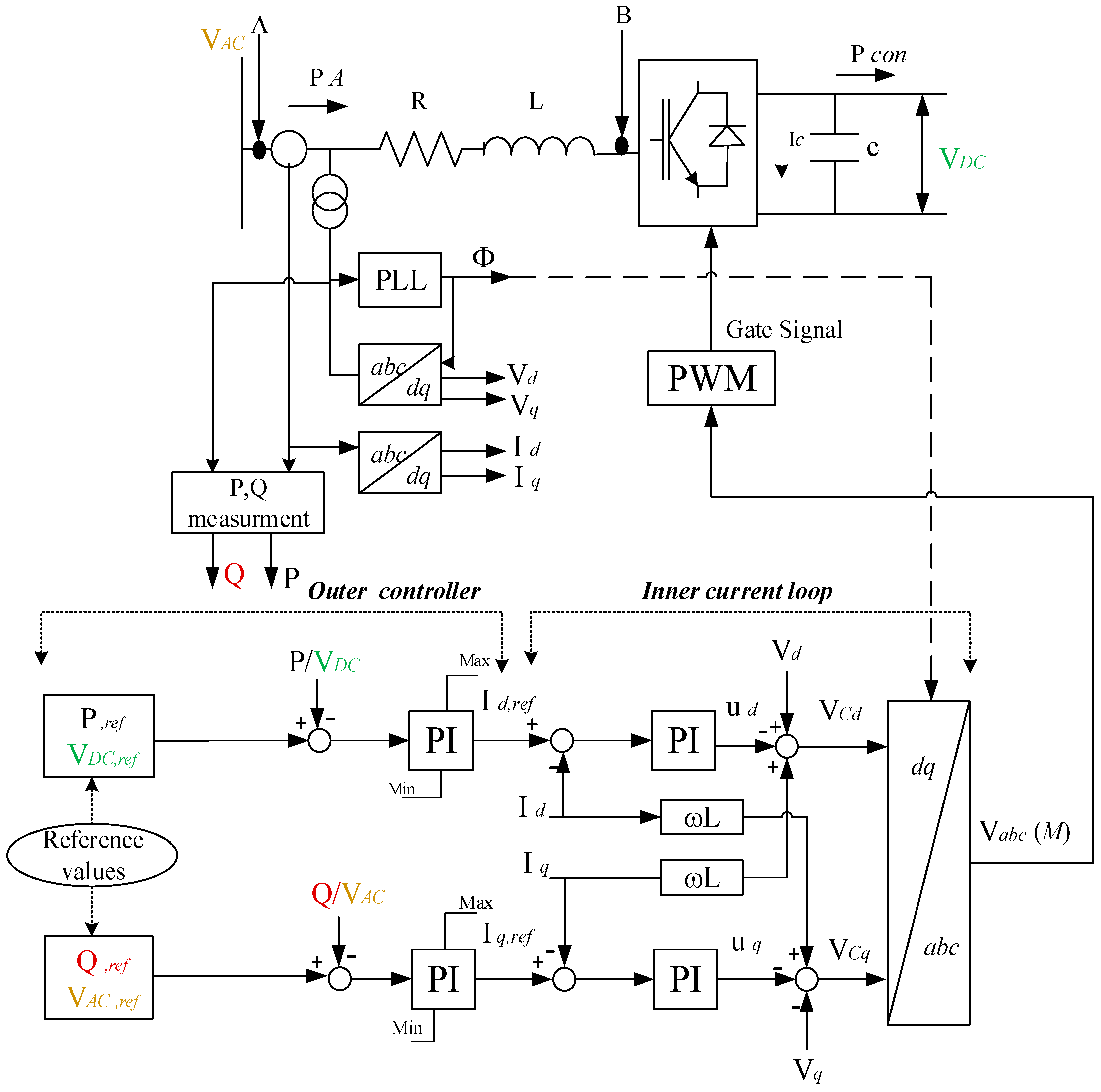
The main goals of the VSC-HVDC controllers are to keep the system stable and increase its performance. It can control one or more of the following variable: the active power, reactive power, AC voltage and DC link voltage. The VSC controller produces both parameters; modulation index (M) to generate the PWM modulation and phase angle (Ф). The M and Ф are modified by the vector control technique, while the d-q transformation references to the three-phase voltage and current rotating must be calculated to determine its exact contribution to the control system loops. There are two control loops: the inner loop controller that controls the current limitation to protect the VSC switches from the transient current caused from the disturbance current rating converter, and the outer loop controller, which creates a deviation between the controlled variable from the system and its desired value to generate the reference values for the inner loop controller. The phase-lock loop (PLL) is usually used to calculate the rotating phase angle (Ф) for an inner current loop [48]. Figure 14 shows the block diagram of the VSC-HVDC system.
As pointed out previously, the power injection into the VSC system can be calculated using:
where are the d-axis component of the voltage and current at point A respectively. From the power balance between the power input and output of VSC-HVDC system, the current flowing into DC capacitor () can be defined as:
The differential equation for the DC voltage can be defined as:
From Equations (28) and (29), it can be seen that the active power and DC bus voltage line can be regulated by the d-axis component of current (), as shown in Figure 12. The output of the active power and DC bus voltage controllers forms the reference of the d-axis component of the current. This output will be the input of the inner current loop. The d-axis current component reference must be limited so that it can limit the current in the VSC switches.
The reactive power controller relies on the q-axis component of current () to regulate reactive power, as per the equation:
Since the magnitude of the total current converter should be in the range of the rated current, the q-axis component of the current should be limited. The magnitude of the total current converter can be calculated using:
where , are the reference input for active and reactive current controller of the inner current loop shown in Figure 12, respectively.
The AC voltage () regulation is related to the reactive power via the q-axis component of current ().
By applying Kirchhoff’s voltage law between points A and B in Figure 12, we get:
It can be observed that only the reactive power parameter is used to control the AC voltage. The active power is controlled separately as detailed in Section 3.2.2.
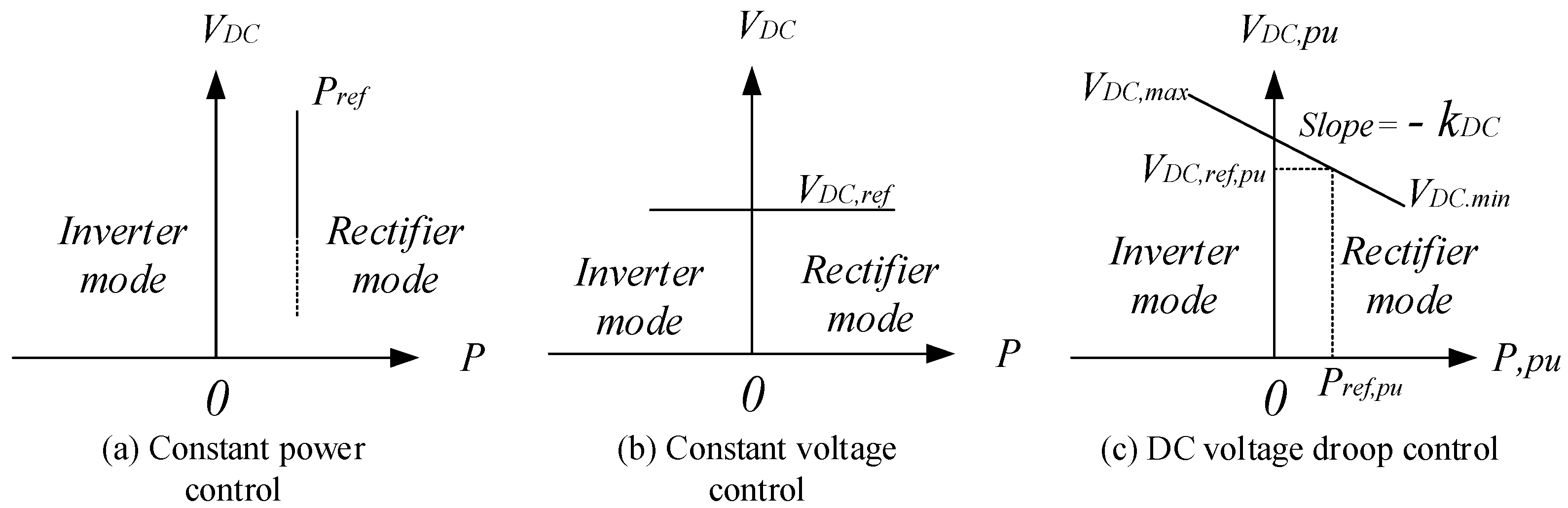
The VSC-HVDC controller should generate the reference active power after determining the type of outer controller. Generally, there is a three-mode outer controller; constant power controller, constant DC controller and DC voltage droop control. In the constant power controller, the direction of power flow depends on the value of the power reference, thus there is a rectifier and inverter operation mode. The level of the DC voltage at constant power controller is not considered in this case. Meanwhile, the constant DC voltage controller aims to maintain the DC voltage corresponding to its reference value.
The DC voltage droop control can utilize the P or PI controller to give a power droop characteristic with respect to the DC bus voltage. The power flow is positive for the rectifier mode and negative for inverter mode, as shown in Figure 15 [48]. The DC voltage droop constant () refers to the slope of active power versus DC voltage, while the value of DC voltage droop constant () represents how many unit droops in the DC voltage needs to increase in the active power unit.
Figure 15c illustrates that the VSC regulates VDC, ref, pu around a set value by balancing Pref, pu within a rated power capacity of the VSC-HVDC terminal. The DC voltage droop control can balance the total power between converter stations without any communication. The control strategy in the frequency droop control is similar to the DC voltage droop control, but the main goal of the frequency droop control for a VSC-HVDC connected to an offshore wind farm is to contribute to the primary frequency response on the main AC’s grid side.
3.3. Control Frequency Response Supported by Offshore Wind Farm and Voltage Source Converter-High Voltage Direct Current System
Due to the increasing level of offshore wind farm penetration into the grid (could be hundreds of MW), the main objective of an offshore wind farm is not only to dispatch active power to the AC grid, but to also offer a provision of voltage control ancillary and frequency regulation in a manner similar to a conventional power plant.
In an electrical power system, frequency stability refers to the ability of the whole system to keep the frequency within its nominal value. The frequency becomes unstable when there is an imbalance between power generation and power demand. The kinetic energy in the synchronous generator is stored in the rotating masses. After the sudden loss of generator units or increase in power demand, these energies will be released to achieve a new steady state in the power balance. The inertia response tries to slow down the initial rate of change of the frequency (ROCOF) using different methods. This process is described via Equations (29) and (30):
where H is the inertia constant in seconds, ω is the machine nominal speed of rotation in rad/s, is the moment inertia of the rotating mass in kgm2, SRATED is the rated power of the machine, df/dt is the ROCOF, and ΔP is the amount of power change in system demand (e.g., as a result of increase/decrease load, loss of a generator, etc.). When the grid frequency drops to a value that is lower than 0.5 Hz from 50 Hz, the generator should increase its power by the amount of the primary response within 10 s and continue to generate extra output power for a further 20 s, this is the primary response. The secondary response is activated to restore the frequency to its normal operating range. This action needs to maintain power output from 30 s up to 30 min [49]. Figure 16 illustrates the natural frequency response. The primary frequency response aims to stop the excursion and reach a steady state, whereas the secondary frequency response exerts the efforts to restore the frequency to its nominal value via automatic generation control (AGC).
Referring to Figure 16, the synchronous generator provides a primary frequency response within 30 s. The rotational kinetic energy in variable speed wind turbine generators is used to realize a short-term frequency support in [50,51,52,53,54]. To solve deviations in the frequency system, a control strategy is proposed to provide an inertia response for the wind turbine by adding a control loop to the frequency deviation derivative, which provides an extra active power production. In Figure 17, the additional ΔPref in the controller of rotor side convertor is the result of the inertia control loop [55]. Thus, when frequency fluctuations occur, the inertia control loop produces ΔPref to change the variable speed wind turbine active power reference Pref. Consequently, the output active power changes according to the frequency deviation in a short time [56].
The authors in [56] presented a new controller designed for a nonlinear model of a variable-speed wind generator connected to the AC mainland grid via a full-scale power and frequency converter. The structure of the converter controller is applied by the duty- ratio input signals to the converters. The proposed controller is able to multi-task based on guess works such as maximum power point tracking (MPPT) and power factor controller (PFC), and there is no limit to the duty ratio within the acceptable range of the converter parameters’. The main goal is to realize accurate stability of the dynamic models for whole system parts (converter, generator, DC link) via the new controller design approach.
Wind turbine generators use power electronic interfaces and HVDC links, which causes decoupling in the available kinetic energy with prime movers in an offshore farm from the AC grid. Thus, the uncontrollable variable speed wind turbine with VSC-HVDC transmission, which is a commonly used component in wind farms decrease the total inertia response in the AC power system. Researchers have proposed multiple solutions for this problem the main idea of which is mostly based on storing the active power and then releasing it in the event of frequency deviations in the AC grid. In other words, the offshore wind farm is not generating all of the active power capabilities, thus the difference in the active power between the actual generation and its available capability is a reserve margin active power (). This injected reserve margin will depend on sensing a ROCOF in the AC grid. The final process is called a de-loading operation. [57,58,59] presented a de-loading operation using the control of the wind turbine generator and/or pitch angle control to provide a support frequency.
The wind turbine can increase the power extracted from the wind by regulating the aerodynamic torque (or power) [60], leading to the so-called optimal power- rotational speed curve. The optimal aerodynamic power is computed by:
where is the speed of the turbine and is the optimal aerodynamic torque coefficient which relies on the aerodynamics of the turbine and the pitch angle . Usually, the (P-ωm) curve is implemented in a look-up table in the controller of the machine side power converter of the wind turbine, leading to the so-called maximum power tracking algorithm (MPT). In order to generate maximum power in the partial-load operation, the pitch angle should be kept constant at zero degrees. The pitch angle controller is activated and the generated torque is kept constant, which keeps the power collected from the wind in check (i.e., not exceeding its rated power) [61,62,63,64]. The pitch angle is changed to mitigate the turbine mechanical loads as per Figure 18.
Usually, a PI controller is used to regulate the pitch angle by determining the difference between the rated power reference of the turbine and the actual output power feedback. Due to a grid’s frequency fluctuations, the wind power plant should participate in primary control by increasing/decreasing its output power based on the power—frequency droop characteristic at designated time. A de-loading method is supposed to solve the aforementioned problem. The method can be realized in two ways: speed control and pitch control [17].
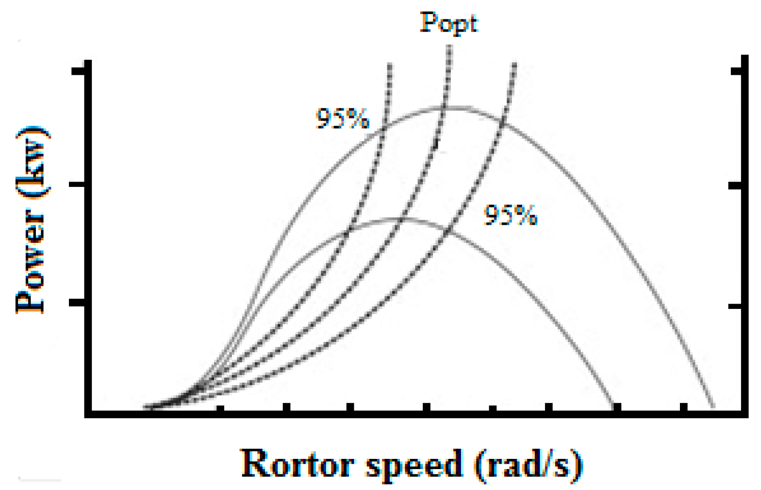
A speed control method operates the wind turbine at non-optimal working point in the power rotational speed (P-ω) curve by increasing/decreasing the rotor speed (over-speeding or under-speeding) at a pre-set power, by keeping the pitch angle constant. The wind turbine is forced to generate less active power than its optimum value by increasing the rotor speed to offer a reserved active power. When the frequency dropped as a result of a sudden load increase or loses a large supply of generators, a reserved active power is injected into the AC grid. Contrarily, the decrease in the rotor speed reduces in the output power, but leads to an increase in active power production transiently since the rotor releases kinetic energy in this situation. The main drawbacks of the under-speeding de-load method is that when the rotor speed increases, the active power will be consumed by the generator for acceleration and it will take a long time for it to be restored to its original speed. This could also lead to small signal stability. Consequently, the increasing rotor speed is preferred. Figure 19 illustrates a 95% de-loaded active power curves of the maximum available power curve.
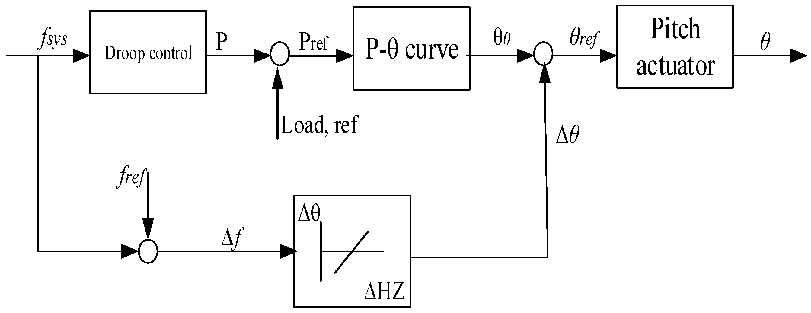
As pointed out previously, a pitching control is another de-loaded method. The principle of the operation of this method is based on decreasing the pitch angle to limit the active power production to a value lower than its nominal value by keeping the rotational speed constant. When the system frequency decreases, the pitch angle is regulated as the difference between the frequency reference and the actual frequency measurement. Figure 20 depicts the schematic pitch controller, which includes the primary frequency control droop.
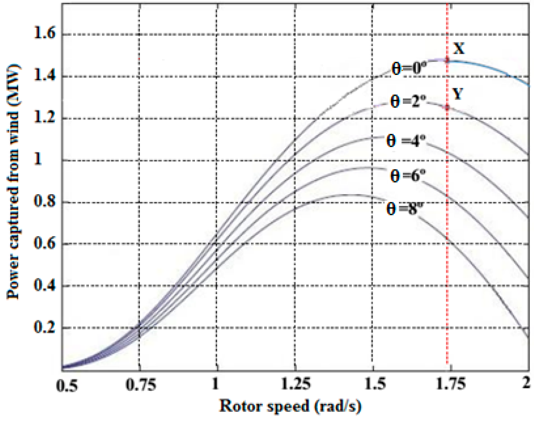
Figure 21 shows the application of pitching control and increasing speed rotor, de-load techniques at the (P-ω) curve. It can be seen that the point (X) is the maximum power operating point. When applying pitch control, the operating point moves from (X) to (Y) at similar rotor speeds whilst the operating point moves from (X) to (Y) after applying the over-speeding de-load technique by maintaining the same pitch angle. It should be pointed out that over-speeding could only be applied to variable speed wind turbines such as full-converters-based wind turbines. Table 2 shows suitable de-loading techniques based on the range of the level speed.
Researchers have reported many control strategies utilizing wind turbines for primary frequency regulation. The authors proposed the usage of the pitch angle control to maintain a power reserve by activating the controller when the wind generator works close to the rated power. In [65], the authors proposed a de-loaded maximum power curve strategy in the doubly fed induction wind generators to regulate the system’s frequency. This control strategy is based on an increase/decrease of the active power and rotor speed in order to realize the de-loaded optimum power curve based on the system’s frequency changes. A combination of adding a control loop by acting on the rate of change of frequency with acting on the frequency deviation and de-loading technique in the WT-DFIG to enhance inertia response and power reserve, respectively, provides an avenue for primary frequency regulation [66].
In [67], the authors proposed two de-loading techniques: over-speeding and pitch-controlled de-loading. In the low-level wind speed, the over-speeding method is applied by setting the reference value of active power in the rotor side convertor controller, based on the de-load optimum power curve with rotor speed measurements at a zero pitch angle. In this state, the wind measurements are not required. In the high power speed wind region, the extracted active power can be determined by activating the pitch angle controller, which is based on the margin de-load optimum power curve and the actual pitch angle feedback measurements. It should be pointed out that different two techniques of de-loading methods do not work simultaneously. The optimum power curve is obtained from the wind speed measurements. The pitch control and control of the static converters are used to adjust the rotor speed to its optimum value for the required optimum power operation. The measurement wind speed is inaccurate and reliable due to the influences of the rotor effects in the real value of the wind speed [68]. The authors suggested using a combination of rotor speed control and pitch angle control in the low rated rotor speed region simultaneously [69].
The distance between the offshore wind farm and the onshore grid via VSC-HVDC transmission system causes a communication delay for the transfer of measured frequency of the AC grid. As a result of this, the frequency regulation response in the offshore wind farm is slow and is unable to provide it with an appropriate quantity of active power to the rectifier-VSC. Various approaches have been proposed in [46,69,70,71,72] to address this problem.
In [72], a supplementary control loop was used in the inverter-VSC to produce a control signal, which was then sent to offshore wind farm via a communication channel. This signal represents the state of the AC grid frequency deviation to activate or de-active the de-loading control system to support the AC grid’s frequency.
In [65,70], a communication less in an AC onshore frequency regulation approach was investigated. The system used a DC link voltage of VSC-HVDC to indicate the variation of the AC grid’s frequency onshore. This technique also supports frequency regulation by implementing a frequency-voltage droop control on the inverter-VSC. The authors in [73] proposed the inertia emulation control strategy to provide a primary frequency. The stored energy in a DC capacitor is released using the voltage controller in the inverter-VSC.
The authors in [41] used an additional fixed capacitance in VSC-HVDC system in order to provide a support frequency regulation by emulating an inertia constant (H). The proposed method depends on variations in the DC voltage bus, but the maximum permissible limit of DC bus voltage variation must also be accounted for. The performance of this method was validated using the AC fault systems, and sudden load changes resulted in a positive effect of emulating a wide range of inertia constant, which improved the frequency response.
The control strategy proposed in [73] relies on the coordination between the DFIG, DC link voltage, and the two converters on both sides of the VSC-HVDC system. To improve the inertia of the power system, the electrical energy is released or absorbed in the DC link voltage using a droop control on the grid side converter according to the changes in the onshore frequency. A measured, controlled DC link voltage on the wind farm side is used in the variable frequency control in the offshore wind farm. This provides a tenuous link between the onshore frequency and offshore frequency that lack direct communication signals. As a result of the change in the offshore grid frequency, the wind farm should regulate its active power production by altering its active power reference to enhance the frequency response in the onshore grid frequency. Consequently, the DFIG varies its rotor speed to provide the inertia response. The proposed control strategy was proven to be effective via three tests: wind speed variation, AC system faults and variable loads. In short, this control strategy enhances the inertia system support with a small time delay.
4. Discussion
This paper details the modeling of two-terminal VSC-HVDC via multiple control strategies aiming to achieve a stable steady state of power flow from an offshore station to an AC grid. The converter on the offshore side operates in the rectifier mode, while the converter on the AC grid side operates in the inverter mode. As pointed out previously, each converter has three-control modes; constant power control, constant dc voltage control, and dc voltage droop control. When both converters use the same controllers, namely power constant and dc voltage constant, it will not be able to achieve stability in steady state operations, making these configurations inapplicable. Contrarily, when using the dc voltage droop control on both sides of the converters, the results remained stable in the steady state operation without experiencing the dc over-voltage problem. However, this configuration is ineffective for determining the power and dc voltage references in an accurate and frequent manner in order to obtain the desired power flow. The other control configurations in the VSC-HVDC system that cause the dc over-voltage problem are constant power control on the rectifier side with one of the other control modes on inverter side, and the dc droop in the inverter or constant dc voltage. The dc over-voltage problem occurs when the converter on the AC grid side cannot receive power from the dc circuit by continuously dispatching a power from the converter on the offshore side to the dc circuit. The inverter’s inability to receive power is caused by the AC fault taking place in the AC grid or by opening the dc link that connects the rectifier and inverter stations. To avoid the dc over-voltage problem in the dc link, the dc voltage control is applied on the rectifier side of VSC-HVDC system. The rest of the configuration control modes performed well, since the power is controlled in one of two stations, while the other compensated the increasing/decreasing power in the dc link circuit. Table 3 summarizes the various control configurations for VSC-HVDC.
The HVDC system is capable of fully controlling the power flow at any voltage and frequency at the reception point. The control methods for providing a frequency response in an offshore wind system can be classified as contributions to the primary frequency control via WT-PMSG/DFIG and VSC-HVDC transmission systems. For the wind turbine level, first, in order to meet the inertia response in DFIG, the extra active power should be injected into the system, and to achieve this, the addition of a control loop on the rotor side generator generates a new reference power, which is defined when rate of change frequency (ROCF) takes place. The extra power is dispatched from the kinetic energy is stored in the rotating blades of the wind turbine. The de-loading operation is the second method in the WT-PMSG, where the wind turbine works at a different power-rotational speed from the optimum curve by using a pitch angle controller. A power reserve is extracted when the frequency drops. Table 4 summarizes the frequency regulation strategies in the grid integrated offshore wind turbines via VSC-HVDC technology with some performance related issues.
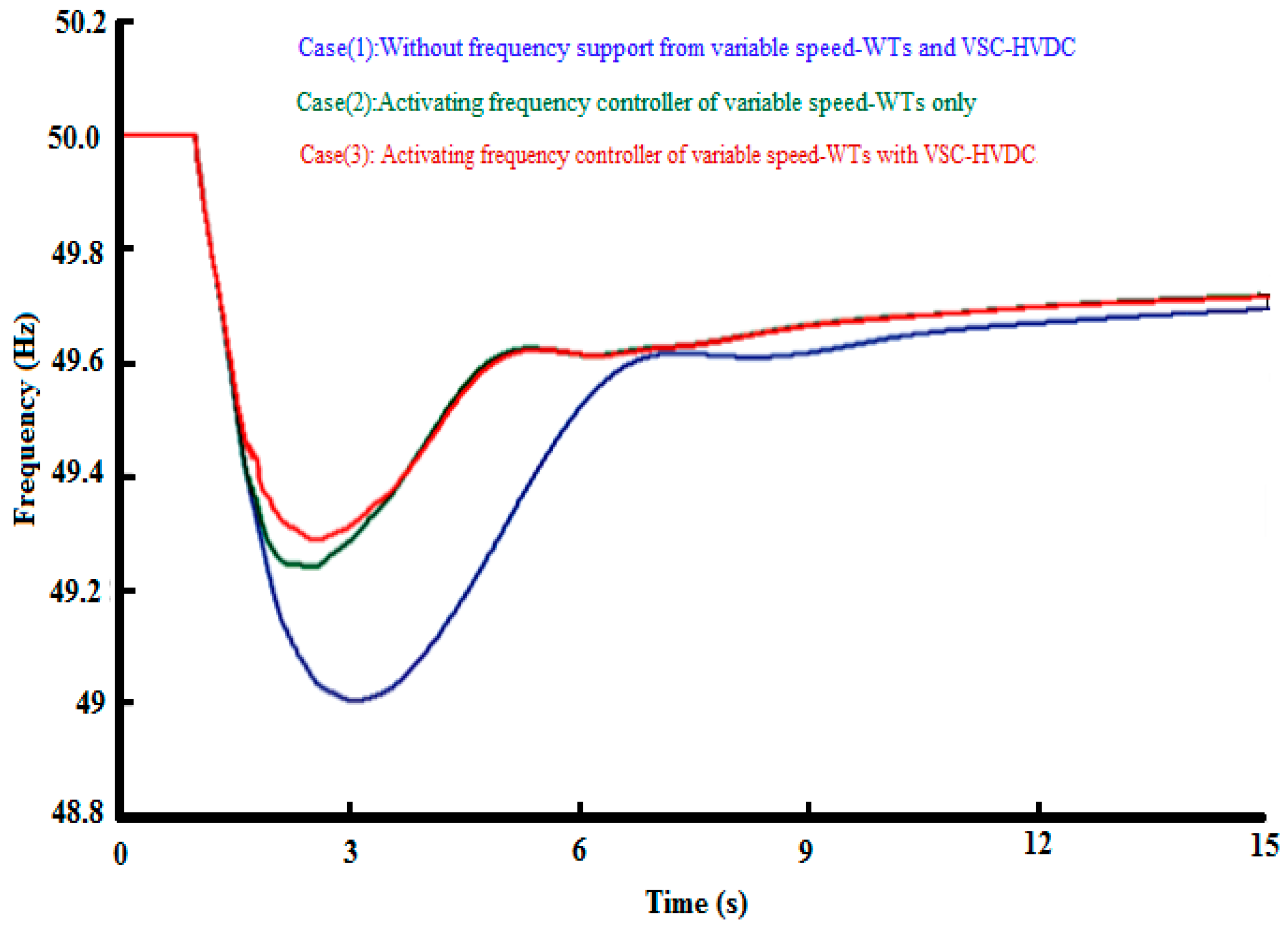
From the frequency response of the VSC-HVDC, as per the literature, it can be seen that the VSC-HVDC transmission contributes to the systems’ frequency regulation. We intend to highlight the effectiveness of different frequency responses to sudden increase in load in three cases: without frequency support from variable speed-WTs and VSC-HVDC, activating frequency controller of variable speed-WTs only, and activating frequency controller of variable speed-WTs with VSC-HVDC. It is obvious that the frequency support from an offshore wind farm provides active power for increasing load while significantly minimizing the frequency drop. The frequency can stabilize faster without frequency support from variable speed-WTs. Furthermore, due to the participation of the VSC-HVDC in frequency support with variable speed-WTs, the nadir frequency is improved. The coordinated control of a wind farm and VSC-HVDC system also provide frequency support [75]. Figure 22 shows the different frequency response present in the three aforementioned cases.
When the frequency controller of variable speed-WTs detects the frequency drop, the controller is activated immediately. As a result of activated frequency regulation, the active power of variable speed-WTs increases instantly while both WT-generator with pitch angle decreased. Figure 23 illustrates the frequency regulation in the three cases for speed of wind turbine generator, pitch angle and offshore active power production Figure 23a–c shows the co-operation of supplementary frequency controller in variable speed-WTs and pitch controller leading to fluctuation in the speed generator. The effect VSC-HVDC frequency controller on the operation of the offshore wind turbine remains unclear [75].
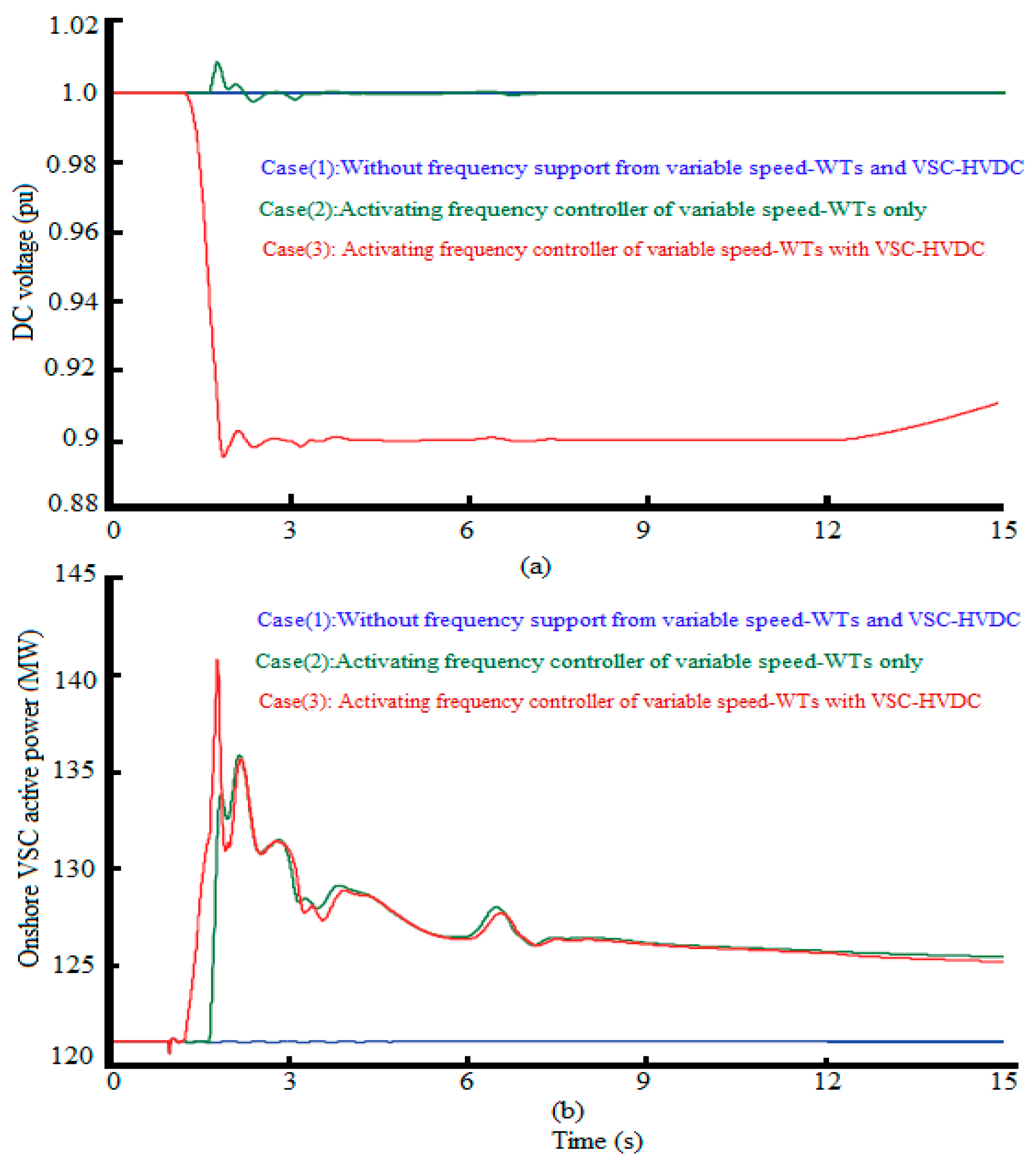
Figure 24 shows the VSC-HVDC response for increasing loads When the control frequency regulation in VSC-HVDC is activated, the DC voltage level of the DC link rapidly decreases to 0.9 pu to release the power stored in the DC capacitors to the AC grid via onshore VSC. However, the DC voltage fluctuates within a certain range, so the amount of energy released/absorbed by the DC capacitor is limited. Therefore, the frequency support is only viable for a short amount of time [75]. Figure 24b shows the active power output from the onshore VSC. It is clear that the active power is increased to support the grid’s frequency. As a consequence of this, blending offshore wind turbine with VSC-HVDC frequency regulations results in an effective frequency response.
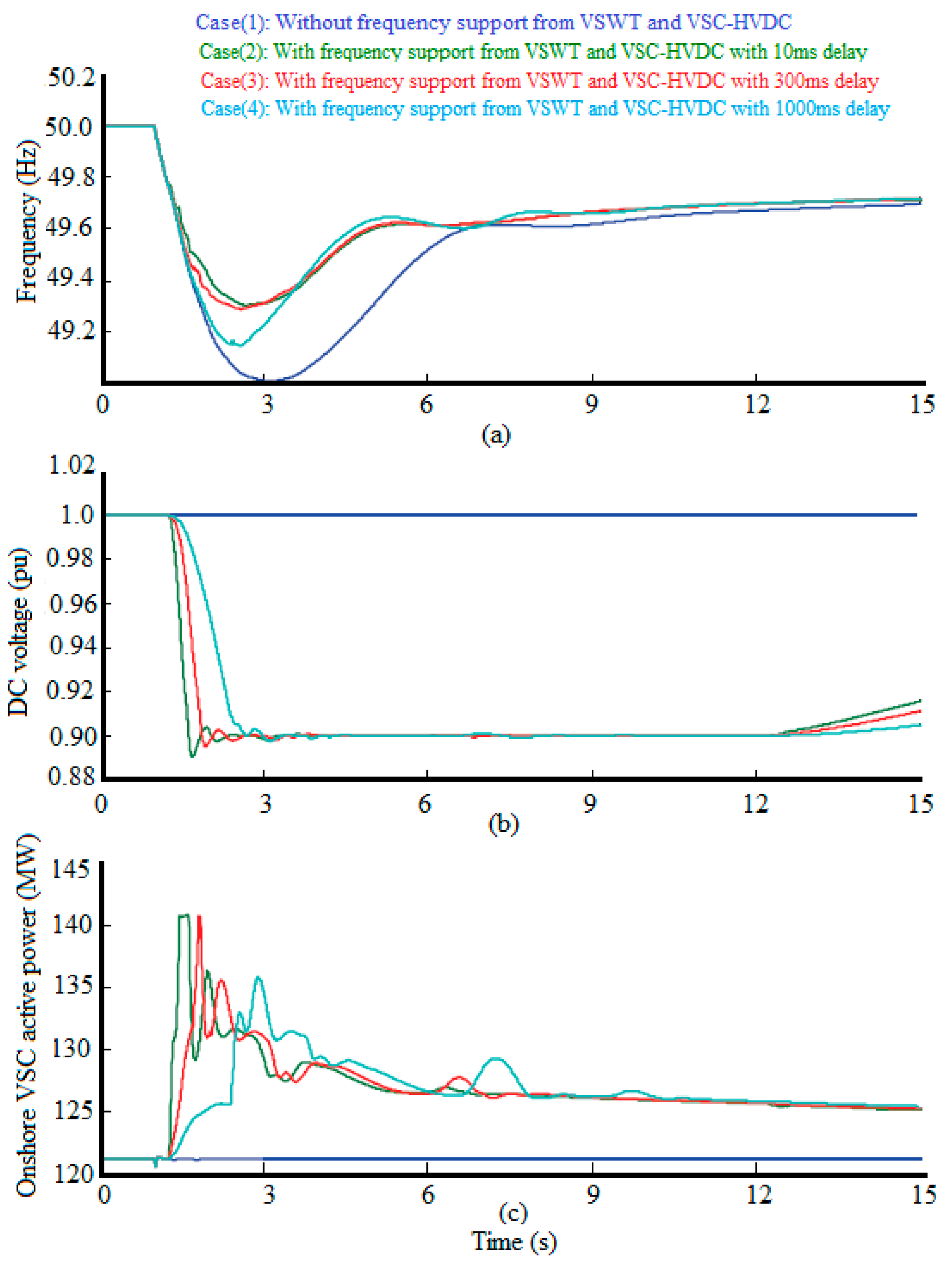
In a coordinated control wind turbine and VSC-HVDC system, a remote communication or communication-less system, as mentioned previously, could be used to detect the frequency deviation in the AC grid. The communication choice reports a communication delay due to the type of communication and the distance between the AC grid and VSC offshore wind turbine. The communication delay of the VSC-HVDC system affects the system’s frequency response, and is linked to long periods of time delay. Figure 25a demonstrates the influence of communication delay time for an unexpected increasing load. With increasing communication delay time, the nadir frequency decreases significantly alongside the rate of change of frequency. Nevertheless, for all the different communication delay times, almost all share the same final value frequency steady state. The effect of communication delay time on the DC link voltage is shown in Figure 25b. For a longer communication delay time, the slope decline of the DC link voltage is less steep. This means that the stored the power in the DC capacitor require more time to release its stored power and inject it into VSC inshore to the AC grid in order to regulate the system’s frequency. A second frequency drop will take place when the DC capacitor stop releasing power and the power dispatched offshore is unable to increase its generated power. To avert a second frequency decrease, a longer communication delay time should be used to allow enough time for the DC capacitor to continue discharging with dispatch power to AC grid simultaneously. Thus, the communication delay time of VSC-HVDC has a temperate DC voltage change, and does not provide a minimum nadir frequency response. However, it offers a softer and longer power release of the DC capacitors simultaneously in order to provide better system frequency support.
5. Conclusions and Recommendations
This paper detailed the dynamic models for the PMSG and HVDC systems. The different control methods used to deal with problems associated with frequency system deviation that were caused by a sudden imbalance and inertial response limits of the wind turbine-HVDC system during the first seconds have also been highlighted. The dynamic model of the PMSG is commonly used in wind farms to cope with a vector controller to decouple dynamically active and reactive power controls. The control methods for providing a frequency response in offshore wind system can be regarded as a contribution to the primary frequency control via WT-PMSG and VSC-HVDC transmission systems. Variable speed wind turbines such as WT-PMSG cannot use its inertia response due to the decoupling by power electronic devices from the AC grid. Therefore, the offshore wind farm has the capability to regulate the frequency via reserve power by utilizing an HVDC transmission in two ways: first by using a remote communication to send the activated control signal to the WF-VSC, or send the frequency deviation value in onshore AC grid in order to adopt the active power in the WF-VSC. The second is a communication-less approach, where a transfer frequency deviation between onshore and offshore was used based on the frequency- DC voltage droop control. The communication-less approach is more viable since it does not require infrastructure communication station, which translates into lower investment costs. On the other hand, the emulation inertia response can be provided in the VSC-HVDC system by storing/releasing the electrical energy in the DC shunt capacitors depending on the reference DC voltage value in the GS-VSC controller. To improve the efficient inertia level of power systems, the coordinated control strategy of the variable speed wind turbine and the VSC-HVDC system, a combination of kinetic energy stored in the rotor with energy storage units in HVDC system is utilized. It is necessary to investigate the control of primary frequency response in Multi Terminal Direct Current (MTDC) grid to increase the penetration level of the offshore system with conservatism in the AC grid stability limit.
Acknowledgments
This research is funded by University of Malaya under Postgraduate Research Grant (PPP): PG323-2016A.
Author Contributions
Jafar Jallad, Saad Mekhilef and Hazlie Mokhlis collected information; Jafar Jallad wrote the paper and improved it further with the feedback from Saad Mekhilef and Hazlie Mokhlis.
Conflicts of Interest
The authors declare no conflict of interest.
References
- Saidur, R.; Rahim, N.; Islam, M.; Solangi, K. Environmental impact of wind energy. Renew. Sustain. Energy Rev. 2011, 15, 2423–2430. [Google Scholar] [CrossRef]
- Saidur, R.; Islam, M.; Rahim, N.; Solangi, K. A review on global wind energy policy. Renew. Sustain. Energy Rev. 2010, 14, 1744–1762. [Google Scholar] [CrossRef]
- Anaya-Lara, O.; Campos-Gaona, D.; Moreno-Goytia, E.; Adam, G. Offshore Wind Energy Generation: Control, Protection, and Integration to Electrical Systems; John Wiley & Sons: Hoboken, NJ, USA, 2014. [Google Scholar]
- Sawyer, S.; Rave, K.; Global Wind Energy Council. Global Wind Report Annual Market Update. GWEC. Available online: http://www.Gwec.Net/wp-content/uploads/2015/03/gwec_global_wind_2014_report_lr.Pdf (accessed on 1 May 2015).
- The European Wind Energy Association (EWEA). Eastern Winds Emerging European Wind Power Markets. Available online: http://www.Ewea.Org/fileadmin/files/library/publications/reports/eastern_winds_emerging_markets.Pdf (accessed on 12 September 2014).
- Agency, I.E. World Energy Outlook 2012, Renewable Energy Outlook 2012. Available online: http://www.Iea.Org/publications/freepublications/publication/weo2012_free.Pdf (accessed on 22 September 2014).
- Wu, F.; Zhang, X.-P.; Godfrey, K.; Ju, P. Modeling and control of wind turbine with doubly fed induction generator. In Proceedings of the PSCE’06 2006 IEEE PES Power Systems Conference and Exposition, Atlanta, GA, USA, 29 October–1 November 2006. [Google Scholar]
- Strachan, N.P.; Jovcic, D. Stability of a variable-speed permanent magnet wind generator with weak ac grids. IEEE Trans. Power Deliv. 2010, 25, 2779–2788. [Google Scholar] [CrossRef]
- Ahsanullah, K.; Dutta, R.; Rahman, M. Review of pm generator designs for direct-drive wind turbines. In Proceedings of the 2012 22nd Australasian Universities Power Engineering Conference (AUPEC), Bali, Indonesia, 26–29 September 2012; pp. 1–6. [Google Scholar]
- Liserre, M.; Cardenas, R.; Molinas, M.; Rodriguez, J. Overview of multi-mw wind turbines and wind parks. IEEE Trans. Ind. Electron. 2011, 58, 1081–1095. [Google Scholar] [CrossRef]
- Halder, T. Comparative study of HVDC and HVAC for a bulk power transmission. In Proceedings of the 2013 International Conference on Power, Energy and Control (ICPEC), Dindigul, India, 6–8 February 2013; pp. 139–144. [Google Scholar]
- Silva, B.; Moreira, C.; Seca, L.; Phulpin, Y.; Lopes, J. Provision of inertial and primary frequency control services using offshore multiterminal hvdc networks. IEEE Trans. Sustain. Energy 2012, 3, 800–808. [Google Scholar] [CrossRef]
- Perveen, R.; Kishor, N.; Mohanty, S.R. Off-shore wind farm development: Present status and challenges. Renew. Sustain. Energy Rev. 2014, 29, 780–792. [Google Scholar] [CrossRef]
- Quitmann, E.; Erdmann, E. Power system needs–how grid codes should look ahead. IET Renew. Power Gener. 2014, 9, 3–9. [Google Scholar] [CrossRef]
- Brown, R.E. Distribution reliability assessment and reconfiguration optimization. In Proceedings of the 2001 IEEE/PES Transmission and Distribution Conference and Exposition, Atlanta, GA, USA, 2 November 2001; pp. 994–999. [Google Scholar]
- Tielens, P.; Van Hertem, D. The relevance of inertia in power systems. Renew. Sustain. Energy Rev. 2016, 55, 999–1009. [Google Scholar] [CrossRef]
- Yingcheng, X.; Nengling, T. Review of contribution to frequency control through variable speed wind turbine. Renew. Energy 2011, 36, 1671–1677. [Google Scholar] [CrossRef]
- SIEMENS. Turbina Sapiens a Different Breed of Wind Turbine. Siemens 6.0 MW Offshore Wind Turbine. Available online: http://www.Energy.Siemens.Com/mx/pool/hq/power-generation/renewables/wind-power/6_mw_brochure_jan.2012.Pdf (accessed on 2 May 2014).
- Sugimoto, H.; Goto, M.; Wu, K.; Yokomizu, Y.; Matsumura, T. Comparative studies of subsynchronous resonance damping schemes. In Proceedings of the International Conference on Power System Technology, Kunming, China, 13–17 October 2002; pp. 1472–1476. [Google Scholar]
- Snitchler, G.; Gamble, B.; King, C.; Winn, P. 10 mw class superconductor wind turbine generators. IEEE Trans. Appl. Supercond. 2011, 21, 1089–1092. [Google Scholar] [CrossRef]
- Arántegui, R.L. Technology, Market and Economic Aspects of Wind Energy in Europe, European Commission JRC Scientific and Policy Report; JRC Wind Status Report; Publications Office of the European Union: Luxembourg, 2013. [Google Scholar]
- Nield, D. This Monster Wind Turbine Just Set a New Record for Energy Output; ScienceAlert: Canberra, Australia, 2017. [Google Scholar]
- Hwas, A.M.S.; Katebi, R. Wind turbine control using pi pitch angle controller. In Proceedings of the IFAC Conference on Advances in PID Control PID’12, Brescia, Italy, 28–30 March 2012. [Google Scholar]
- Johnson, K.E.; Pao, L.Y.; Balas, M.J.; Fingersh, L.J. Control of variable-speed wind turbines: Standard and adaptive techniques for maximizing energy capture. IEEE Control Syst. 2006, 26, 70–81. [Google Scholar] [CrossRef]
- Ackermann, T. Wind Power in Power Systems; John Wiley & Sons: Hoboken, NJ, USA, 2005. [Google Scholar]
- Wu, F. Modelling and Control of Wind and Wave Energy Conversion Systems. Ph.D. Thesis, University of Birmingham, Birmingham, UK, 2009. [Google Scholar]
- Wu, F.; Zhang, X.-P.; Ju, P. Small signal stability analysis and control of the wind turbine with the direct-drive permanent magnet generator integrated to the grid. Electr Power Syst. Res. 2009, 79, 1661–1667. [Google Scholar] [CrossRef]
- Tan, K.; Islam, S. Optimum control strategies in energy conversion of PMSG wind turbine system without mechanical sensors. IEEE Trans. Energy Convers. 2004, 19, 392–399. [Google Scholar] [CrossRef]
- Chinchilla, M.; Arnaltes, S.; Burgos, J.C. Control of permanent-magnet generators applied to variable-speed wind-energy systems connected to the grid. IEEE Trans. Energy Convers. 2006, 21, 130–135. [Google Scholar] [CrossRef]
- Li, S.; Haskew, T.A.; Xu, L. Conventional and novel control designs for direct driven PMSG wind turbines. Electr Power Syst. Res. 2010, 80, 328–338. [Google Scholar] [CrossRef]
- Wai, R.; Lin, C.; Chang, Y. Novel maximum-power-extraction algorithm for PMSG wind generation system. IET Electr. Power Appl. 2007, 1, 275–283. [Google Scholar] [CrossRef]
- Carranza, O.; Figueres, E.; Garcera, G.; Ortega, R.; Trujillo, C. Study of the control structure of a small wind turbine with permanent magnet synchronous generator. In Proceedings of the 2012 IEEE International Symposium on Industrial Electronics (ISIE), Hangzhou, China, 28–31 May 2012; pp. 1900–1905. [Google Scholar]
- Qiao, W.; Qu, L.; Harley, R.G. Control of IPM synchronous generator for maximum wind power generation considering magnetic saturation. IEEE Trans. Ind. Appl. 2009, 45, 1095–1105. [Google Scholar] [CrossRef]
- Kasem, A.H.; El-Saadany, E.; El-Tamaly, H.; Wahab, M. An improved fault ride-through strategy for doubly fed induction generator-based wind turbines. IET Renew. Power Gen. 2008, 2, 201–214. [Google Scholar] [CrossRef]
- Muyeen, S.; Takahashi, R.; Murata, T.; Tamura, J. A variable speed wind turbine control strategy to meet wind farm grid code requirements. IEEE Trans. Power Syst. 2010, 25, 331–340. [Google Scholar] [CrossRef]
- Mehrzad, D.; Luque, J.; Cuenca, M.C. Vector Control of PMSG for Grid-Connected Wind Turbine Applications. Master’s Thesis, Institute of Energy Technology, Alborg University, Aalborg, Denmark, 2009. [Google Scholar]
- Melício, R.; Mendes, V.M.; Catalão, J.P. Wind turbines with permanent magnet synchronous generator and full-power converters: Modelling, control and simulation. In Wind Turbines; INTECH: Rijeka, Croatia, 2011. [Google Scholar]
- Rojas, R.; Ohnishi, T.; Suzuki, T. Neutral-point-clamped inverter with improved voltage waveform and control range. IEEE Trans. Ind. Electron. 1995, 42, 587–594. [Google Scholar] [CrossRef]
- Nikouei, M. Design and Evaluation of the Vienna Rectifier for a 5 mw Wind Turbine System. Master’s Thesis, Chalmers University of Technology, Gothenburg, Sweden, 2013. [Google Scholar]
- Lee, K.; Jung, K.; Suh, Y.; Kim, C.; Yoo, H.; Park, S. Comparison of high power semiconductor devices losses in 5 mw PMSG mv wind turbines. In Proceedings of the 2014 Twenty-Ninth Annual IEEE Applied Power Electronics Conference and Exposition (APEC), Fort Worth, TX, USA, 16–20 March 2014; pp. 2511–2518. [Google Scholar]
- Li, Y.; Zhang, Z.; Yang, Y.; Li, Y.; Chen, H.; Xu, Z. Coordinated control of wind farm and VSC-HVDC system using capacitor energy and kinetic energy to improve inertia level of power systems. Int. J. Electr. Power 2014, 59, 79–92. [Google Scholar] [CrossRef]
- Bahrman, M.; Johnson, B. The ABCS of HVDC transmission technologies. IEEE Power Energy Mag. 2007, 2, 32–44. [Google Scholar] [CrossRef]
- Padiyar, K.; Prabhu, N. Modelling, control design and analysis of VSC based HVDC transmission systems. In Proceedings of the 2004 International Conference on Power System Technology, Singapore, 21–24 November 2004; pp. 774–779. [Google Scholar]
- Zhao, Y.; Hu, X.-H.; He, Z.-Y.; Tang, G.-F. A study of mathematic modeling of VSC for electromechanical transient analysis. In Proceedings of the China International Conference on Electricity Distribution, Guangzhou, China, 10–13 December 2008; pp. 1–6. [Google Scholar]
- Ouquelle, H.; Dessaint, L.-A.; Casoria, S. An average value model-based design of a deadbeat controller for VSC-HVDC transmission link. In Proceedings of the 2009 PES’09 IEEE Power & Energy Society General Meeting, Calgary, AB, Canada, 26–30 July 2009; pp. 1–6. [Google Scholar]
- Peralta, J.; Saad, H.; Dennetière, S.; Mahseredjian, J. Dynamic performance of average-value models for multi-terminal VSC-HVDC systems. In Proceedings of the 2012 IEEE Power and Energy Society General Meeting, San Diego, CA, USA, 22–26 July 2012; pp. 1–8. [Google Scholar]
- Song, T.; Guangkai, L.; Xinli, S.; Hui, D.; Xiaohui, Y. A novel method for VSC-HVDC electromechanical transient modeling and simulation. In Proceedings of the 2012 IEEE Power Engineering and Automation Conference (PEAM), Wuhan, China, 18–20 September 2012; pp. 1–4. [Google Scholar]
- Haileselassie, T.M.; Torres-Olguin, R.E.; Vrana, T.K.; Uhlen, K.; Undeland, T. Main grid frequency support strategy for VSC-HVDC connected wind farms with variable speed wind turbines. In Proceedings of the IEEE Trondheim PowerTech, Trondheim, Norway, 19–23 June 2011; pp. 1–6. [Google Scholar]
- Suvire, G.O. Wind Farm—Impact in Power System and Alternatives to Improve the Integration; INTECH: Rijeka, Croatia, 2011. [Google Scholar]
- Conroy, J.F.; Watson, R. Frequency response capability of full converter wind turbine generators in comparison to conventional generation. IEEE Trans. Power Syst. 2008, 23, 649–656. [Google Scholar] [CrossRef]
- El Itani, S.; Joós, G. Assessment of inertial potential of variable-speed wind turbines. In Proceedings of the 2011 IEEE Energy Conversion Congress and Exposition (ECCE), Phoenix, AZ, USA, 17–22 September 2011; pp. 851–856. [Google Scholar]
- Morren, J.; De Haan, S.W.; Kling, W.L.; Ferreira, J. Wind turbines emulating inertia and supporting primary frequency control. IEEE Trans. Power Syst. 2006, 21, 433–434. [Google Scholar] [CrossRef]
- Tarnowski, G.C.; Kjar, P.; Sorensen, P.; Ostergaard, J. Variable speed wind turbines capability for temporary over-production. In Proceedings of the IEEE Power & Energy Society General Meeting, Calgary, AB, Canada, 26–30 July 2009; pp. 1–7. [Google Scholar]
- Vittal, E.; McCalley, J.; Ajjarapu, V.; Harbour, T. Wind penetration limited by thermal constraints and frequency stability. In Proceedings of the 39th North American Power Symposium, Las Cruces, NM, USA, 30 September–2 October 2007; pp. 353–359. [Google Scholar]
- Yingcheng, X.; Nengling, T. System frequency regulation in doubly fed induction generators. Int. J. Electr. Power 2012, 43, 977–983. [Google Scholar] [CrossRef]
- Konstantopoulos, G.C.; Alexandridis, A.T. Full-scale modeling, control, and analysis of grid-connected wind turbine induction generators with back-to-back ac/dc/ac converters. IEEE Trans. Emerg. Sel. Top. Power Electron. 2014, 2, 739–748. [Google Scholar] [CrossRef]
- Erlich, I.; Wilch, M. Primary frequency control by wind turbines. In Proceedings of the 2010 IEEE Power and Energy Society General Meeting, Providence, RI, USA, 25–29 July 2010; pp. 1–8. [Google Scholar]
- Mauricio, J.M.; Marano, A.; Gómez-Expósito, A.; Martinez Ramos, J.L. Frequency regulation contribution through variable-speed wind energy conversion systems. IEEE Trans. Power Syst. 2009, 24, 173–180. [Google Scholar] [CrossRef]
- Zhang, Z.-S.; Sun, Y.-Z.; Lin, J.; Li, G.-J. Coordinated frequency regulation by doubly fed induction generator-based wind power plants. IET Renew. Power Gener. 2012, 6, 38–47. [Google Scholar] [CrossRef]
- Junyent-Ferré, A.; Gomis-Bellmunt, O.; Sumper, A.; Sala, M.; Mata, M. Modeling and control of the doubly fed induction generator wind turbine. Simul. Model. Pract. Theory 2010, 18, 1365–1381. [Google Scholar] [CrossRef]
- Bianchi, F.D.; De Battista, H.; Mantz, R.J. Wind Turbine Control Systems: Principles, Modelling and Gain Scheduling Design; Springer Science & Business Media: Berlin, Germany, 2006. [Google Scholar]
- Musyafa, A.; Harika, A.; Negara, I.; Robandi, I. Pitch angle control of variable low rated speed wind turbine using fuzzy logic controller. Int. J. Eng. Technol. 2010, 10, 21–24. [Google Scholar]
- Slootweg, J.; Polinder, H.; Kling, W. Representing wind turbine electrical generating systems in fundamental frequency simulations. IEEE Trans. Energy Convers. 2003, 18, 516–524. [Google Scholar] [CrossRef]
- Venne, P.; Guillaud, X. Impact of wind turbine controller strategy on deloaded operation. In Proceedings of the 2009 CIGRE/IEEE PES Joint Symposium Integration of Wide-Scale Renewable Resources into the Power Delivery System, Calgary, AB, Canada, 29–31 July 2009. [Google Scholar]
- De Almeida, R.G.; Lopes, J. Participation of doubly fed induction wind generators in system frequency regulation. IEEE Trans. Power Syst. 2007, 22, 944–950. [Google Scholar] [CrossRef]
- Ramtharan, G.; Jenkins, N.; Ekanayake, J. Frequency support from doubly fed induction generator wind turbines. IET Renew. Power Gener. 2007, 1, 3–9. [Google Scholar] [CrossRef]
- Moutis, P.; Papathanassiou, S.A.; Hatziargyriou, N.D. Improved load-frequency control contribution of variable speed variable pitch wind generators. Renew. Energy 2012, 48, 514–523. [Google Scholar] [CrossRef]
- De Almeida, R.G.; Castronuovo, E.D.; Lopes, J. Optimum generation control in wind parks when carrying out system operator requests. IEEE Trans. Power Syst. 2006, 21, 718–725. [Google Scholar] [CrossRef]
- Žertek, A.; Verbič, G.; Pantoš, M. Optimised control approach for frequency-control contribution of variable speed wind turbines. IET Renew. Power Gener. 2012, 6, 17–23. [Google Scholar] [CrossRef]
- Jiebei, Z.; Booth, C.D.; Adam, G.P.; Roscoe, A.J. Inertia emulation control of VSC-HVDC transmission system. In Proceedings of the 2011 International Conference on Advanced Power System Automation and Protection (APAP), Beijing, China, 16–20 October 2011; pp. 1–6. [Google Scholar]
- Pipelzadeh, Y.; Chaudhuri, B.; Green, T.C. Inertial response from remote offshore wind farms connected through vsc-hvdc links: A communication-less scheme. In Proceedings of the 2012 IEEE Power and Energy Society General Meeting, San Diego, CA, USA, 22–26 July 2012; pp. 1–6. [Google Scholar]
- Wang, Y.; Zhu, X.; Xu, L.; Li, H. Contribution of VSC-HVDC connected wind farms to grid frequency regulation and power damping. In Proceedings of the IECON 2010–36th Annual Conference on IEEE Industrial Electronics Society, Glendale, AZ, USA, 7–10 November 2010; pp. 397–402. [Google Scholar]
- Zhu, J.; Booth, C.D.; Adam, G.P.; Roscoe, A.J.; Bright, C.G. Inertia emulation control strategy for VSC-HVDC transmission systems. IEEE Trans. Power Syst. 2013, 28, 1277–1287. [Google Scholar] [CrossRef] [Green Version]
- Liu, H.; Chen, Z. Coordinated frequency regulation by offshore wind farms and VSC-HVDC transmission. Int. J. Smart Grid Clean Energy 2014, 3, 1–7. [Google Scholar] [CrossRef]
- Liu, H.; Chen, Z. Contribution of VSC-HVDC to frequency regulation of power systems with offshore wind generation. IEEE Trans. Energy Convers. 2015, 30, 918–926. [Google Scholar] [CrossRef]
- Junyent-Ferré, A.; Pipelzadeh, Y.; Green, T.C. Blending hvdc-link energy storage and offshore wind turbine inertia for fast frequency response. IEEE Trans. Sustain. Energy 2015, 6, 1059–1066. [Google Scholar] [CrossRef]
Figure 1.
European wind power forecast for 2030.
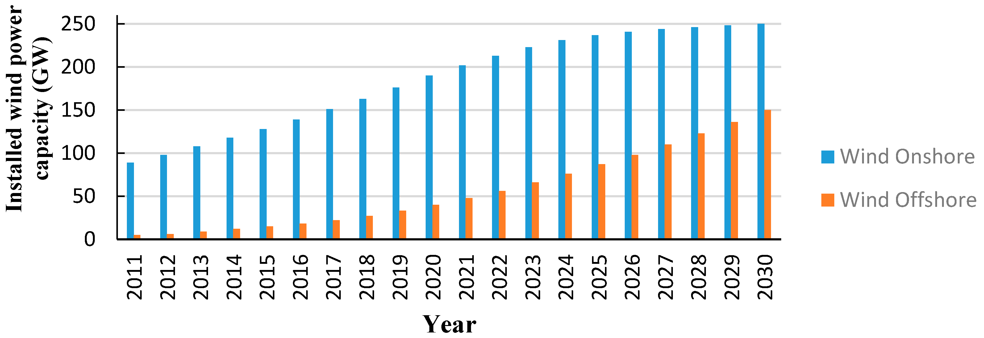
Figure 2.
Wind Turbine Power Curve.

Figure 3.
The power coefficient curves with different pre-setting pitch angle.

Figure 4.
Pitch angle controller for variable speed wind turbine.

Figure 5.
The relation between rotor power coefficient and tip speed ratio.
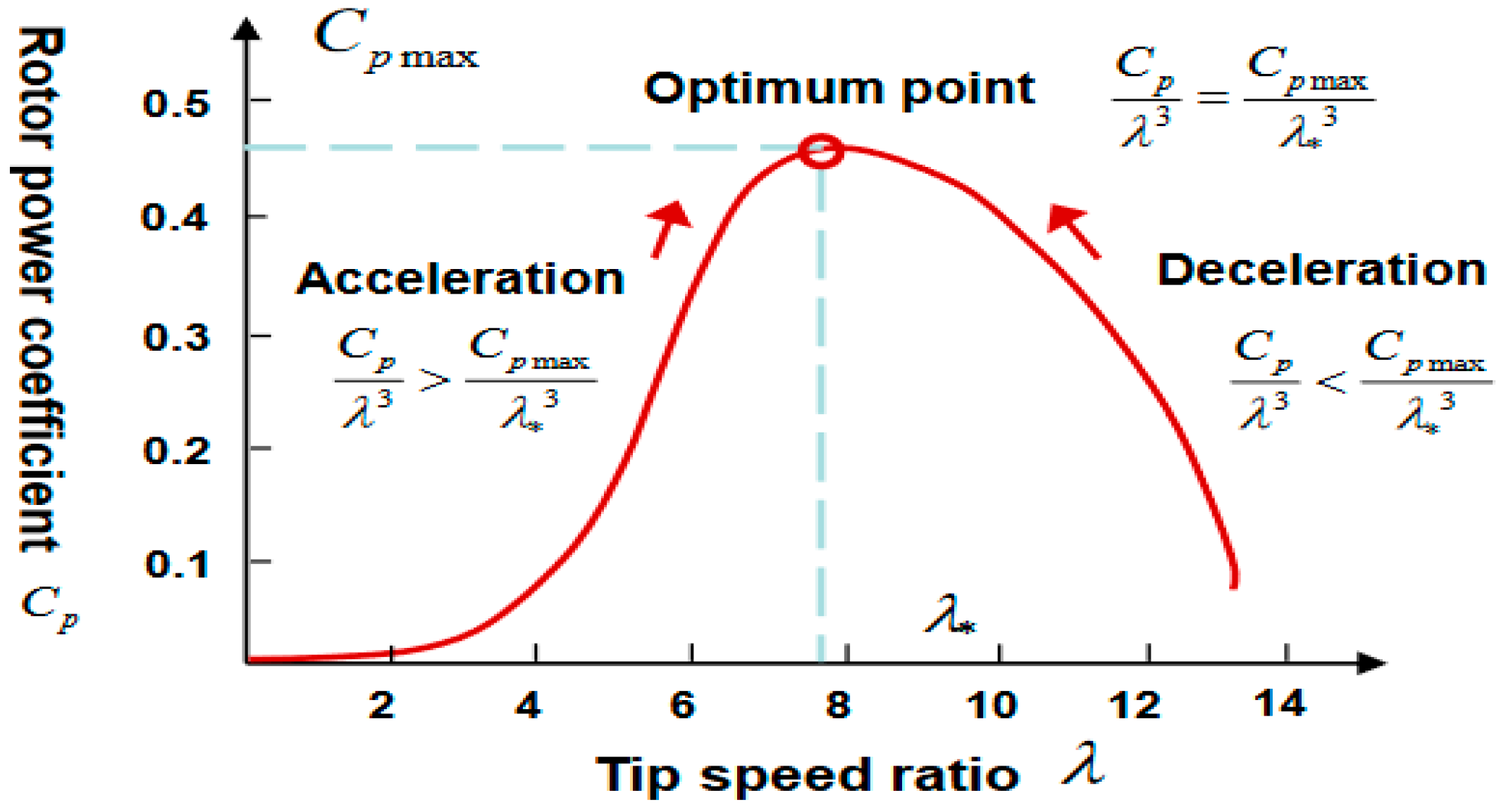
Figure 6.
The block diagram of optimal torque control method.

Figure 7.
The configuration of WT-PMSG system.

Figure 8.
Equivalent circuit of PMSG in: (a) d-axis and (b) q-axis.
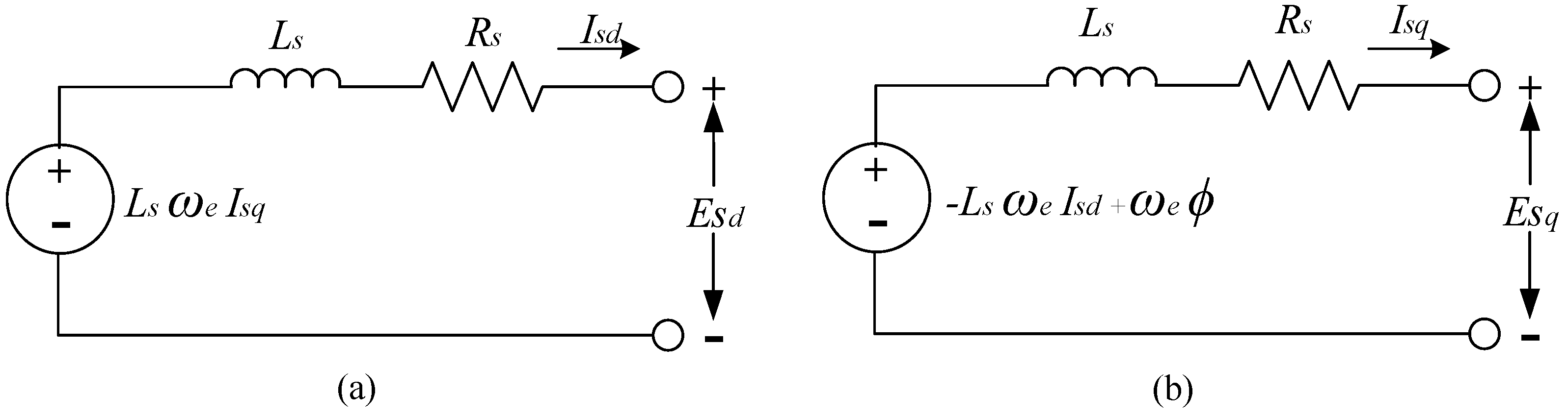
Figure 9.
Control loops of a generator side converter with PMSG Wind turbine.
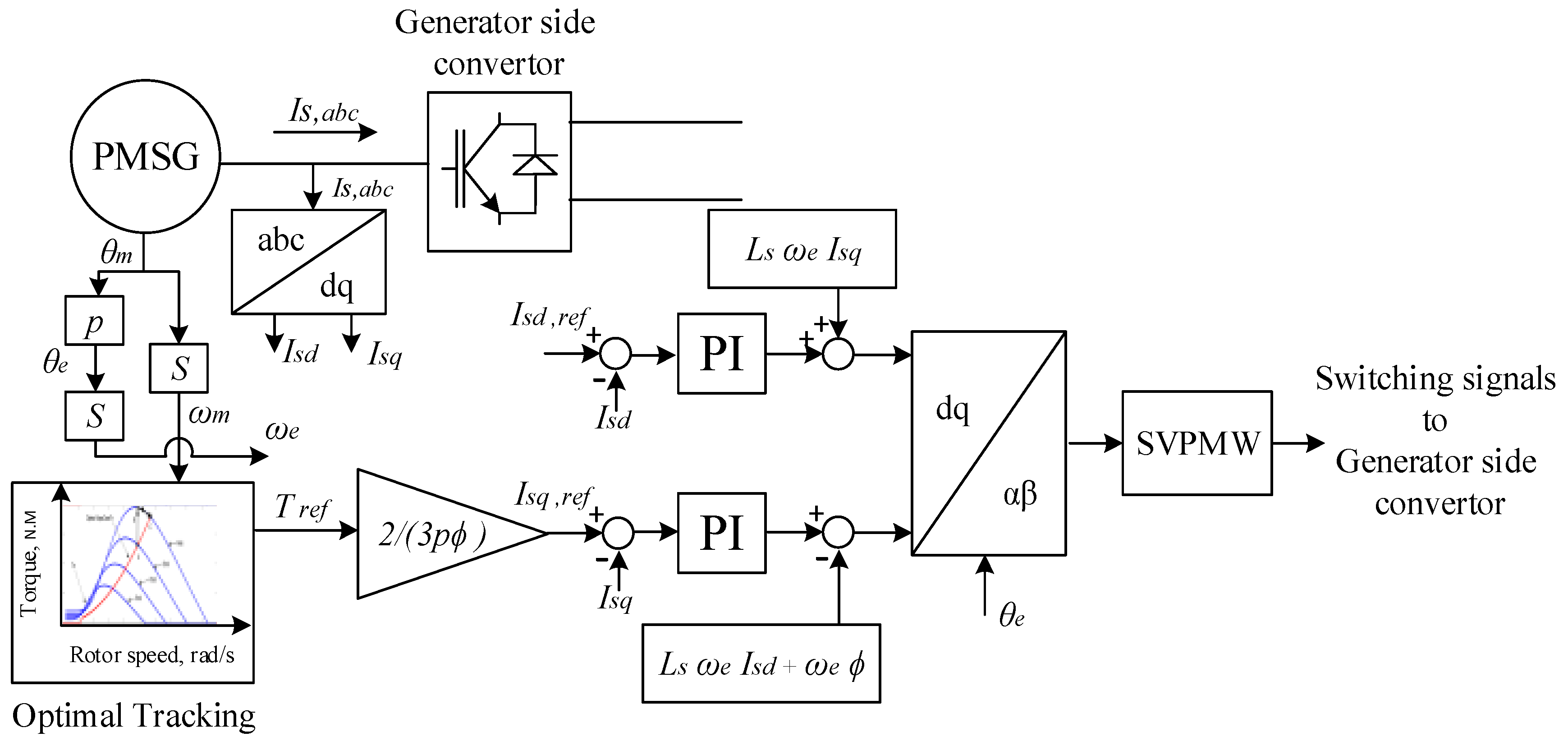
Figure 10.
Control loops of a grid side converter with AC grid.
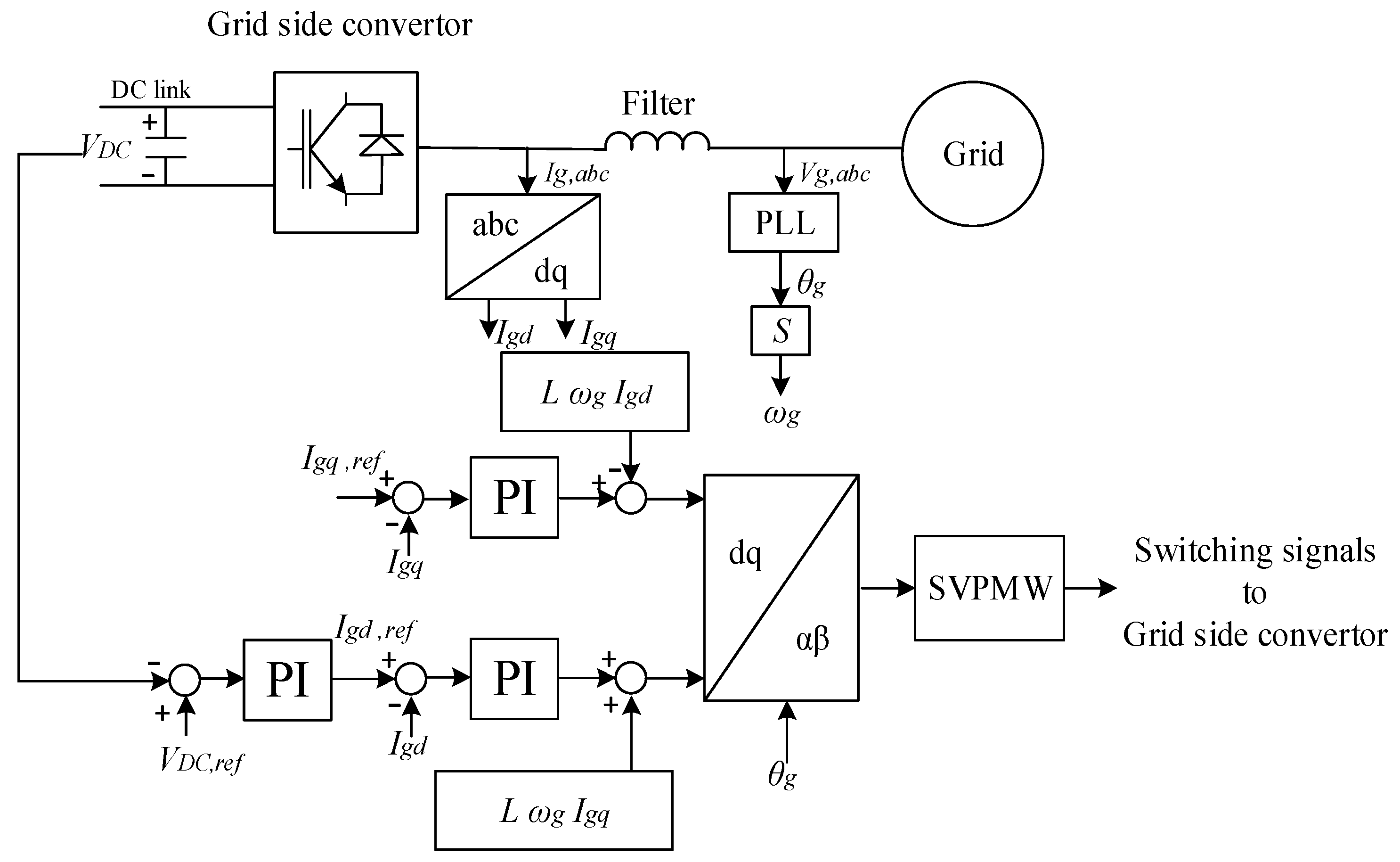
Figure 11.
Schematic diagram of typical VSC-HVDC system.

Figure 12.
Averaged model of VSC.
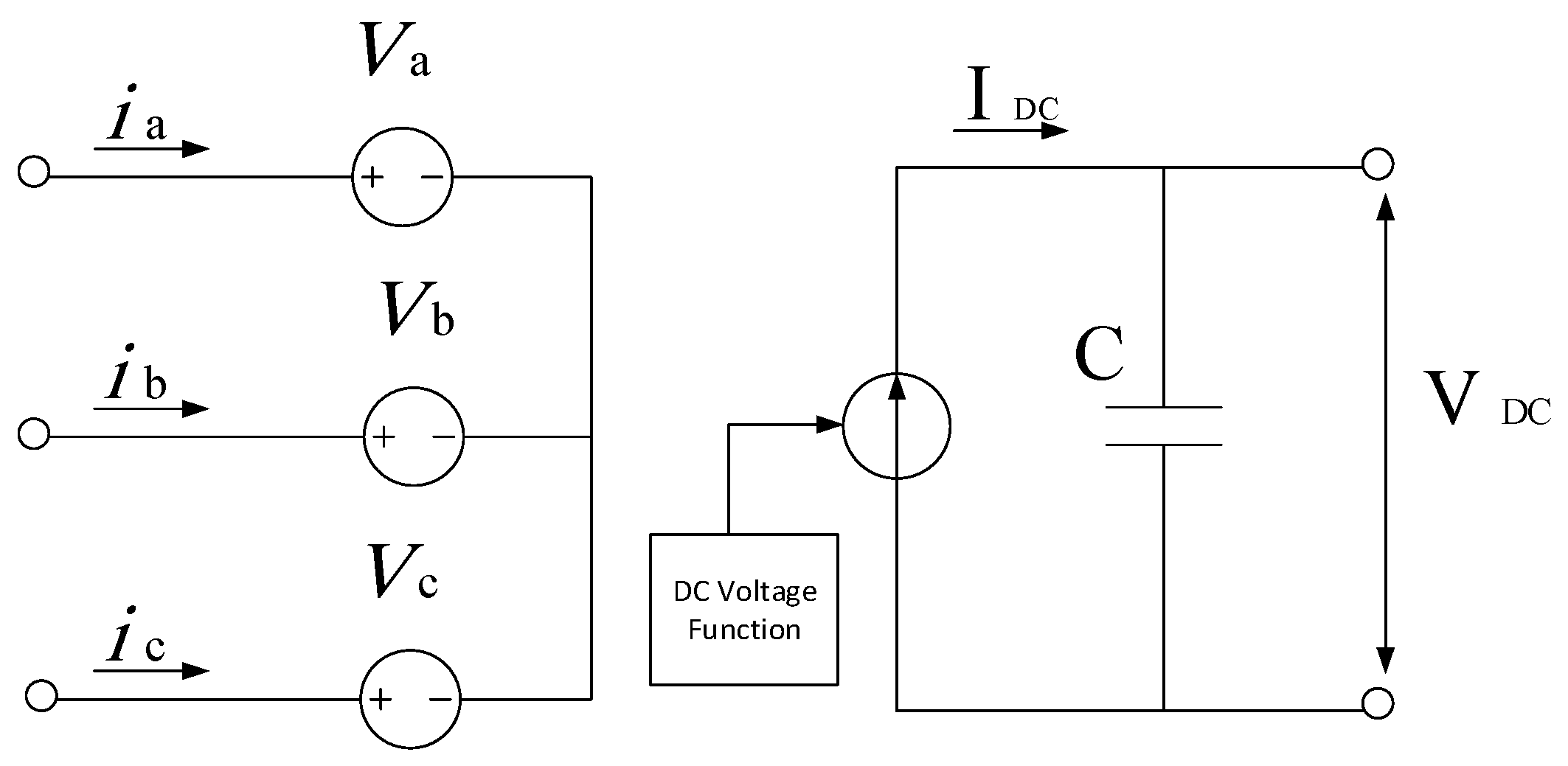
Figure 13.
Single line representation of VSC-HVD circuit.
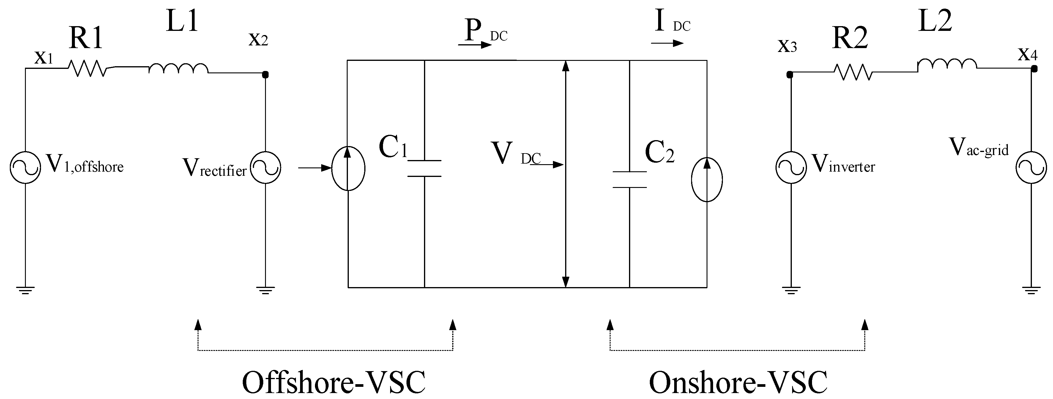
Figure 14.
Block diagram of the VSC-HVDC control system.

Figure 15.
Characteristics of the three modes for outer controller: (a) constant power control; (b) constant voltage control; and (c) DC voltage droop control.
Figure 15.
Characteristics of the three modes for outer controller: (a) constant power control; (b) constant voltage control; and (c) DC voltage droop control.

Figure 16.
Modes of frequency control in Great Britain.
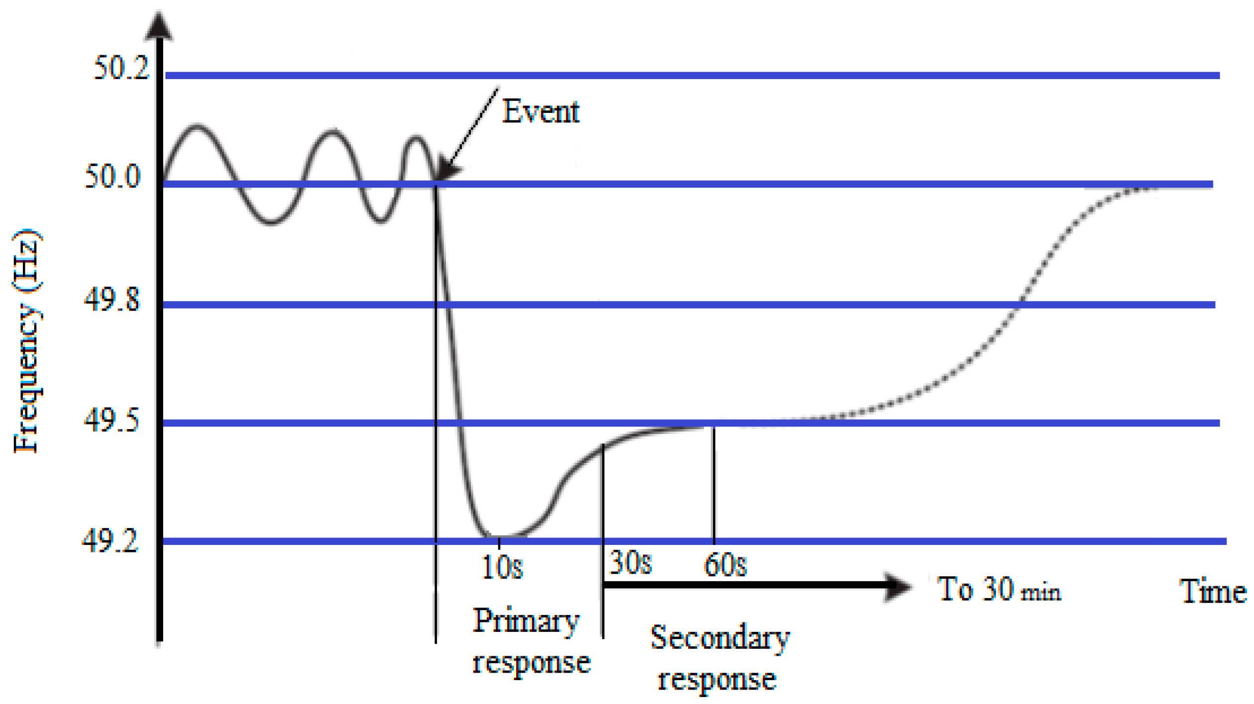
Figure 17.
Schematic of inertial controller form torque control.
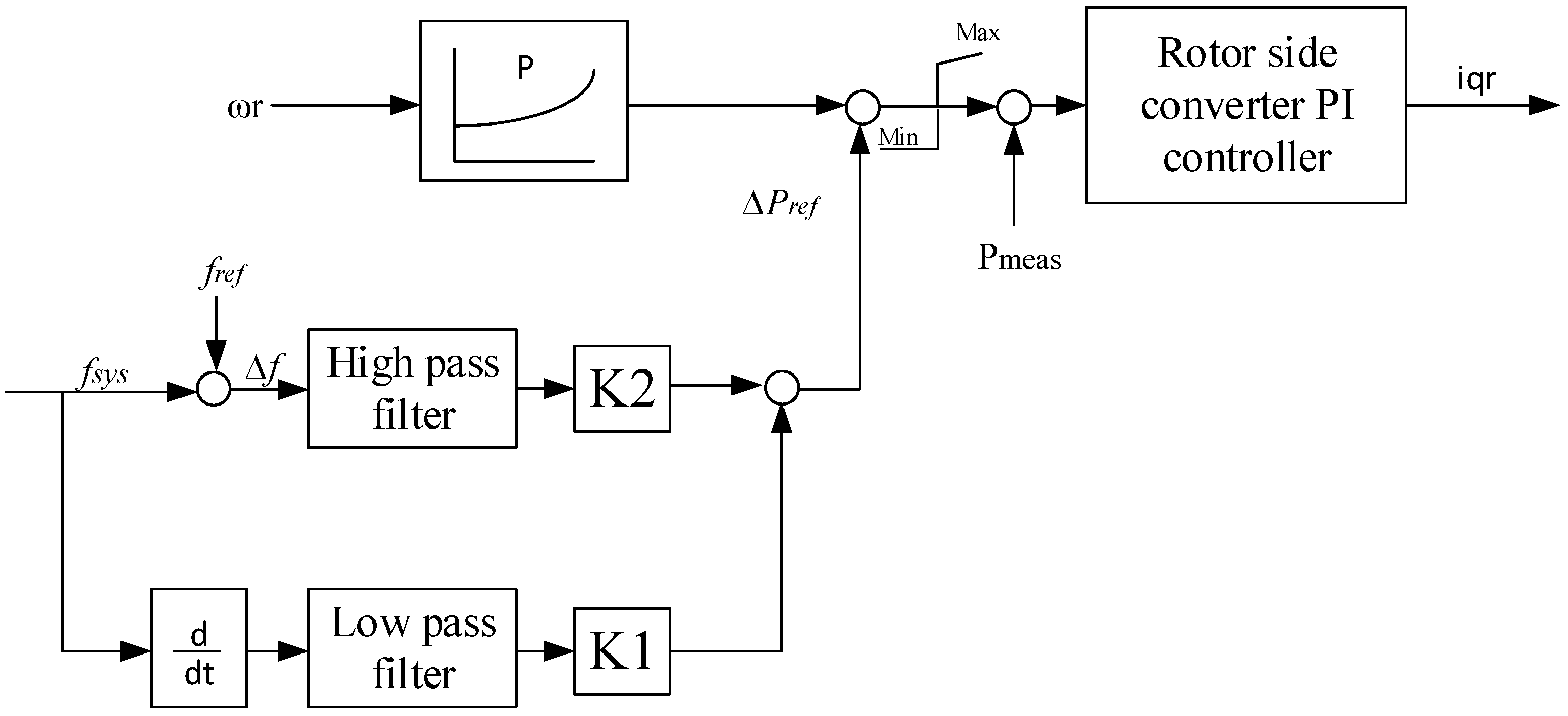
Figure 18.
Wind turbine blade pitch angle control.
Figure 19.
A de-loaded active power curves by changing the rotor speed.

Figure 20.
Pitch control schematic.

Figure 21.
The (P-ω) curve when applying pitching control for a wind turbine at speed 10 m/s.

Figure 22.
Different frequency response in the previous three cases: case (1): Without frequency support from variable speed-WTs and VSC-HVDC, case (2): Activating frequency controller of variable speed-WTs only and case (3): Activating frequency controller of variable speed-WTs with VSC-HVDC.
Figure 22.
Different frequency response in the previous three cases: case (1): Without frequency support from variable speed-WTs and VSC-HVDC, case (2): Activating frequency controller of variable speed-WTs only and case (3): Activating frequency controller of variable speed-WTs with VSC-HVDC.

Figure 23.
Effect of the frequency regulation in the three cases for; (a) speed of wind turbine generator; (b) pitch angle; (c) offshore active power production.
Figure 23.
Effect of the frequency regulation in the three cases for; (a) speed of wind turbine generator; (b) pitch angle; (c) offshore active power production.
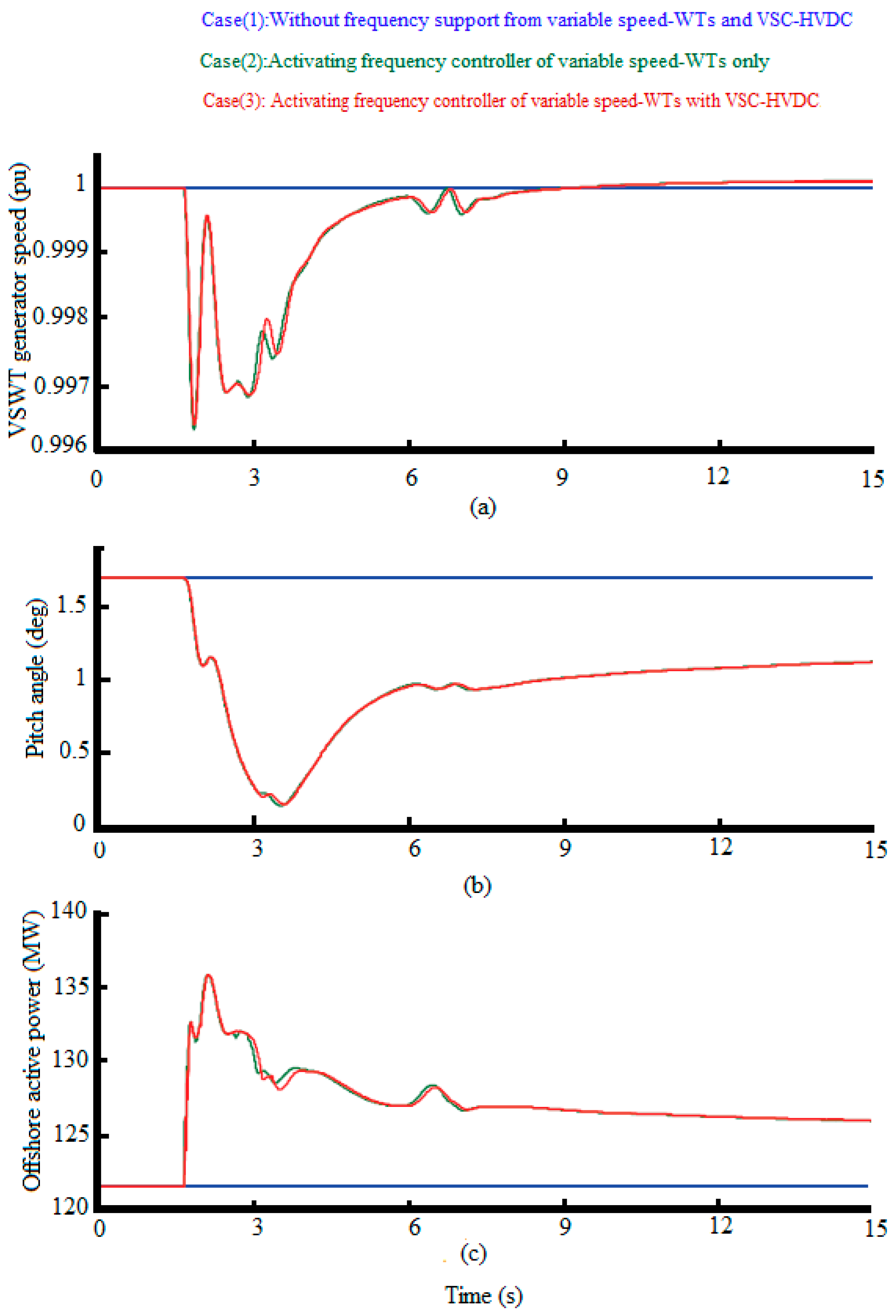
Figure 24.
Effect of the VSC-HVDC frequency regulation in the three cases for; (a) DC link voltage; and (b) onshore VSC active power production.
Figure 24.
Effect of the VSC-HVDC frequency regulation in the three cases for; (a) DC link voltage; and (b) onshore VSC active power production.

Figure 25.
The influence of time communication delays for an unexpected increasing load; (a) AC grid frequency response; (b) DC link voltage; and (c) onshore VSC active power production.
Figure 25.
The influence of time communication delays for an unexpected increasing load; (a) AC grid frequency response; (b) DC link voltage; and (c) onshore VSC active power production.

Table 1.
The comparison between the types of wind turbine.
| Indices | Type I | Type II | Type III | |
|---|---|---|---|---|
| Wind Turbine concepts | Fixed speed wind turbine (FSWT) | Variable speed wind turbine with double-fed induction generator | Variable speed wind turbine with full power converter | |
| Generator | Squirrel cage induction generator (SCIG) | Double-fed induction generator (DFIG) | Wound rotor synchronous generator (WRSG), and permanent magnet synchronous generator (PMSG). | |
| Grid Connection | -Directly via transformer-Need soft start and capacitor Bank | Partial scale converter | Full-scale converter | |
| Drive Train | Gear | Gear | Gear (DCSG/PMSG) SCIG | Gearless (Multi-pole DCSG/PMSG) |
| Speed Range | Nsync (~2% Slip) | (0.7–1.3) Nsync~(−30 ± 30% Slip) | (0~1) Nrated | |
| Blade angle control | Stall/active stall control, Pitch Control | Pitch Control | Pitch Control | |
Table 2.
De-loading techniques based on the range of the level speed.
| Indices | Operating Regions for Wind Turbines | ||
|---|---|---|---|
| Low Wind Speed Range (3–7) m/s | Medium Wind Speed Range (8–13) m/s | High Wind Speed Range (13–25) m/s | |
| Operation Conditions of Wind Turbine | Always Wind turbines operate at partial load. The rotating speed of the turbine does not reach its rated value at any time. | Mostly Wind turbines operate at partial load. The rotating speed of the turbine reaches its rated value transiently. | Wind turbines operate at full load. The rotating speed of the turbine reaches its rated value. The power extracted from the wind should be not to exceed the ratings of the generator |
| De-loading Techniques Used | Over speeding techniques are used only. | Over speeding techniques are used and Pitch Control techniques may be used depends on its rated value of the rotating speed. | Pitch Control techniques are used only for applying de loading and regulate the rotational speed. |
Table 3.
Summaries various control configuration for voltage source converter-high voltage direct current.
Table 3.
Summaries various control configuration for voltage source converter-high voltage direct current.
| Control Modes | Features | |
|---|---|---|
| Rectifier | Inverter | Notes |
| Constant power | Constant power | Not applicable |
| Constant dc voltage | Constant dc voltage | |
| Constant power | DC droop | It applicable but with risk of DC over voltage |
| Constant power | Constant DC voltage | |
| DC droop | Constant power | Good performance power flow by inverter |
| Constant dc voltage | Constant power | |
| DC droop | Constant dc voltage | Acceptable, power flow control by the rectifier. |
| Constant dc voltage | DC droop | Acceptable, power flow control by inverter |
| DC droop | DC droop | Good performance power flow by both |
Table 4.
Summary of frequency regulation strategies in grid integrated offshore wind turbines via VSC-HVDC technology.
Table 4.
Summary of frequency regulation strategies in grid integrated offshore wind turbines via VSC-HVDC technology.
| Levels of Participation Primary Frequency Control | Features and Drawbacks | ||||||
|---|---|---|---|---|---|---|---|
| Wind Farm level | Inertia response | Feature: Modification of DFIG/PMSG power reference by df/dt and ∆f of network frequency. | Method of Wind farm sensing for the actual AC grid frequency value and its deviation value. | Communication | Features: High cost. -Reliability issues will prevent the development event of delay or communication failure can threaten the operation of wind farm with primary frequency control capability | ||
| Advantage :Fast response capability associated with electronically controlled VSWT | |||||||
| Power reserve | Pitch control | Feature :High installation cost, exploiting wind farm below its maximum power extraction capability ,Prefer works when generator work close to rated power | |||||
| Speed control | Over-speeding de-loading | Features :It is more usable but should make sure the rotor speed does not exceed its upper limit | Communication-less | Features: Construe the frequency of main ac grid to the equivalent variation of HVDC link voltage controlled by Grid side-VSC, which is detected by the WF-VSC and communicated to the wind farm. The cost is less. | |||
| Under-speeding de-loading | Features: -Not use since: -it decrease in small signal stability and -deceleration of the rotor in order to reduce the active power output would transiently lead to an increase on active power | ||||||
| HVDC system level | Energy stored in HVDC link like DC capacitor | Advantage: Providing a very fast response toward the main ac grid and decreasing the overwork of wind turbine. | |||||
| Drawbacks: Required a very large capacitance to be able to convert active power in an efficient way. | |||||||
| Coordinate blending wind turbine with HVDC system levels | Advantage: Fast response toward the AC grid frequency while not required the immoderate capacity of capacitance nor high-performance requirements on the wind farm. | ||||||
| Drawbacks: The dependence only on the frequency response capability of the offshore wind turbine has a disadvantage of dealing with delays and disturbances to the response due to many information transmission stages existing between the frequency measurement at the Gide Side-VSC and the wind turbine response | |||||||
© 2017 by the authors. Licensee MDPI, Basel, Switzerland. This article is an open access article distributed under the terms and conditions of the Creative Commons Attribution (CC BY) license (http://creativecommons.org/licenses/by/4.0/).
Share and Cite
MDPI and ACS Style
Jallad, J.; Mekhilef, S.; Mokhlis, H. Frequency Regulation Strategies in Grid Integrated Offshore Wind Turbines via VSC-HVDC Technology: A Review. Energies 2017, 10, 1244. https://doi.org/10.3390/en10091244
AMA Style
Jallad J, Mekhilef S, Mokhlis H. Frequency Regulation Strategies in Grid Integrated Offshore Wind Turbines via VSC-HVDC Technology: A Review. Energies. 2017; 10(9):1244. https://doi.org/10.3390/en10091244
Chicago/Turabian StyleJallad, Jafar, Saad Mekhilef, and Hazlie Mokhlis. 2017. "Frequency Regulation Strategies in Grid Integrated Offshore Wind Turbines via VSC-HVDC Technology: A Review" Energies 10, no. 9: 1244. https://doi.org/10.3390/en10091244
Note that from the first issue of 2016, this journal uses article numbers instead of page numbers. See further details here.