Numerical Simulation and Optimization of the Melting Process of Phase Change Material inside Horizontal Annulus

School of Energy Science and Engineering, Central South University, Changsha 410083, China
*
Author to whom correspondence should be addressed.
Energies 2017, 10(9), 1249; https://doi.org/10.3390/en10091249
Submission received: 16 July 2017
/
Revised: 18 August 2017
/
Accepted: 20 August 2017
/
Published: 23 August 2017
(This article belongs to the Section D: Energy Storage and Application)
Abstract
:Latent heat storage (LHS) technologies adopting phase change materials (PCMs) are increasingly being used to bridge the spatiotemporal mismatch between energy production and demand, especially in industries like solar power, where strong cyclic fluctuations exist. The shell-and-tube configuration is among the most prevalent ones in LHS and thus draws special attention from researchers. This paper presents numerical investigations on the melting of PCM, a paraffin blend RT27, inside a horizontal annulus. The volume of fluid model was adopted to permit density changes with the solidification/melting model wherein natural convection was taken into account. The eccentricity and diameter of the inner tube, sub-cooling degree of the PCM, and the heating-surface temperature were considered as variables for study. Through the evaluation of the melting time and exergy efficiency, the optimal parameters of the horizontal annulus were obtained. The results showed that the higher the heating boundary temperature, the earlier the convection appeared and the shorter the melting time. Also, the different eccentricity and diameters of the inner tube influenced the annulus tube interior temperature distribution, which in turn determined the strength and distribution of the resulting natural convection, resulting in varying melting rates.
1. Introduction
Energy has paramount significance for our survival. However, with the rising energy consumption in recent years, the energy industries are struggling to fully meet the needs of people, to a large extend due to energy wastage. One of the main causes of such wastage is the spatiotemporal mismatch between energy production and demand, especially in industries like solar power, where strong cyclic fluctuations exist. An energy storage system, an important approach to the frugal utilization of energy, can reserve and release residual energy when needed and improve energy utilization effectively by bridging the aforementioned mismatch [1,2].
To that end, latent heat storage (LHS) technologies adopting phase change materials (PCMs) are increasingly being used due to their high energy storage density and nearly constant charging/discharging temperature. Among the many possible configurations, the shell-and-tube type LHS unit has the advantages of compactness, small heat loss, and technological maturity [3]. It is used in applications such as water heating systems, air heating systems, cookers, green houses, and buildings [1]. Most noticeable is the recent trend of the shell-and-tube LHS unit being integrated into solar thermal power systems, as seen in the applications studied by Li et al. [4] and Tehrani et al. [5]. Consequently, the shell-and-tube type LHS unit was the subject of a number of analytical [6,7,8,9], experimental [10,11,12,13], and numerical [14,15,16,17,18,19,20,21,22] studies, which focused mostly on performance enhancements at the charging/discharging-stage of the unit.
The unconstrained melting of PCM inside a horizontal tube was studied by Bareiss and Beer [6], and a solvable analytical model was presented that took gravity into account. For the PCM melting in a vertical tube with a specific set of boundary conditions, Chen et al. [7] gave the analytical solutions of parameters such as melting rate and heat storage. With the aid of scale analysis, Bejan, Lorente et al. analytically studied the melting of PCM in a vertical tube heated by an inner tube [8] and in a horizontal tube heated by an invading line [9].
Al-Abidi et al. [10] and Rathod and Banerjee [12] experimentally investigated the effect of added fins to the shell-and-tube type LHS unit and found that appropriate usage of fins had a positive impact. Yazici et al. [11] studied solidification in a horizontal shell-and-tube type LHS unit and found that eccentricity in the direction that strengthens natural convection accelerated solidification. The application of dynamic melting, which recirculates the liquid PCM to decrease melting time, was investigated by Gasia et al. [13]. Great gains were observed with negligible pumping power consumption.
Without the need to setup and periodically calibrate an experimental system, a well-established numerical model has the advantage of solving many cases in a reasonably short period of time, thus allowing the exploration of more ideas and greater innovativeness. For example, Liu et al. [14] explored the idea of utilizing inner tubes of various sizes and numbers in a shell-and-tube type LHS unit. It was found that proper arrangements of the hierarchical inner tube design can decrease melting time. Along the same line of geometric investigations, Darzi et al. [16], Tabassum et al. [19], and Kuboth et al. [21] explored new ideas of geometrically altering the shell-and-tube type LHS unit to enhance the heat transfer performance.
The annular configuration is the most basic of the shell-and-tube LHS unit configurations because it has only one inner tube. Using the numerical method, this paper aims to shed light on the effects of the eccentricity and diameter of the inner tube, sub-cooling degree of the PCM, and the heating-surface temperature on the performance of the annular LHS during the charging stage. With the paraffin blend RT27 as the PCM and water as heat transfer fluid, a mathematical model of the annular LHS unit was established. The evolution of four thermal parameters over time was discussed to unveil the effects of the studied factors.
2. Numerical Study
2.1. Physical and Numerical Model
We considered an annular LHS unit as shown in Figure 1, with water in the inner tube and the paraffin blend RT27 filled in the annulus. The diameters of the inner-tube and outside-shell were 20 and 40 mm, respectively. The heat transfer fluid was assumed to still be in the circular tube and exchanging heat with the PCM outside. Water and RT27 were initially at a sub-cooled temperature below the PCM solidus temperature. The PCM then melted by receiving heat from the outer shell, which was set to a high temperature above the liquidus temperature. This is the configuration seen more often in applications involving the storage of solar energy, which is concentrated and radiated on to the outer shell.
The thermal physical parameters used in this paper were taken from the reference [23]. RT27 had a liquidus temperature of 303 K and a solidus temperature of 301 K. Other relevant properties of the material were treated as constants in the fully solid or liquid state, but not as constants in the mushy zone, where they varied linearly with temperature, until they reached the constant value in the liquid and solid zones, as listed in Table 1. An exception to this is that the density of liquid RT27 took on the Boussinesq assumption when it contributed to buoyancy, for which the reference temperature was 301 K. In the melting process, the decreasing density caused volumetric expansion. Thus, an air region above was added to provide space for the expansion. The paraffin filled about 85% of the volume, while the remaining region was filled with air, modeled as compressible ideal gas, whose properties can also be found in Table 1.
The time step for the simulation was 0.005 s, which was sufficiently small to avoid the divergent residual error caused by the complexity of the conjunctive application of the volume of fluid (VOF) model and the solidification/melting model. The melting fraction was monitored on a volume-averaged basis, and the mass-averaged temperature of the whole region was tracked for entropy calculation, both at 1 s intervals. The computations were terminated when the liquid fraction reached unity, which was the point where all the curves in the next sections ended.
The computations were performed using a commercially available finite volume CFD package Fluent. The coupling of pressure and velocity, the pressure discretization scheme, the momentum equation discretization scheme, and the energy equation discretization scheme were the SIMPLEC algorithm, the standard scheme, the first order upwind scheme, and the first order upwind scheme, respectively.
Different grid sizes were selected and tested to check the independency of the adopted grid size. By comparing the melting fractions, an arrangement of proper grids was adopted for the numerical study.
2.2. Governing Equations
The enthalpy-porosity method and the VOF model were used to simulate the melting process of PCM inside the annulus and the PCM-air system with a moving internal interface without inter-penetration of two media, respectively. For a larger axial-radial ratio, the LHS unit can be investigated by focusing only on its cross-section, reducing the dimension of the study from three to two. Thus, the flow was considered unsteady, laminar, and two-dimensional. The viscous dissipation term was considered negligible. Consequently, the governing equations used here for the PCM-air system are in accordance to the reference [24] shown as follows.
Continuity:
Momentum:
Thermal energy:
where an is the nth fluid’s volume fraction, p is the pressure, ρ is the density, k is the thermal conductivity, μ is the dynamic viscosity, Si is the momentum source term, ui is the velocity component, h is the enthalpy, defined as the sum of the reference enthalpy href, the sensible enthalpy which is an integral, and the latent heat enthalpy ΔH.
The latent heat content ΔH is computed by the latent heat L of the material,
β is the melting fraction which will vary as,
The sources term Si in momentum equation is added due to phase change effect on convection, given by,
where the coefficient C is a mushy zone constant fixed at a value of 105, which is an empirical value used in previous studies [14], and ε is a small number (0.001) to prevent division by zero.
It should be point out that natural convection, which was simulated by the buoyancy term in the momentum equation in tandem with the Boussinesq assumption, plays a very significant role in the melting process. Without natural convection, and without any other driving force of momentum in the physical model, heat transfer within a fluid medium would be no different from that within a solid medium, since there is zero velocity in the entire domain, and no convection heat transfer exists. This would lead to erroneous results.
2.3. Dimensionless Analysis
Dimensionless variables are computed in order to reach generalized results.
- Fourier number, the dimensionless time:where R is the characteristic length, which is the shell diameter.
- The dimensionless temperature:where TM = 302 K is the average phase-change temperature and TW is the boundary temperature.
- Stefan number:where L is the phase-change enthalpy. The Stefan number varies with the shell temperature and thus can be defined as the dimensionless boundary temperature.
- Degree of sub-cooling:where Tini is the initial (sub-cooled) temperature of the paraffin.
- The dimensionless offset Xoff and inner-tube diameter Xr:Xoff = Δ/Dwhere Δ is the relative offset of the centers, d0 is the inner-tube diameter and D is the constant shell diameter.Xr = d0/D
- Since in the investigated system have no heat loss, its energy efficiency will always be 100%. Thus the energy efficiency is not a suitable index of performance measurement. Instead, the exergy efficiency ηex was used:where is the change in exergy of the system, and is the exergy input from the high temperature shell, both of which satisfy the exergy balance.where I is the exergy destruction, which can be determined with,where Π is the entropy production, which satisfies the entropy balance:where is the heat transfer through the shell over the ith time step, and the summation item is the total change in entropy at the shell from the start of the simulation to time step t. is the change in entropy of the system, which can be determined by:where , , and are the heat transferred into the PCM region, the air region, and the water region, respectively; , , and are the mass weighted average temperature of the PCM region, the air region, and the water region, respectively.
Finally, can be determined by,
During the simulations, the variables , , , , , , and were monitored to provide inputs for Equations (15)–(20), which enabled the calculation of .
2.4. Parametric Variables
The default values of the parameters in the study were: concentric inner tube, with diameters of the inner-tube and outside-shell as 20 and 40 mm, respectively, the initial temperature is 300 K, and the constant boundary wall temperature is 333 K. By keeping other parameters constant, one of the parameters was changed for the numerical computation to investigate the influence of various parameters on the heat transfer process of the LHS unit. The parameters and their values to be studied are given in Table 2 in both dimensional and dimensionless forms.
3. Results and Discussion
3.1. Default Configuration
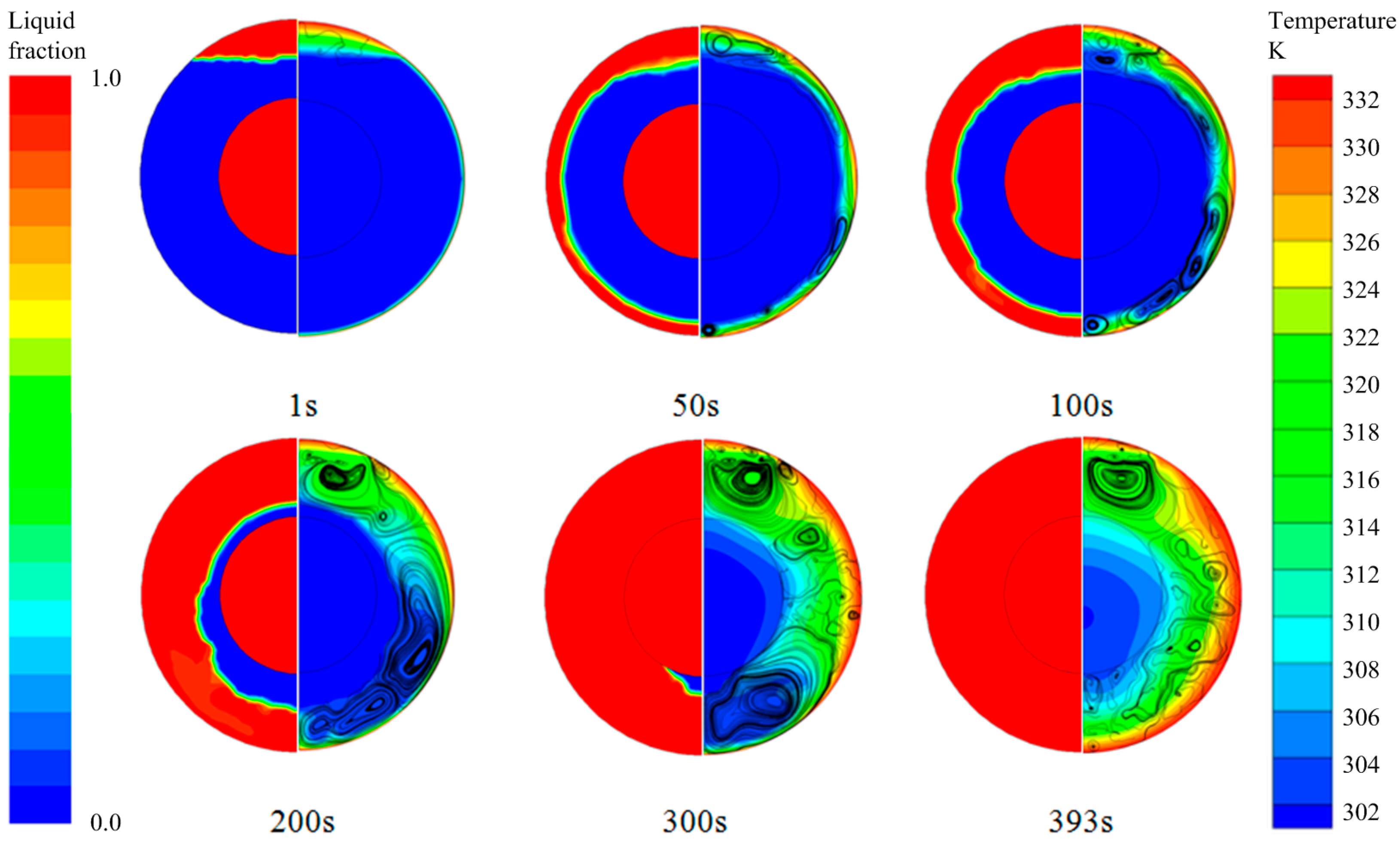
Figure 2 shows the evolution of the melting PCM for the default values of the studied parameters. The unstable complex structure was near the top of the wall area, which made the solid-liquid interface appear wavy. In the beginning of the melting process, solid PCM was in contact with the shell wall. Heat transferred from the wall to the PCM was mainly through heat conduction. A very thin liquid layer began to form between the wall and the solid phase. As the liquid region grew over time, the influence of conduction decreased in comparison with natural convection occurring at the phase interface, resulting in upward flows at the heated surface and downward flows at the cold surface, forming strong circulations. When the liquid layer reached the inner tube, due to the inner tube being filled with water at a lower temperature, some heat began to transfer to the water inside, which slowed the melting rate.
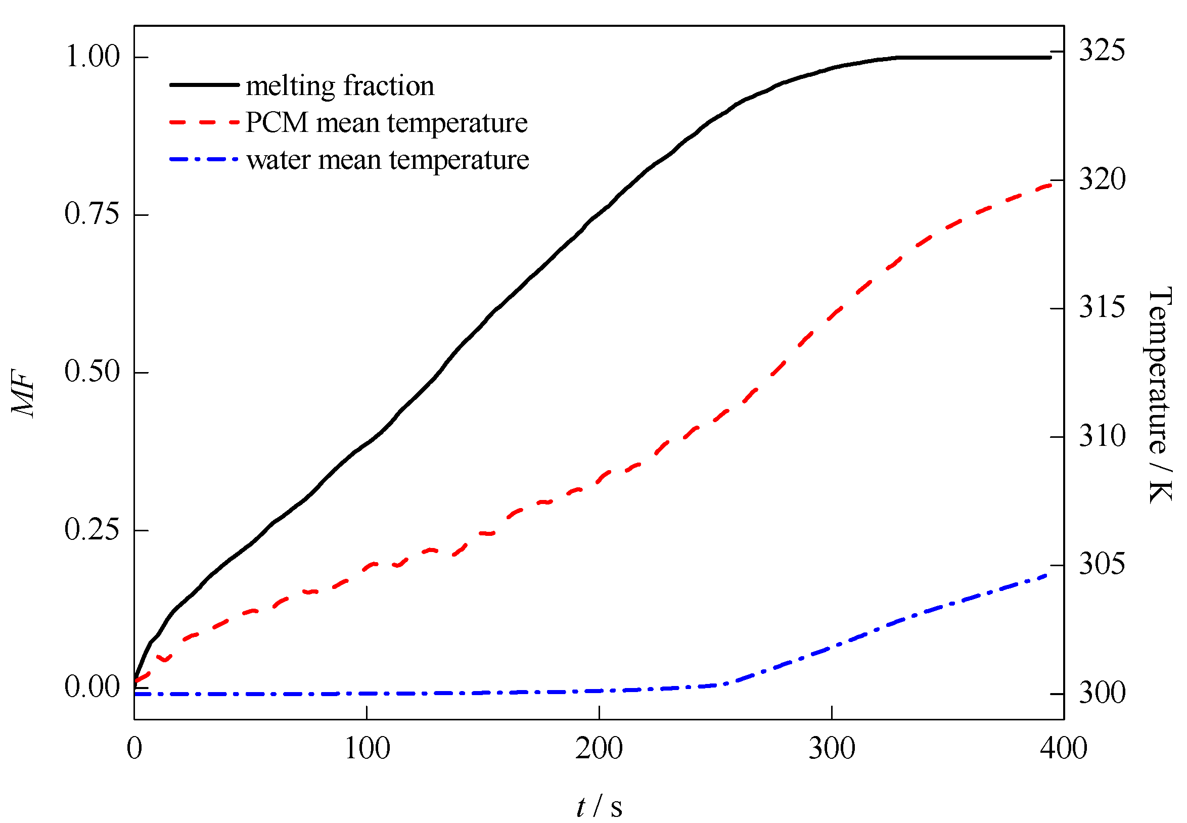
The quantified evolution of the melting fraction, mean PCM temperature and mean water temperature are shown in Figure 3. At the beginning of the melting process, the PCM mean temperature rose the fastest, which was due to the close contact with the heated shell. As the actual melting commenced, more heat was stored as the latent heat, resulting in the decreased rising rate of PCM temperature. As the liquid region expanded in time, natural convection started to dominate, resulting in the increased rising rate of PCM temperature. The water temperature, on the other hand, barely rose in the first 250 s, after which time the inner tube came into contact with the liquid PCM, and the mean water temperature started to rise at a faster rate.
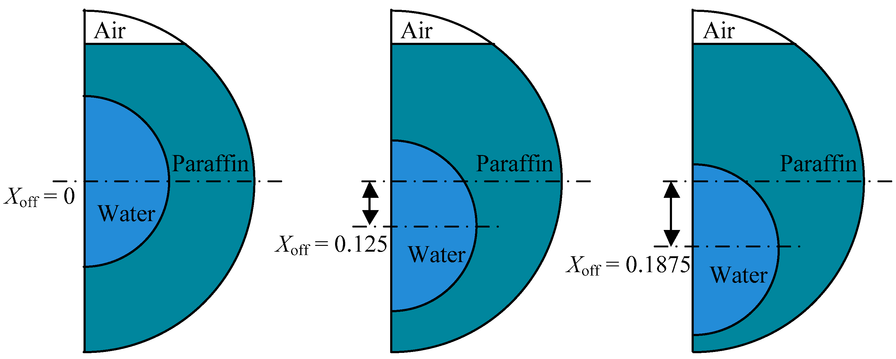
3.2. Eccentricity
To discuss the influence of the inner tube eccentricity, the offset of the inner tube and outer shell center was taken as the discussed parameter. Three conditions for analysis are Xoff = 0, 0.125, and 0.1875. The structural schematics are shown in Figure 4.
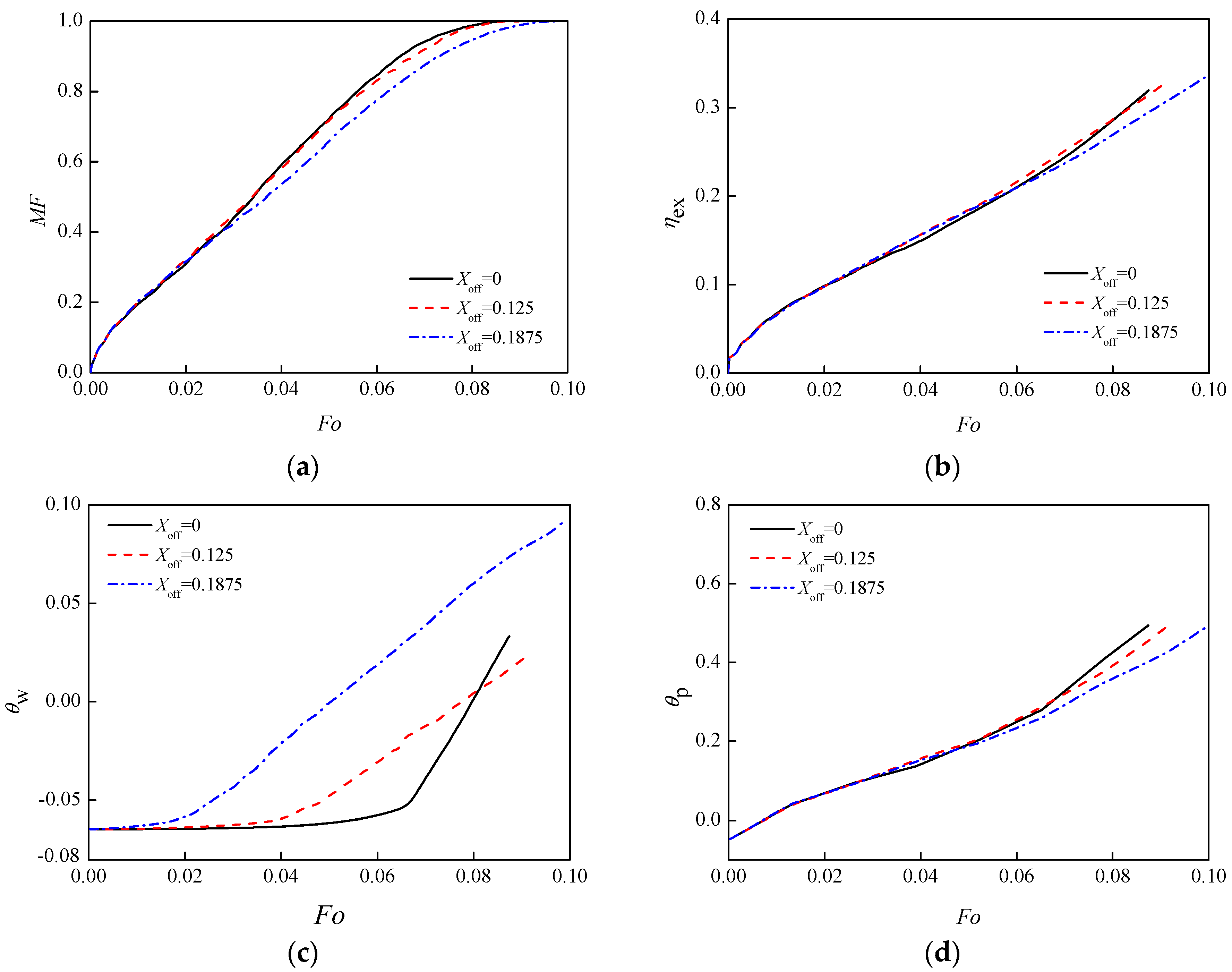
As shown in Figure 5, the trends of the PCM temperature and exergy efficiency curves were similar, rising slowly with a constant slope. The melting fraction figure showed that in the beginning, the three curves kept a similar melting rate and began to diffrentiate after Fo = 0.02. Tubes of concentric structure and offset of the Xoff = 0.125 had a relatively faster melting rate. For the lager offset, Xoff = 0.1875, the melting rate was slower. This is because the natural convection area was weaker at the bottom, and heat transfer was mainly through heat conduction. The coefficient of thermal conductivity of paraffin was very small, so paraffin wax melting process in the annulus with a large offset was very slow. The eccentricity had a certain impact on the paraffin wax melting rate, as it determines the proportion of convection and conduction of heat in the system.
Due to low thermal conductivity of paraffin, the heat transfer rate was very small when the heat was mainly transferred by conduction. However, when the main heat transfer form changed to convection, the heat transfer rate increased greatly.
Convection was most likely to appear at the bottom of the tube. At the beginning, the three curves’ growth rate were similar with no convection. Then, the liquid phase began to appear, and solid and liquid paraffin coexisted, which caused convection, and the curves began to differentiate. The inside tube was filled with water. When eccentricity was large, the natural convection area at the bottom became smaller, so the lowest tube position had the biggest influence on melting time and the slowest melting rate.
The average temperature of water in the inside tube also had differences. When the inner tube position was lower, the temperature was affected by the shell temperature more quickly, so the temperature rise began at about Fo = 0.01. Due to the thickest solid layer outside the inner tube of the concentric tube and the low thermal conductivity of solid paraffin, the inner tube wall was influenced by outer wall temperature last, so the temperature changed the slowest. However, after temperature rose, the rate became the fastest. This was due to heat from the external tube beginning to affect the inner tube. Most of external paraffin has been melt, resulting in a large proportion of the liquid PCMs area, with strong heat convection and transfer. When PCMs of the outer tube were melt completely, the water temperature of the tube with offset of Xoff = 0.1875 was highest.
For the heat transfer of the whole unit, due to the same boundary temperature, degree of sub-cooling and paraffin filling amount, the different locations of the cooling water in the tube only influenced the rate of heat-exchange process. The melting fraction, the exergy efficiency and the temperature change of paraffin in the outside tube under three conditions were similar.
3.3. Diameter of Inner Tube
Figure 6 gives the structural diagrams for different diameters of inner tube as Xr = 0.375, 0.5 and 0.625.
Figure 7 shows the melting evolution of the PCM in the process of melting for different inner tube diameters. The melting fraction and exergy efficiency curve of the three conditions had similar trends, rising slowly at a constant slope. In the melting fraction diagram, we can see that the three melting rates were significantly different from each other from the start, of which the tube with Xr = 0.625 melt fastest, and that of Xr = 0.5 was slower in melting rate. At Fo = 0.02, for the tube of Xr = 0.625, the melting fraction has increased to 0.4, while only to 0.3 and 0.2 for Xr = 0.5 and 0.375, respectively. When the tube diameters Xr = 0.375, 0.5, and 0.625, the complete melting time Fo of PCMs were 0.109, 0.087 and 0.079, respectively. In comparison with Xr = 0.5, the melting time of inner tube system with a larger diameter Xr = 0.625, is 8.98% faster. When the diameter Xr is 0.375, the melting time slowed by 25.45%. This was because, for the tube with Xr = 0.625, the tube spacing between inside and outside was small and the wax layer was thinner, so less time was needed for melting. At the same time, for the same shell diameter, large inner tube diameter yields less paraffin filling volume. This was also one of the reasons for a shorter melting time of the case with Xr = 0.625.
For exergy efficiency curve Figure 7b, when the boundary temperature and the initial temperature of the unit were constants, different tube diameters influenced the variation of the paraffin temperature in the whole unit, so the exergy efficiency varied. For the inside tube with Xr = 0.625, the temperature rising of paraffin was most obvious and also fastest, so the slope of exergy efficiency at the same time was greater than the other two.
For the average temperature of water in the tube, shown as Figure 7c, due to the small distance between the inner and outer tubes for Xr = 0.625, the liquid phase area extended close to the inner tube wall first and affected the temperature of water filled in the tube. So the water temperature started to change first for Xr = 0.625, whereas Xr = 0.375 was the slowest. But when the liquid phase area extended to the inner tube wall and began to affect the temperature of the water in the tube, due to the effect of tube diameter, the temperature acceleration of Xr = 0.375 with less water quality was affected more obviously. So when the tube water began to have temperature rise, the unit with Xr = 0.375 has rapid temperature change. For Xr = 0.625, although the water temperature was affected the earliest by the outer wall, due to large quality of water in the inner tube, the rate of the average temperature in the tube area change was slowest. When external paraffin melted completely, we can observe from the figure that the final temperature of water for the unit with Xr = 0.375, was the largest, and that of Xr = 0.625 was the lowest.
3.4. Surface Temperature
From Figure 8, we can see that the trend of three melting fractions and exergy efficiency curve were similar, being a slow rise at a constant slope. For the melting fraction curve, for the condition of Ste = 0.433, the melting rate was obviously faster, and the final melting time required was the least, while the unit with Ste = 0.222 was the slowest. Taking Ste = 0.337 as a reference, the melting time of Ste = 0.433 condition was 7.19% shorter, and the time of Ste = 0.222 was 18.56% longer. This was because for the same initial temperature for internal materials, the higher the external boundary temperature, the larger the temperature differences, the stronger the heat conduction, so the faster the melting speed.
For exergy efficiency, when the environment was at a certain temperature, the higher boundary temperature would cause larger temperature difference between the initial temperature and the shell temperature, and so result in the higher heat transfer efficiency. Thus, the exergy efficiency increased with the fast-changing temperature, but the exergy efficiencies of three conditions at the complete melting time were approximately the same, being 32.49%, 32.28%, and 34.16%, respectively. To raise the boundary temperature would not further improve the exergy efficiency of heat exchange unit, but it can accelerate the heat transfer rate and shorten the melting time.
The average temperature of the water in the tube in the initial case did not change until Fo = 0.06, after which different trends varied with the different working conditions. Before Fo = 0.06, as the external PCM was melting, the liquid phase had not yet affected the inside tube wall. The liquid phase area extended to affect the temperature of the water in the tube over time. When the temperature difference between the outer wall and the initial unit was bigger, the heat transfer efficiency was greater. The PCM in the outer tube with a fast temperature rise melted faster, so the liquid phase area spread to the inner wall first, which caused the temperature rise of the water in the tube. For the condition of Ste = 0.433, the average temperature of the water in the tube was affected by external liquid PCM first and rapidly rose. Likewise, that of Ste = 0.337 was slower, and of Ste = 0.222 was the slowest.
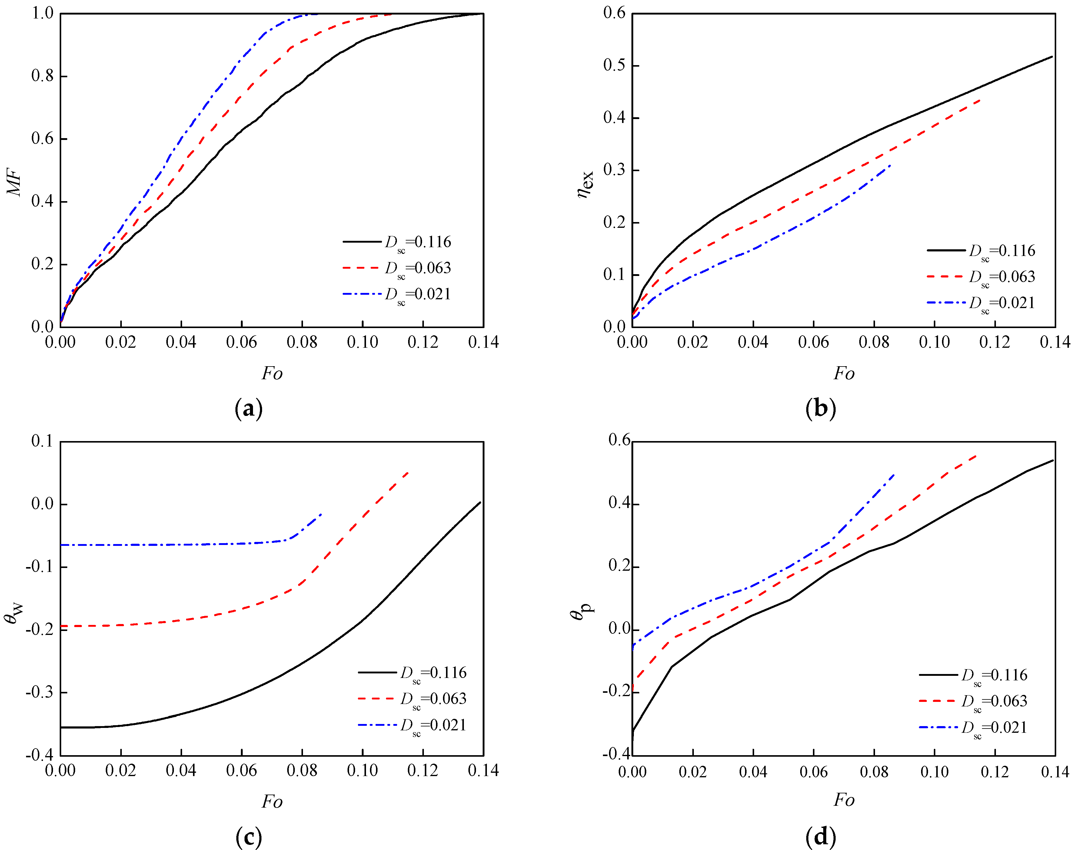
3.5. Sub-Cooling Degree
For different sub-cooling degrees, the trends of the temperature and exergy efficiency curves on three working conditions were similarly kept at a fixed slope and slowly rose.
For melting fraction curve Figure 9a, the three melting rates were different from the start, and the gap of the three increased with time. Among them, Dsc = 0.021 had a faster melting rate to 0.087 because with the condition of equal wall temperature, the shortest time was needed for the temperature rise to the PCM melting point, and for the Dsc of 0.063 and 0.021, the time increased by 30.54% and 59.58%.
For the exergy efficiency curve Figure 9b, the condition of Dsc = 0.116 started to change and kept rising from the beginning, higher than the other two. This was because the larger temperature difference between the PCM and the wall caused high heat transfer efficiency, which made its exergy efficiency greater than the conditions of Dsc = 0.063 and 0.021 at one time. For the moment of complete melting, exergy efficiency for the condition Dsc = 0.116 was the highest, while the lowest was for Dsc = 0.021. A moderately lower sub-cooling degree is advantageous for higher exergy efficiency. However, because a high degree of sub-cooling would take a long time for PCMs to completely melt and prolong the heat cycle process, over sub-cooling would also be undesirable.
The average temperature of the water in the tube was different. For Dsc = 0.116, when the initial temperature was at minimum, due to large temperature difference, the PCM was affected by the outside tube wall temperature quickly, so in the beginning, the temperature changed and slowly rose. For the Dsc = 0.021 condition, the average temperature of the water inside began to rise only until solid PCM melted to a certain degree and the liquid phase area spread close to the inner wall. For a long time, the trend of the average temperature of the internal water almost kept a state of straight level: there was no obvious temperature rise until Fo = 0.08, when more external PCMs melted, and the liquid state of PCM began to influence the water inside the tube, which made the temperature of the water begin to change.
4. Conclusions
Based on the numerical investigations on the melting of PCMs inside a horizontal annulus, the influence of four investigated parameters—the eccentricity and diameter of the inner tube, the sub-cooling degree of the PCM, and the heating-surface temperature—were discussed, and the following conclusions are drawn:
- When the boundary temperature, degree of sub-cooling, and paraffin filling amount is consistent, tube position has only a slight impact on the speed of heat-exchange process. Melting fraction, exergy efficiency, and the temperature change of the external paraffin under conditions of three different eccentricities are similar;
- For the changing inner tube diameters, with Xr = 0.5 as a reference, when inner tube diameter increases to Xr = 0.625, the melting time is 8.98% faster, and the time is slowed by 25.45% for Xr = 0.375;
- The changes of boundary temperature and sub-cooling degree directly affect the temperature difference between the PCM and boundary temperature. The larger the temperature difference, the higher the heat transfer efficiency, the shorter time of the solid phase fully melted. Also, the proportion of heat convection and conduction in the system changes. For a higher shell-PCM temperature difference, the natural convection is stronger and the melting rate is faster. Fast temperature change makes the exergy efficiency rise faster and to a higher level. However, at the end of complete melting, the exergy efficiencies were close.
In this paper, possible enhancements to the LHS unit were explored from the perspective of geometric configuration and operating conditions. However, it is widely recognized that enhancements to the PCM itself also increase performance [25,26,27]. There is no doubt that the combination of these treatments will push the LHS unit efficiency even further and should be a key consideration in future designs.
Acknowledgments
We are grateful for the financial support from the Hunan Provincial Natural Science Foundation of China (2017JJ1031), the Hunan Scientific Program (2015RS4015), and the Hunan Graduate Student Innovation Research Project (CX2017B050).
Author Contributions
The formulation of the numerical method was done by Saiwei Li and Yu Chen. The manuscript was written by Saiwei Li and Zhiqiang Sun.
Conflicts of Interest
The authors declare no conflict of interest.
References
- Sharma, A.; Tyagi, V.V.; Chen, C.R.; Buddhi, D. Review on thermal energy storage with phase change materials and applications. Renew. Sustain. Energy Rev. 2009, 13, 318–345. [Google Scholar] [CrossRef]
- Zhou, T.; Liu, X.; Li, Y.; Sun, Z.; Zhou, J. Dynamic measurement of the thermal conductivity of phase change materials in the liquid phase near the melting point. Int. J. Heat Mass Transf. 2017, 111, 631–641. [Google Scholar] [CrossRef]
- Hosseini, M.; Rahimi, M.; Bahrampoury, R. Experimental and computational evolution of a shell and tube heat exchanger as a PCM thermal storage system. Int. Commun. Heat Mass Transf. 2014, 50, 128–136. [Google Scholar] [CrossRef]
- Li, Q.; Tehrani, S.S.M.; Taylor, R.A. Techno-economic analysis of a concentrating solar collector with built-in shell and tube latent heat thermal energy storage. Energy 2017, 121, 220–237. [Google Scholar] [CrossRef]
- Tehrani, S.S.M.; Taylor, R.A.; Saberi, P.; Diarce, G. Design and feasibility of high temperature shell and tube latent heat thermal energy storage system for solar thermal power plants. Renew. Energy 2016, 96, 120–136. [Google Scholar] [CrossRef]
- Bareiss, M.; Beer, H. An analytical solution of the heat transfer process during melting of an unfixed solid phase change material inside a horizontal tube. Int. J. Heat Mass Transf. 1984, 27, 739–746. [Google Scholar] [CrossRef]
- Chen, W.; Cheng, S.; Luo, Z.; Gu, W. Study of contact melting inside isothermally heated vertical cylindrical capsules. J. Therm. Sci. 1993, 2, 190. [Google Scholar] [CrossRef]
- Bejan, A.; Ziaei, S.; Lorente, S. The S curve of energy storage by melting. J. Appl. Phys. 2014, 116, 114902. [Google Scholar] [CrossRef]
- Lorente, S.; Bejan, A.; Niu, J. Phase change heat storage in an enclosure with vertical pipe in the center. Int. J. Heat Mass Transf. 2014, 72, 329–335. [Google Scholar] [CrossRef]
- Al-Abidi, A.A.; Mat, S.; Sopian, K.; Sulaiman, M.Y.; Mohammad, A.T. Experimental study of melting and solidification of PCM in a triplex tube heat exchanger with fins. Energy Build. 2014, 68, 33–41. [Google Scholar] [CrossRef]
- Yazici, M.Y.; Avci, M.; Aydin, O.; Akgun, M. On the effect of eccentricity of a horizontal tube-in-shell storage unit on solidification of a PCM. Appl. Therm. Eng. 2014, 64, 1–9. [Google Scholar] [CrossRef]
- Rathod, M.K.; Banerjee, J. Thermal performance enhancement of shell and tube Latent Heat Storage Unit using longitudinal fins. Appl. Therm. Eng. 2015, 75, 1084–1092. [Google Scholar] [CrossRef]
- Gasia, J.; Tay, N.H.S.; Belusko, M.; Cabeza, L.F.; Bruno, F. Experimental investigation of the effect of dynamic melting in a cylindrical shell-and-tube heat exchanger using water as PCM. Appl. Energy 2017, 185, 136–145. [Google Scholar] [CrossRef]
- Liu, H.; Li, S.; Chen, Y.; Sun, Z. The melting of phase change material in a cylinder shell with hierarchical heat sink array. Appl. Therm. Eng. 2014, 73, 975–983. [Google Scholar] [CrossRef]
- Seddegh, S.; Wang, X.; Henderson, A.D. Numerical investigation of heat transfer mechanism in a vertical shell and tube latent heat energy storage system. Appl. Therm. Eng. 2015, 87, 698–706. [Google Scholar] [CrossRef]
- Darzi, A.A.R.; Jourabian, M.; Farhadi, M. Melting and solidification of PCM enhanced by radial conductive fins and nanoparticles in cylindrical annulus. Energy Convers. Manag. 2016, 118, 253–263. [Google Scholar] [CrossRef]
- Fornarelli, F.; Camporeale, S.M.; Fortunato, B.; Torresi, M.; Oresta, P.; Magliocchetti, L.; Miliozzi, A.; Santo, G. CFD analysis of melting process in a shell-and-tube latent heat storage for concentrated solar power plants. Appl. Energy 2016, 164, 711–722. [Google Scholar] [CrossRef]
- Tao, Y.; Carey, V.P. Effects of PCM thermophysical properties on thermal storage performance of a shell-and-tube latent heat storage unit. Appl. Energy 2016, 179, 203–210. [Google Scholar] [CrossRef]
- Tabassum, T.; Hasan, M.; Begum, L. 2-D numerical investigation of melting of an impure PCM in the arbitrary-shaped annuli. Int. J. Therm. Sci. 2017, 114, 296–319. [Google Scholar] [CrossRef]
- Riahi, S.; Saman, W.Y.; Bruno, F.; Belusko, M.; Tay, N.H.S. Impact of periodic flow reversal of heat transfer fluid on the melting and solidification processes in a latent heat shell and tube storage system. Appl. Energy 2017, 191, 276–286. [Google Scholar] [CrossRef]
- Kuboth, S.; König-Haagen, A.; Brüggemann, D. Numerical Analysis of Shell-and-Tube Type Latent Thermal Energy Storage Performance with Different Arrangements of Circular Fins. Energies 2017, 10, 274. [Google Scholar] [CrossRef]
- Sun, W.; Zhao, Z.; Wang, Y. Thermal Analysis of a Thermal Energy Storage Unit to Enhance a Workshop Heating System Driven by Industrial Residual Water. Energies 2017, 10, 219. [Google Scholar] [CrossRef]
- Assis, E.; Ziskind, G.; Letan, R. Numerical and experimental study of solidification in a spherical shell. J. Heat Transf. 2009, 131, 024502. [Google Scholar] [CrossRef]
- Assis, E.; Katsman, L.; Ziskind, G.; Letan, R. Numerical and experimental study of melting in a spherical shell. Int. J. Heat Mass Transf. 2007, 50, 1790–1804. [Google Scholar] [CrossRef]
- Zhang, P.; Xiao, X.; Ma, Z. A review of the composite phase change materials: Fabrication, characterization, mathematical modeling and application to performance enhancement. Appl. Energy 2016, 165, 472–510. [Google Scholar] [CrossRef]
- Das, N.; Takata, Y.; Kohno, M.; Harish, S. Effect of carbon nano inclusion dimensionality on the melting of phase change nanocomposites in vertical shell-tube thermal energy storage unit. Int. J. Heat Mass Transf. 2017, 113, 423–431. [Google Scholar] [CrossRef]
- Das, N.; Kohno, M.; Takata, Y.; Patil, D.V.; Harish, S. Enhanced melting behavior of carbon based phase change nanocomposites in horizontally oriented latent heat thermal energy storage system. Appl. Therm. Eng. 2017, 125, 880–890. [Google Scholar] [CrossRef]
Figure 1.
Schematic of one half of the latent heat storage (LHS) unit.
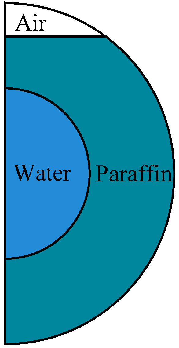
Figure 2.
The evolution of melting phase change material (PCM), represented by liquid fraction (left) and temperature contour (right), for the default configuration.
Figure 2.
The evolution of melting phase change material (PCM), represented by liquid fraction (left) and temperature contour (right), for the default configuration.

Figure 3.
Evolution of the melting fraction, mean PCM temperature, and mean water temperature for the default configuration.
Figure 3.
Evolution of the melting fraction, mean PCM temperature, and mean water temperature for the default configuration.

Figure 4.
The schematic of the LHS unit with varying eccentricity.

Figure 5.
Evolution of the performance parameters for varying eccentricity: (a) melting fraction; (b) exergy efficiency; (c) water temperature; (d) paraffin temperature.
Figure 5.
Evolution of the performance parameters for varying eccentricity: (a) melting fraction; (b) exergy efficiency; (c) water temperature; (d) paraffin temperature.

Figure 6.
The schematic of the shell-and-tube units for different inner tube diameters.
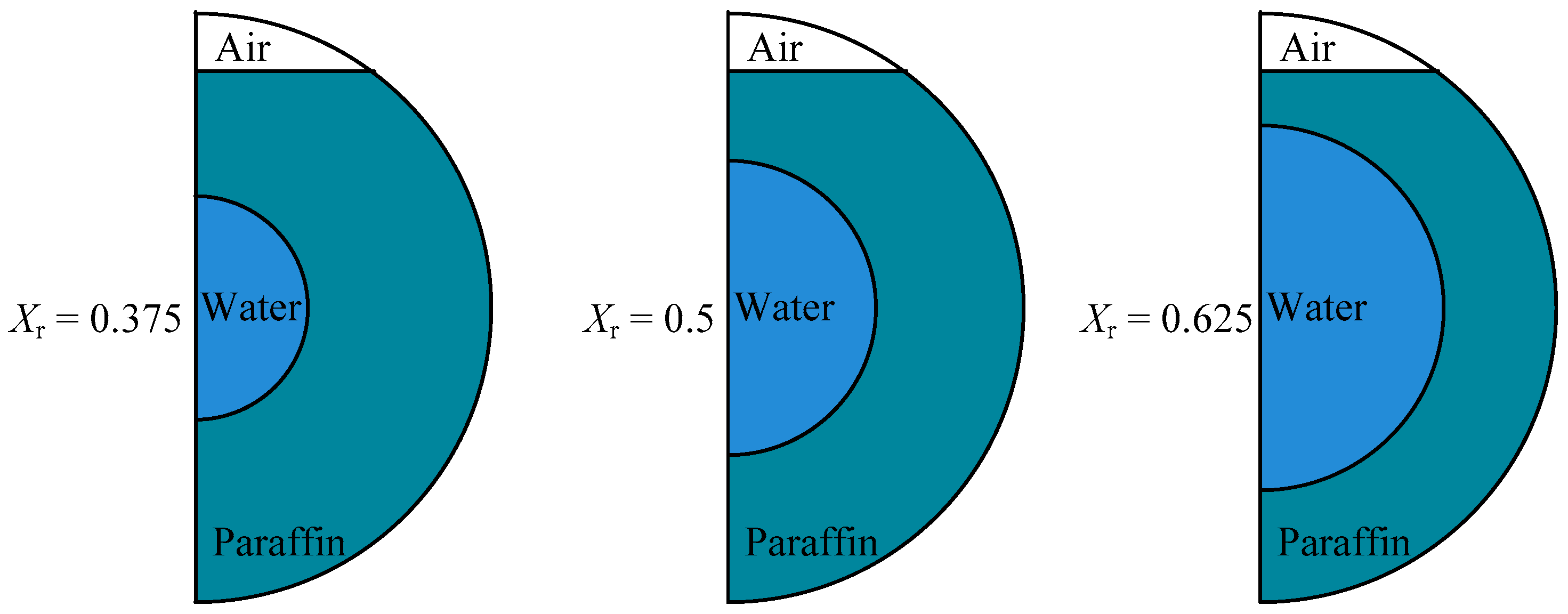
Figure 7.
Evolution of the performance parameters for varying inner tube diameter: (a) melting fraction; (b) exergy efficiency; (c) water temperature; (d) paraffin temperature.
Figure 7.
Evolution of the performance parameters for varying inner tube diameter: (a) melting fraction; (b) exergy efficiency; (c) water temperature; (d) paraffin temperature.
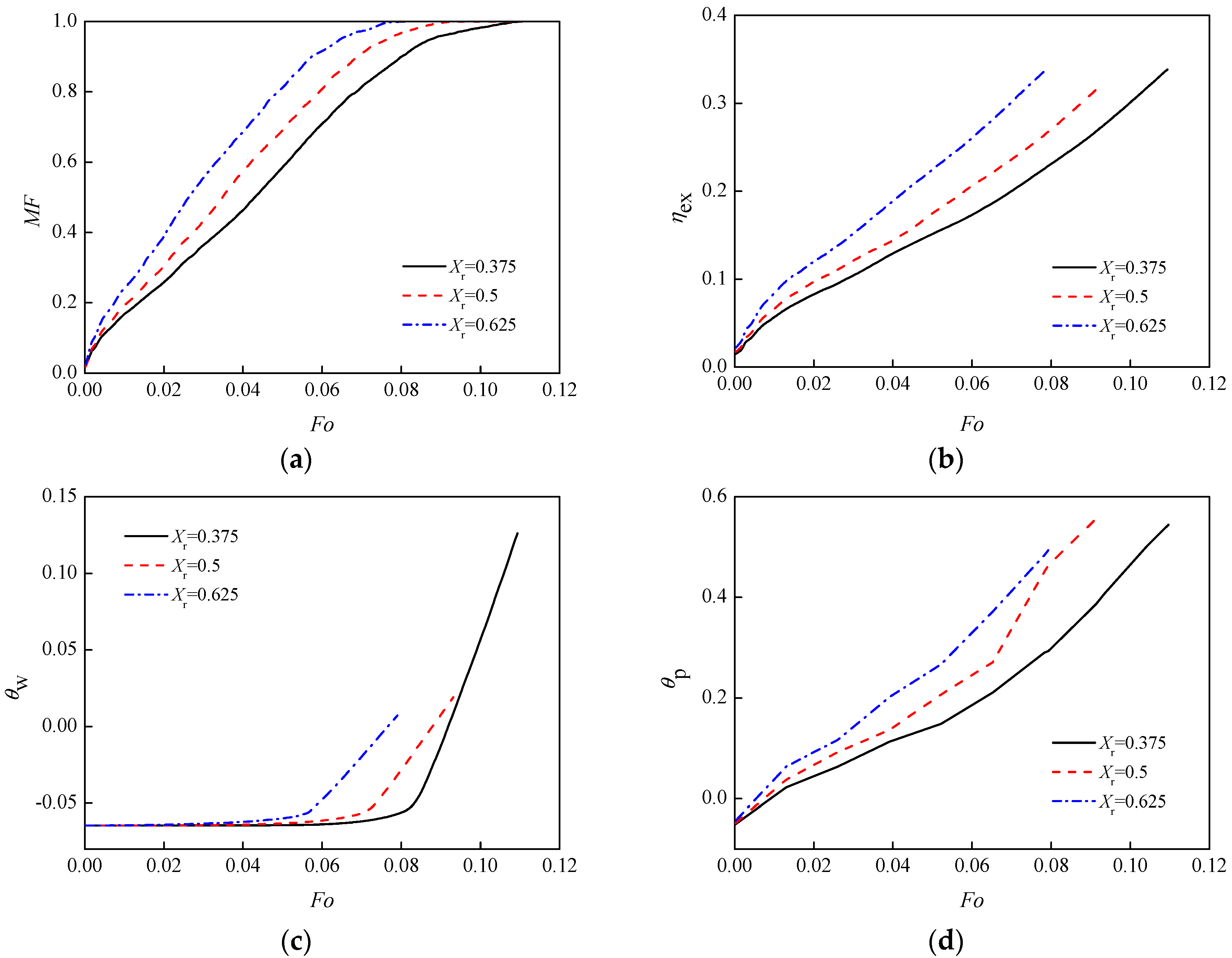
Figure 8.
Evolution of the performance parameters for varying Stefan numbers: (a) melting fraction; (b) exergy efficiency; (c) water temperature; (d) paraffin temperature.
Figure 8.
Evolution of the performance parameters for varying Stefan numbers: (a) melting fraction; (b) exergy efficiency; (c) water temperature; (d) paraffin temperature.
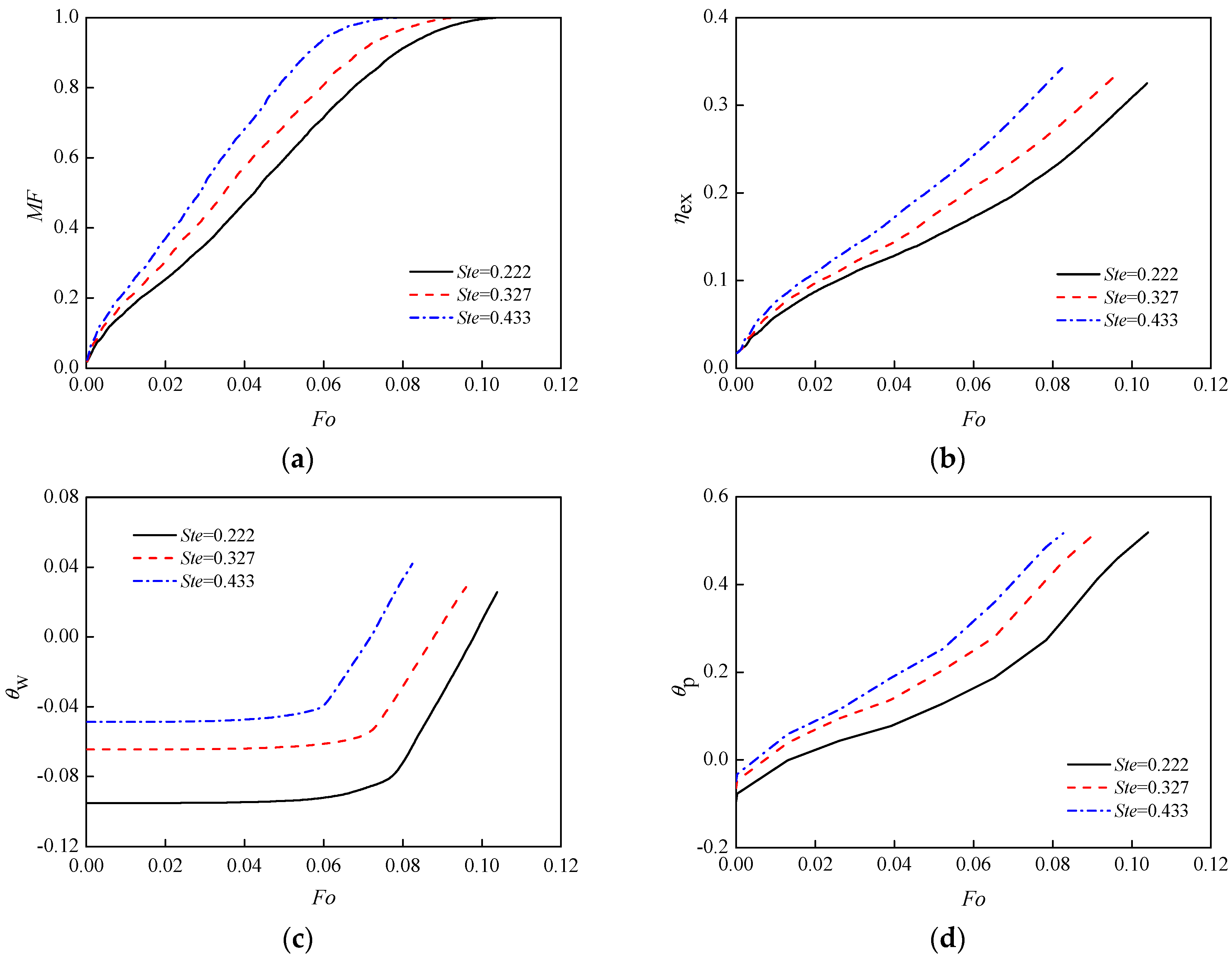
Figure 9.
Evolution of the performance parameters for varying degrees of sub-cooling: (a) melting fraction; (b) exergy efficiency; (c) water temperature; (d) paraffin temperature.
Figure 9.
Evolution of the performance parameters for varying degrees of sub-cooling: (a) melting fraction; (b) exergy efficiency; (c) water temperature; (d) paraffin temperature.

Table 1.
Thermophysical properties.
| Properties | Values | ||
|---|---|---|---|
| Solid PCM | Liquid PCM | Air | |
| density, kg/m3 | 870 | 760 1 | 1.225 2 |
| specific heat, J/(kg·K) | 2400 | 1890 | 1006.43 |
| thermal conductivity, W/(m·K) | 0.24 | 0.15 | 0.0242 |
| dynamic viscosity, Pa·s | - | 0.0032 | 1.789 × 10⁵ |
| volumetric expansion coefficient, 1/K | - | 0.0009 | - |
| latent heat, J/kg | - | 179,000 | - |
1 This value corresponds to that at temperature 301 K. 2 This value corresponds to that in the initial condition.
Table 2.
Parametric variables.
| Factors | Values | Dimensionless Form | Dimensionless Values | ||||
|---|---|---|---|---|---|---|---|
| inner tube center offset, mm | 0 | 5 | 7.5 | Xoff | 0 | 0.125 | 0.1875 |
| inner tube diameter, mm | 15 | 20 | 25 | Xr | 0.375 | 0.5 | 0.625 |
| shell temperature, K | 323 | 333 | 343 | Ste | 0.222 | 0.327 | 0.433 |
| initial temperature, K | 291 | 296 | 300 | Dsc | 0.116 | 0.063 | 0.021 |
© 2017 by the authors. Licensee MDPI, Basel, Switzerland. This article is an open access article distributed under the terms and conditions of the Creative Commons Attribution (CC BY) license (http://creativecommons.org/licenses/by/4.0/).
Share and Cite
MDPI and ACS Style
Li, S.; Chen, Y.; Sun, Z. Numerical Simulation and Optimization of the Melting Process of Phase Change Material inside Horizontal Annulus. Energies 2017, 10, 1249. https://doi.org/10.3390/en10091249
AMA Style
Li S, Chen Y, Sun Z. Numerical Simulation and Optimization of the Melting Process of Phase Change Material inside Horizontal Annulus. Energies. 2017; 10(9):1249. https://doi.org/10.3390/en10091249
Chicago/Turabian StyleLi, Saiwei, Yu Chen, and Zhiqiang Sun. 2017. "Numerical Simulation and Optimization of the Melting Process of Phase Change Material inside Horizontal Annulus" Energies 10, no. 9: 1249. https://doi.org/10.3390/en10091249
Note that from the first issue of 2016, this journal uses article numbers instead of page numbers. See further details here.