Achievement of Fuel Savings in Wheel Loader by Applying Hydrodynamic Mechanical Power Split Transmissions

State Key Laboratory of Mechanical Transmissions & School of Automotive Engineering, Chongqing University, Chongqing 400044, China
*
Author to whom correspondence should be addressed.
Energies 2017, 10(9), 1267; https://doi.org/10.3390/en10091267
Submission received: 5 July 2017
/
Revised: 16 August 2017
/
Accepted: 21 August 2017
/
Published: 25 August 2017
(This article belongs to the Section D: Energy Storage and Application)
Abstract
:The fuel economy of wheel loaders is deeply affected by the efficiency of their propelling transmissions, however, the torque converter (TC) in existing propelling transmissions is a low-efficiency component and leads to excessive energy consumption. Accordingly, this paper replaces the TC with a hydrodynamic mechanical power split transmission (HMPST) for improving the fuel economy of wheel loader. Based on probability similarity theory, the typical operating mode for the vehicles is constructed, which is used to evaluate the energy consumption performance of the selected solutions. The four reasonable solutions, which can be initially applied to wheel loaders, are selected from among the HMPSTs using the lever diagram. Furthermore, the comparisons on efficiency and loading characteristics between these four solutions and a prototype TC are conducted. The design optimization for all the four solutions is implemented, in order to find the optimal fuel saving solution relative to the prototype TC, and only one solution with pure power split can meet the constraints. Finally, a simulation model of the wheel loader powertrain is established for validating the effectiveness of this optimal solution. The results show that the optimized solution can effectively improve the fuel economy of wheel loaders compared to the prototype TC and provides a novel substitute for current technology.
1. Introduction
Wheel loaders are indispensable machines for the construction of infrastructure such as highways and in coal mining. The wheel loader operation is pretty repetitive and the vehicle is frequently exposed to large loads, leading to high fuel consumption [1]. Taking a five-ton class application as an example, the total fuel consumption each year can be as much as 25.6 tons (assuming the working times per day and per year are 8 hours and 200 days, respectively). Today the most common wheel loader powertrain arrangement is as displayed in Figure 1 [2]. The engine is required to supply energy to both the working hydraulics system and propelling transmission system, which allow the bucket to be manipulated and thrust the vehicle forward or backward, respectively.
In this architecture, the torque converter (TC) is a key element since it has the excellent vibration-damping and thoroughly self-adaptive performance which enable the engine to work robustly even though the vehicle is frequently subjected to variable loads. However, owing to the double energy conversion in the TC and high slip between two terminals that performance inevitably, results in high losses. The low efficiency of the TC is the main reason for the excessive fuel losses of wheel loaders [3]. With the increasing emphasis on fuel savings and emission reduction worldwide, these devices may hardly meet the future development trends [4]. Therefore, a substitute for the TC that improves the fuel economy of wheel loaders is essential.
The hydrodynamic mechanical power split transmission (HMPST) can be a desirable choice, since in it a part of the power is transferred by the mechanical branch and the rest is transferred through the TC [5,6]. With this special architecture, the HMPST simultaneously has a higher efficiency and retains most of the advantages of a TC. Furthermore, there is a possibility that the HMPST can enable the engine to work in the economical areas due to a wide variety of configurations available for HMPSTs. Therefore, in this paper, the HMPST is selected as the research subject.
HMPSTs comprise a TC and a planetary gear train (PGT). Many references have examined the basic characteristics of HMPSTs, providing comparative analyses for different configurations, as well as the design methods for HMPSTs. Wang et al. elaborated the operational principle of a new HMPST in a roadheader’s cutting unit. A dynamic model for such a transmission was constructed. The simulation results showed that both the vibration of the drive motor and the dynamic engagement force of the gears are substantially lessened compared to those of the prototype transmission when encountering pulse loads [7]. Jo et al. suggested a new input torque coupled HMPST concept, where the hydraulic elements were placed at both the mechanical and hydraulic branches. To evaluate the usefulness of the designed mechanism relative to a prototype TC (TC), the torque ratio and efficiency for all six schemes were analyzed using the performance locus diagram [8]. Linares et al. proposed a thorough methodology for designing a continuously variable power split transmission with several types of power flow suitable for an agricultural tractor. The objective of this study is to determine the design parameters for a general type of this transmission such as the transmission ratios of PGT, and the lockup point, which is the transition point between the hydromechanical transmission and the purely mechanical transmission [9]. Achtenova et al. developed a software for designing highly efficient HMPSTs with several mechanical speeds, which aimed at obtaining continuously variable transmissions with wide speed ratio ranges. Each speed was the combinations of a few PGTs, and its mechanical efficiency was calculated by the matrix method. The advantages of this code are the high integration and computational efficiency [10].
Other studies have concentrated on improving the performance of construction machinery using some types of HMPSTs. Zhao et al. implemented the design optimization for the crawler bulldozer equipped with a pure power split type of HMPST for increasing both the dynamic performance and fuel economy of the vehicle under a typical operating mode. These two objectives are achieved by the smaller TC diameter and less vehicle quality. However, the TC adopted in the HMPST is not based on the prototype TC. That is, the improvement of performance is not necessarily caused by the power split structure [11]. Wang et al. proposed a power reflux hydrodynamic transmissions (PRHTS) applied to the wheel loader. For constructing the optimal matching between the diesel engine and the PRHTS, the design optimization for the PRHTS was conducted, which was based on the radar chart and genetic algorithm. However, a simulation model for the wheel loader powertrain system was not constructed, so whether the performance of the vehicle is increased needs to be justified. Moreover, such a transmission is only one type of HMPST and its rationality relative to other schemes requires to be verified as well [12].
The objective of this paper is to improve the fuel economy of a wheel loader by applying the HMPST concept, which is rarely researched in previous works. In view of this, a design methodology for such a transmission is necessary. Moreover, considering the relatively complex construction of HMPSTs, the simplest form, which consists of a TC with three components and a single PGT, is adopted here.
In this paper, there are two critical issues to be dealt with. One is the preliminary selection of the the HMPST options. Since HMPSTs have a number of different schemes, if a design optimization for all the schemes is conducted, it is bound to cause a high calculation cost. The subsequent comparison analysis between each scheme can be hardly justified. This issue will be solved in Section 3. Furthermore, the TC in the HMPSTs has to be based on the prototype, i.e., only the effective diameter of the TC can be altered. Only in this way a comparison between HMPSTs and a prototype TC can make sense.
The other is the construction of an optimization model. Although the HMPST efficiency is the key factor influencing the fuel consumption of a wheel loader, it is not the only one. The engine efficiency is also an option. The ideal fuel saving solution provided by HMPSTs is that they have a higher efficiency and can enable the engine to work in the most economical area. However, the HMPST is a self-adaptive mechanism and thus it cannot actively control the engine to work in a specified areas. On the other hand, the wheel loader operation is highly repetitive, that means the general operating mode of wheel loaders can be predicted and modeled [3,13]. Considering these two aspects, this paper optimizes HMPSTs using some features of the typical operating mode, in order to find the optimal fuel saving potential solution for HMPSTs.
The rest of paper is arranged as follows: an operating mode for a wheel loader is constructed in Section 2. Section 4 implements the design optimization for the selected HMPSTs, where the objective function is the fuel saving potential relative to the prototype TC. After the results are obtained, a simulation to determine the optimal solution is conducted in the Matlab/Simulink environment, in order to verify the effectiveness of the constructed optimization model.
2. Operating Mode and Instantaneous Fuel Consumption
The total fuel consumption that a wheel loader expends in a task is the time integral of its instantaneous fuel consumption. The instantaneous fuel consumption is the product of engine output power, the fuel consumption rate of the engine and unit time [14]. In view of this, first, an operating mode that presents the power requirements for the typical working manner of wheel loader is constructed. Second, the variables which influence the instantaneous fuel consumption of vehicle are analyzed. Third, the loading characteristics of the TC is derived, which is used to determine the working points of the TC and engine under external loads.
2.1. Operating Mode
To evaluate the performance of a wheel loader such as the working time cost, loading material volume and fuel consumption, a definite operating mode is required to describe the power requirements for the typical working manner of the wheel loader [3,13]. The most common working manner for a wheel loader is the V-type route that consists of five segments [15,16]. That is, the operator implements the task repeatedly according to the V-type route. In the first segment, the vehicle drives towards the material piles until it reaches the destination. During the second segment, the bucket is inserted into the material piles by the great driving force provided by the propelling transmission system, then the operator manipulates the bucket and boom in an almost synchronous and continuous manner. After this process is repeated several times, the bucket can be filled up. In the third segment, the vehicle returns back to the initial position. In the fourth segment, the operator turns the vehicle towards the transport while lifting the bucket to a certain height. The unloading of the material is mainly completed by the tilt action, which controls the rotation motion of the bucket. After the material is delivered to the transport, the vehicle goes back to the initial position according to the route of Segment 4. One complete procedure for this working manner is shown in Figure 2.
A-five-ton class wheel loader is the objective vehicle in this study, as shown in Figure 3. The basic parameters of this vehicle are listed in Table 1. For obtaining the real-time working state of vehicle, testing transducers are placed at the designated positions, which are indicated by the Arabic numerals in Figure 1. The measurement variables of the transducers are the input and output angular speeds of the TC, pressure of the hydraulic pump, rotation angles of the boom and bucket cylinders, and output angular speed of the mechanical gearbox. The vehicle is manipulated by an expert driver, and its working manner is based on the V-type route shown in Figure 2. The objective material piles are raw soil, and the working cycle times of the vehicle are fifty. Since the fifty sets of data collected directly by the testing transducers contain many noise signals and also cannot present the power requirements of the wheel loader, they have to be further converted into the operating mode of wheel loader, which can be used for the off-line simulation and evaluation of the wheel loader.
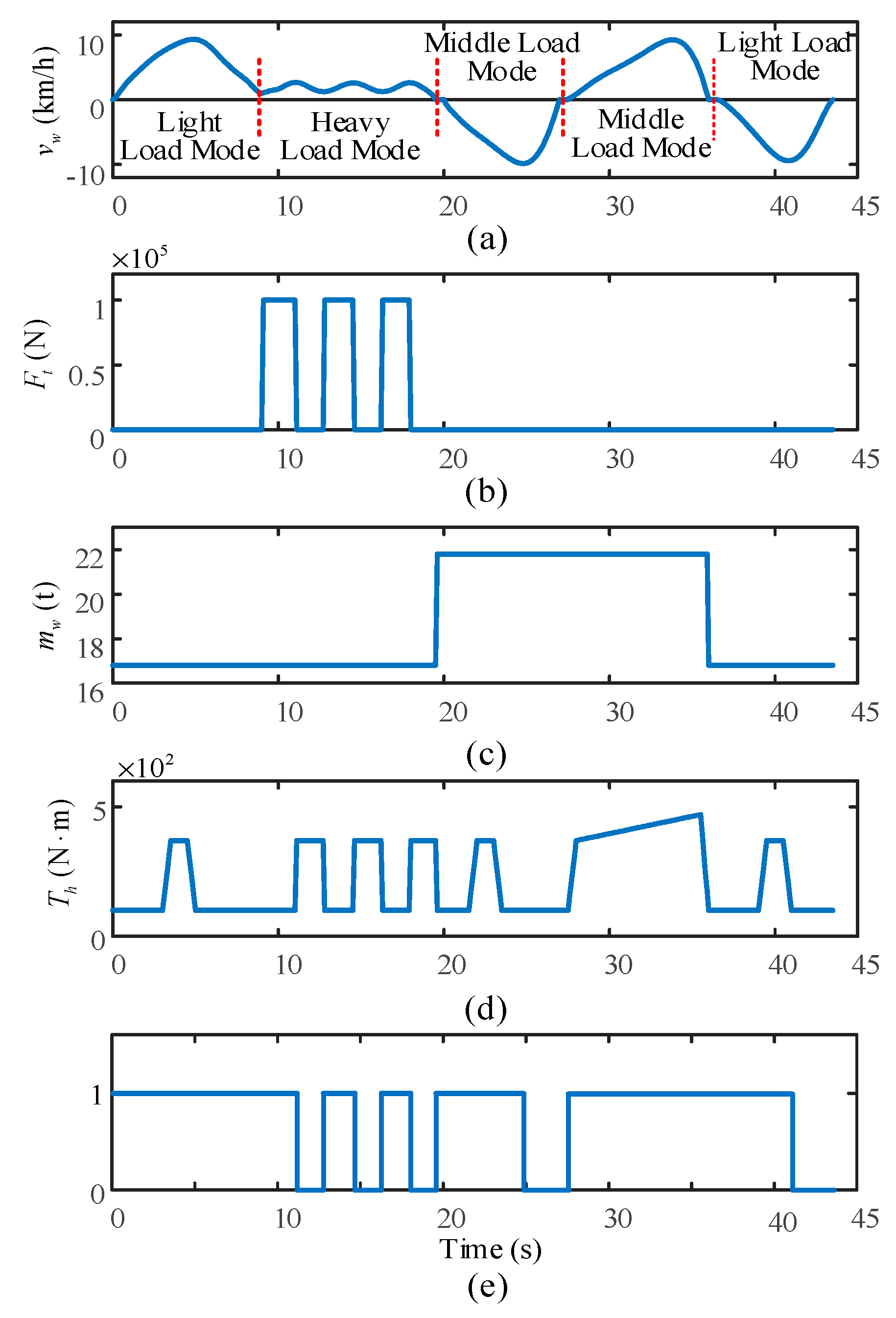
Generally, a data processing method based on probability similarity theory is used to construct the operating mode of wheel loaders due to the fact that it can extract the feature data from raw data correctly while reproducing the energy consumption features in both the simulation environment and experiments [17,18]. Therefore, the operating mode of a wheel loader, which consists of the vehicle velocity , thrusting resistance , whole vehicle mass , and load torque of hydraulic pump , is derived through this method. Moreover, both the lateral dynamics of vehicle and wheel slippage are ignored in this derivation, since this study focuses on the longitudinal dynamics of the vehicle. Similar assumptions can be found in [3,19]. Figure 4a–d present the typical operating mode of this wheel loader. It can be seen that based on the different working states of the wheel loader, the load modes of its engine can be classified into three types, which are the light, the medium and the heavy type. At the light load mode, the engine outputs a low power, which is used to overcome the driving resistance. In medium load mode, additional power is required to shift the working unit. In the heavy mode, the engine almost outputs the rated power, which is used to both overcome the insertion resistance and lift the bucket with full loads. The corresponding load mode of each segment is depicted in Figure 4a. Figure 4e presents the division of engine power between the propelling transmission system and working hydraulics system. The 1 indicates that the engine outputs power to both branches, and the 0 indicates only the hydraulic branch absorbs energy from the engine.
2.2. Analysis of Instantaneous Fuel Consumption
According to the above, the instantaneous fuel consumption of wheel loader is:
where is the engine output power, is the fuel consumption rate of engine, t is the unit time, equal to one second.
During the operation of the vehicle, the engine output power is divided into two parts. One is transferred to the working hydraulics system, which controls the working unit to perform shoveling operations. The other is transferred to the propelling transmission system, which is used to overcome the driving resistance. The ratio of engine speed to hydraulic pump speed is 1 in the introduced wheel loader. According to the transfer path of engine output power and dynamics of vehicle propelling transmission system, the following expressions can be derived:
where and are the input power of the propelling transmission system and working hydraulics system, respectively, and are the input torque of wheels and working hydraulics system, respectively, and are the angular velocities of engine and wheels, respectively, and are the total efficiencies and speed ratios of mechanical gearbox, final drives and wheel reducers, respectively, and are the efficiency and speed ratio of TC, respectively.
The fuel consumption rate of engine is the inverse proportional function of engine efficiency [20]. Moreover, the engine efficiency is the function of output torque and engine speed :
where is the engine efficiency, k is the fuel constant, is the torque ratio of TC.
The instantaneous fuel consumption is rearranged by substituting Equations (2)–(4) into Equation (1):
Equation (5) shows that the instantaneous fuel consumption of vehicle is a function of the engine efficiency, speed ratio and efficiency of TC under the constructed operating mode. Therefore, the higher the three variable factors, the lower the instantaneous fuel consumption of the vehicle.
2.3. Loading Characteristics of Torque Converter
Equation (4) shows that the working points of the engine only depends on the torque ratio and speed ratio of the TC. Moreover, the TC itself is the key component dominating the fuel economy of a wheel loader. Hence, in this section, the loading characteristics of the TC are analyzed. The pump torque capacity coefficient of TC is [21]:
where and are the pump torque and speed, respectively, is the pump torque coefficient, is the fluid density, g is the gravitational acceleration, and D is the effective diameter of TC circuit.
Similarly, the turbine torque capacity coefficient of TC can be defined as:
where and are the turbine torque and speed, respectively.
Based on the turbomachinery principles, all the torque ratio, efficiency and pump torque coefficients of the TC are univariate functions of the speed ratio [22]. As a result, the turbine torque capacity coefficient is a univariate function of the speed ratio as well. Equation (7) expresses the relationship between speed ratio and external loads effected on the output terminal of the TC, which is treated as the loading characteristics of the TC. The solid curve in Figure 5 displays the loading characteristics of a prototype TC. It can be observed that the speed ratio increases monotonically with the increase of turbine torque capacity coefficient. As long as the external loads are known, both the speed ratio of the TC and working points of the engine will be uniquely determined. The whole speed ratios of TC for the constructed operating mode are calculated, and subsequently imported into Figure 5. This figure shows that at the heavy engine load mode, the corresponding speed ratios of the TC are considerably low, which matches with a low efficiency area of the TC. As a result, its instantaneous fuel consumption is the highest among the three types of modes.
From the above, it can be concluded that the reasonable load characteristics of a TC should be matched well with the external loads. Otherwise, the external loads will not be able to load the TC effectively, and consequently this TC cannot be applied in a wheel loader. The TC indicated with the dotted curve in Figure 5 is unreasonable, since there are no working points on this TC for the Segment 1 and 5 of the constructed operating mode.
3. Initial Selection and Analysis for the HMPSTs
Since a lot of different HMPST configurations exist, the analysis and design for all these configurations would be a cumbersome task for an industrial designer. To avoid such a problem, this section firstly selects the most reasonable schemes from within the possible HMPSTs which can be initially applied to a wheel loader. Then the comparisons between the basic characteristics of each solution and that of the prototype TC are carried out, in order to get a clear understanding of these solutions.
3.1. Initial Selection
The HMPST mainly consists of a TC and a single PGT. According to the different features for the torque transferred by the two terminals of a HMPST, the HMPST can be divided into two types: the input torque coupled architecture and output torque coupled architecture, as shown in Figure 6. The R, C and S denote the ring gear, the planet carrier and sun gear, respectively. The P, T and G denote the pump, the turbine and stator, respectively. In the input torque coupled HMPSTs, there are six basic schemes based on the connections of the input shaft of HMPST and the turbine to the three components of the PGT. Considering the TC can be inversely placed at the hydraulic branch, six additional schemes are possible for this architecture. Similarly, the output torque coupled HMPSTs also have 12 schemes, so there are 24 HMPST schemes in total.
Whether the HMPSTs can be applied to the wheel loader or not depends on both the working form of the TC and the power flows in the system. Since the TC can only work well in the first quadrant, the schemes that cannot meet this condition will deteriorate the working performance of wheel loader and have to be eliminated. Furthermore, the schemes that exist following two types of power flows have to be eliminated as well. One is that the power is transmitted from turbine to pump, the other is that the input power of TC is higher than that of system. The efficiencies of these two types are always lower than that of the prototype TC, which results in them lacking any practical value.
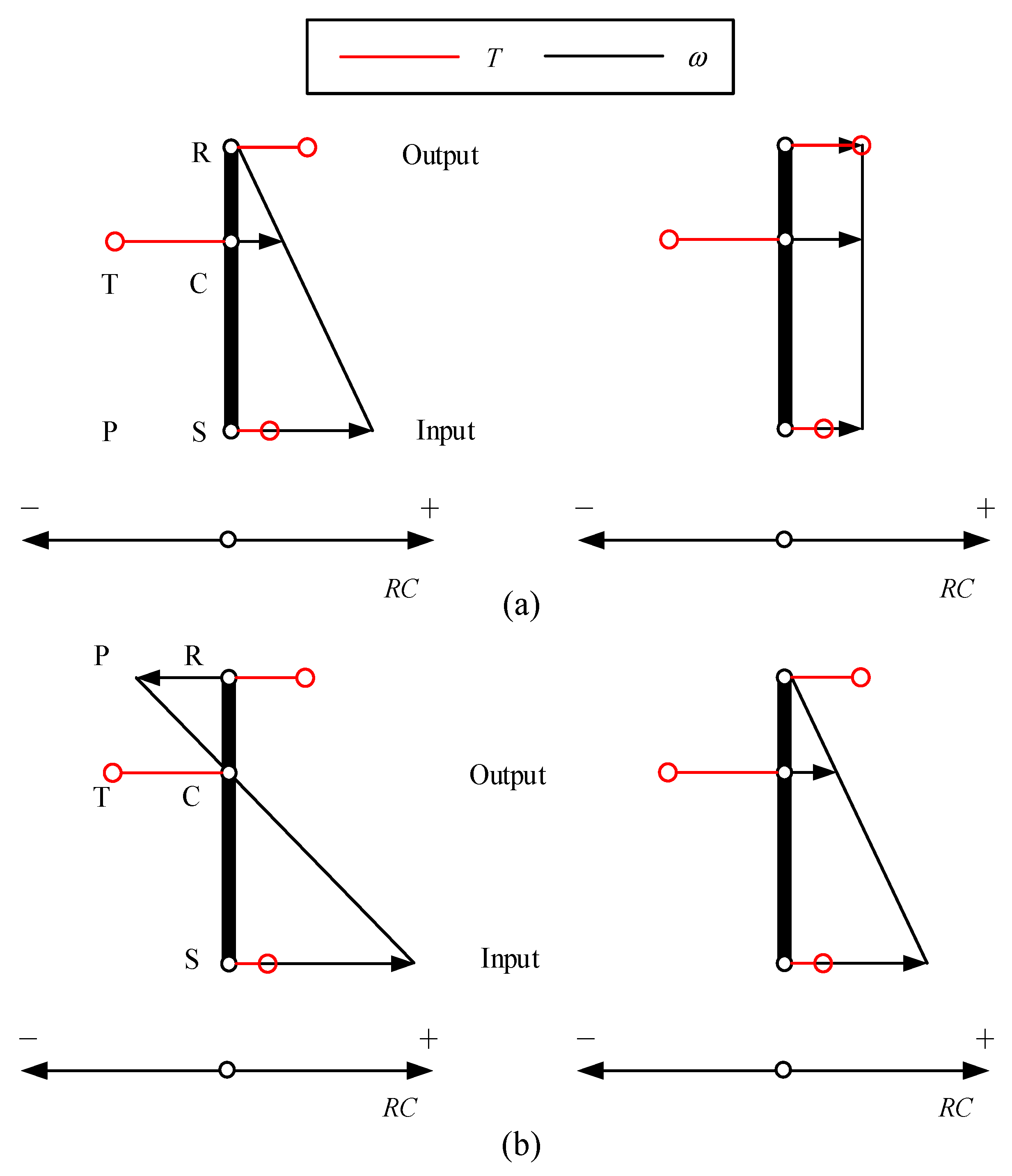
The reasonable HMPST schemes are selected by the lever diagram, since it can visualize both the power transfer path of the mechanism and the kinematic relationships between each link based on the torque equilibrium of all terminals and conservation of energy [23,24]. The lever diagram for Figure 6a is shown in Figure 7a, where the RC is the reference coordinate system, and the circle and arrow indicate the direction of the torque T and speed , respectively. It can be observed that as the speed of the ring gear increases from the stall state, and the three components of the PGT rotate simultaneously in the same direction, which means that the TC always works in the first quadrant. However, the power transferred by planet carrier is the sum of that transferred by the ring gear and sun gear, which indicates that the sum of HMPST input power and the recirculating power passes through the TC with low efficiency. Consequently, this scheme should be rejected. The discriminant method for the scheme in Figure 6b is presented in Figure 7b.
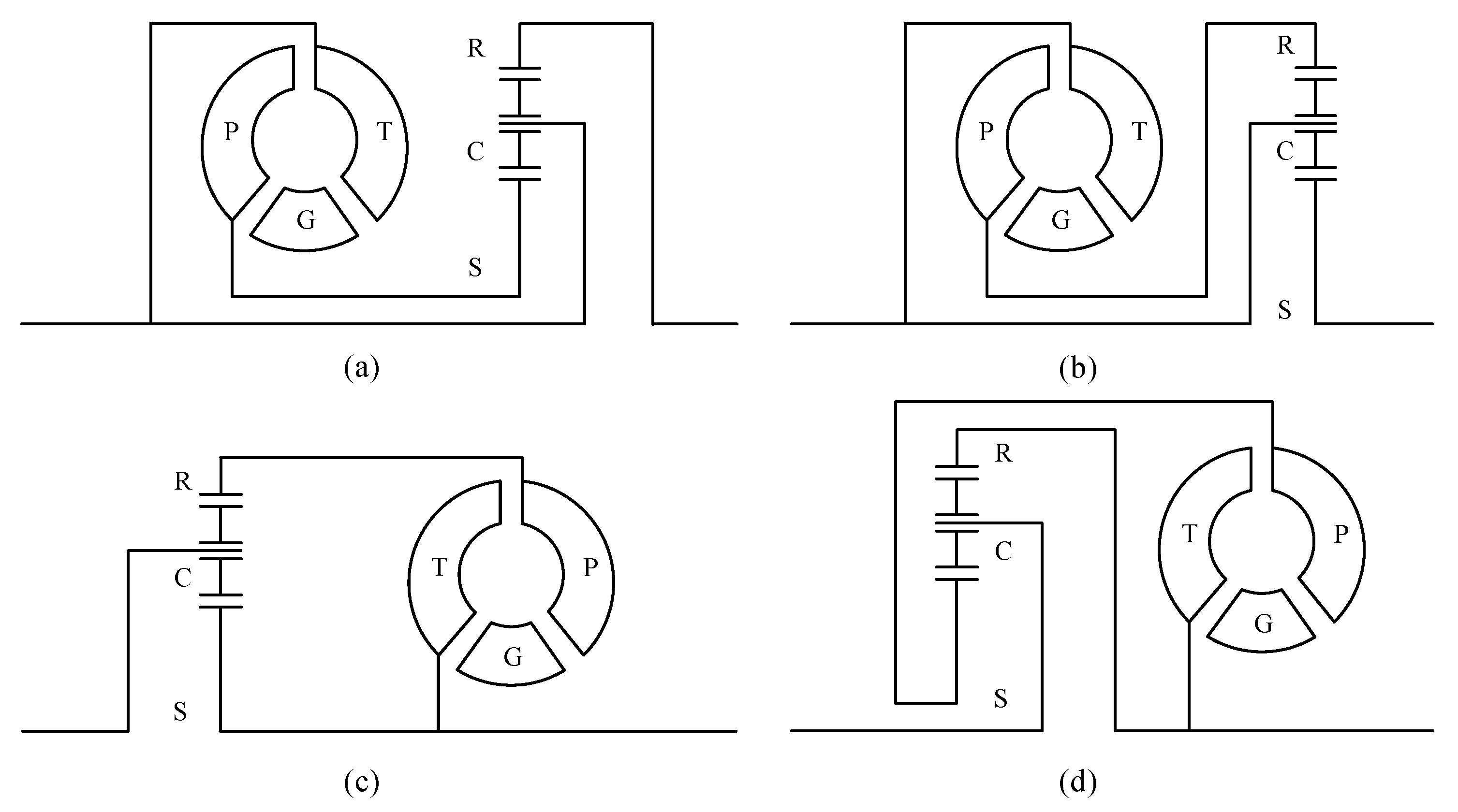
The ring gear rotates in the opposite direction relative to the planet carrier while the planet carrier speed increases from zero to a certain value, which means that the pump and turbine rotate in opposite directions, and the TC works in the second quadrant. As a result, this scheme has to be rejected as well. Similarly, the remaining 22 schemes are judged by this method. Figure 8 shows the four ultimately reasonable solutions for HMPSTs.
3.2. Basic Characteristics Analysis
As the TC is embedded in the HMPST, each of above four solutions is equivalent to a certain type of TC. The basic characteristics of the HMPSTs comprise efficiency and loading characteristics . The derivation for these basic characteristics are based on the steady state and the PGT efficiency treats as the constant [25,26]. According to the torque equilibrium of PGT, energy conservation and known power flow of each solution, the basic characteristics of each solution can be derived as:
where m (m = a,b,c,d) denotes the four solutions in Figure 8, is the structural parameter of the PGT, which is the ratio of the numbers of ring gear teeth to that of sun gear teeth, i is the HMPST speed ratio and equal to the ratio of output speed to input speed.
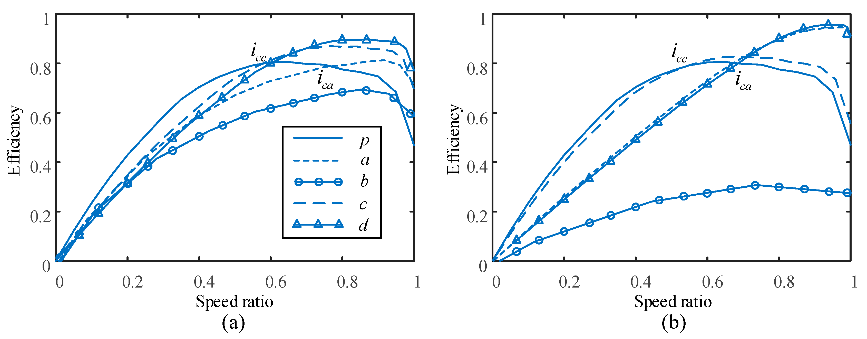
Equation (8) shows that the variable factors influencing the basic characteristics of each solution are the structural parameter of the PGT and the effective diameter of the TC circuit D. By further analysis, it is found that the efficiency varies strictly monotonically with and D. Therefore, the two boundary values for the and a specific value for the D are adopted to examine the basic characteristics of each solution.
Figure 9 shows the efficiency of each solution. The term p denotes the prototype TC. For solution a, its efficiency can gain a significant advantage over the prototype when the speed ratio is greater than about 0.65. Figure 4 and Figure 5 show that the engine works in the light load mode in this range. However, in the low speed ratio range, the engine outputs higher power. That means the proportion of fuel consumption for low speed ratio range are greater than that for high speed ratio range among the total fuel consumption. Due to the oversized , the deficiency of efficiency in the low speed ratio range can hardly be made up by advantage of efficiency in the high speed ratio range. For solution b, its efficiency is much less than that of prototype in the entire range of . For solution c, the efficiency integral area of such a solution is slightly greater than that of the prototype. The decreases with the increase of , which facilitates the improvement of fuel economy of vehicle in the low speed ratio range. As for the solution d, it displays a similar situation to solution a.
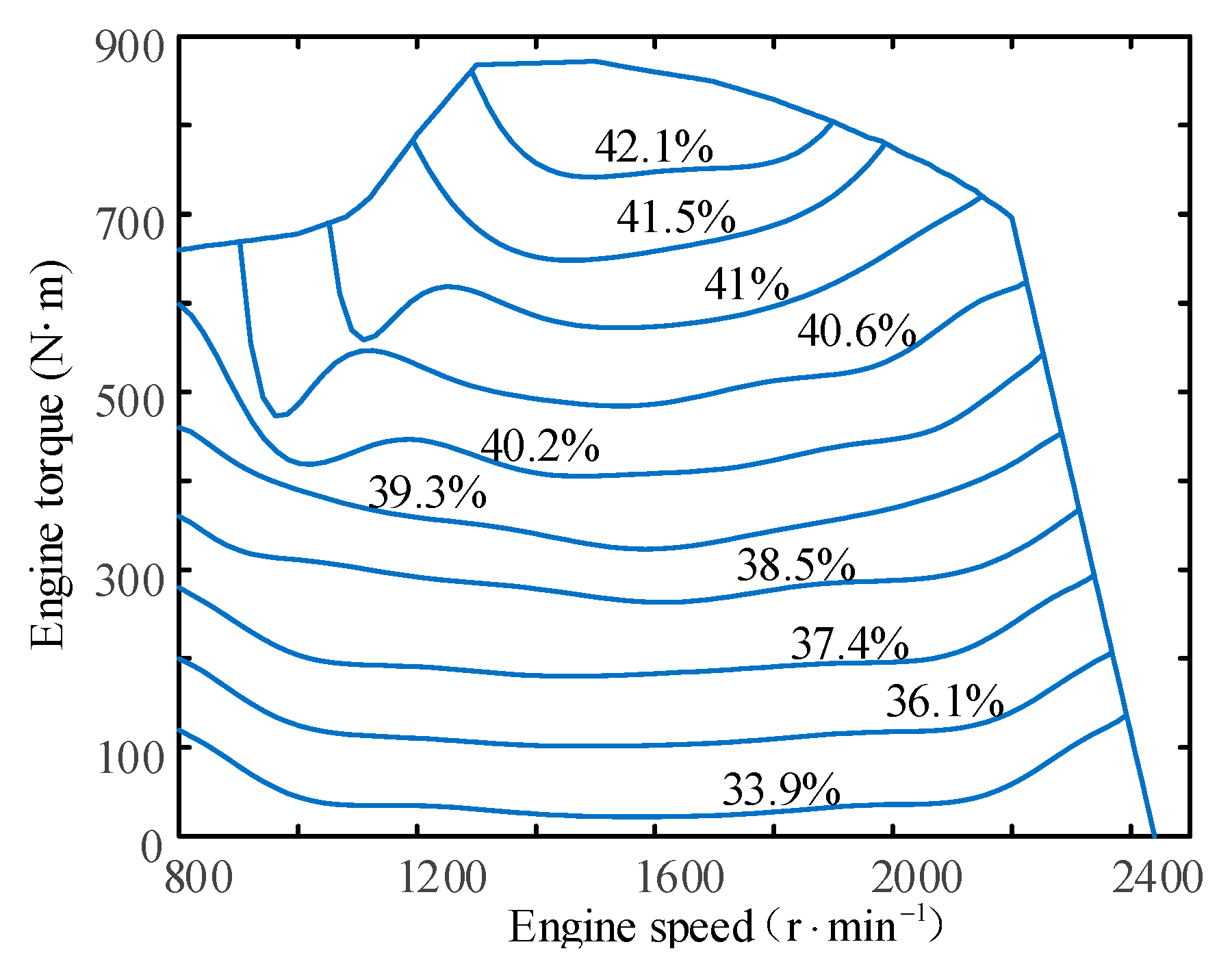
Figure 10 shows the loading characteristics of each solution. For the solution with characteristic curve above the prototype TC, it can achieve larger speed ratio at the same abscissa values. That means the engine can work at a smaller speed, and consequently the engine efficiency is increased. However, the change rate of speed ratio for this solution is greater than for the prototype. As a result, the working points of the engine will fluctuate in a larger range with the variation of external loads. Excessive transient conditions of engine are not conducive to improving the engine efficiency. Moreover, the solutions a and d cannot be applied to the wheel loader as the τ increases nearly to 5, since they cannot match well with the external loads. In a word, the ideal curve of each solution should approach that of the prototype and make the engine work in the economical areas simultaneously. Figure 11 presents the engine efficiency map for this study.
4. Design Optimization of Each Solution
In this section, the design optimization for each preliminary solution derived from the above is implemented, which aims at minimizing the fuel consumption caused by the engine and HMPST losses. At this point, first the optimization problems are put forward, where the objective functions are the fuel saving potential of each solution relative to the prototype TC. Then these problems are solved by the enumeration algorithm. Both the design optimization problem and technique for each HMPST solution are the same since it is equivalent to a certain type of TC.
4.1. Optimization Problems
4.1.1. Objective Functions
The fuel consumption of a wheel loader, which was discussed rigorously in the previous section, is dominated only by the engine efficiency, speed ratio and efficiency of the HMPST. At any moment, if each of these three factors obtained by the HMPSTs is greater than the corresponding factor obtained by the prototype TC, then the instantaneous fuel consumption will be naturally reduced. The above conception can be embodied by the following expression:
where is the engine efficiency for wheel loader using prototype TC at the moment of , and are the efficiency and speed ratio of prototype TC, respectively, is the engine efficiency for wheel loader using each solution of HMPSTs at the moment of , and are the efficiency and speed ratio of each solution of HMPSTs, respectively.
Furthermore, the transmission types of engine output power have to be weighed, since a portion of the engine output power is used to thrust the vehicle itself while the rest is taken to implement the working task. In view of this, the two weighting coefficients on the two legs of power are added to Equation (9). At any moment, the fuel saving potential for the wheel loader using each solution of HMPSTs relative to that using the prototype TC can be derived:
where and are the weight coefficients for the propelling transmission system and working hydraulics system, respectively.
Existing studies show that the ratio of average input power of the propelling transmission system to that of the working hydraulics system is about 1.5 [15,18], so the relationships between and are given as follows:
In every working segment, the total fuel saving potential for the HMPSTs is the time accumulation of Equation (10). In order to display the pros and cons of each solution of HMPSTs relative to the prototype TC clearly, the further normalization is conducted:
where Ni is the number of sampling points for each working segment (i = 1, 2, … 5).
Figure 4 and Figure 5 present that each load mode of engine differs greatly in the output power level, so in the light load mode, the engine output power is much lower than the rated power. In the heavy load mode, the engine works near the rated power point so that the considerable inserting resistance can be overcome. Therefore, the contribution of each load mode to the total fuel consumption is different. By incorporating the corresponding weighting coefficient into Equation (12), the total fuel saving potential for the HMPSTs under general working manner is obtained as below:
where is the weighting coefficient for each working segment. Here, is subjected to the lucid assumptions:
4.1.2. Design Variables
Considering this study focuses on improving the fuel economy of a wheel loader using a HMPST, the design variables for the optimization problem are the structural parameter of the PGT and the effective diameter of the TC circuit, which satisfy the following inequalities:
4.1.3. Constraints
The engine output torque has to meet the requirements of both the driving and the working as the wheel loader performs a task. Accordingly, the sum of the input torques for these two systems should not exceed the torque of the engine external characteristics :
where and are the input torques of the propelling transmission system and working hydraulics system, respectively.
Moreover, the torque load characteristics of the HMPST’s input terminal at zero speed ratio is important since the wheel loader has to overcome a heavy load at stall state. The intersection between the torque load curve of the HMPST’s input terminal at zero speed ratio and the engine external characteristic curve should be located between the point of maximum torque and that of engine rated power :
where is the engine speed corresponding to engine external characteristic curve, is the equivalent pump torque coefficient of the HMPST at zero speed ratio.
4.2. Optimization Algorithm
As for the design optimization for each HMPST solution, the number of objective functions and design variables is one and two, respectively. That means the optimization problems can be solved by a less-intelligent algorithm. In this study, the enumeration algorithm is used to solve these problems. The concrete solving flow chart for each solution is presented in Figure 12. All the implementation of these procedures are realized in Matlab 2015b (The MathWorks, Natick, MA, USA).
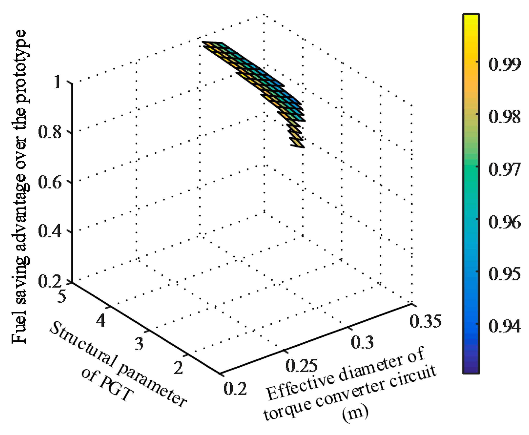
Figure 13 shows the solutions for scheme c while the other three schemes cannot find any solution less than 1, which indicates schemes a, b, and d cannot show fuel saving advantages over the prototype TC and have to be eliminated. It can be seen that the solutions mainly gather in the areas where the effective diameter of the TC circuit D is large. The reason is that the solution c with small D can achieve a low speed ratio relative to the prototype for the same turbine torque capacity coefficient. Even if at the same speed ratio of low speed ratio area, the efficiency of solution c is less than that of the prototype, so the lower speed ratio will reduce the efficiency of solution c further. At this point, the HMPST cannot gain fuel saving advantages over the prototype. The optimal solution for scheme c is 0.93 and the corresponding design variables are [2.73 0.31].
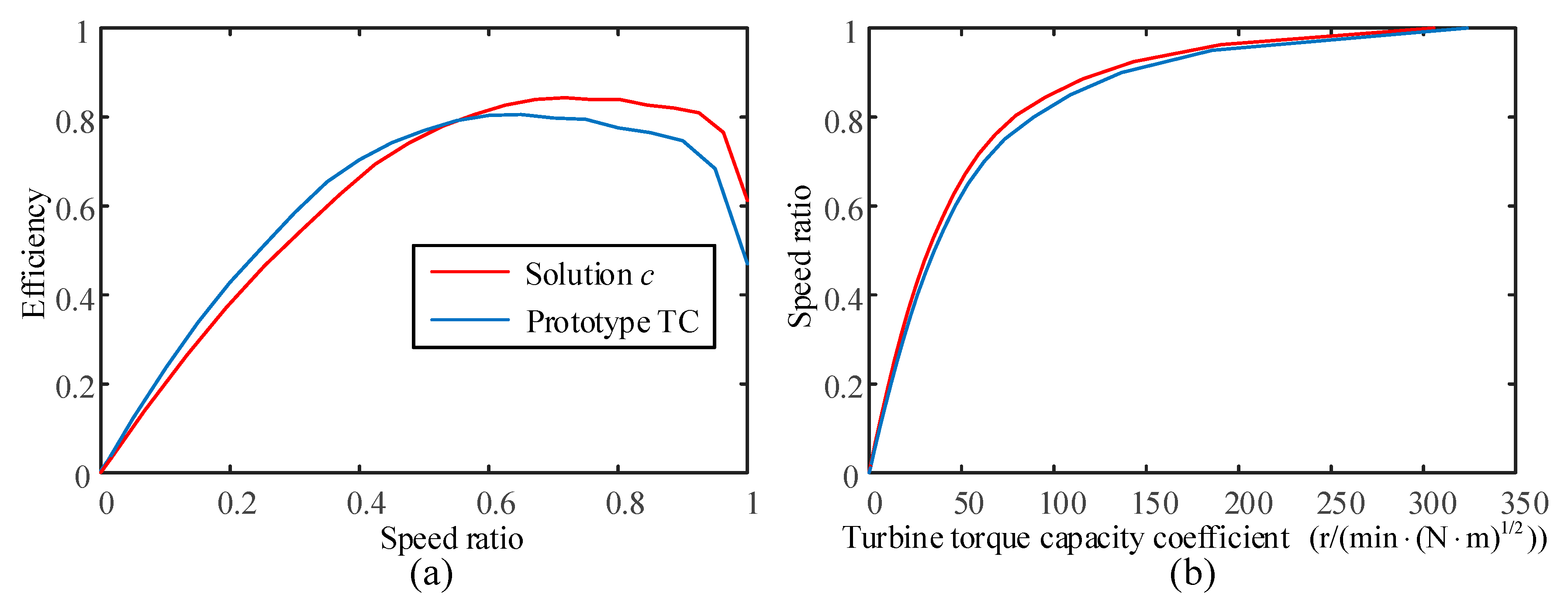
Figure 14 and Figure 15 show the architecture and basic characteristics of solution c with the optimal structural parameters, respectively. Compared with the prototype TC, the optimized solution c can gain advantage in the global speed ratio range due to the fact that its higher efficiency in the high speed ratio range, and its improvement of engine efficiency can counteract the deficiency of efficiency in the low speed ratio range.
5. Simulation and Analysis
5.1. Simulation Model
In order to verify the effectiveness of solution c with the optimal structural parameters, it is essential to build a simulation model that can imitate the behavior of a wheel loader according to the constructed operating mode. As this study is solely interested in the fuel consumption of wheel loaders, the detailed working state of each element such as the engagement process of the clutch during shifting and the boom rotating angle, can be ignored while constructing the simulation model. For that reason, the backward programming method is adequate for such a job [19,24]. The principle of the backward programming method is calculating the input torque and speed of each element according to the known output power variables. By implementing the calculation from the downstream to the upstream step by step, the total fuel consumption can be derived. The modellings for both the wheel loader using the solution c of HMPSTs and that using prototype TC are performed in the Matlab/Simulink environment.
The simulation procedures for both models are stated below. Firstly, the operating mode of wheel loader is divided into two types: the mechanical (the vehicle speed, thrusting resistance and whole vehicle mass) and the hydraulic (the load torque of hydraulic pump). All the mechanical components in the propelling transmission system are treated as the inertia element. The output torque and speed of mechanical gearbox are calculated from the mechanical variables based on the vehicle system dynamics. Secondly, the input torque and speed for the solution c of the HMPSTs or TC are derived by the shifting control strategy and the loading characteristics. Finally, the hydraulic variable is added to the input torque of the solution c, so the engine torque and speed are obtained. Thus, the whole simulation is completed.
5.2. Results Analysis
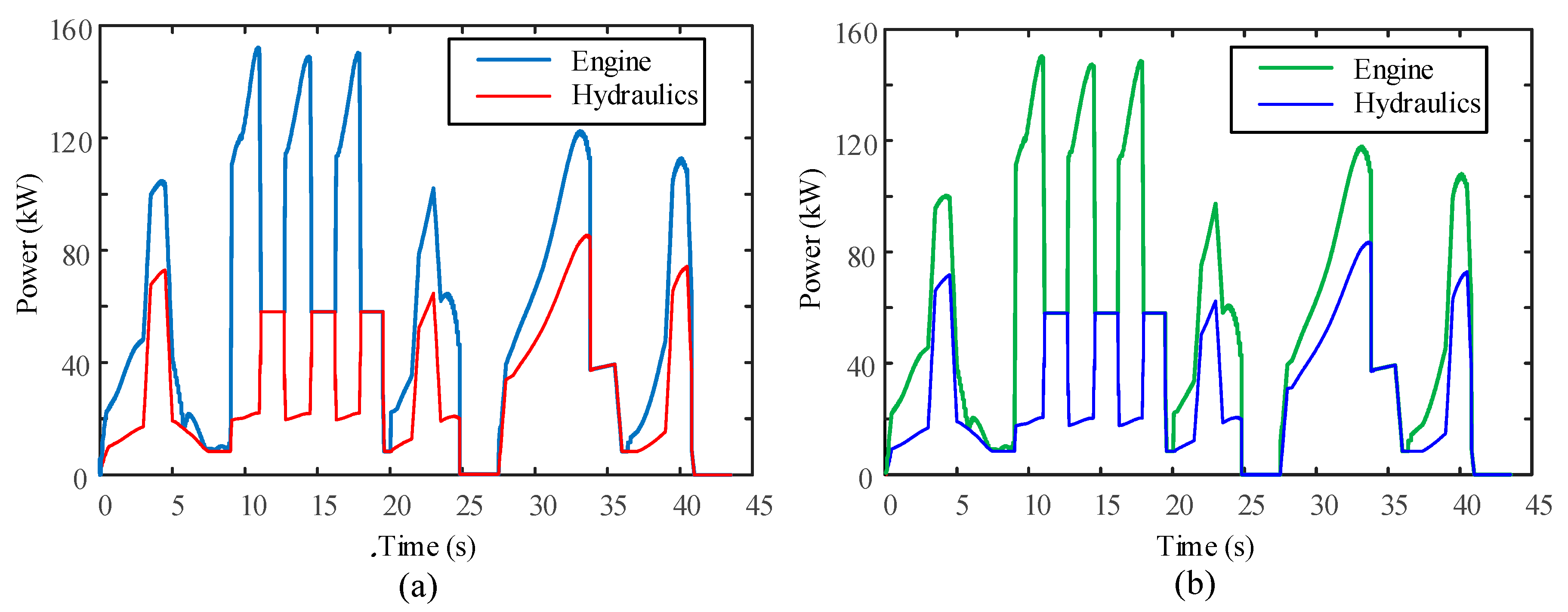
In this section, the simulations for the wheel loader using solution c for the HMPST and that using the prototype TC are implemented, respectively. Figure 16a,b present the load power of the engine and working hydraulics system for the prototype TC and the solution c of the HMPST, respectively. As for the wheel loader equipped with TC, the engine speed depends primarily on the loading characteristics of the TC. The principle of cooperation between the driving and working is to ensure that the hydraulics work robustly and consume less energy, simultaneously. The load power of the engine for the prototype TC is slightly greater than that of the solution c when the vehicle speeds up nearly to the peak. The reasons are that both schemes work at the high speed ratio areas, and the efficiency of solution c is higher than that of the prototype TC in these areas.
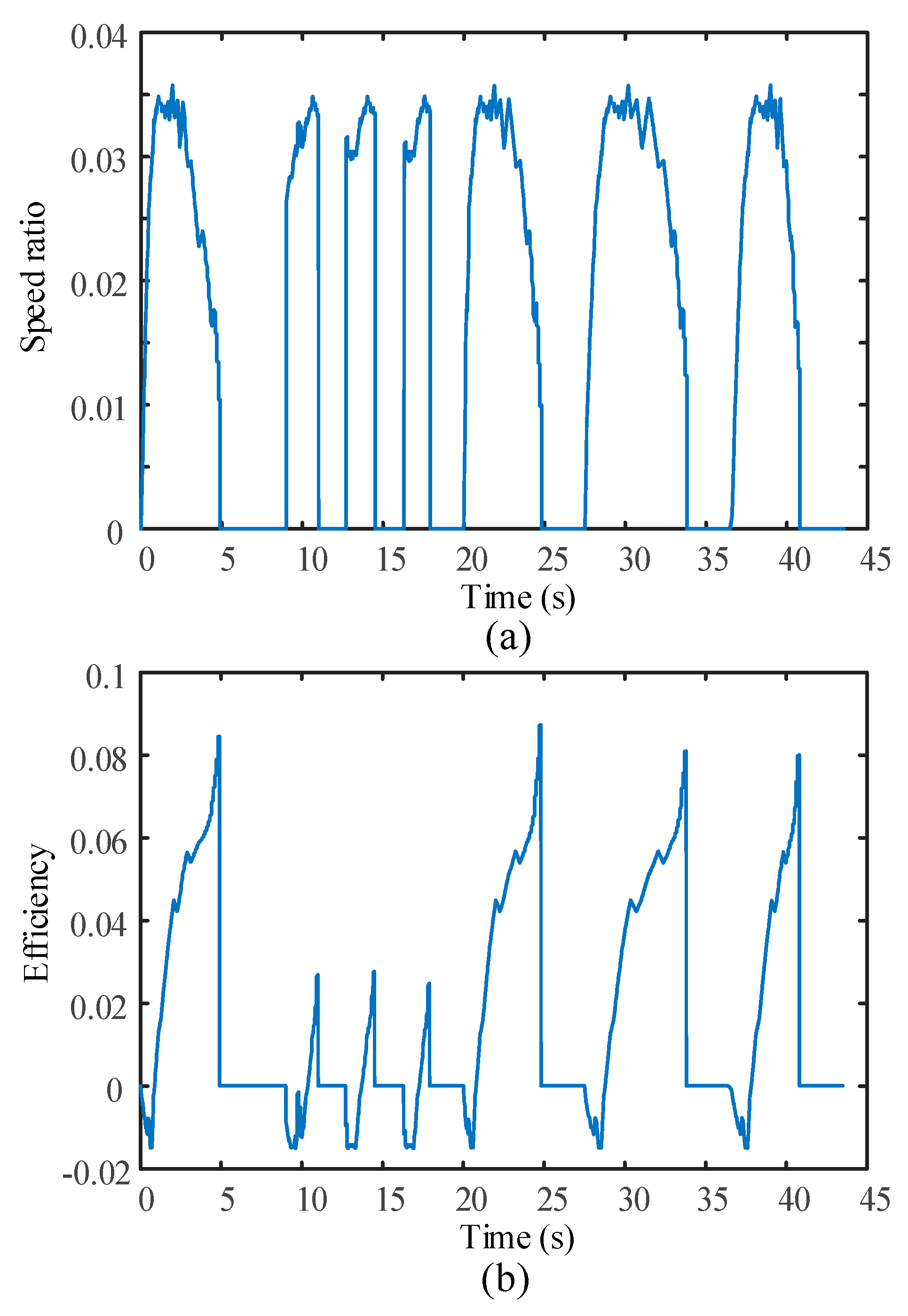
Since the engine efficiency, speed ratio and efficiency of the HMPSTs or TC determine the fuel consumption of a wheel loader, the comparisons on these three factors between the two schemes are conducted. Figure 17a shows the values of speed ratio of solution c minus that of the prototype. All the speed ratios of solution c are greater than those of the prototype when the engine operates at the non-idle state, which facilitates the display of the fine fuel economy of this architecture relative to the prototype. The speed ratio surplus at the heavy load mode can narrow the efficiency gap between the prototype and the solution c, while in the light and medium load mode, the speed ratio surplus of solution c can increase the efficiency benefit relative to the prototype further.
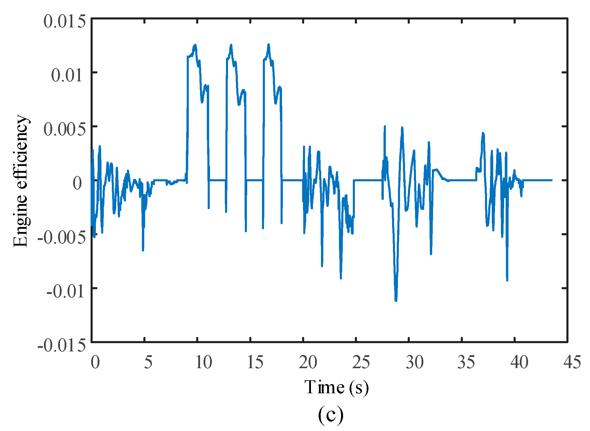
These phenomena are reflected in Figure 17b, where the solution c efficiency is slightly less than the prototype efficiency only at the start stage of wheel loader and a few parts of the heavy load mode. Moreover, in the light and medium load mode, the solution c shows its prominent efficiency advantages over the prototype. Taken together, the solution c can attain an efficiency advantage over the prototype in the global working range, which helps to reduce the fuel consumption. Figure 17c presents the results for the engine efficiency of the wheel loader using solution c minus that of wheel loader using the prototype. All of these differences are less than 0.015, which indicates the solution c cannot fundamentally change the engine working areas of each load mode. The reasons are that the HMPST is a self-adaptive mechanism and cannot control the engine to work in specified areas. In the heavy load mode, the engine efficiency of solution c is slightly higher than that of the prototype. This is because the solution c efficiency is less than the prototype efficiency in this mode, which results in a larger engine output power for the same power requirements, so the working points of the engine have to move to the lower speed and higher efficient areas. On the whole, the solution c can gain an engine efficiency advantage over the prototype in the global working range, which helps to reduce the fuel consumption.
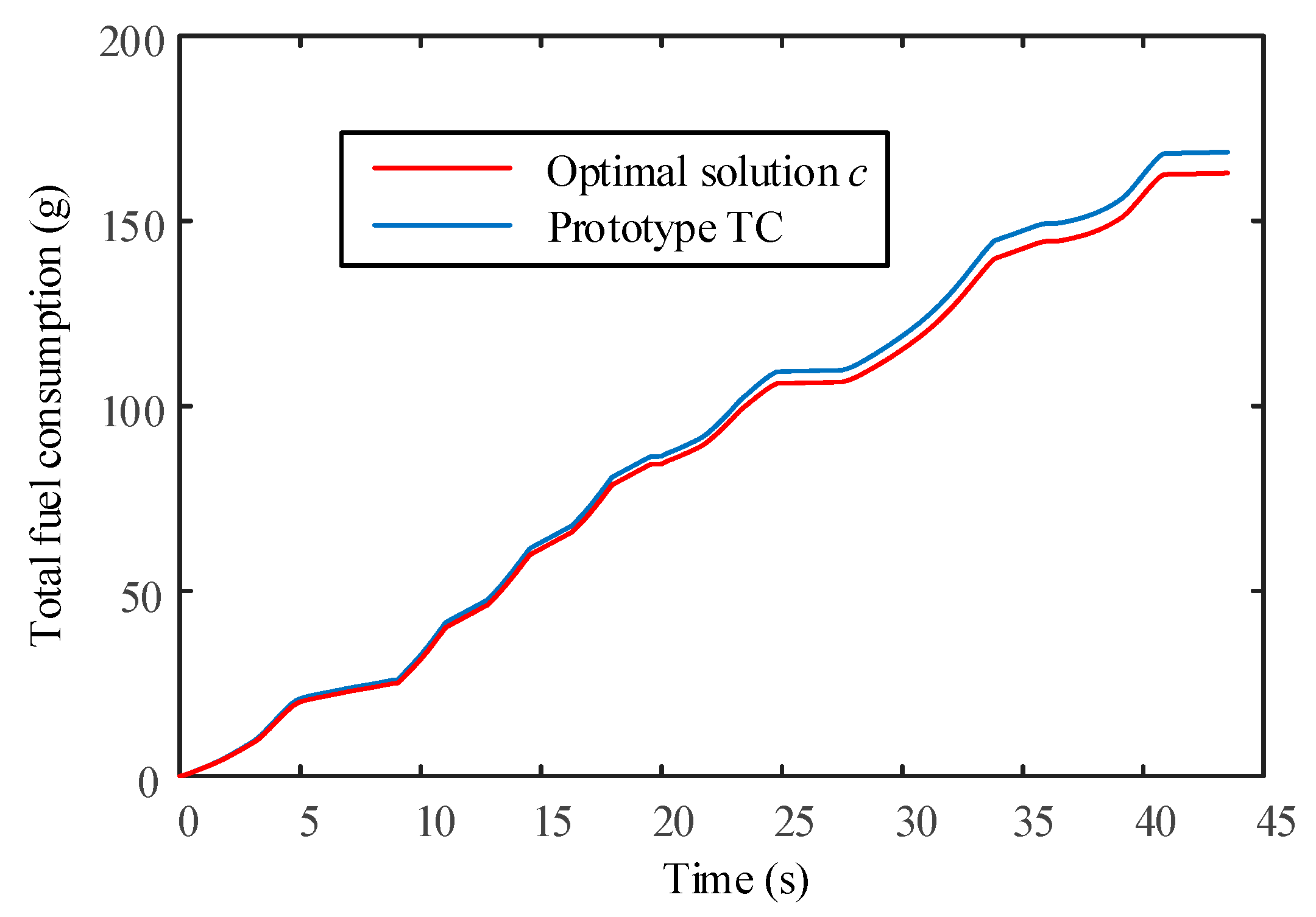
From the above, it is concluded that compared with the prototype TC, HMPST solution c can reduce the fuel consumption effectively in the global range. Figure 18 shows the total fuel consumption for these two architectures. The fuel consumption of solution c is obviously less than that of the prototype after the wheel loader implements heavy loads. Table 2 presents the total fuel consumption for the 50 repetitive typical operating modes. By applying the optimal HMPST solution c, the fuel economy of the wheel loader improved by 3.38%. Similarly, the total fuel consumption for the sub-optimal solution c is listed in Table 2, and its design variables are [3.33 0.315]. The sub optimal solution c presents a fuel savings of 2.9%. Therefore, the TC can be substituted by this type of HMPST in wheel loader applications.
5.3. Discussion
A novel design methodology for HMPSTs is proposed in this paper, in order to find the optimal energy saving solution relative to the prototype TC. The solution c has an advantage of energy saving over the schemes proposed in [7,12]. Although the optimal solution c is only verified in the typical operating mode, it can provide an energy saving advantage over the prototype TC in other operating modes as well. The reasons can be explained from two aspects. First, the design method proposed is based on the three load modes of engine, the two power flows of engine, and the five segments of operating mode of wheel loader. These three aspects are the basic characteristics of a wheel loader. Second, as analyzed in the Section 3.2 and Section 5.2, the solution c can gain both efficiency and engine efficiency over the prototype TC in the global range. Due to the relatively complex design method for HMPSTs and the article length restrictions, a sensitivity analysis of the weighting factors of the operating mode are not considered in this paper. Further investigations on this issue should be carried out.
6. Conclusions
In this paper, a HMPST was used to replace the existing TC for improving the fuel economy of wheel loaders. The initial selection for the HMPSTs was conducted based on the lever diagram. It was found that only four solutions can be applied to a wheel loader. Furthermore, the basic characteristics of these four solution were analyzed, and the results show all four solutions cannot show efficiency advantages over the prototype TC at all speed ratio points, which makes a design optimization of each solution necessary.
The optimized results show that only solution c can display a fuel savings benefit compared with the prototype TC. Despite the large numbers of possible configurations for the HMPSTs, the feasible solution replacing the TC is considerably less than expected. This situation may be due to the form of the prototype TC. If the basic characteristics of the prototype TC could be altered, more feasible solutions could applied to wheel loader. The effectiveness of solution c with the optimal structural parameters is validated in the Matlab/Simulation environment. The simulation results show that the solution c presents a fuel savings rate with 3.38% compared to the prototype TC. It is expected that the optimized HMPST solution c can be an ideal alternative to the existing TCs.
Acknowledgments
The work presented in this paper is funded by the National Natural Science Foundation of China (No. 51375505).
Author Contributions
Xiaojun Liu conceived the initial concept and developed the design methodology, as well as wrote the paper. Dongye Sun produced the mathematical model and SIMULINK program. Datong Qin and Junlong Liu conceived the structure and research direction of the paper.
Conflicts of Interest
The authors declare no conflict of interest.
References
- Fitriani, H.; Lewis, P. Comparison of Predictive Modeling Methodologies for Estimating Fuel Use and Emission Rates for Wheel Loaders. In Proceedings of the Construction Research Congress 2014, Atlanta, GA, USA, 19–21 May 2014. [Google Scholar]
- Bohman, M. On Predicting Fuel Consumption and Productivity of Wheel Loaders. Master’s Thesis, Lulea University of Technology, Lulea, Sweden, 2006. [Google Scholar]
- Nilsson, T.; Fröberg, A.; Åslund, J. Development of look-ahead controller concepts for a wheel loader application. Oil Gas Sci. Technol. 2015, 70, 159–178. [Google Scholar] [CrossRef]
- Schneider, M.; Koch, O.; Weber, J. Green Wheel Loader–Improving Fuel Economy through Energy Efficient Drive and Control Concepts. In Proceedings of the 10th International Fluid Power Conference (10. IFK), Dresden, Germany, 8–10 March 2016; Volume 2, pp. 63–78. [Google Scholar]
- Renius, K.T.; Resch, R. Continuously Variable Tractor Transmissions. In Proceedings of the ASAE Conference on Agricultural Equipment Technology, Louisville, KY, USA, 14–16 February 2005; pp. 1–37. [Google Scholar]
- Macor, A.; Rossetti, A. Optimization of hydro-mechanical power split transmissions. Mech. Mach. Theroy 2011, 46, 1901–1919. [Google Scholar] [CrossRef]
- Wang, H.; Sun, D.; Qin, D. A new continuously variable transmission system applied to transmission system of the roadheader’s cutting unit. Proc. Inst. Mech. Eng. Part C J. Mech. Eng. Sci. 2016. [Google Scholar] [CrossRef]
- Jo, H.; Lim, W.; Park, Y.; Lee, J. Prediction of the performance of a split/circulated power transmission. Proc. Inst. Mech. Eng. Part D J. Automob. Eng. 1999, 213, 235–244. [Google Scholar] [CrossRef]
- Linares, P.; Méndez, V.; Catalán, H. Design parameters for continuously variable power-split transmissions using planetaries with 3 active shaft. J. Terramech. 2010, 47, 323–335. [Google Scholar] [CrossRef] [Green Version]
- Achtenova, G.; Budinsky, T. Analysis and Guidelines for Design of Efficient Power-Split Systems; SAE Technical Paper; SAE International: Detroit, MI, USA, 2012. [Google Scholar]
- Zhao, K.; Bai, X.; Liu, Y.; Chen, W.; Li, G. Simulation study on reasonable matching of powertrain system for crawler bulldozer. China J. Highway Transp. 2013, 26, 183–190. (In Chinese) [Google Scholar]
- Wang, H.; Sun, D. Optimal matching between a diesel engine and a PRHTS transmission. J. Braz. Soc. Mech. Sci. Eng. 2017, 39, 3375–3387. [Google Scholar] [CrossRef]
- Nilsson, T.; Fröberg, A.; Åslund, J. Predictive control of a diesel electric wheel loader powertrain. Control Eng. Pract. 2015, 41, 47–56. [Google Scholar] [CrossRef]
- Sakaguchi, S.; Kimura, E.; Yamamoto, E. Development of an Engine-CVT Integrated Control System; SAE Technical Paper; SAE International: Detroit, MI, USA, 1999. [Google Scholar]
- Oh, K.; Kim, H.; Ko, K.; Kim, P.; Yi, K. Integrated wheel loader simulation model for improving performance and energy flow. Automat. Constr. 2015, 58, 129–143. [Google Scholar] [CrossRef]
- Nezhadali, V.; Frank, B.; Eriksson, L. Wheel loader operation—Optimal control compared to real drive experience. Control Eng. Pract. 2016, 48, 1–9. [Google Scholar] [CrossRef]
- Zou, N.; Huang, H.; Zhang, E.; Dai, Q. Establish oriented operating terminals wheel loader duty cycle. Trans. Chin. Soc. Agric. Eng. 2015, 31, 78–85. (In Chinese) [Google Scholar]
- Filla, R.; Ericsson, A.; Palmberg, J.O. Dynamic Simulation of Construction Machinery: Towards an Operator Model. In Proceedings of the International Fluid Power Exhibition 2005 Technical Conference, Las Vegas, NV, USA, 16–18 March 2005. [Google Scholar]
- Pettersson, K.; Krus, P. Design optimization of complex hydromechanical transmissions. J. Mech. Des. 2013, 135, 1–9. [Google Scholar] [CrossRef]
- Lei, Z.; Qin, D.; Liu, Y.; Peng, Z.; Lu, L. Dynamic energy management for a novel hybrid electric system based on driving pattern recognition. Appl. Math. Model. 2017, 45, 940–954. [Google Scholar] [CrossRef]
- Hrovat, D.; Tobler, W.E. Bond graph modeling and computer simulation of automotive torque converters. J. Frankl. Inst. 1985, 319, 93–114. [Google Scholar] [CrossRef]
- Jandasek, V.J. The Design of Single-Stage Three-Element Torque Converter; SAE Technical Paper; SAE International: Detroit, MI, USA, 1961. [Google Scholar]
- Wang, W.; Song, R.; Guo, M.; Liu, S. Analysis on compound-split configuration of power-split hybrid electric vehicle. Mech. Mach. Theroy 2014, 78, 272–288. [Google Scholar] [CrossRef]
- Son, H.; Park, K.; Hwang, S.; Kim, H. Design methodology of a power split type plug-in hybrid electric vehicle considering drivetrain losses. Energies 2017, 10, 437. [Google Scholar] [CrossRef]
- Macor, A.; Rossetti, A. Fuel consumption reduction in urban buses by using power split transmissions. Energ. Convers. Manag. 2013, 71, 159–171. [Google Scholar] [CrossRef]
- Mantriota, G. Performance of a parallel infinitely variable transmissions with a type II power flow. Mech. Mach. Theory 2002, 37, 555–578. [Google Scholar] [CrossRef]
Figure 1.
Wheel loader powertrain architecture.
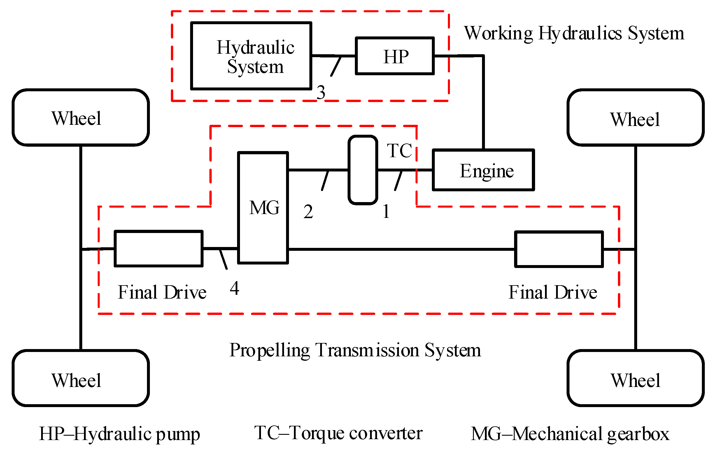
Figure 2.
V-cycle of wheel loader.
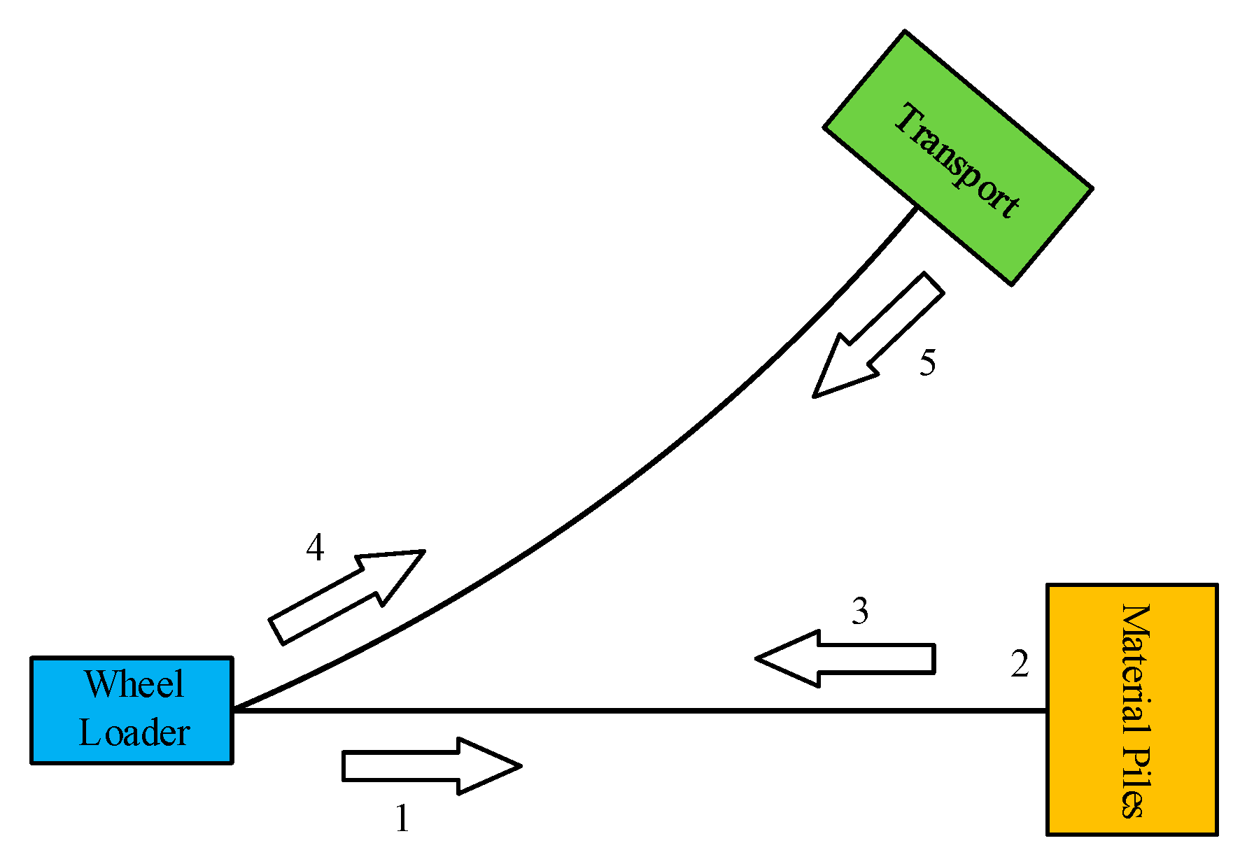
Figure 3.
Objective wheel loader.

Figure 4.
Operating mode of wheel loader. (a) Vehicle speed; (b) Thrusting resistance; (c) Whole vehicle mass; (d) Load torque of hydraulic pump; (e) Division of engine power between propelling transmission system and working hydraulics system.
Figure 4.
Operating mode of wheel loader. (a) Vehicle speed; (b) Thrusting resistance; (c) Whole vehicle mass; (d) Load torque of hydraulic pump; (e) Division of engine power between propelling transmission system and working hydraulics system.

Figure 5.
Loading characteristics of torque converter (TC).
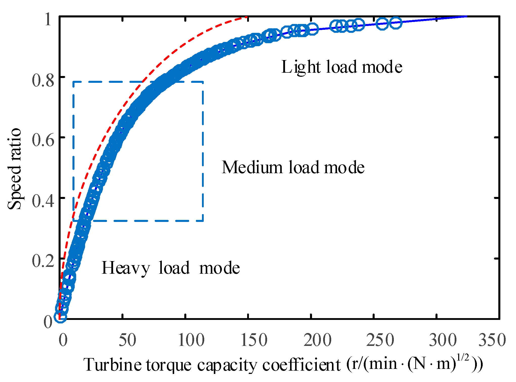
Figure 6.
Two types of HMPSTs. (a) Input torque coupled architecture; (b) Output torque coupled architecture.
Figure 6.
Two types of HMPSTs. (a) Input torque coupled architecture; (b) Output torque coupled architecture.
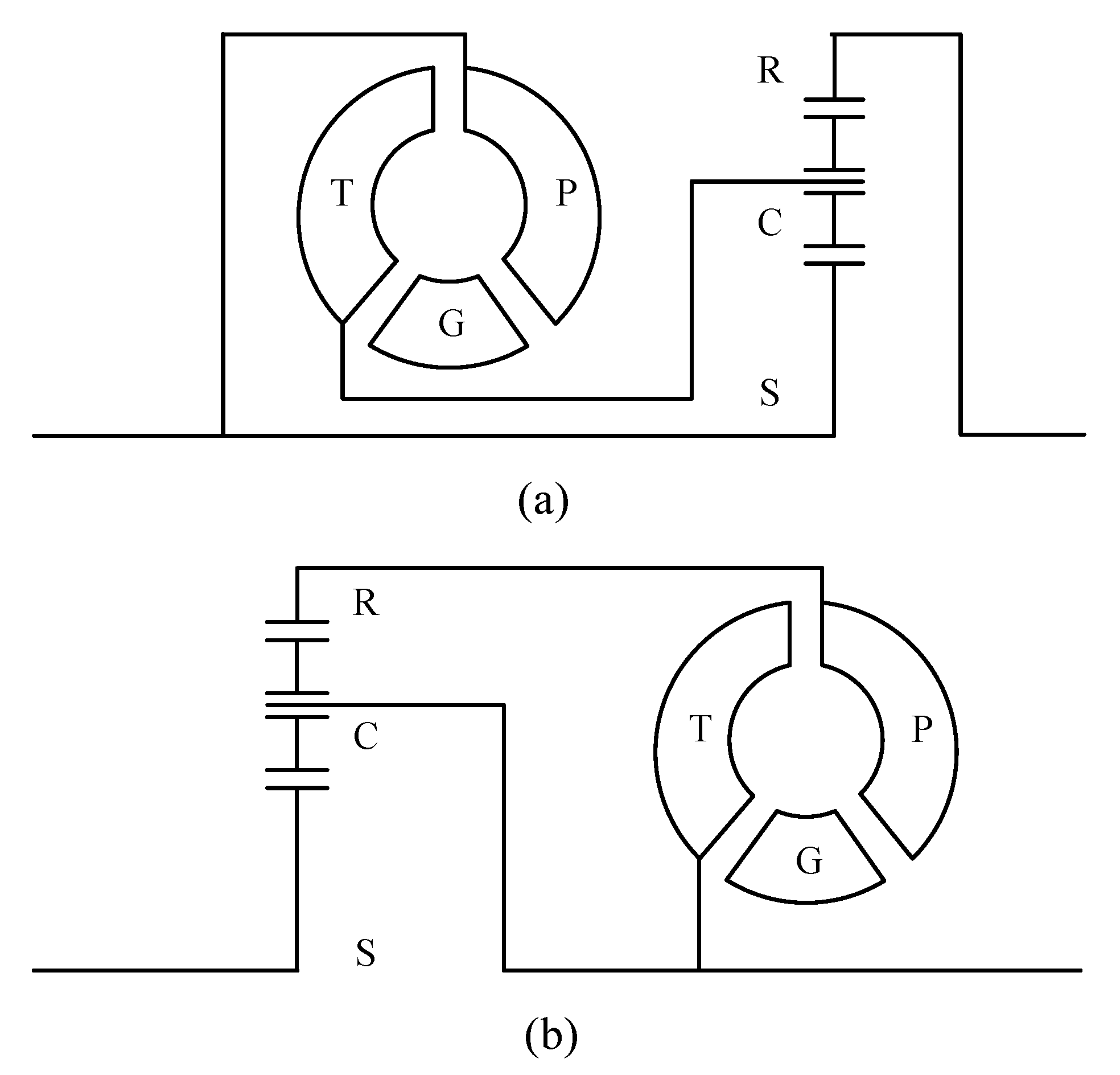
Figure 7.
Lever diagram. (a) Discriminant method for the scheme in Figure 6a; (b) Discriminant method for the scheme in Figure 6b.

Figure 8.
Four reasonable solutions for HMPSTs. (a) Solution a; (b) Solution b; (c) Solution c; (d) Solution d.
Figure 8.
Four reasonable solutions for HMPSTs. (a) Solution a; (b) Solution b; (c) Solution c; (d) Solution d.

Figure 9.
Efficiency of each solution. (a) ; (b) .

Figure 10.
Loading characteristics of each solution. (a) , D = 0.3 m; (b) , D = 0.3 m.
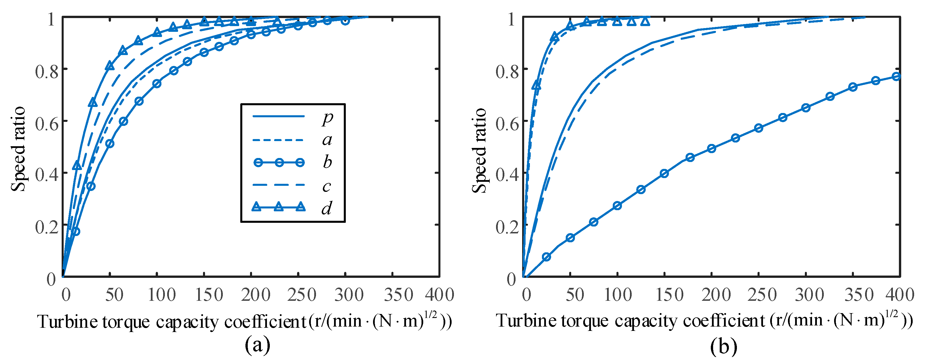
Figure 11.
Engine efficiency.

Figure 12.
Solving flow chart.
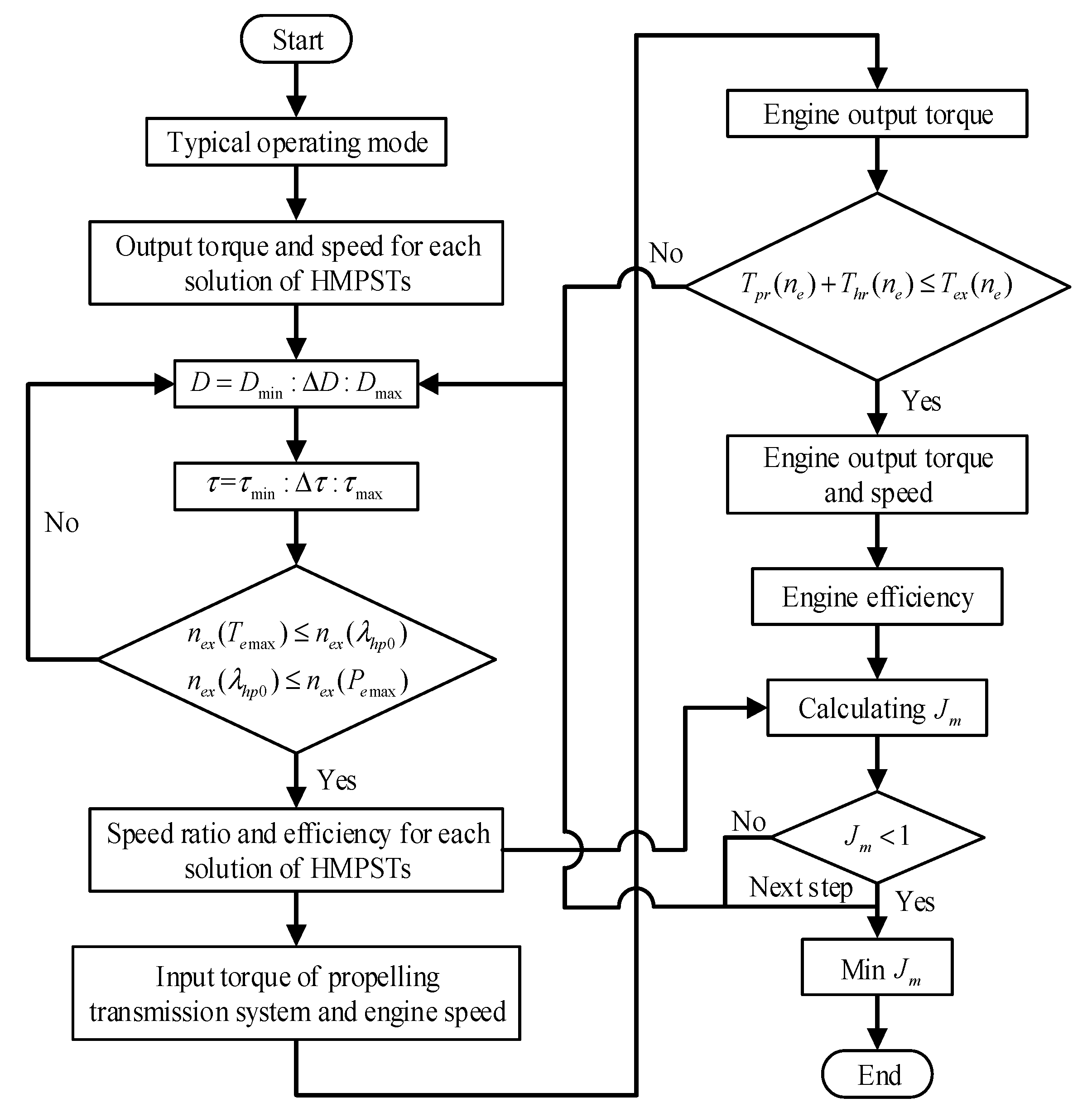
Figure 13.
Solutions for scheme c.

Figure 14.
Architecture of solution c.

Figure 15.
Basic characteristics of solution c. (a) Efficiency; (b) Loading characteristics.

Figure 16.
Load power of engine and working hydraulics system. (a) Prototype TC; (b) Solution c.

Figure 17.
Difference between the solution c and the prototype TC. (a) Speed ratio; (b) Efficiency; (c) Engine efficiency.
Figure 17.
Difference between the solution c and the prototype TC. (a) Speed ratio; (b) Efficiency; (c) Engine efficiency.


Figure 18.
Total fuel consumption.


Table 1.
Basic parameters of the wheel loader.
| Parameters | Value |
|---|---|
| Vehicle mass (kg) | 16,800 |
| Working loads (kg) | 5000 |
| Rolling radius (m) | 0.75 |
| Rolling resistance coefficient | 0.033 |
| Engine rated power (kW) | 163 |
| Engine maximum torque (N·m) | 872 |
| TC effective diameter (m) | 0.34 |
| TC torque ratio at stall state | 2.52 |
| Mechanical gearbox speed ratio | 4.278/2.368/1.126/0.648 |
| Mechanical gearbox efficiency | 0.92 |
| Final drive speed ratio | 4.625 |
| Final drive efficiency | 0.95 |
| Wheel reducer speed ratio | 4.875 |
| Wheel reducer efficiency | 0.95 |
Table 2.
Comparison results for total fuel consumption.
| Objective | Fuel Consumption (L) | Savings (%) |
|---|---|---|
| Prototype TC | 10.35 | - |
| Optimal solution c | 10.00 | 3.38 |
| Sub optimal solution c | 10.05 | 2.90 |
© 2017 by the authors. Licensee MDPI, Basel, Switzerland. This article is an open access article distributed under the terms and conditions of the Creative Commons Attribution (CC BY) license (http://creativecommons.org/licenses/by/4.0/).
Share and Cite
MDPI and ACS Style
Liu, X.; Sun, D.; Qin, D.; Liu, J. Achievement of Fuel Savings in Wheel Loader by Applying Hydrodynamic Mechanical Power Split Transmissions. Energies 2017, 10, 1267. https://doi.org/10.3390/en10091267
AMA Style
Liu X, Sun D, Qin D, Liu J. Achievement of Fuel Savings in Wheel Loader by Applying Hydrodynamic Mechanical Power Split Transmissions. Energies. 2017; 10(9):1267. https://doi.org/10.3390/en10091267
Chicago/Turabian StyleLiu, Xiaojun, Dongye Sun, Datong Qin, and Junlong Liu. 2017. "Achievement of Fuel Savings in Wheel Loader by Applying Hydrodynamic Mechanical Power Split Transmissions" Energies 10, no. 9: 1267. https://doi.org/10.3390/en10091267
Note that from the first issue of 2016, this journal uses article numbers instead of page numbers. See further details here.