3-D FEM Analysis, Prototyping and Tests of an Axial Flux Permanent-Magnet Wind Generator


1
Department of Electrical and Computer Engineering, University of Patras, 26500 Patras, Greece
2
Electrical and Computer Engineer, Amazonon 3 Evrytania, 36100 Karpenissi, Greece
3
Electrical and Computer Engineering student, University of Patras, 26500 Patras, Greece
*
Author to whom correspondence should be addressed.
Energies 2017, 10(9), 1269; https://doi.org/10.3390/en10091269
Submission received: 20 June 2017
/
Revised: 22 August 2017
/
Accepted: 23 August 2017
/
Published: 26 August 2017
(This article belongs to the Section F: Electrical Engineering)
Abstract
:This paper contributes to the research and development of Axial Flux Permanent Magnet Synchronous Machines (AFPMSM); and in particular the design, the construction stages and measurements of a double rotor single internal non-ferromagnetic stator with a trapezoidal-concentrated winding machine for wind power generation applications. The initial dimensions of the machine were calculated using analytical formulas and a model was created and analyzed using the 3D Finite Element Method (FEM). The shape of the magnets of the machine was optimized and presented in a previous paper and a prototype was constructed and tested in the laboratory. In addition, a temperature test of the stator was performed experimentally. Finally, the effect of the different axial widths of the two air gaps on the electrical magnitudes and the field of the machine were investigated using both FEM analysis and experiments.
1. Introduction
Research on the design and construction of Axial Flux Permanent Magnet Synchronous Machines (AFPMSM) has been attracting increasing scientific interest over the past few years. These types of machines have been used in various industrial applications such as wind power generation, ship propulsion drives and electric vehicles as well as in numerous other related studies which can be found in the literature [1,2,3,4,5,6]. Despite the recent increase in published research on this topic, the investigation design and manufacturing processes for AFPM machines is still ongoing.
Compared to the Radial Flux Synchronous Machines, the AFPMSMs offer advantages in certain applications. They have a compact and robust structure, the length of the air-gap is small, their volume is limited and their efficiency and power-to-weight ratio are high. They consist of several modules, which can be adjusted to power or torque requirements [7,8,9,10,11]. The number of permanent magnets can be large, making these machines suitable for high frequency or low speed applications such as electric vehicle traction or ship propulsion drives and wind power generation. They can also be directly coupled to low-speed turbines, wind, or hydro turbines, thus the use of gear-boxes, which is maintenance demanding is avoided and the system becomes lighter, less noisy, and more efficient [12].
Several AFPMSM topologies can be found in the literature concerning the number of modules: single sided machines, the one stator-one rotor and multiple air-gap machines, usually, double sided machines, one stator-two rotors or one rotor-two stators. They can be categorized also, according to the material of the stator and the winding topology. So, the stator can be constructed using ferromagnetic material, slotted or slot-less, or using non-magnetic materials.
In the cases of the non-magnetic material stator core or the coreless stator, the hysteresis and eddy current stator losses, the cogging torque is eliminated and the rotor core losses and acoustic noise are reduced [13,14]. Furthermore, the weight of the machine is reduced and the axial magnetic attractive forces between stator and rotor, at no load are non-existent. The aforementioned forces can cause problems at the construction and when the air gap length is not equal between each rotor and the stator in the multiple air-gap machine topologies. On the other hand, with the use of a coreless stator, the winding inductances become smaller and stronger or larger permanent magnets are needed to produce the same magnetic field.
For the study of different AFPMSM topologies and designs both analytical methods, verified through the Finite Element Method (FEM), or experiments were employed [15,16,17,18,19].
Other papers [20,21] examine this type of AFPMSG topology using analytical magnetic field computation techniques validated by comparison to Finite Element Analysis (FEA) results. The present work, while adopting the same topology of two rotors with one internal coreless stator, is distinctive in terms of having selected the shape of the magnets in relation to the winding shape (non-overlapping trapezoidal) and the machine electromagnetic and performance characteristics based on extensive research (a previously published paper [22]). The behavior of the machine was studied via a 3D FEA model and a prototype was constructed. The basic magnitudes of the machine were measured and compared to the simulation results. Furthermore, a stator temperature test was performed and the effect of the different axial width of the two air-gaps on the electrical and magnetic magnitudes of the machine was investigated. The synchronous generator is intended for wind power generation. The detailed characteristics of the machine are described in the section that follows.
2. AFPM Machine Characteristics
The machine was chosen to have one coreless stator and two rotors. The stator consists of a trapezoidal-concentrated, non-overlapping winding that is buried in a composite material of high temperature epoxy resin. The permanent magnets consist of high energy material, neodymium–iron–boron (NeFeB N42); they are axially magnetized and placed so that a north pole is located after a south pole. The choice of coreless stator has the advantages of simple stator assembly and elimination of the cogging torque. Furthermore, rotor surface losses, magnetic saturation and acoustic noise are reduced compared to the iron stator core.
The machine is designed to be directly coupled to the wind generation system and thus it must be designed with numerous poles to fit the frequency requirements. In cases of wind generation applications, such as the one under study, it is essential to use a Pulse Width Modulation (PWM) converter to maintain steady output voltages and frequency. However, this paper does not focus on the converter that will be the subject of future research. The initial dimensions of the machine were calculated by using known formulas [7,23,24]. The magnet dimensions, the number of poles, the coil shape, size and its number of turns, the air gap length and the overall diameter of the generator were the basic chosen parameters that were used in the theoretical equations to extract the remaining machine parameters. Several 3D Finite Element Models were designed and analyzed with the use of a commercial software package, opera 3D in order to study and optimize the performance of the generator. The machine is intended for small direct-drive wind-energy conversion systems. A realistic speed value for safe operation of the machine is 375 rpm, which corresponds almost to 5 bf wind for the chosen wind turbine. Firstly, the basic magnitudes of the 3-phase generator with two rotors and one inner stator were chosen according to our requirements and the good and safe operation of the machine [7], as presented in Table 1.
The rest of the basic magnitudes were calculated using proper sizing equations and assumptions [7] and they are listed in Table 2. Equation (1) was used to compute the axial thickness of the stator, Equation (2) to compute the peak value of the phase voltage, and Equation (3) for the developing torque of the machine.
where, g is the air-gap axial thickness, hm is the magnet axial thickness, μrrec is the relative magnetic permeability of the magnets, Br is the remaining magnetization of the magnets, Bmg is the maximum density of magnetic flux that is just above the surface of the magnet.
where, q is the number of coils per phase, p is the number of poles, α is the number of parallel circuits, l is the active length of the winding (ro − ri), N is the number of coil turns, Bρ is the maximum value of the magnetic flux density (1st harmonic) in the gap, re is the average radius of the stator winding ((ro + ri)/2), kd is the distribution factor of the winding, kp is the pitch factor of the winding, ω is the electrical speed.
Each rotor disc consists of 16 magnets of alternating polarity. The permanent magnets were glued in the surface of the rotors. Their shape resulted from FEM analysis, published in a former paper [22], by comparing the machine electromagnetic and performance characteristics obtained for different magnet shapes [9,23,24,25]. The stator winding is concentrated and non-overlapping and plunged in a supporting structure made of high temperature epoxy resin (non-magnetic and non-conductive material). Multi-turns of trapezoidal coils of isolated conductors form the winding.
The prototype machine that resulted from the optimized FEM analysis model was constructed in the university laboratory, apart from the metal parts which were made in the university machine shop. A test bench was also developed in the laboratory to measure the prototype performance. Accurate measurements were taken in order to compare and evaluate the constructed machine with the simulation 3D FEM model. In addition, the constructed prototype stator was submitted to temperature tests. Finally, an investigation of the effect of unequal width air-gaps on the electrical characteristics and the field of the machine was conducted.
3. Design Optimization and Simulation Results
The impact of magnet design in machine performance has been extensively investigated and presented in a previous paper [22]. The categorization of the magnets depends on their shape, hence their label categorization as radial, conventional skew, dual skew and finally triangular skew magnets. Figure 1 presents the corresponding designs used in the simulations. In each model, the number and the radial length of the magnets is the same, but the volume of the magnetic material is different, due to the different designs. In order for the simulation results to be comparable, all model dimensions and test conditions apart from the magnets shape were kept unaltered. The magnets used in the simulation are NdFeB, grade Ν42 and the magnetization curve (B-H) that was used was identical to the magnetization curve provided by the manufacturer.
The under-investigation simulation models were compared for the same load and revolution speed. The selected model was the one with triangular skew magnets, Figure 1d, because of its high output power, power factor, low cost and simplicity of production [25]. Regarding the FEA models, the appropriate mesh size must be used at the different parts of the machine concerning the precision of the computation results. The densest mesh design is needed for the air-gap area, where the number of the surface elements is ~75,000 and the volume elements ~375,000. The required time for one time-step iteration is ~7 min with Intel Core i5-3570K CPU @ 3.5 GHz, 16 GB RAM and 64-bit operating system (Microsoft Windows, Washington, DC, USA).
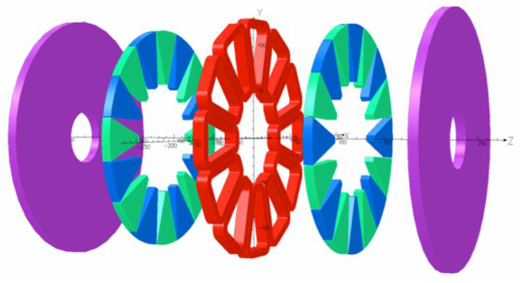
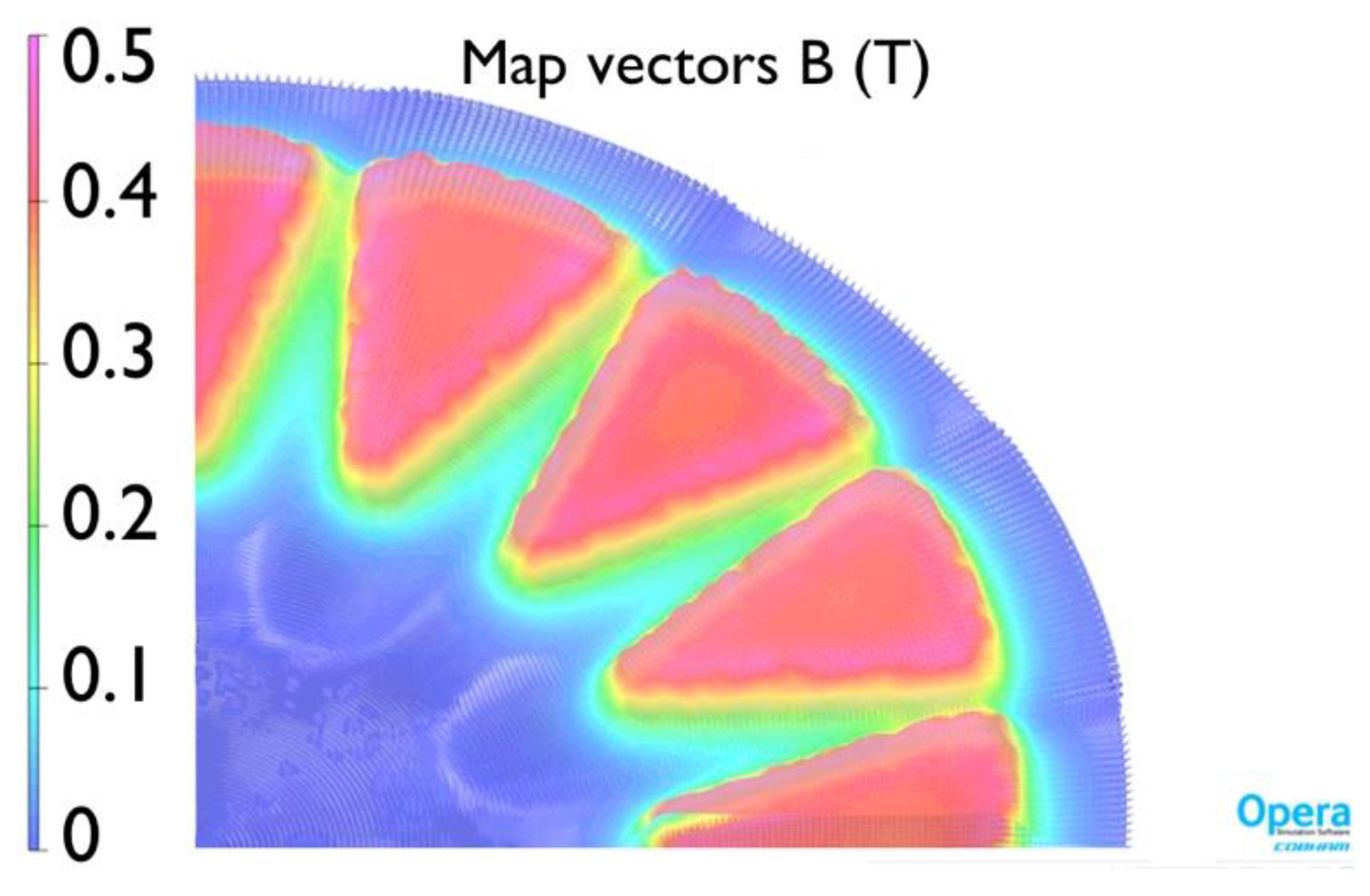
The final model was simulated both at no load (∞[Ohm]) and under load conditions. Figure 2 presents the 3D simulated model in exploded preview. Figure 3 presents the magnetic flux density distribution in absolute values in a slice in the middle of the air gap where, as expected, the maximum values appear in the edges of the magnet. Similar distribution of the magnetic flux density appears throughout the axial length of the machine. The simulation results for the Root Mean Square (RMS) phase voltage at no-load (Back- Electromotive Force (EMF)) and output power under 70 Ω load versus the speed are presented in Figure 4 and Figure 5 respectively. The simulation was non-linear taking into account the magnetization characteristics of the selected materials provided by our suppliers. The waveform of the Back-EMF versus the speed is presented in Figure 4 and it is consistent with the linear relationship between them. The waveform of the output power versus the speed in Figure 5 presents the expected form.
4. Prototype Experimental Measurements
4.1. Construction Process
In order to construct the machine with high precision compared to the simulation model, a specified process was followed; nevertheless, some necessary modifications of the constructed machine compared to the original design were made, as described here. The handmade winding is fabricated using copper of 0.8 mm diameter. The total length of the winding is 186.23 m per phase. Since the height of the winding was slightly larger that the predicted one, the outer radius of the constructed stator and rotor was increased. As widely documented, the ratio of internal to external radius, σ, of the machine affects significantly the performance characteristics, so it must be chosen appropiatelly [7,24]. Therefore, the height of the internal radius was equally increased, to keep the same ratio σ. The magnets, with the same shape and dimentions as per the FEM, were placed in the same relative position according to the winding, but the distance between two adjacent magnets was slightly increased too. The FEA model was modified accordignly to reflect the aforementioned modifications of the construcetd machine, in order to compare the simulation and experimental results in a robust manner. The constructed AFPM machine was tested under varius speeds under no-load (∞[Ohm]) and load conditions. Furtheremore, a stator temperature test was performed and finally, the machine performance with two unequal air gaps was investigated.
4.2. Test Bench Construction and Measurement Instruments
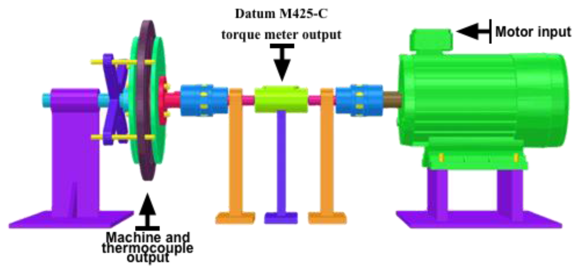
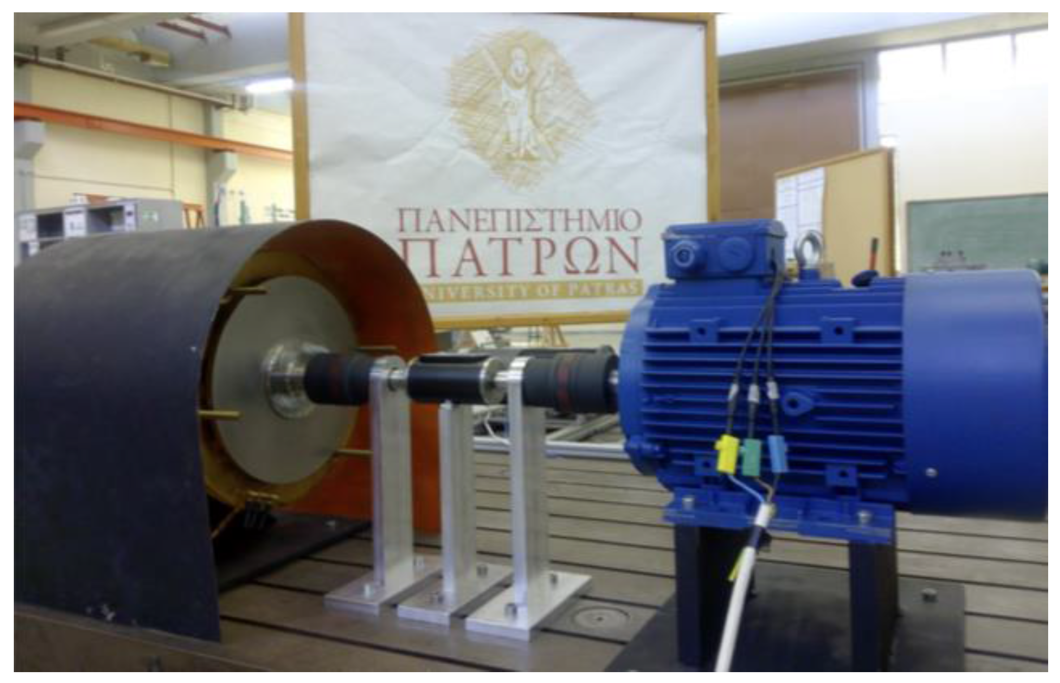
A test bench was constructed in the laboratory to perform measurements on the prototype machine. The AFPMSG was connected to a two pole 7.5 kW, 400 V, induction motor. The induction motor was driven by a voltage source inverter and during the load tests a variable 3-phase resistance was connected to the terminals of the generator. A NI-6211 usb card (LabVIEW-National Instruments, Austin, TX, USA) collected the current and torque measurements. The Datum M425-C torque meter (Datum electronics, East Cowes, UK) with a DYI interface measured the torque with 1000 samples/sec. An in-house current sensor was developed, utilizing LEM LAH25NP Hall Effect current transducers (LEM, Geneva, Switzerland) for the line current measurement. All the current measured signals were sampled with 30 kHz frequency. Also, the Zimmer LM6-500 power analyzer (extremely high measuring accuracy of 0.015% of reading + 0.01% of range at 45–65 Hz) (ZES ZIMMER Electronic Systems, Oberursel (Frankfurt), Germany) was used in order to measure precisely the power output of the axial flux generator. The 3D design of the test bench is illustrated in Figure 6 and the constructed test bench in Figure 7.
4.3. Experimental Results
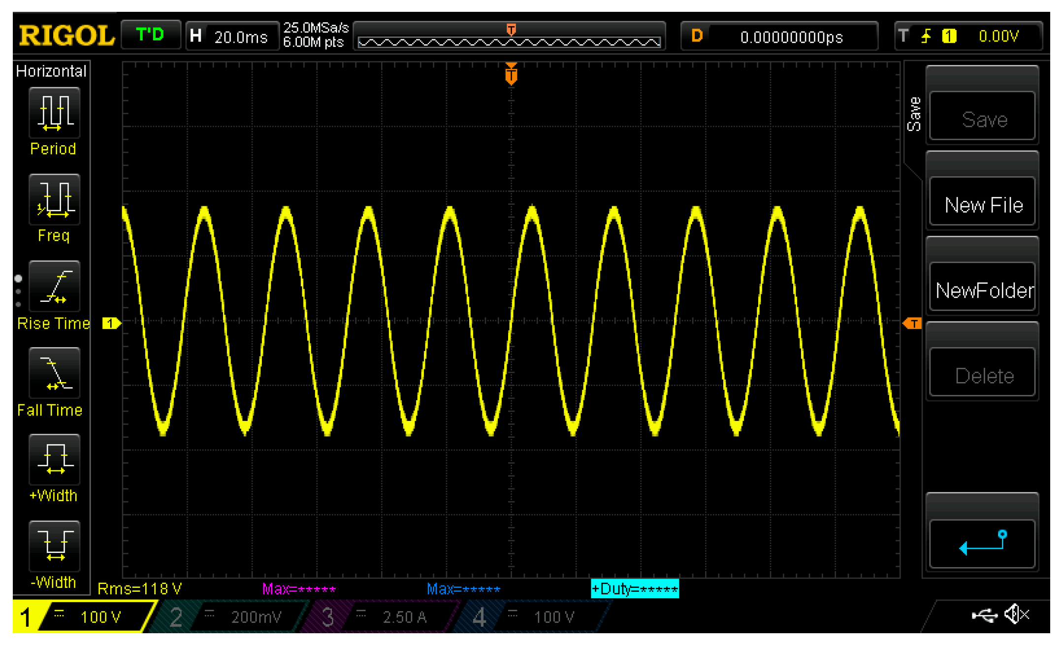
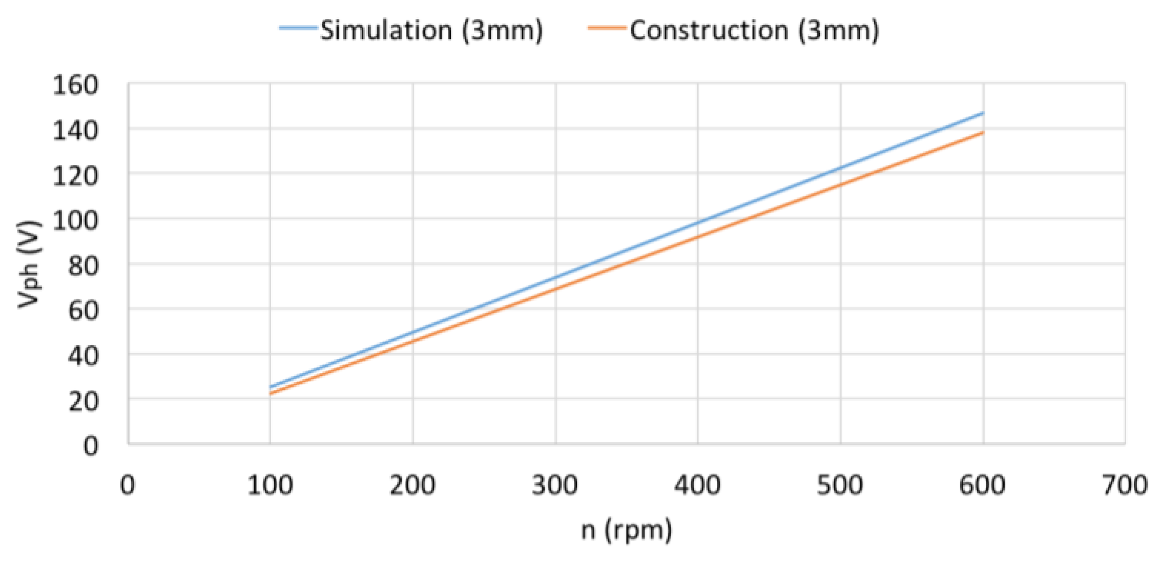
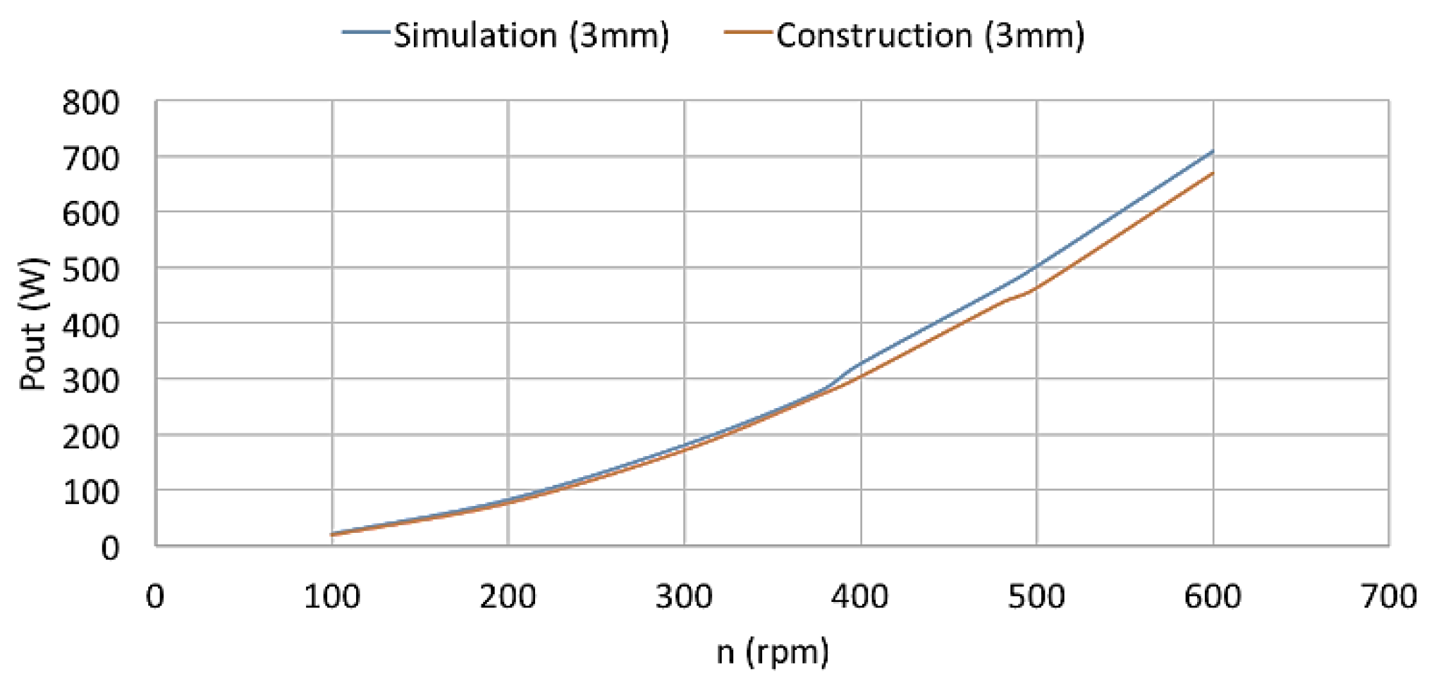
The constructed machine was tested at no-load condition as well as under different loads for the same speed range as in simulations. Figure 8 shows the line voltage waveform of the AFPMSG at no-load condition (Back-EMF) for a speed of 300 rpm (as it is shown in oscilloscope, it has a sinusoidal form and the RMS value of the voltage is 118.6 V). Figure 9 presents the variation of the phase voltage at no-load (Back-EMF) for different speed values, and Figure 10 shows the output power versus the speed for a given load of 70 Ω. Finally, Figure 11 presents simulation and experimental results for a speed of 375 rpm of the output power versus the load per phase. A comparison to the simulated results is presented in the comparable figures. As is shown, the difference between the simulation and experimental results is insignificant, with experimental results showing slightly lower values than simulation.
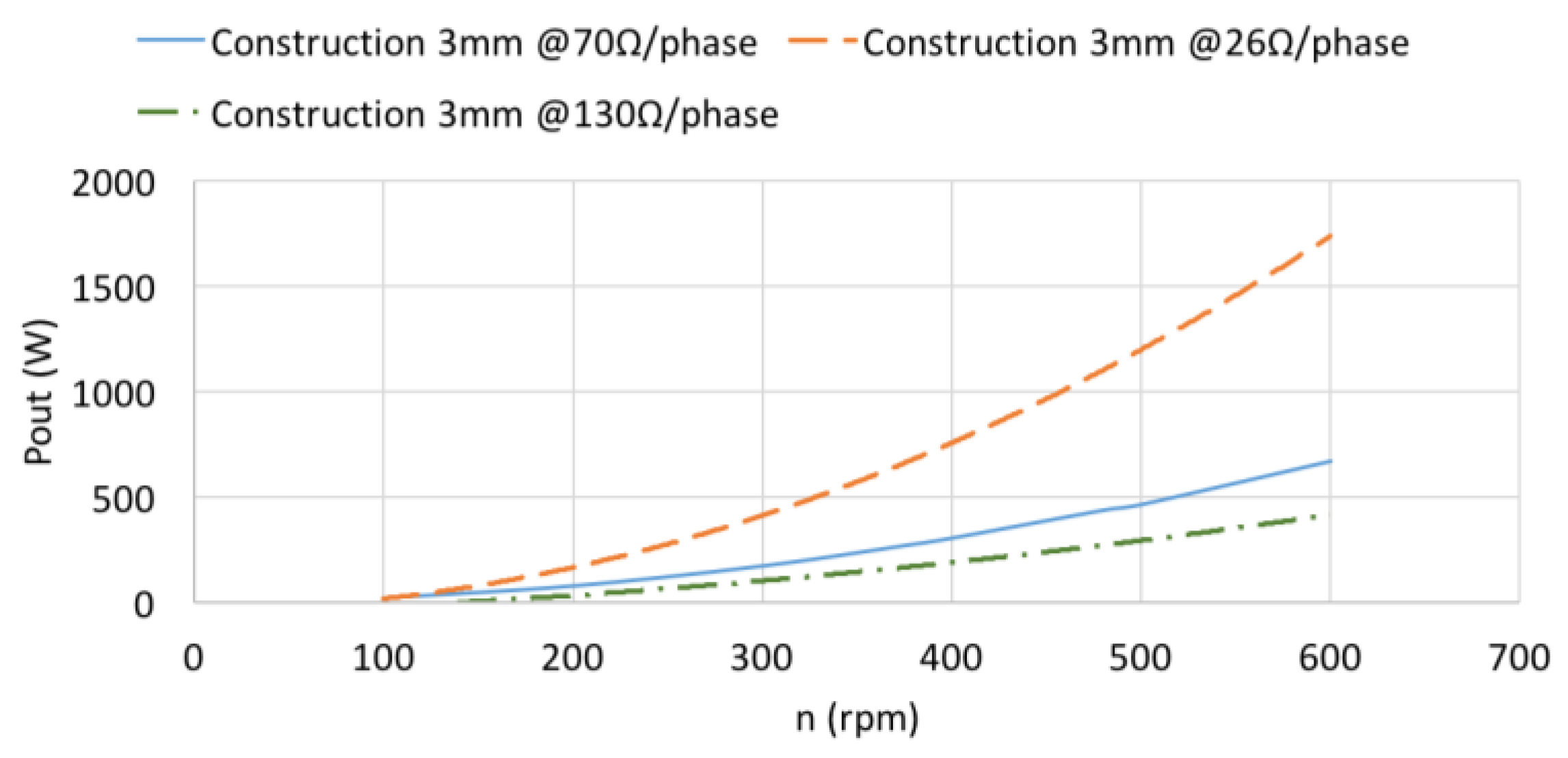
FEM and experimental results are close to each other, especially in the low speed region. At the nominal speed of 375 r/min and a load equal to 70 Ω/phase, an electrical power output of 274.89 W was measured, while the mechanical power input equals 318.47 W. The power losses were esimated by subtraction of the mechanical input and were measured via the torque sensor mounted on the axis and the electrical power output. Eddy current losses in the permanent magnets, mechanical losses in the bearings, and windage losses are present alongside the stator copper losses and the rotor iron losses. At this load condition of 70 Ω/phase, a power loss of 43.58 W is calculated. The RMS phase current was mesured at 1.1 A; taking into consideration the resistance of the winding per phase, the copper losses are calculated at 22.506 W. Figure 12 shows the output power versus the speed under 70, 26 and 130 Ω/phase load with 3 mm air gaps.
4.4. Temperature Test
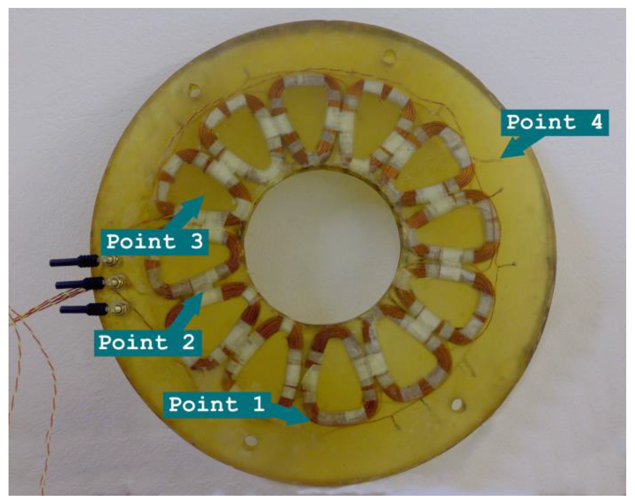
A temperature test was performed before the construction of the rotors in order to check the safe operation of the machine. The crucial magnitude is the temperature of the stator, which consists of windings plunged in the supporting structure made of high temperature epoxy resin with a highest permitted temperature of 120 °C. Several thermocouple sensors were plunged in the supporting structure, the epoxy resin. Their exact position is presented in Figure 13. Point 1 is located on the surface of the winding, while point 4 is located 28 mm away from the end of the winding. Point 3 is placed in the center of a coil area.
With only the stator mounted on the shaft and fed by a 2 A dc current, Figure 14 presents the variation of the temperature over time in different sectors of the stator. As observed, the critical parts are those between the coils, point 2 in Figure 13.
We note that in the same test during normal operation, with the whole machine assembled, the highest temperature in the stator did not exceed 22 °C because of the air-flow due to the rotation of the rotors. These results show the safe operation of the machine under nominal conditions without stator deformation problems.
5. Variation of the Axial Width of the Two Air-Gaps
Due to the manufacturing process, these machines may present imperfections or asymmetries compared to the original theoretical design (manufacturing imperfections). We have considered the case of unequal air-gaps, e.g., due to anomalies on one surface of the epoxy resin in the stator.
This section discusses the effect of the different axial width of the two air gaps on the electrical magnitudes and the field of the machine. We have considered two different cases. In the first case, the axial width of the two air gaps is the same, 3 mm, while in the second case, the widths of the two air gaps are unequal, 2 mm and 4 mm, respectively. We note that in both cases, the total width of the two air-gaps is the same, 6 mm. Several 3D FEM analyses and laboratory tests were performed for each case and the results are presented and compared below.
5.1. Simulation Results
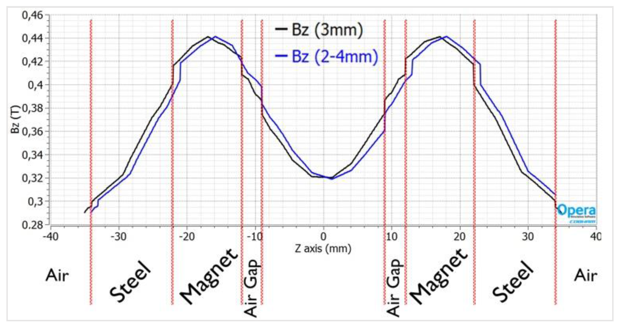
Figure 15 presents the distribution of the normal component of the magnetic flux density for both scenarios, equal and unequal air-gaps. Owing to the large air gap, the maximum flux density does not exceed 0.44 T in both sides; therefore, the magnetic circuit is unsaturated. Also, it can be noticed that the unequal air-gaps do not result in the increase of the field in the side of the smaller air-gap, but only in a slight shift of the waveform.
5.2. Experimental Results
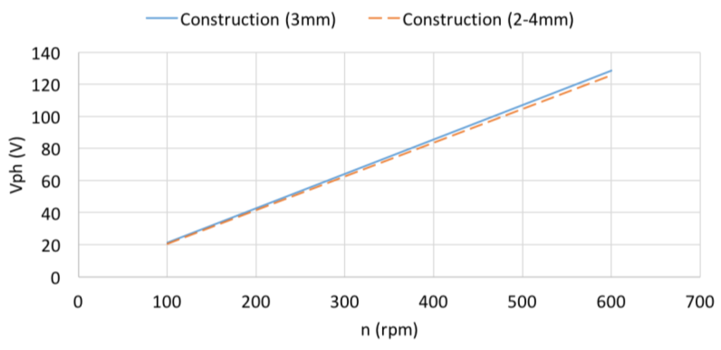
The comparison between the constructed model with 3 mm and 2–4 mm air gaps reveals that the output phase voltage at no-load (Back-EMF) remains unaffected, as it is produced by the magnets field which remains constant. This outcome can be easily deduced from Figure 18.
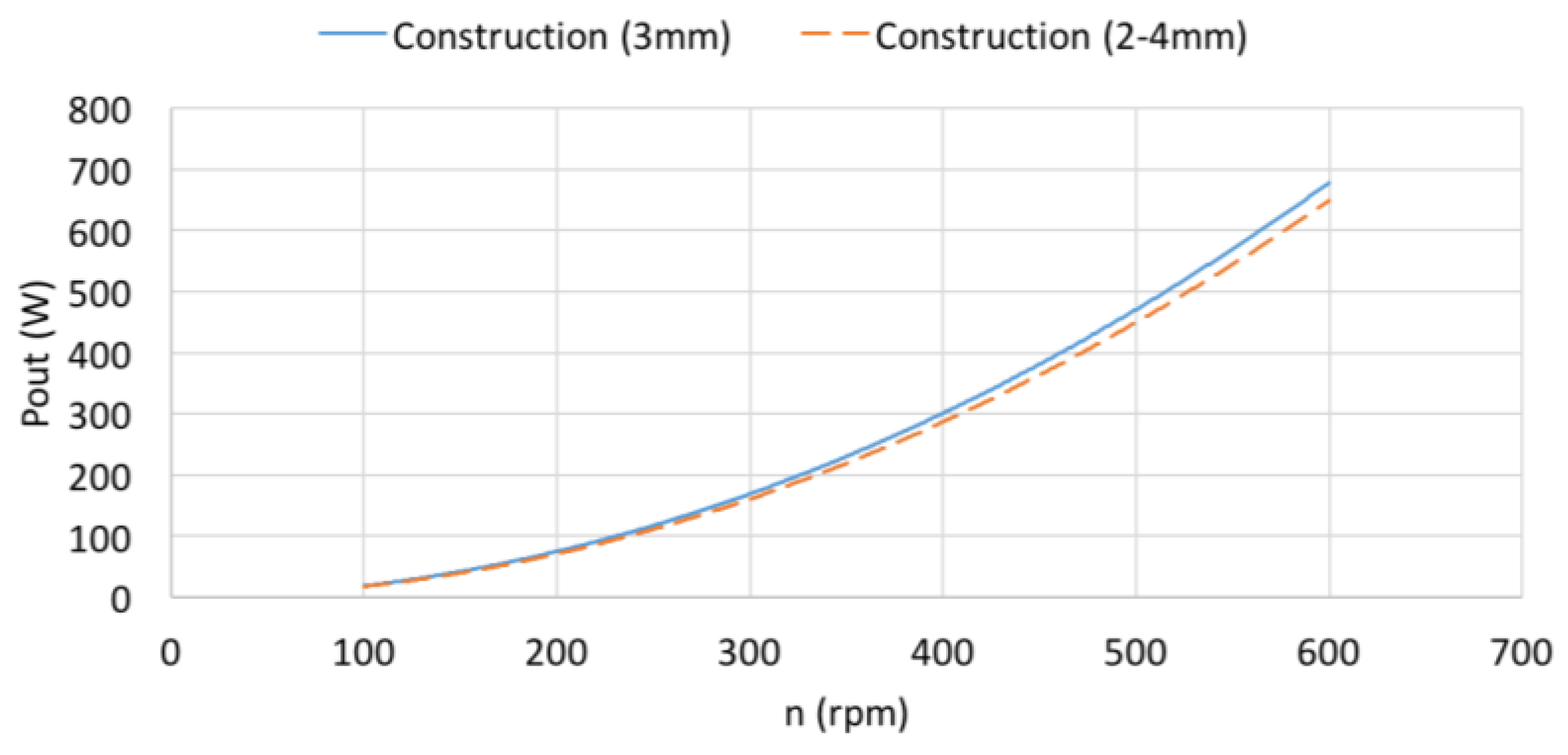
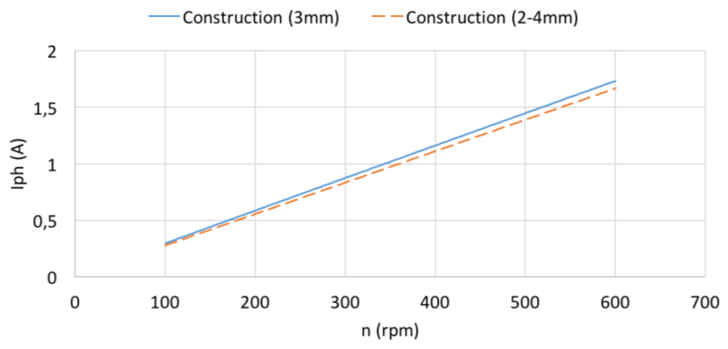
Figure 19 and Figure 20 demonstrate the variation of the phase current and phase voltage under load, respectively, versus the speed for the two air gap cases. The constructed machine with two unequal air gaps presents slightly less current and voltage than the machine with equal air gaps. This explains the similar reduction of the output power in the case of two unequal air gaps, compared to the case of equal air gaps, as presented in Figure 21. Potential causes of the discrepancy between FEM and experimental results are small asymmetries of the constructed machines and the variation of the ohmic resistances with the temperature.
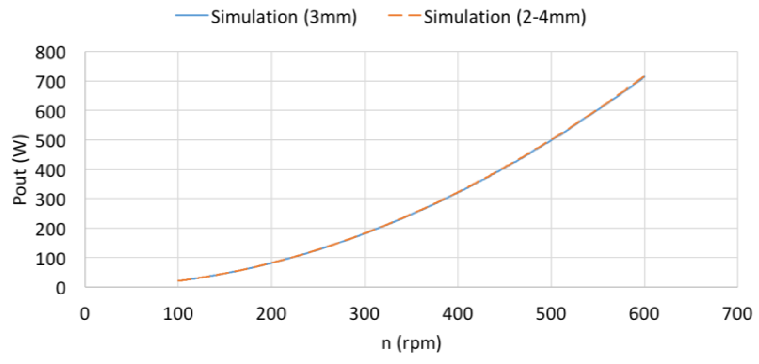
Finally, the ratio (Pout_symmetric − Pout_asymmetric)/Pout_symmetric, describing the influence of the air gap variation, was computed for the same load and a variety of speed values. This ratio is negligible for the simulation results (0.6%, Figure 17), while for the experimental results, Figure 21, it is 4.9%.
6. Conclusions
The objective of this paper was to examine the performance of a low speed, axial flux permanent magnet synchronous generator for small power wind applications. Firstly, the chosen parameters of the AFPM machine were indicated, as well as the calculated variables from the analytical equations. Using nonlinear 3D FEM electromagnetic analysis, the proper magnet topology was selected, as presented in a former published paper, and the model was simulated for a variety of speeds under no-load and load conditions. The prototype was constructed in the university laboratory, investigated and lastly the experimental results were compared to the simulation ones. The comparison indicated that the experimental results confirm the simulation. An experimental temperature test for the prototype stator was performed showing the safe operation of the machine and finally the machine was tested for the two unequal air gaps operating condition. FEM results show that unequal air gaps, maintaining the same total axial width of the machine as the machine with two equal air gaps, do not affect machine Back EMF, the stator current, the terminal voltage and the output power of the machine. Experimental results indicate that unequal air gaps, maintaining the same total axial width of the machine as the machine with two equal air gaps, do not affect machine Back EMF, while the stator current, the terminal voltage and the output power are slightly decreased.
Author Contributions
All authors contributed in every part of the design, experiment, measurements, data analysis and the authorship of this paper.
Conflicts of Interest
There are no conflicts of interests.
References
- Park, Y.-S.; Jang, S.-M.; Choi, J.-H.; Choi, J.-Y.; You, D.-J. Characteristic Analysis on Axial Flux Permanent Magnet Synchronous Generator Considering Wind Turbine Characteristics According to Wind Speed for Small-Scale Power Application. IEEE Trans. Magn. 2012, 48, 2937–2940. [Google Scholar] [CrossRef]
- Christopher, H.; Lee, T.; Liu, C.; Chau, K.T. A Magnetless Axial-Flux Machine for Range-Extended Electric Vehicles. Energies 2014, 7, 1483–1499. [Google Scholar] [Green Version]
- Yang, Y.P.; Shih, G.Y. Optimal Design of an Axial-Flux Permanent-Magnet Motor for an Electric Vehicle Based on Driving Scenarios. Energies 2016, 9, 285. [Google Scholar] [CrossRef]
- Sung, S.-Y.; Jeong, J.-H.; Park, Y.-S.; Choi, J.-Y.; Jang, S.-M. Improved Analytical Modeling of Axial Flux Machine with a Double-Sided Permanent Magnet Rotor and Slotless Stator Based on an Analytical Method. IEEE Trans. Magn. 2012, 48, 2945–2948. [Google Scholar] [CrossRef]
- Caricchi, F.; Crescimbini, F. Modular Axial-Flux Permanent-Magnet Motor for Ship Propulsion Drives. IEEE Trans. Energy Convers. 1999, 14, 673–679. [Google Scholar] [CrossRef]
- Olivier, M.; Rémi, F.; Claude, M.; Yahya, C.; Dominique, C.; Luc, K.; Edouard, B. 3-D–2-D Dynamic Magnetic Modeling of an Axial Flux Permanent Magnet Motor with Soft Magnetic Composites for Hybrid Electric Vehicles. IEEE Trans. Magn. 2014, 50. [Google Scholar] [CrossRef]
- Gieras, J.F.; Wang, R.-J.; Kamper, M.J. Axial Flux Permanent Magnet Brushless Machines; Kluwer Academic Publishers: Dordrecht, The Netherlands, 2004. [Google Scholar]
- Naghi, R.; Reza Feyzi, M.; Juha, P.; Asko, P.; Vahid, B. Genetic Algorithm Approach for Improved Design of a Variable Speed Axial-Flux Permanent-Magnet Synchronous Generator. IEEE Trans. Magn. 2012, 48, 4860–4865. [Google Scholar]
- Aydin, M.; Zhu, Z.Q.; Lipo, T.A.; Howe, D. Minimization of Cogging Torque in Axial-Flux Permanent-Magnet Machines: Design Concepts. IEEE Trans. Magn. 2007, 43, 3614–3622. [Google Scholar] [CrossRef]
- Saeid, J.; Mojtaba, M. Design and Analysis of 42-V Coreless Axial-Flux Permanent-Magnet Generators for Automotive Applications. IEEE Trans. Magn. 2010, 46, 1015–1023. [Google Scholar]
- Krebs, G.; de Cecco, E.; Marchand, C. Design approach of an axial flux motor for electrical powertrain vehicle. In Proceedings of the (ICEM), XXth International Conference on Electrical Machine, Marseille, France, 2–5 September 2012. [Google Scholar]
- Chan, T.F.; Lai, L.L. An Axial-Flux Permanent-Magnet Synchronous Generator for a Direct-Coupled Wind-Turbine System. IEEE Trans. Energy Convers. 2007, 22, 86–94. [Google Scholar] [CrossRef]
- Virtic, P.; Pisek, P.; Marcic, T.; Hadziselimovic, M.; Bojan, S. Analytical Analysis of Magnetic Field and Back Electromotive Force Calculation of an Axial-Flux Permanent Magnet Synchronous Generator with Coreless Stator. IEEE Trans. Magn. 2008, 44, 4333–4336. [Google Scholar] [CrossRef]
- Jin, P.; Yuan, Y.; Jin, M.; Fang, S.; Lin, H.; Hui, Y.; Ho, S.L. 3-D Analytical Magnetic Field Analysis of Axial Flux Permanent-Magnet Machine. IEEE Trans. Magn. 2014, 50. [Google Scholar] [CrossRef]
- Huang, Y.; Ge, B.; Dong, J.; Lin, H.; Zhu, J.; Guo, Y. 3-D Analytical Modeling of No-Load Magnetic Field of Ironless Axial Flux Permanent Magnet Machine. IEEE Trans. Magn. 2012, 48, 2929–2932. [Google Scholar] [CrossRef]
- Amin, M.; Solmaz, K.; Abd Rahim, N.; Wooi, P.H. Design, Analysis, and Prototyping of an Axial-Flux Permanent Magnet Motor Based on Genetic Algorithm and Finite-Element Analysis. IEEE Trans. Magn. 2013, 49, 1479–1492. [Google Scholar]
- Igor, S.; Nikola, M.; Nigel, S.; Mahesh, K.; Ali, E. Design, Analysis, and Optimization of Ironless Stator Permanent Magnet Machines. IEEE Trans. Power Electron. 2013, 28, 2527–2538. [Google Scholar]
- Maloberti, O.; Marchand, C.; Choua, Y.; Condamin, D.; Kobilansky, L.; Bomme, E. Multi-Physical QuasiStatic Modelling of an Axial Flux Permanent Magnet Machine. In Proceedings of the XIX International Conference on Electrical Machines—ICEM, Rome, Italy, 6–8 September 2010. [Google Scholar]
- Seyed, M.H.; Mojtaba, A.-M.; Mehran, M. Design, Prototyping, and Analysis of a Low Cost Axial-Flux Coreless Permanent-Magnet Generator. IEEE Trans. Magn. 2008, 44, 75–80. [Google Scholar]
- Choi, J.-Y.; Lee, S.-H.; Ko, K.-J.; Jang, S.-M. Improved Analytical Model for Electromagnetic Analysis of Axial Flux Machines with Double-Sided Permanent Magnet Rotor and Coreless Stator Windings. IEEE Trans. Magn. 2011, 47, 2760–2763. [Google Scholar] [CrossRef]
- Price, G.F.; Batzel, T.D.; Comanescu, M.; Muller, B.A. Design and Testing of a Permanent Magnet Axial Flux Wind Power Generator. In Proceedings of the IAJC-IJME International Conference, Nashville, TN, USA, 17–19 November 2008. [Google Scholar]
- Kappatou, J.C.; Zalokostas, G.D.; Spyratos, D.A. Design Optimization of Axial Flux Permanent Magnet (AFPM) Synchronous Machine Using 3D FEM Analysis. J. Electromagn. Anal. Appl. 2016, 8, 247–260. [Google Scholar] [CrossRef]
- Huang, S.; Luo, J.; Leonardi, F.; Lip, T.A. A Comparison of Power Density for Axial Flux Machines Based on General Purpose Sizing Equations. IEEE Trans. Energy Convers. 1999, 14, 185–192. [Google Scholar] [CrossRef]
- Kamper, M.J.; Wang, R.-J.; Rossouw, F.G. Analysis and Performance of Axial Flux Permanent-Magnet Machine with Air-Cored Non-overlapping Concentrated Stator Windings. IEEE Trans. Ind. Appl. 2008, 44, 1495–1504. [Google Scholar] [CrossRef]
- Maryam, S.; Naghi, R.; Vahid, B.; Juha, P.; Majid, R. Comparison of Performance Characteristics of Axial-Flux Permanent-Magnet Synchronous Machine With Different Magnet Shapes. IEEE Trans. Magn. 2015, 51. [Google Scholar] [CrossRef]
Figure 1.
The layout of the permanent magnets and the shape of the magnets as upper and lower, respectively. (a) Radial magnets; (b) conventional skew magnets; (c) dual skew magnets; (d) triangular skew magnets.
Figure 1.
The layout of the permanent magnets and the shape of the magnets as upper and lower, respectively. (a) Radial magnets; (b) conventional skew magnets; (c) dual skew magnets; (d) triangular skew magnets.
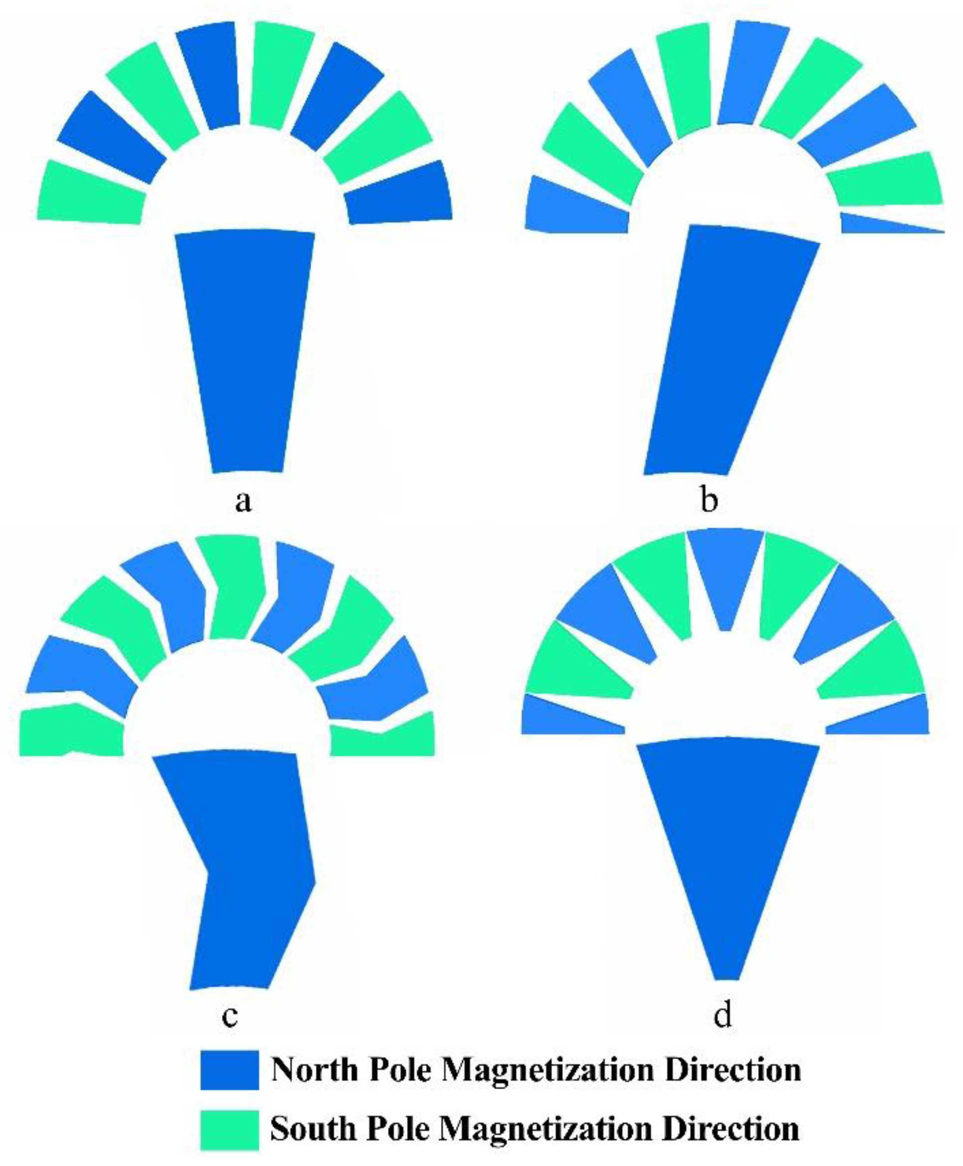
Figure 2.
3D simulated model (exploded preview).

Figure 3.
Magnetic flux distribution in the middle of the air gap in absolute values.

Figure 4.
Plot versus the speed of the Back-EMF, RMS, with 3 mm air gaps, simulation results.
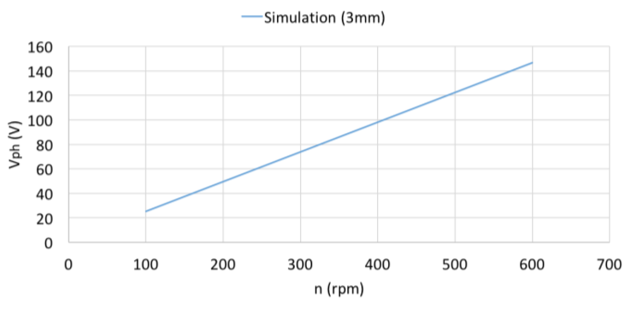
Figure 5.
Plot versus the speed of the power output with 3 mm air gaps, simulation results.
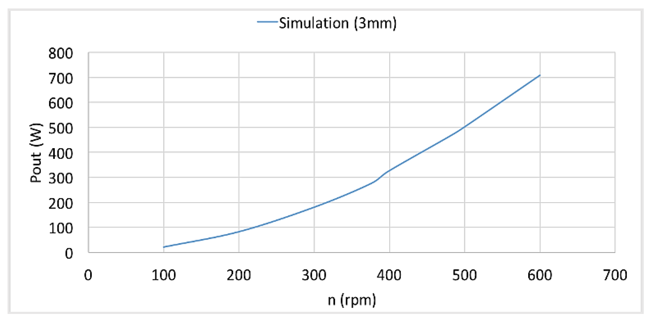
Figure 6.
3D design of the test bench.

Figure 7.
Constructed test bench.

Figure 8.
Line voltage waveform of the AFPMSG at no-load (Back-EMF) for a speed of 300 rpm, as shown in oscilloscope.
Figure 8.
Line voltage waveform of the AFPMSG at no-load (Back-EMF) for a speed of 300 rpm, as shown in oscilloscope.

Figure 9.
Plot versus the speed of the output phase voltage at no-load, simulation and experimental results.
Figure 9.
Plot versus the speed of the output phase voltage at no-load, simulation and experimental results.

Figure 10.
Plot versus the speed of the output power simulation and experimental results at 70 Ω/phase load.
Figure 10.
Plot versus the speed of the output power simulation and experimental results at 70 Ω/phase load.

Figure 11.
Plot versus the load per phase of the output power simulation and experimental results for a speed of 375 rpm.
Figure 11.
Plot versus the load per phase of the output power simulation and experimental results for a speed of 375 rpm.
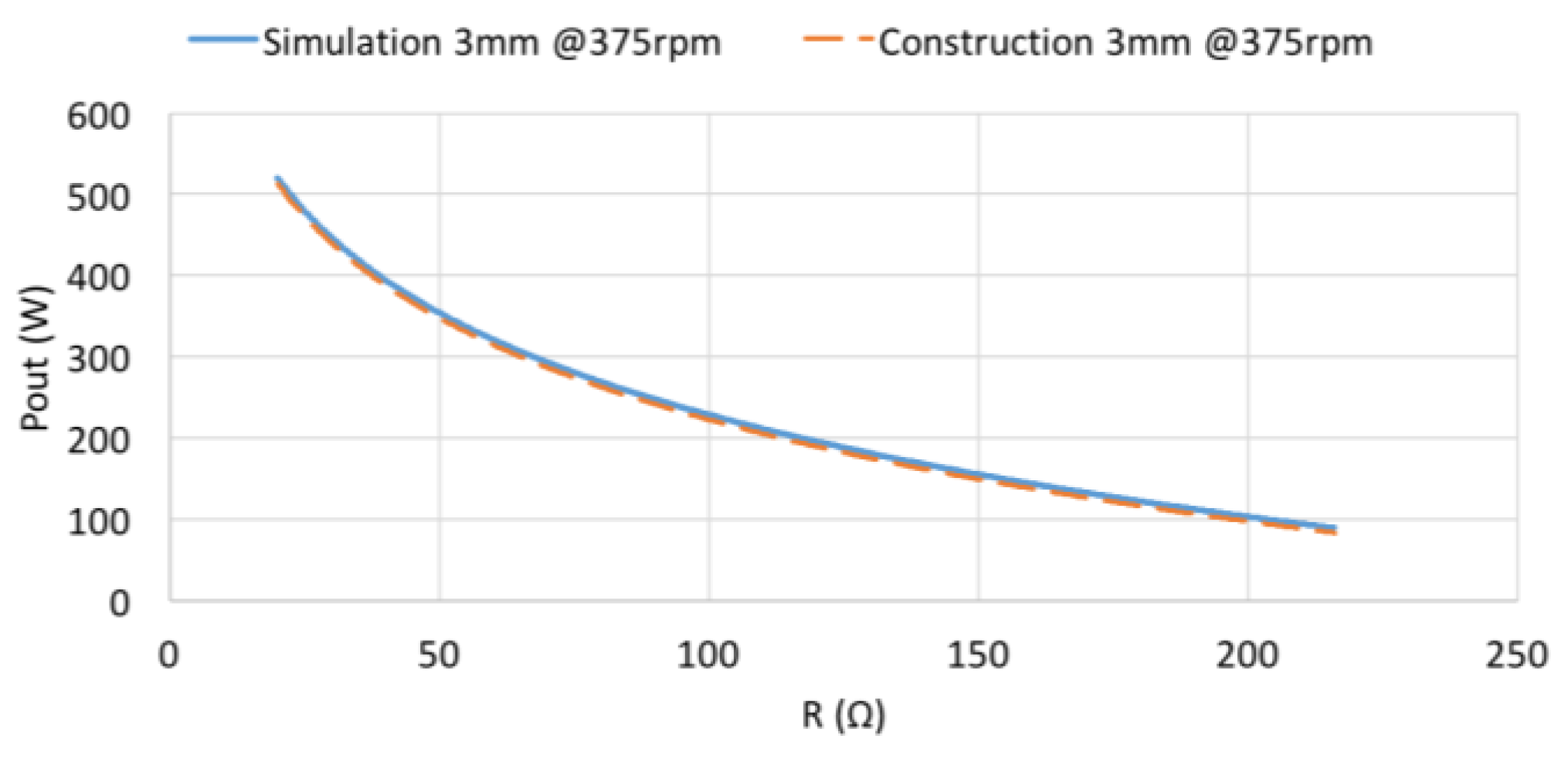
Figure 12.
Plot versus the speed of the output power under 70, 26 and 130 Ω/phase load with 3 mm air gaps, experimental results.
Figure 12.
Plot versus the speed of the output power under 70, 26 and 130 Ω/phase load with 3 mm air gaps, experimental results.

Figure 13.
Constructed stator with the temperature measuring points indicated.

Figure 14.
Temperature test, only stator mounted in the shaft, 2 A dc current to the winding.
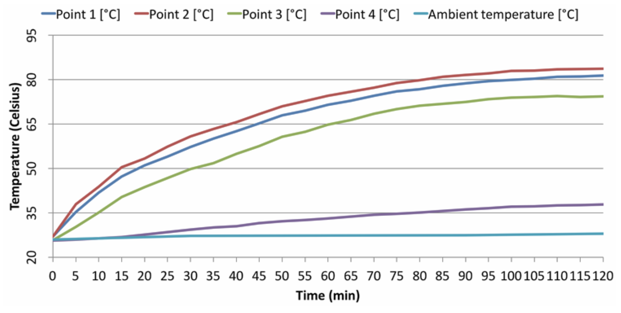
Figure 15.
Normal component of the magnetic density across the axial length of the machine with 3 mm air gaps compared with the 2–4 mm air gaps machine.
Figure 15.
Normal component of the magnetic density across the axial length of the machine with 3 mm air gaps compared with the 2–4 mm air gaps machine.

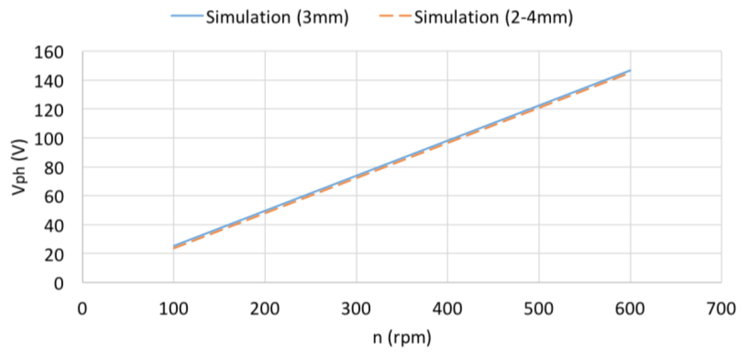
Figure 16.
Plot versus the speed of the output phase voltage at no-load (Back-EMF) in simulation model with 3 mm air gaps compared to that of the simulation model with 2–4 mm air gaps.
Figure 16.
Plot versus the speed of the output phase voltage at no-load (Back-EMF) in simulation model with 3 mm air gaps compared to that of the simulation model with 2–4 mm air gaps.

Figure 17.
Plot versus the speed of the output power in the simulation model with 3 mm air gaps compared to that of the simulation model with 2–4 mm air gaps.
Figure 17.
Plot versus the speed of the output power in the simulation model with 3 mm air gaps compared to that of the simulation model with 2–4 mm air gaps.

Figure 18.
Plot versus the speed of the output phase voltage at no-load in the constructed model with 3 mm air gaps compared to that of the constructed model with 2–4 mm air gaps.
Figure 18.
Plot versus the speed of the output phase voltage at no-load in the constructed model with 3 mm air gaps compared to that of the constructed model with 2–4 mm air gaps.
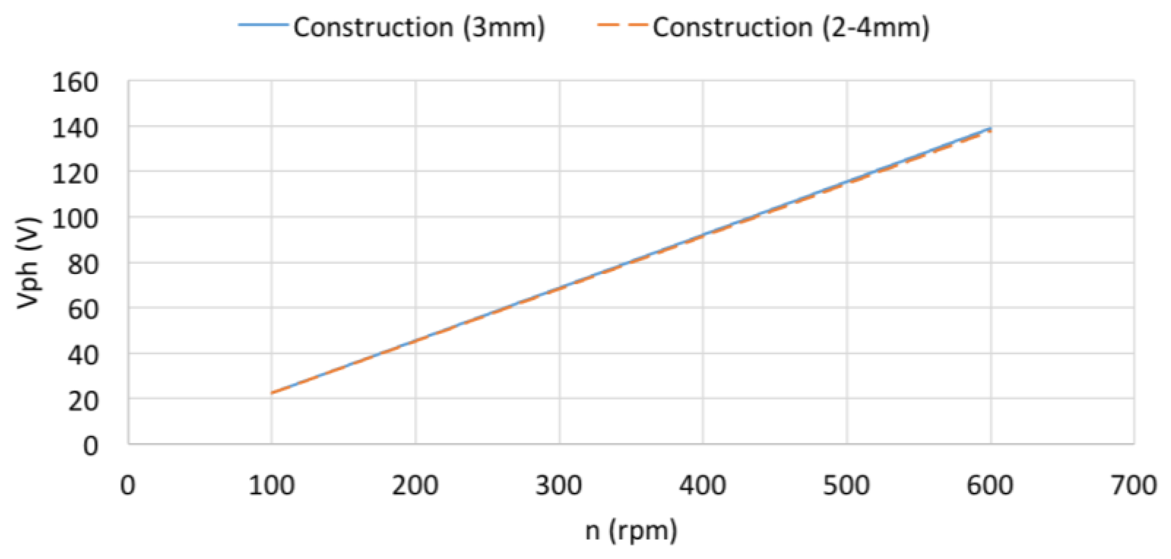
Figure 19.
Plot versus the speed of the output phase current in constructed model with 3 mm air gaps compared to that of the constructed model with 2–4 mm air gaps.
Figure 19.
Plot versus the speed of the output phase current in constructed model with 3 mm air gaps compared to that of the constructed model with 2–4 mm air gaps.

Figure 20.
Plot versus the speed of the terminal phase voltage in constructed model with 3 mm air gaps compared to that of the constructed model with 2–4 mm air gaps.
Figure 20.
Plot versus the speed of the terminal phase voltage in constructed model with 3 mm air gaps compared to that of the constructed model with 2–4 mm air gaps.

Figure 21.
Plot versus the speed of the output power in constructed model with 3 mm air gaps compared to that of the constructed model with 2–4 mm air gaps.
Figure 21.
Plot versus the speed of the output power in constructed model with 3 mm air gaps compared to that of the constructed model with 2–4 mm air gaps.

Table 1.
Basic machine parameters.
| Parameter | Value |
|---|---|
| Number of poles in one rotor | 16 |
| Nominal frequency | 50 Hz |
| Rotor axial thickness | 12 mm |
| Magnet axial thickness | 10 mm |
| Air-gap axial thickness | 3 mm |
| Internal to external radius ratio (σ) | 0.379 |
Table 2.
Calculated variables from the theoretical equations.
| Parameter | Value |
|---|---|
| Number of coils | 12 |
| Stator axial thickness | 18 mm |
| Stator external radius | 158 mm |
| Stator internal radius | 60 mm |
| Number of turns per coil | 210 |
| Nominal number of revolutions | 375 rpm |
© 2017 by the authors. Licensee MDPI, Basel, Switzerland. This article is an open access article distributed under the terms and conditions of the Creative Commons Attribution (CC BY) license (http://creativecommons.org/licenses/by/4.0/).
Share and Cite
MDPI and ACS Style
Kappatou, J.C.; Zalokostas, G.D.; Spyratos, D.A. 3-D FEM Analysis, Prototyping and Tests of an Axial Flux Permanent-Magnet Wind Generator. Energies 2017, 10, 1269. https://doi.org/10.3390/en10091269
AMA Style
Kappatou JC, Zalokostas GD, Spyratos DA. 3-D FEM Analysis, Prototyping and Tests of an Axial Flux Permanent-Magnet Wind Generator. Energies. 2017; 10(9):1269. https://doi.org/10.3390/en10091269
Chicago/Turabian StyleKappatou, Joya C., Georgios D. Zalokostas, and Dimitrios A. Spyratos. 2017. "3-D FEM Analysis, Prototyping and Tests of an Axial Flux Permanent-Magnet Wind Generator" Energies 10, no. 9: 1269. https://doi.org/10.3390/en10091269
Note that from the first issue of 2016, this journal uses article numbers instead of page numbers. See further details here.