Interconnecting Microgrids via the Energy Router with Smart Energy Management

School of Electrical and Information Engineering, Tianjin University, Tianjin 300072, China
*
Author to whom correspondence should be addressed.
Energies 2017, 10(9), 1297; https://doi.org/10.3390/en10091297
Submission received: 14 July 2017
/
Revised: 26 August 2017
/
Accepted: 28 August 2017
/
Published: 30 August 2017
(This article belongs to the Special Issue Energy Storage Systems and Power Conversion Electronics for E-Transportation and Smart Grid)
Abstract
:A novel and flexible interconnecting framework for microgrids and corresponding energy management strategies are presented, in response to the situation of increasing renewable-energy penetration and the need to alleviate dependency on energy storage equipment. The key idea is to establish complementary energy exchange between adjacent microgrids through a multiport electrical energy router, according to the consideration that adjacent microgrids may differ substantially in terms of their patterns of energy production and consumption, which can be utilized to compensate for each other’s instant energy deficit. Based on multiport bidirectional voltage source converters (VSCs) and a shared direct current (DC) power line, the energy router serves as an energy hub, and enables flexible energy flow among the adjacent microgrids and the main grid. The analytical model is established for the whole system, including the energy router, the interconnected microgrids and the main grid. Various operational modes of the interconnected microgrids, facilitated by the energy router, are analyzed, and the corresponding control strategies are developed. Simulations are carried out on the Matlab/Simulink platform, and the results have demonstrated the validity and reliability of the idea for microgrid interconnection as well as the corresponding control strategies for flexible energy flow.
1. Introduction
Increasing amounts of distributed renewable energy sources (RESs), such as solar and wind, are expected to be integrated into the power system to meet the ever-growing energy demand, and more importantly, to meet the need to preserve fossil fuel resources. As a result, the existing electrical power grid will be experiencing a shift from the traditional single-sourced, radial framework network to the multi-sourced, meshed network of the next generation—the Internet of Energy (IOE) [1,2,3,4]. However, as the demand keeps rising for higher penetration of RESs, there are many technical challenges yet to be overcome [5]. One of them is that existing technologies rely heavily on energy storage (ES) systems to maintain instant power balance and minimize the impact to the power grid due to the intermittent nature of the RES outputs [6,7,8,9]. Unfortunately, the costs of ES units (such as batteries) still remain high and are not yet economically practical for large scale deployment [10]. For example, the capital cost of lithium-ion batteries for microgrid and residential implementations are up to $1000 and $1500 per kWh, respectively [11]. Besides batteries, there are other types of energy storage technologies such as the flywheel, pumped hydro power, compressed air [12], vehicle-to-grid [13] and power-to-gas [14]. Each technology has unique features, but none of them can meet all the requirements of being robust, reliable and economically competitive [15,16,17]. Therefore, there is a need to develop flexible and sophisticated energy management strategies as a way of maintaining the energy balance and operational stability of the power system, and to alleviate the dependency on large-scale energy storage units for the time being.
Owing to technical advances in the fields of power electronics and communication, in recent years, research on intelligent and multi-functional energy converter—the energy router (ER)—has been booming rapidly [18,19,20,21]. With the functionalities of flexible power flow control and wide area information interaction, the energy router has demonstrated great potential to serve as the “energy hub” in the Internet of Energy. More encouragingly, it is now technically and economically feasible for the energy router to serve as the “energy and information sink node” at the levels of the microgrid [22] and home-area network [23,24], by providing multiple functionalities: (1) working as a smart electrical interface, by enabling flexible, adjustable and bidirectional energy flow between the microgrid and the power grid [25,26]; (2) facilitating optimal energy management within the microgrid and improving the efficiency, reliability and economy of the system [22]; and (3) enabling wide-area data collection from various devices (including RESs, electric equipment and loads) in real time, and providing these data to the control center of the microgrid or to the main grid for load forecasting [27], operational status monitoring [28] and fault diagnosis [29,30]. With all these functionalities, the energy router is naturally considered to be a perfect candidate to deploy flexible and sophisticated energy management strategies.
This paper elaborates on a novel and flexible interconnecting framework for microgrids, and corresponding energy management strategies are presented, in response to the situation of increasing renewable energy penetration and the need to alleviate dependency on energy storage equipment. Different from the traditional manner of connection, this framework distinguishes itself by interconnecting the main grid and multiple microgrids via the energy router, and enabling flexible energy exchange among them.
The key idea is proposed based on the following considerations: (1) microgrids serving different purposes may differ substantially in terms of network architecture, type of RESs and loads within them; and therefore, their energy profiles of power production and consumption of the day may also differ; (2) this difference in the profiles of energy production and consumption usually leads to “complementarities” in their time periods of peak and valley demand. These complementarities can thus be utilized to compensate for each other’s instant energy deficiency. For example, residential areas with rooftop solar energy will have an energy surplus during the day and peak demand in the evening, while commercial or office areas have different peak times of power consumption. If their locations are adjacent, it would definitely be beneficial for both communities if the surplus energy from the rooftop solar supply can be transferred to the areas in short energy supply. It is also beneficial to the main grid, since excessive solar power injections into the distribution network will lead to overvoltage in low voltage (LV) feeders [31]. Therefore, in comparison to the existing microgrid control methods, the work of this paper is focused on a novel framework to establish electrical interconnection and energy trade between microgrids. This work also presents a new paradigm to utilize direct energy consumption to suppress the impact of DER output fluctuations on the stability and reliability of the power system.
The rest of the paper will be arranged as follows: the analytical model is established for the whole system including the interconnected microgrids and the main grid, as well as the energy router, which is based on multiport bidirectional VSCs and a shared DC power line. Various operational modes of the interconnected microgrids facilitated by the energy router are analyzed, and corresponding control strategies are developed. Simulations are carried out on the Matlab/Simulink (R2014b, MathWorks, Natick, MA, USA) platform to demonstrate the validity and reliability of the presented interconnection framework and the corresponding energy control strategies.
2. Energy Router-Based Interconnecting Framework for Microgrids
The energy router-based framework for microgrid interconnection is demonstrated in Figure 1, where the energy router serves as an energy hub to establish electrical connections between the microgrids and the main grid. Its beneficial effects include: (1) the problem of instant energy surplus or deficiency can be resolved with “complementary” energy exchanges between the adjacent microgrids, thus relieving dependency on large-scale energy storage deployment. The impacts caused by the uncertainties and intermittencies of the DER outputs to the microgrid system, and also to the main grid, can further be alleviated to some extent; (2) the VSC converters and shared DC bus facilitate electrical isolation (in voltage, frequency and phase angle) between the microgrids and the main grid [32]. Each microgrid can have "stand-alone" voltage, frequency and phase angle according to its own operational situation, savingefforts for synchronization with the power grid or the other microgrids; (3) this isolation ensures that any voltage or frequency fluctuation at one end of the energy router (either on the microgrid side or the main grid side) will have no direct impact on the systems on other sides of the energy router, thus guaranteeing power quality and operation reliability; and (4) widespread implementation of the energy routers will promote the shift of the power system architecture from the traditional “tree-structure” hierarchical framework to a more connective and interactive framework. This final consequence will help to improve the power supply quality and the reliability of the whole system, which is an essential step in building the Internet of Energy of the future.
As shown in Figure 2, the schematic of the power router is based on multiport bidirectional voltage source converters (VSCs) and a shared DC power line. In this paper, we instigate the implementation of a three-port schematic—one port for connection to the main grid, and the other two for interconnections to adjacent microgrids. The VSCs in each port can operate in either rectifier or inverter mode, thus enabling bi-directional power flow control between the alternating current (AC) and shared DC power lines.
With the DC power line serving as an “energy pool”, autonomous energy trade can be performed between the interconnected microgrids without the intervention of the VSC on the main grid side. Energy flow management is easy and flexible, enabled by the multiport energy router. Besides the existing tied and islanded operational modes, there will be a new operational mode for the microgrids—the Parallel Mode. This will happen when a microgrid is having energy exchange (either input or output) only with the adjacent microgrid. For example, a microgrid providing excessive energy to its neighboring microgrid is working in the parallel mode; it does not have any energy exchange with the main grid, even when the VSC on the grid side is still in operation.
The various operational modes enabled by the energy router are demonstrated in Figure 3. According to the energy flow indicated in this figure, the operational modes of each microgrid can be summarized as:
- (1)
- as for the case in Figure 3a, both microgrid 1 and microgrid 2 are taking energy from the main grid, as the direction of power flow is from power grid to the microgrids. In this situation, both microgrid 1 and microgrid 2 are operating in the grid-connected mode;
- (2)
- as for the case in Figure 3b, microgrid 1 can be self-sufficient while microgrid 2 is taking energy from the main grid, as the direction of power flow is only from the power grid to microgrid 2. In this situation, microgrid 1 is operating in the islanded mode while microgrid 2 is operating in the grid-connected mode;
- (3)
- as for the case in Figure 3c, microgrid 1 is taking energy from both the main grid and microgrid 2, while microgrid 2 can not only operate on its own energy production, but provides surplus power to microgrid 1 as well. The direction of power flow is from both the main grid and microgrid 2 to microgrid 1. In this situation, microgrid 1 is operating in the grid-connected mode, while microgrid 2 is operating in the parallel mode;
- (4)
- as for the case in Figure 3d, microgrid 1 is providing surplus power to microgrid 2, while no power needs to be transferred from the main grid to the DC power line. The direction of power flow is from microgrid 1 to microgrid 2. In this situation, both microgrid 1 and microgrid 2 are operating in the parallel mode.
3. Topology and Mathematical Model of the Energy Router
3.1. Topology of the Energy Router
The topology of the energy router considered in this paper is shown in Figure 4. In practice, it can be regarded as a tri-port energy converter that comprises three VSCs with their RLC filters and a shared common DC power line.
Let VSCi (i = 0, 1, 2) represent the VSCs of the energy router, in which VSC0 is on the power grid side, while VSC1 and VSC2 are on the microgrid side. Assume that the VSCs and the corresponding RLC filters are three-phase symmetry circuits. As shown in Figure 4, eabci and iabci (i = 0, 1, 2) are the three-phase voltages and currents on the AC side, k is the transformer ratio, Ci = Cai = Cbi = Cci are the single-phase capacitance of the RLC filters, Li = Lai = Lbi = Lci are the single-phase inductance of the RLC filters, Ri = Rai = Rbi = Rci are the equivalent single-phase resistance of the RLC filters, vabci are the three-phase output voltage of the VSCi, Cdc is the capacitance of the DC power line, udc is the DC-link voltage and idci is the DC current flowing in or out of the VSCi.
3.2. Analytical Model of the Energy Router
Because the VSC on the main grid side shall be working in a different pattern from the VSCs on the microgrid side, the model of the VSCs shall be described differently. According to the operation modes enabled by the energy router, as shown in Figure 3, VSC0 only works in the rectifier status, whereas VSC1 and VSC2 can work in either the rectifier or inverter statuses (which should be described by different model representations). Hence, the case in Figure 3c is taken as an example to formulate the state-space representations of the VSCs. In this situation, VSC0 and VSC2 work as rectifiers, and VSC1 works as an inverter.
The uni-polar logic switching function sj is defined as:
Then, the three-phase circuit equations of the VSC0 are established and transformed into the dq rotating coordinate system, as shown in the following equations:
in which LΣ = LT + L0 is the equivalent inductance on the AC side of VSC0, LT is the equivalent inductance of the transformer, idi and iqi are the components of iabci in the d and q axes, ωi is the angular frequency of the AC system, edi and eqi are the components of eabci in the d and q axes, k is the transformer ratio, and sdi and sqi are the components of the switching function in the d and q axes of the dq rotating coordinate system.
The current flowing in or out of the VSCi can be calculated by:
The current balance equation of the DC power line is:
Substituting Equation (3) into Equation (4), Equation (5) can be derived:
Similarly, the mathematical models of the VSC1 working in the inverter status and VSC2 working in the rectifier status can be derived as:
Equations (2) and (5)–(7) constitute the analytical model of the energy router in the situation represented in Figure 3c, in which the microgrid 1 is in the grid-connected mode and microgrid 2 in the parallel mode. Models of the energy router operating in the other situations represented in Figure 3 can also be derived in the same way.
4. Energy Control Strategies of the Energy Router
4.1. Control Schematic of the VSCs
The VSCs in the energy router are under dual-loop control, and the controller structure of the VSCs is shown in the Figure 5.
The dual-loop controller mainly consists of four modules: (1) the inner-loop controller, also known as the current feedback loop; (2) the outer-loop controller, which can either be a DC voltage controller or an active/reactive power controller, depending on the control objective of each VSC; (3) the phase-locked loop (PLL), which can be used to obtain the phase angle of the AC voltage for Park’s Transformation; and (4) the pulse width modulation (PWM) controller.
4.2. Control Patterns for the VSCs
The VSCs of the energy router are working in the master/slave mode. For the master VSC, its outer-loop controller shall be working as the DC voltage controller, with its goal being to maintain stable and constant DC-link voltage. The rest of the VSCs shall be the slave converters, working in the manner of power transfer following up. Their out-loop controllers shall be working as the active/reactive power controllers, with the goal being to keep their power transfer following up the needs of the microgrids in connection.
The rules to choose the master converter are thus: (1) when the main grid is involved in power transfer, VSC0 is preferred as the master converter and the VSCs on the microgrid side are the slave converters; (2) when the main grid is not involved in energy exchange, the master converter shall be the VSC in connection with the microgrid which provides energy to its neighbor, while the VSC which intakes energy shall be the slave converter.
As defined in Table 1, there are three control patterns for the VSCs according to the operational status of their inner- and outer-loop controllers. The various operational modes of the microgrids are realized by choosing appropriate control patterns for the VSCs, which will also determine the roles of the VSCs (master or slave) in the process of power flow. For the master converter, the outer-loop controller shall be working as the DC voltage controller while the inner-loop controller will keep the H-bridge of the converter working in the rectifier status. Thus, the master converter should be working in control pattern 1. Meanwhile, a slave converter can be selected to work in either pattern 2 or pattern 3, according to the role it plays in the process of power flow. In other words, the control pattern of a VSC is determined by the operational mode of the microgrid in connection with it.
The control patterns of the VSCs can be listed as follows:
- (1)
- once the main grid is involved in power transfer, VSC0 is chosen to be the master converter, working in pattern 1;
- (2)
- for a microgrid working in the grid-connected mode, the VSC beside the power grid must be working in pattern 3;
- (3)
- for a microgrid working in the parallel mode, the corresponding control pattern of its VSC is determined according to the other microgrid’s operational mode. For example, when microgrid 2 works in parallel mode and microgrid 1 is in the grid-connected mode, which corresponds to the case represented in Figure 3c, VSC2 must be working in pattern 2, because the surplus energy of microgrid 2 is transferred to the DC power line through it;
- (4)
- when both microgrid 1 and microgrid 2 are in parallel mode, as in Figure 3d, VSC2 is working in pattern 3 and VSC1 is working in pattern 1, because the direction of energy flow is from microgrid 2 to microgrid 1.
4.3. Control Patterns for the Energy Router
For the RESs, ESs and loads in the microgrids, the required active power of microgrid 1 and microgrid 2 can be calculated by:
where the DG outputs in microgrid 1 and microgrid 2 are denoted by PDG1 and PDG2, the energy stored in ESs are Pbat1 and Pbat2, and power demand from the loads are Pload1 and Pload2, respectively.
The total sum of active power for microgrid 1 and microgrid 2 is denoted by PMG. When the power grid is involved in the energy exchange, the supplied power denoted by P0 is:
5. Dual-Loop Feedback Control
5.1. Inner Loop Controller
Based on Kirchhoff’s law, the voltage equation of VSC0 in the synchronous dq coordinate system can be derived, and the items coupling between the d and q axes can be removed by the decoupling feed forward control method. Assuming that the energy router operates in case 3 (in Figure 3c), the voltage control equations of the VSCi inner-loop controller can be written as:
where KPi and KIi are the proportional and integral regulation gain in the inner loop, respectively.
Similarly, the voltage equation of VSC1 working in the inverter status can be written as:
while the voltage equation of VSC2 working in the rectifier status can also be derived as:
5.2. Outer-Loop Controller
The outer-loop is used to generate the inner-loop current reference signal and input to the inner-loop control. According to different control objectives, the outer-loop controller can be classified as active/reactive power controller or DC voltage controller.
5.2.1. Active/Reactive Power Controller
The active/reactive power controller is used to keep the VSC working such that its active/reactive power output on the AC side shall follow the reference command value issued by the microgrid controller, with zero steady-state error. Classical proportional-integral (PI) regulators are used in the outer-loop control to calculate the current commands to the inner-loop with the power deviations.
Define the power direction symbol function sgn as:
The d-axis is in the same direction to the voltage vector, which leads to eqi = 0. The active power Pi and reactive power Qi, absorbed from the AC system to VSCi, can be expressed as:
According to Equation (15), the control between active power and reactive power can be decoupled. Then, Pi and Qi are compared with their reference inputs Piref and Qiref, respectively, and the result of the comparison is used by the PI controller to calculate the current command value. The control structure of the active power controller is shown in Figure 7.
As a matter of fact, when the AC systems are injected with excessive power, the corresponding AC voltage ei will rise. Conversely, the corresponding AC voltage will decline when the AC systems lack power energy. Hence, compared to the ordinary zero steady-state error tracking control, AC voltage-limiting controllers are added so that the internal stability of the AC systems can be maintained.
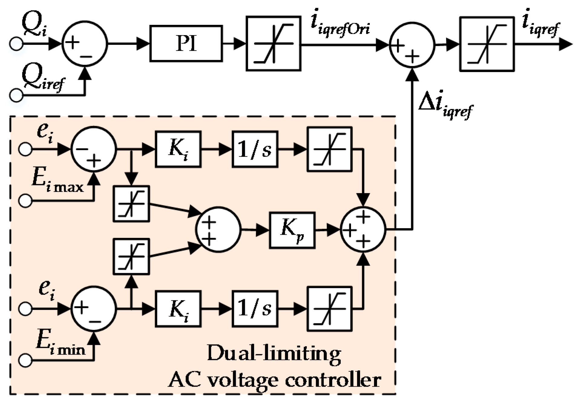
The purpose of the AC voltage-limiting controller is to keep the amplitude of AC voltage within a set range. When ei exceeds the upper-limit value Eimax, the AC voltage-limiting controller outputs a negative value, which serves as the disturbance quantity and adds to the Qiref. Thereby, the inner-loop current command value iiqref decreases, so that the absorbed power in the AC system can be reduced. On the other hand, when ei exceeds the lower-limit value Eimin, the AC voltage-limiting controller outputs a positive value and adds to the Qiref. Thus, the inner-loop current command value iiqref increases, so that the absorbed power in the AC system can be augmented. The control structure of reactive power control within the AC voltage controller is shown in Figure 8.
5.2.2. DC Voltage Controller
The DC voltage controller is responsible for keeping the DC-link voltage within an adequate range around the command value issued by the microgrid controller. For VSCi (i = 1, 2) controlled by the DC voltage controller, the active power Pi exchanged with the AC systems is identical to the DC power Pdc stored in Cdc.
The current command input to the d-axis of the inner-loop current controller is
where KPdc and KIdc are the proportional and integral regulation gains, respectively. Under this controller, the d-axis current command is derived from Equation (17), and the control structure is shown in Figure 9. Meanwhile, the q-axis current command is derived from Equation (15), while the control structure is shown in Figure 8.
6. Simulation Studies
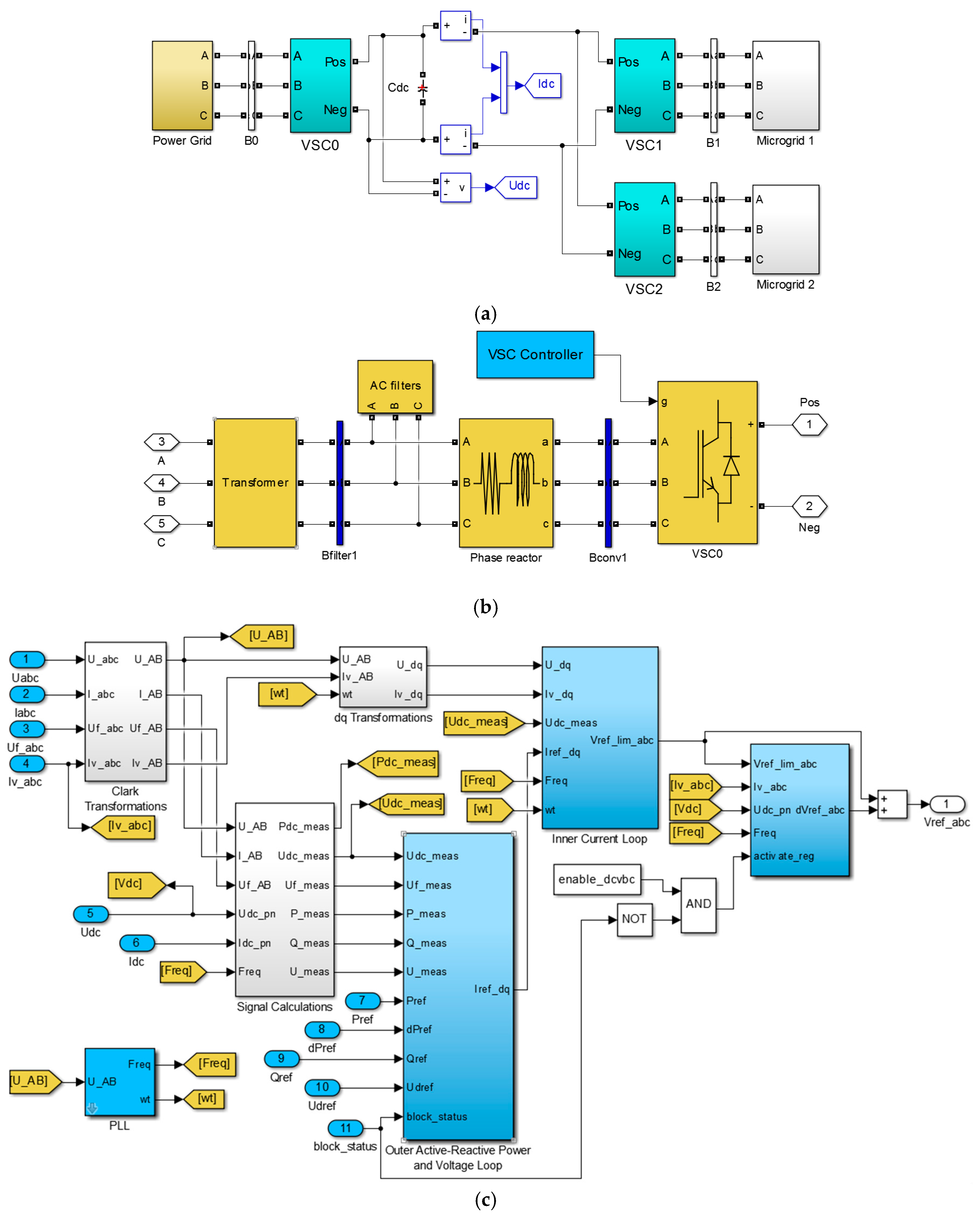
The simulation model of the interconnected microgrid system was built on the MATLAB R2014b/Simulink platform. The simulation model of the overall system and the sub-models of VSC0 and its controller are demonstrated in Figure 10a–c, respectively. Apart from the transformer, the simulation models of VSC1, VSC2 and their controllers are similar to VSC0.
In this section, four simulation scenarios are presented to investigate the dynamic characteristics of the interconnected microgrids in all the operation modes defined previously, and to verify the feasibility of the proposed control strategies. The transient responses of the energy router for operational-mode shifting of the microgrids, the power balancing in Parallel Mode and the suppression of AC voltage disturbances are all demonstrated by these four simulated scenarios. The simulation parameters are listed in Table 4.
6.1. Scenario 1
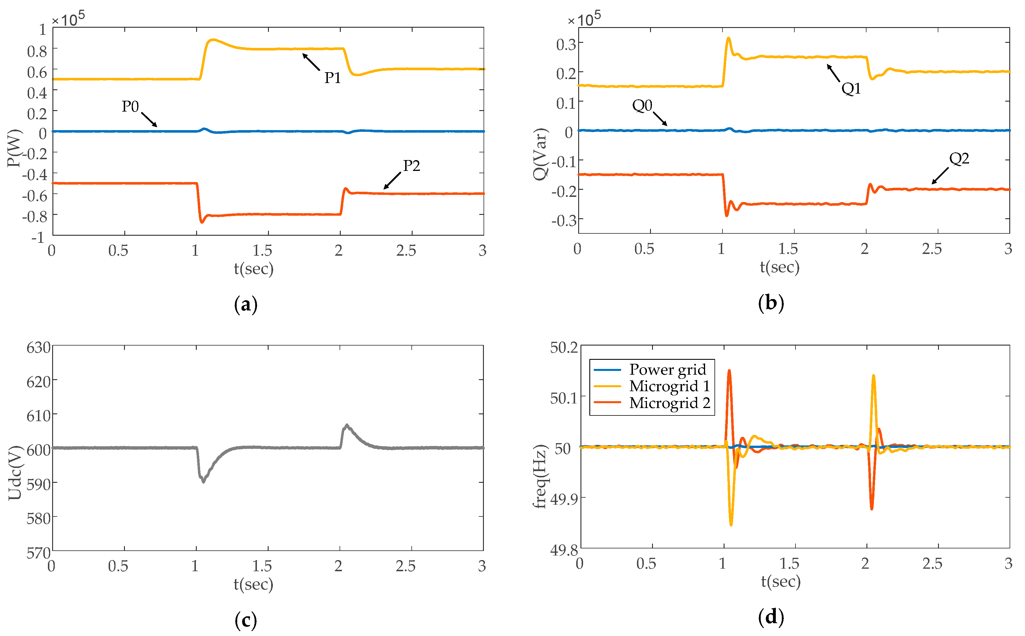
In this paper, a new operational mode—the Parallel Mode—is defined for the interconnected microgrids. Microgrid 2 does not need to have any energy exchange with the power grid, because its power deficit can be met by the surplus power of the adjacent microgrid 1. In this scenario, both microgrid 1 and microgrid 2 are operating in the parallel mode, which the energy router is operating in case 4. Microgrid 1 is supplying its surplus energy to microgrid 2, so VSC1 is the master converter and VSC2 is the slave converter. The detail of the power flow from microgrid 1 to microgrid 2 and the DC-link voltage variation of the transient process are demonstrated in Figure 11.
(1) The process of active power flow within the interconnected microgrids is as follows:
t = 0 s, 50 kW active power is provided to microgrid 2 by microgrid 1; t = 1 s, the active power transfer from VSC1 to VSC2 increases from 50 to 80 kW; t = 2 s, the command value of the active power transfer changes from 80 to 60 kW. The active power variations of the VSCs and the command value curves are shown in Figure 11a.
(2) The reactive power flow between the interconnected microgrids is as follows:
t = 0 s, 15 kVar reactive power is provided to microgrid 2 by microgrid 1; t = 1 s, the absorbed reactive power command value changes from 15 to 25 kVar; t = 2 s, the reactive power transfer changes from 25 to 20 kVar. The reactive power variations of the VSCs and the command value curves are shown in Figure 11b.
As demonstrated in Figure 11a,b, when the power transfer command value changes abruptly at t = 1 s and t = 2 s, there are only slight fluctuations in the output power curves, and the stable state is restored quickly. The active and reactive power transfer of VSC0 remains zero as the main grid is not involved in any power transfer through the energy router. As is shown in Figure 11c, the fluctuation range of the DC-link voltage is minor and can be ignored. Figure 11d shows that frequency fluctuates in an acceptable range for both microgrid 1 and microgrid 2 at the moments that energy exchange occurs. However, due to the electrical isolation of the energy router, the fluctuation does not have an impact on the frequency of the power grid, which remains stable at 50 Hz during the whole process. Note that the DC-link voltage is an indicator of instant power balance; the simulation results in Figure 11 have clearly verified the effectiveness of the control strategies in this scenario.
6.2. Scenario 2
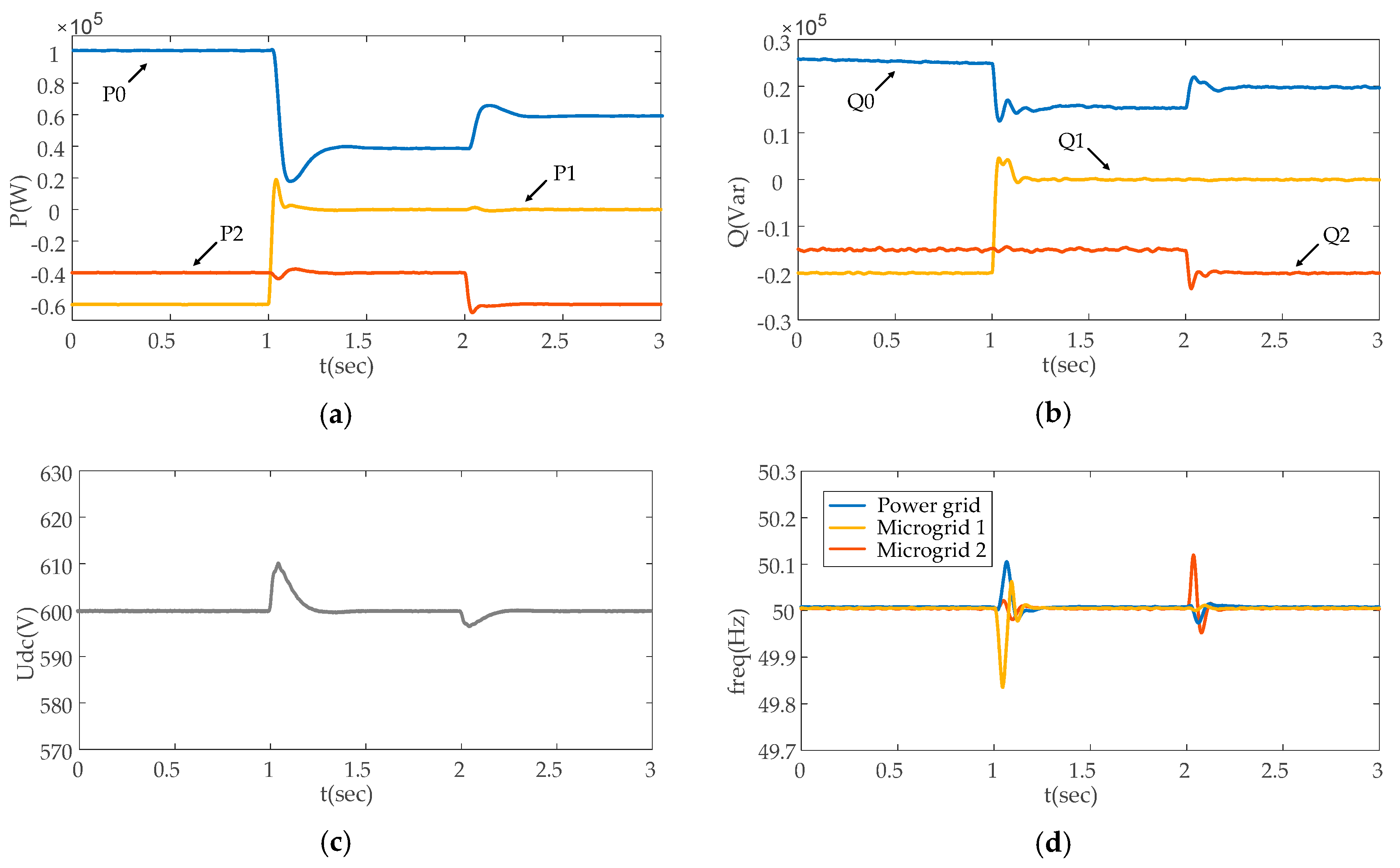
This scenario demonstrates the dynamic characteristics of the interconnected microgrids during the transition process from the situation of case 1 (shown in Figure 3a) to case 2 (in Figure 3b), during which microgrid 1 switches from grid-connected mode to islanded mode, while microgrid 2 remains grid connected. The variations in power flow and AC frequency, as well as the DC-link voltage during the whole process, are demonstrated in Figure 12.
• t = 0–1 s
The energy router is working under the situation of case 1 (shown in Figure 3a). Both microgrid 1 and microgrid 2 are operating in the grid-connected mode, during which VSC0 serves as the master converter while VSC1 and VSC2 work as slave converters. During this period, the active power transferred from VSC0 to both VSC1 and VSC2 is 60 and 40 kW, respectively, and the reactive power transferred to VSC1 and VSC2 is 20 and 15 kVar, respectively.
• t = 1–2 s
The operational situation of the energy router switches to case 2 (shown in Figure 3b). During this period, the operational mode of microgrid 1 is changed from grid-connected to islanded, and VSC1 is not involved in any energy-exchange process. Meanwhile, the operational mode of microgrid 2 remains unchanged, with VSC0 serving as the master converter and VSC2 working as the slave converter. The active and reactive power transferred from the power grid to microgrid 2 remains unchanged.
• t = 2–3 s
In this period, the energy router is operating in the situation of case 2 (shown in Figure 3b), and the active power and reactive power imported from the power grid to microgrid 2 increases to 60 kW and 20 kVar, respectively.
As is shown in Figure 12a,b, the active and reactive power flows can track their command value accurately and rapidly after a small fluctuation. Instant power balance between the power grid and the interconnected microgrids is guaranteed in this case, which has verified the effectiveness of the presented control strategies. The active and reactive power transfer from VSC1 remains zero when microgrid 1 is not involved in the energy exchange. Shown in Figure 12c, the fluctuation range of the DC-link voltage at the moments of power transfer is minor and can be ignored. As for the frequency curves shown the Figure 12d, it can be seen that the frequencies of the power grid and microgrid 2 appear to be fluctuant at the moments that power exchange occurs. However, there is no frequency fluctuation of microgrid 1 at t = 2 s, since that microgrid was not involved in the energy exchange at that moment. The simulation results in Figure 12 have clearly verified the effectiveness of the control strategies in this scenario. Meanwhile, the feasibility of the control scheme in the island mode can also be verified.
6.3. Scenario 3
The microgrid with surplus power production (microgrid 2 in this scenario) may change from grid-connected to parallel mode, while the energy router needs to shift to the situation of case 3. In this scenario, operation of the energy router is switched from the situation of case 1 (shown in Figure 3a) to case 3 (in Figure 3c).The power flow from microgrid 1 to microgrid 2, the DC-link voltage and the AC frequency variations during the whole process are demonstrated in Figure 13.
At t = 1 s, the status of microgrid 2 changes from energy consumption to energy production. Along with the power grid as energy provider, microgrid 2 transfers 20 kW active power and 5 kVar reactive power to microgrid 1. The situation of curve variations in Figure 13 is similar to that in Figure 12.
6.4. Scenario 4
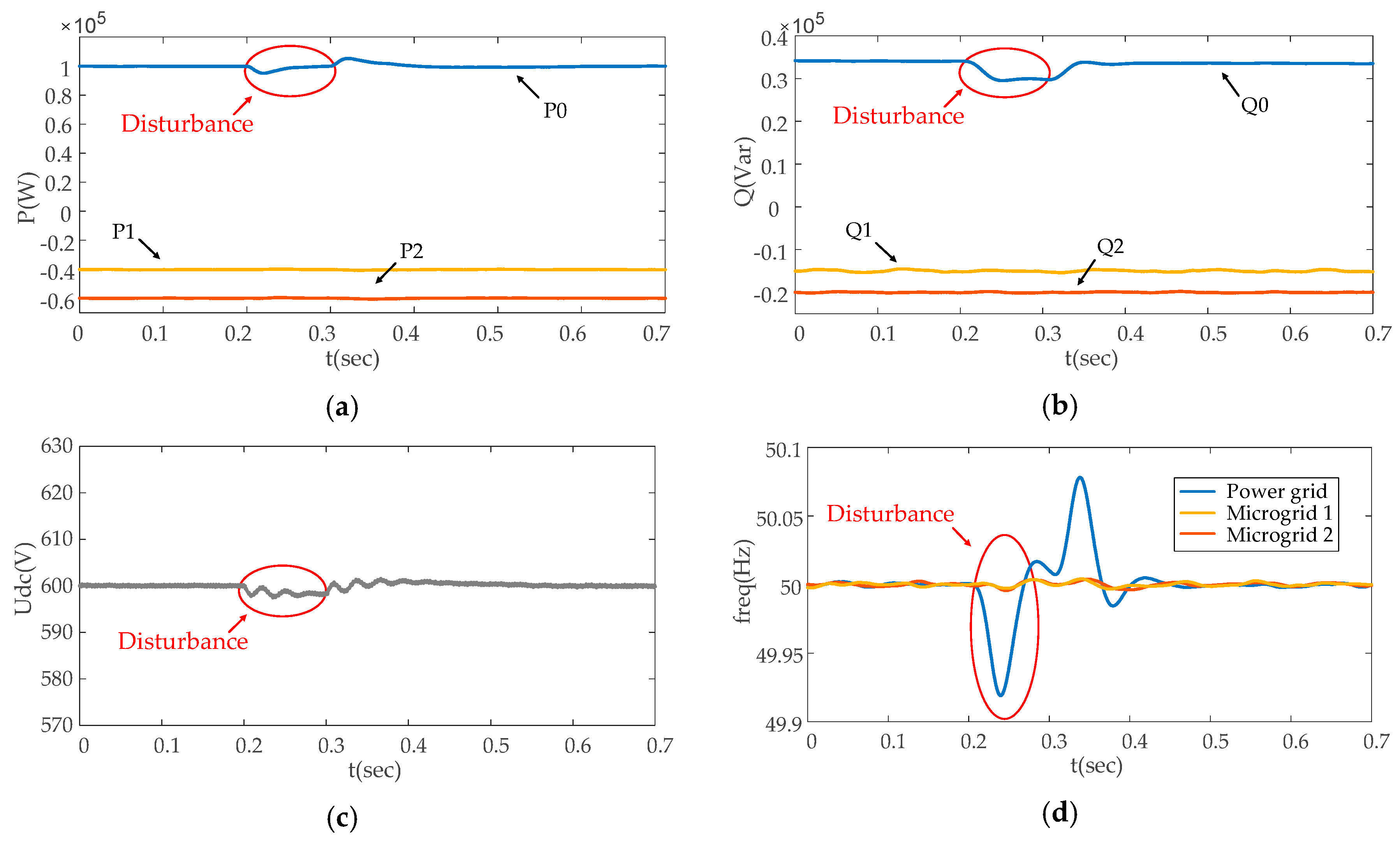
In this scenario, the characteristics of the microgrids are investigated when a disturbance occurs on the grid side. While the energy router is operating in the situation of case 1, it is assumed that voltage variation occurs on the power-grid side.
As shown in Figure 14, the disturbance on the grid side starts from t = 0.2 s and continues for the next 0.1 s. The amplitude of the grid voltage decreases by 5%, due to the disturbance. The variations in active/reactive power, DC-link voltage and AC frequency on the microgrid side during the process are shown in Figure 15.
When the disturbance occurs at t = 0.2 s, the power supplied from the power grid fluctuates within a narrow range. The DC-link voltage also fluctuates along with it, but recovers from the disturbance rapidly. More importantly, due to the electrical isolation functionalities of the energy router, the AC frequency and voltage on the microgrid side are not affected by the disturbance, as shown in Figure 15d.
7. Conclusions
This paper focused on a novel and flexible interconnecting framework for microgrids and corresponding energy management strategies, with the aim to maintain the energy balance and operational stability of the power system, and also alleviate the dependency on energy storage equipment. The presented framework enabled direct energy exchange between microgrids via the multiport energy router, based on the thought that adjacent microgrids may have complementarity in terms of the pattern of energy production and consumption, which can be utilized to compensate for each other’s instant energy deficiency. Facilitated by the energy router, the energy management patterns of the interconnected microgrids were expanded considerably. The operational modes were analyzed, and corresponding control strategies were developed for the energy router-based interconnected microgrids. Four scenarios were investigated based on the MATLAB R2014b/Simulink platform, whichdemonstrated that:
- (1)
- apart from the grid-connected mode and the islanded mode, microgrids interconnected with the energy router can operate in the parallel mode when flexible energy flow among adjacent microgrids is enabled by the energy router. Therefore, energy surpluses or deficits can be compensated by complementary energy exchanges on the microgrid side without interference of the main power grid;
- (2)
- facilitated by the energy router with the presented control strategies, the microgrids can switch freely and flexibly among the multiple operational modes, according to their energy demands and operational statuses;
- (3)
- The VSC converters and shared DC bus of the energy router facilitate electrical isolation between the microgrids and the main grid, which ensures that any voltage or frequency fluctuation at one end of the energy router will have no direct impact on the systems on other sides of the energy router, thus guaranteeing power quality and operational reliability.
Widespread implementations of the presented energy router-based interconnected microgrid scheme will promote the shift of the power system architecture from the traditional hierarchical framework to a more connective and interactive framework, which will be an essential step to build the Internet of Energy of the future.
Acknowledgments
This work is supported by the “Science and Technology Project Plan of the Ministry of Housing and Urban-Rural Development of the People’s Republic of China” (Project No.: 2016-K1-018).
Author Contributions
All the authors have contributed significantly. Yingshu Liu conceived and designed the model and corresponding control methods; Yue Fang performed the simulation; Yue Fang and Jun Li analyzed the results; Jun Li made all graphics; Yingshu Liu and Yue Fang wrote and revised the paper.
Conflicts of Interest
The authors declare no conflict of interest.
References
- Huang, A.Q.; Crow, M.L.; Heydt, G.T. The Future Renewable Electric Energy Delivery and Management (FREEDM) System: The energy internet. Proc. IEEE 2011, 99, 133–148. [Google Scholar] [CrossRef]
- Lasseter, R.H. Smart Distribution: Coupled Microgrids. Proc. IEEE 2011, 99, 1074–1082. [Google Scholar] [CrossRef]
- Walling, R.A.; Saint, R.; Dugan, R.C. Summary of Distributed Resources Impact on Power Delivery Systems. IEEE Trans. Power Deliv. 2008, 23, 1636–1644. [Google Scholar] [CrossRef]
- Barnes, M.; Kondoh, J.; Asano, H. Real-World MicroGrids-An Overview. In Proceedings of the 2007 IEEE International Conference on System of Systems Engineering, San Antonio, TX, USA, 16–18 April 2007; pp. 1–8. [Google Scholar]
- Olivares, D.E.; Mehrizi-Sani, A.; Etemadi, A.H. Trends in Microgrid Control. IEEE Trans. Smart Grid 2014, 5, 1905–1919. [Google Scholar] [CrossRef]
- Yang, Z.; Zhang, J.; Kintner-Meyer, M.C. Electrochemical Energy Storage for Green Grid. Chem. Rev. 2011, 111, 3577–3613. [Google Scholar] [CrossRef]
- Díaz, N.L.; Luna, A.C.; Vasquez, J.C. Centralized Control Architecture for Coordination of Distributed Renewable Generation and Energy Storage in Islanded AC Microgrids. IEEE Trans. Power Electron. 2017, 32, 5202–5213. [Google Scholar] [CrossRef]
- Bragard, M.; Soltau, N.; Thomas, S. The Balance of Renewable Sources and User Demands in Grids: Power Electronics for Modular Battery Energy Storage Systems. IEEE Trans. Power Electron. 2010, 25, 3049–3056. [Google Scholar] [CrossRef]
- Divya, K.C.; Østergaard, J. Battery Energy Storage Technology for Power Systems—An Overview. Electr. Power Syst. Res. 2009, 79, 511–520. [Google Scholar] [CrossRef]
- Cheng, S.; Sun, W.B.; Liu, W.L. Multi-Objective Configuration Optimization of a Hybrid Energy Storage System. Appl. Sci. 2017, 7, 163–174. [Google Scholar] [CrossRef]
- Levelized Cost of Storage Analysis 2.0. Available online: https://www.lazard.com/perspective/levelized-cost-of-storage-analysis-20/ (accessed on 15 December 2016).
- Lindley, D. The Energy Storage Problem. Nature 2010, 7, 18–20. [Google Scholar] [CrossRef]
- Clement-Nyns, K.; Haesen, E.; Driesen, J. The Impact of Vehicle-to-grid on the Distribution Grid. Power Syst. Res. 2011, 81, 185–192. [Google Scholar] [CrossRef]
- Baumann, C.; Schuster, R.; Moser, A. Economic Potential of Power-to-gas Energy Storages. In Proceedings of the International Conference on the European Energy Market(EEM), Stockholm, Sweden, 27–31 May 2013; pp. 1–6. [Google Scholar]
- Rodrigues, E.M.G.; Godina, R.; Santos, S.F. Energy Storage Systems Supporting Increased Penetration of Renewables in Islanded Systems. Energy 2014, 75, 265–280. [Google Scholar] [CrossRef]
- Díaz-González, F.; Sumper, A.; Gomis-Bellmunt, O. A Review of Energy Storage Technologies for Wind Power Applications. Renew. Sustain. Energy Rev. 2012, 16, 2154–2171. [Google Scholar] [CrossRef]
- Liu, Z.; Chen, C.; Yuan, J. Hybrid Energy Scheduling in a Renewable Micro Grid. Appl. Sci. 2015, 5, 516–531. [Google Scholar] [CrossRef]
- Huang, A.Q.; Baliga, J. FREEDM System: Role of Power Electronics and Power Semiconductors in Developing an Energy Internet. In Proceedings of the International Symposium on Power Semiconductor Devices and ICs, Barcelona, Spain, 14–18 June 2009; pp. 9–12. [Google Scholar]
- Zhang, J.; Wang, W.; Bhattacharya, S. Architecture of Solid State Transformer-based Energy Router and Models of Energy Traffic. In Proceedings of the 2012 Innovative Smart Grid Technologies (ISGT), Washington, DC, USA, 16–20 January 2012; pp. 1–8. [Google Scholar]
- Takahashi, R.; Kitamori, Y.; Hikihara, T. AC Power Local Network with Multiple Power Routers. Energies 2013, 6, 6293–6303. [Google Scholar] [CrossRef] [Green Version]
- Kandula, R.P.; Iyer, A.; Moghe, R. Power Router for Meshed Systems Based on a Fractionally Rated Back-to-Back Converter. IEEE Trans. Power Electron. 2014, 29, 5172–5180. [Google Scholar] [CrossRef]
- Xu, Y.; Zhang, J.; Wang, W. Energy Router: Architectures and Functionalities toward Energy Internet. In Proceedings of the 2011 IEEE International Conference on Smart Grid Communications (SmartGridComm 2011), Brussels, Belgium, 17–20 October 2011; pp. 31–36. [Google Scholar]
- Takuno, T.; Kitamori, Y.; Takahashi, R. AC Power Routing System in Home Based on Demand and Supply Utilizing Distributed Power Sources. Energies 2011, 4, 717–726. [Google Scholar] [CrossRef] [Green Version]
- Saponara, S.; Bacchillone, T. Network Architecture, Security Issues, and Hardware Implementation of a Home Area Network for Smart Grid. J. Comput. Netw. Commun. 2012, 7, 285–293. [Google Scholar] [CrossRef]
- Nguyen, P.H.; Kling, W.L.; Ribeiro, P.F. Smart power router: A flexible Agent-based Converter Interface in Active Distribution Networks. IEEE Trans. Smart Grid 2011, 2, 487–495. [Google Scholar] [CrossRef]
- Yu, X.; She, X.; Zhou, X. Power Management for DC Microgrid Enabled by Solid-state Transformer. IEEE Trans. Smart Grid 2014, 5, 954–965. [Google Scholar] [CrossRef]
- Zhang, Y.; Umuhoza, J.; Liu, Y. Optimized control of isolated residential power router for photovoltaic applications. In Proceedings of the Energy Conversion Congress and Exposition, Pittsburgh, PA, USA, 14–18 September 2014; pp. 53–59. [Google Scholar]
- Cao, J.W.; Meng, K.; Wang, J.Y. An energy internet and energy routers. Sci. Sin. Inf. 2014, 44, 714. [Google Scholar] [CrossRef]
- Saponara, S. Distributed Measuring System for Predictive Diagnosis of Uninterruptible Power Supplies in Safety-Critical Applications. Energies 2016, 9, 327. [Google Scholar] [CrossRef]
- Saponara, S.; Fanucci, L.; Bernardo, F. Predictive Diagnosis of High-Power Transformer Faults by Networking Vibration Measuring Nodes With Integrated Signal Processing. IEEE Trans. Instrum. Meas. 2016, 65, 1749–1760. [Google Scholar] [CrossRef]
- Tonkoski, R.; Turcotte, D.; El-Fouly, T.H.M. Impact of High PV Penetration on Voltage Profiles in Residential Neighborhoods. IEEE Trans. Sustain. Energy 2012, 3, 518–527. [Google Scholar] [CrossRef]
- Majumder, R.; Ghosh, A.; Ledwich, G. Power Management and Power Flow Control with Back-to-Back Converters in a Utility Connected Microgrid. IEEE Trans. Power Syst. 2010, 25, 821–834. [Google Scholar] [CrossRef] [Green Version]
Figure 1.
Energy router-based interconnecting framework for the microgrids system.
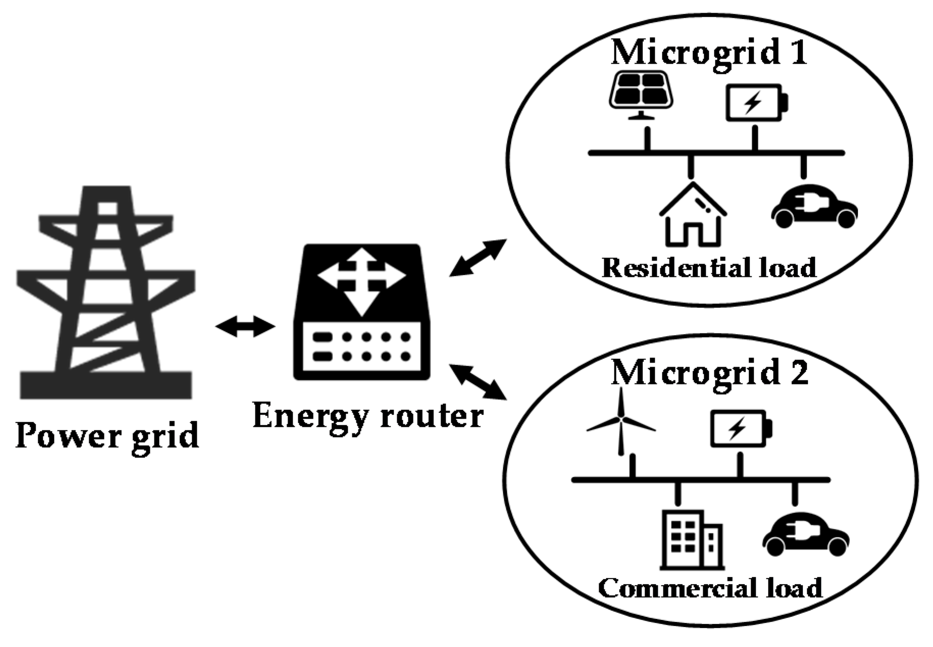
Figure 2.
Schematic block diagram of the energy router.
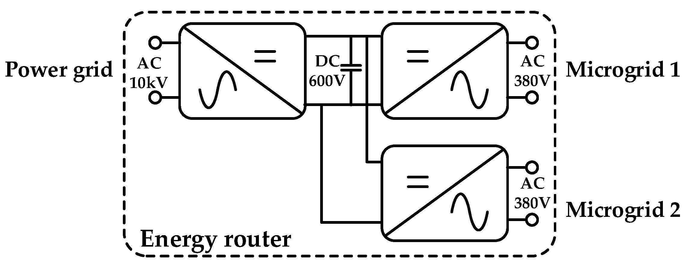
Figure 3.
Operational modes enabled by the energy router: (a) case 1: grid-connected mode; (b) case 2: grid connected mode vs. islanded mode; (c) case 3: grid connected mode vs. parallel mode; and (d) case 4: parallel mode.
Figure 3.
Operational modes enabled by the energy router: (a) case 1: grid-connected mode; (b) case 2: grid connected mode vs. islanded mode; (c) case 3: grid connected mode vs. parallel mode; and (d) case 4: parallel mode.
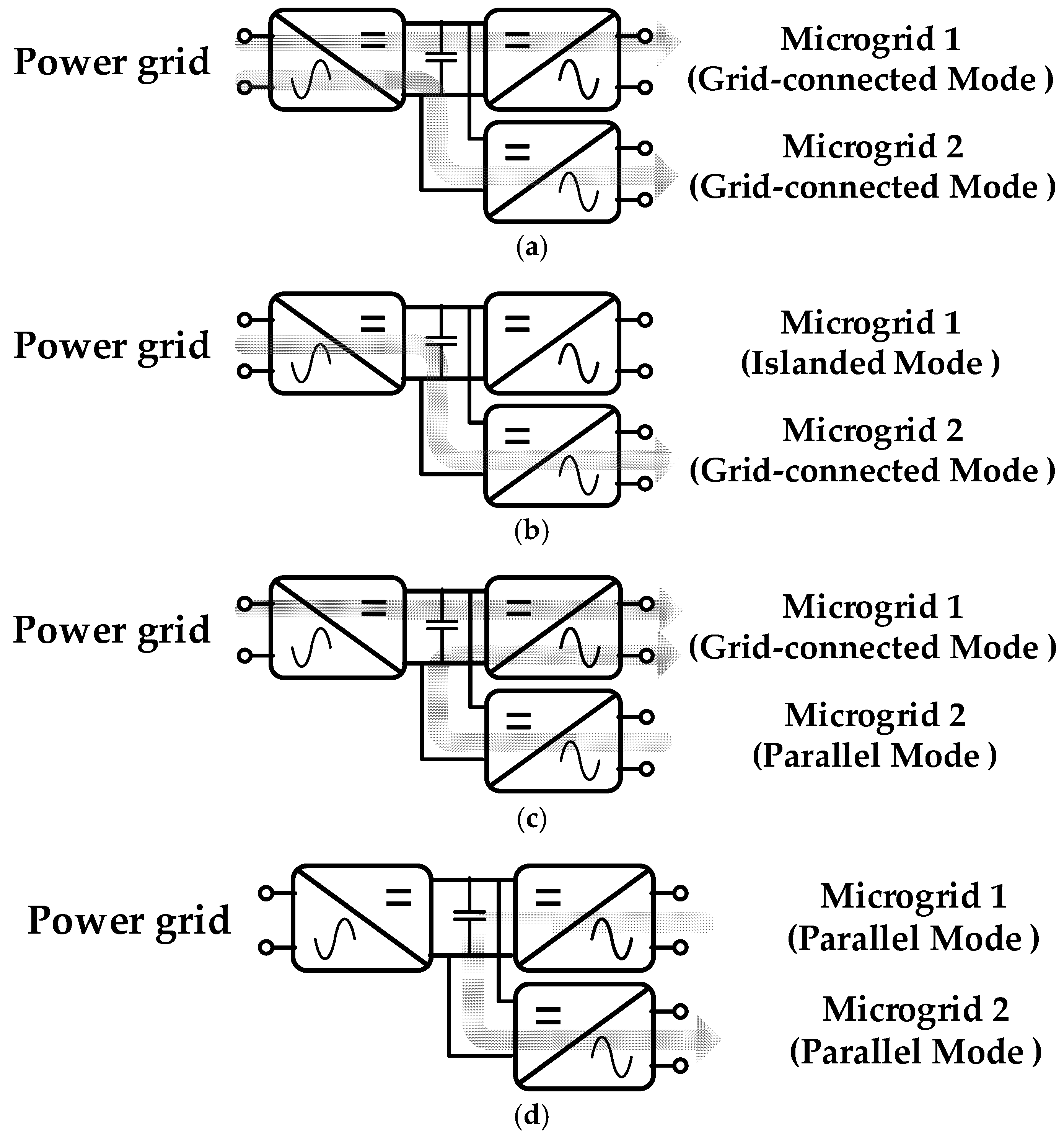
Figure 4.
The detailed topology of the energy router.
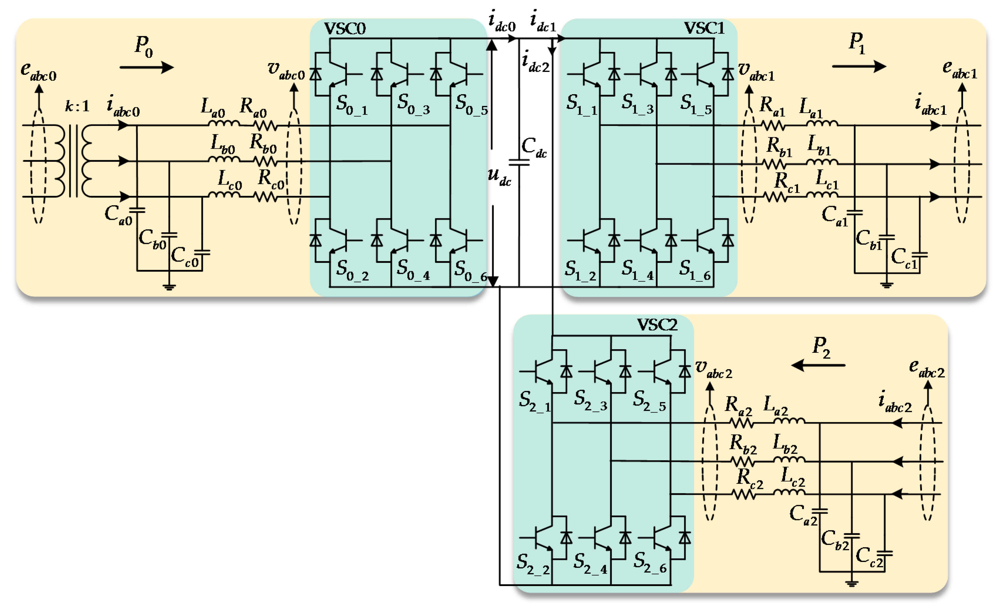
Figure 5.
Control schematic of the VSCs.
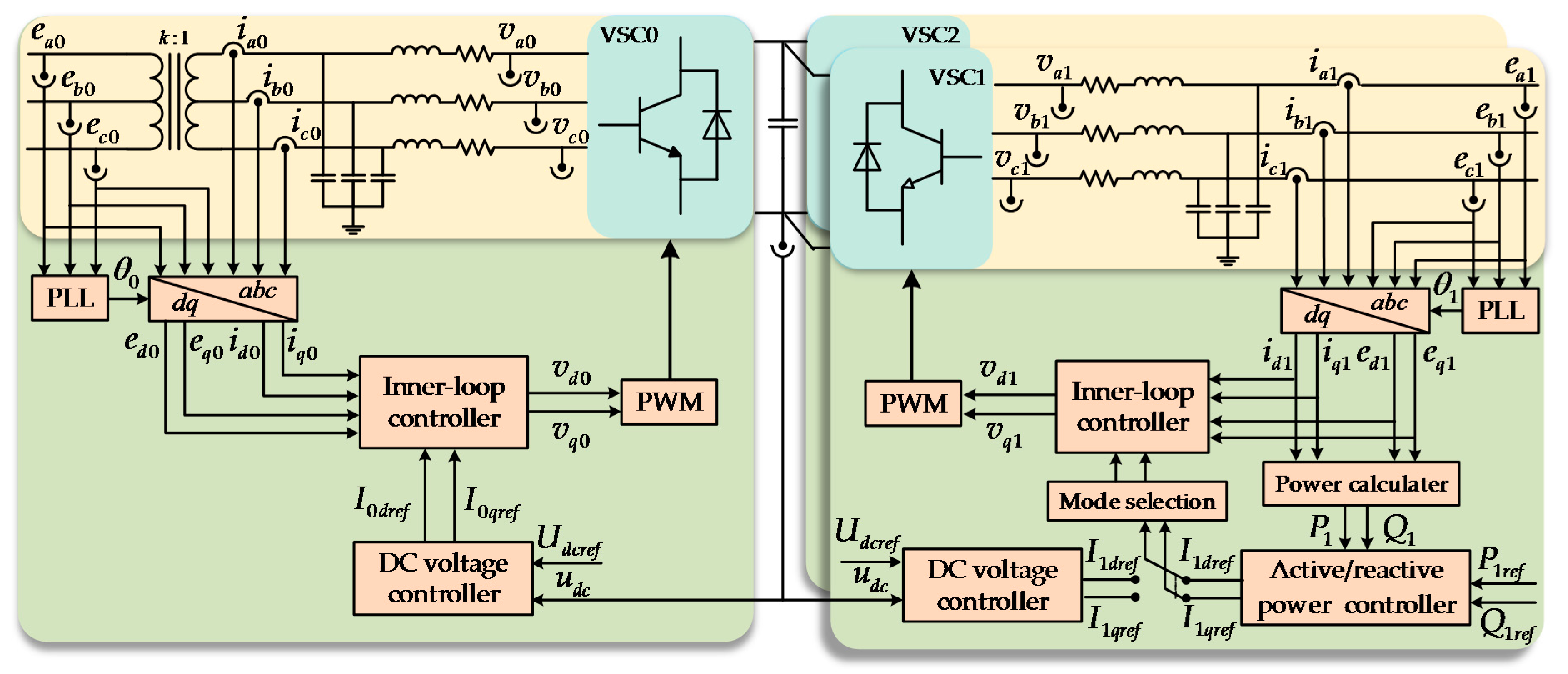
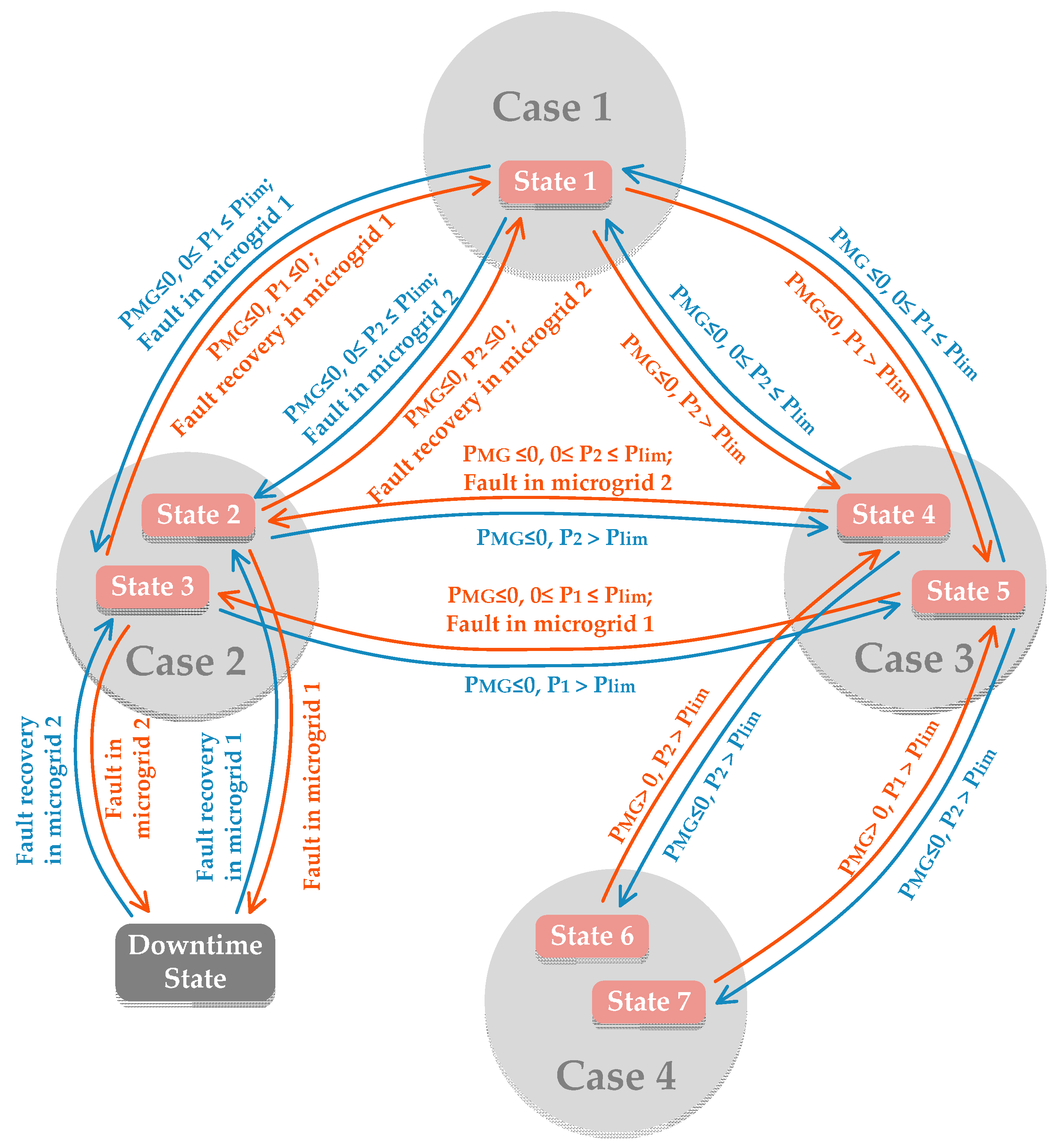
Figure 6.
State-transition diagram of the energy router.

Figure 7.
Control structure of the active power controller.
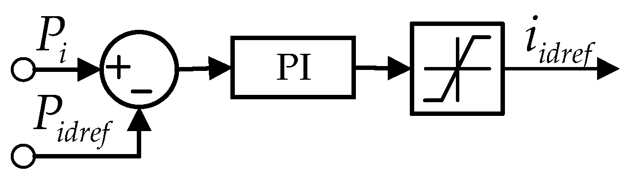
Figure 8.
Control structures of reactive power controller.

Figure 9.
Control structure of the DC voltage controller.
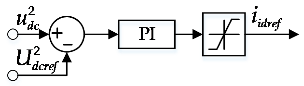
Figure 10.
Simulation model of the interconnected microgrid system in MATLAB R2014b/Simulink platform: (a) overall simulation model; (b) VSC0 simulation model; and (c) VSC controller simulation model.
Figure 10.
Simulation model of the interconnected microgrid system in MATLAB R2014b/Simulink platform: (a) overall simulation model; (b) VSC0 simulation model; and (c) VSC controller simulation model.

Figure 11.
Simulation results of scenario 1: (a) active power curves; (b) reactive power curves; (c) DC-link voltage curves; and (d) frequency curves.
Figure 11.
Simulation results of scenario 1: (a) active power curves; (b) reactive power curves; (c) DC-link voltage curves; and (d) frequency curves.

Figure 12.
Simulation results of scenario 2: (a) active power curves; (b) reactive power curves; (c) DC-link voltage curves; and (d) frequency curves.
Figure 12.
Simulation results of scenario 2: (a) active power curves; (b) reactive power curves; (c) DC-link voltage curves; and (d) frequency curves.

Figure 13.
Simulation results of scenario 3: (a) active power curves; (b) reactive power curves; (c) DC-link voltage curves; and (d) frequency curves.
Figure 13.
Simulation results of scenario 3: (a) active power curves; (b) reactive power curves; (c) DC-link voltage curves; and (d) frequency curves.
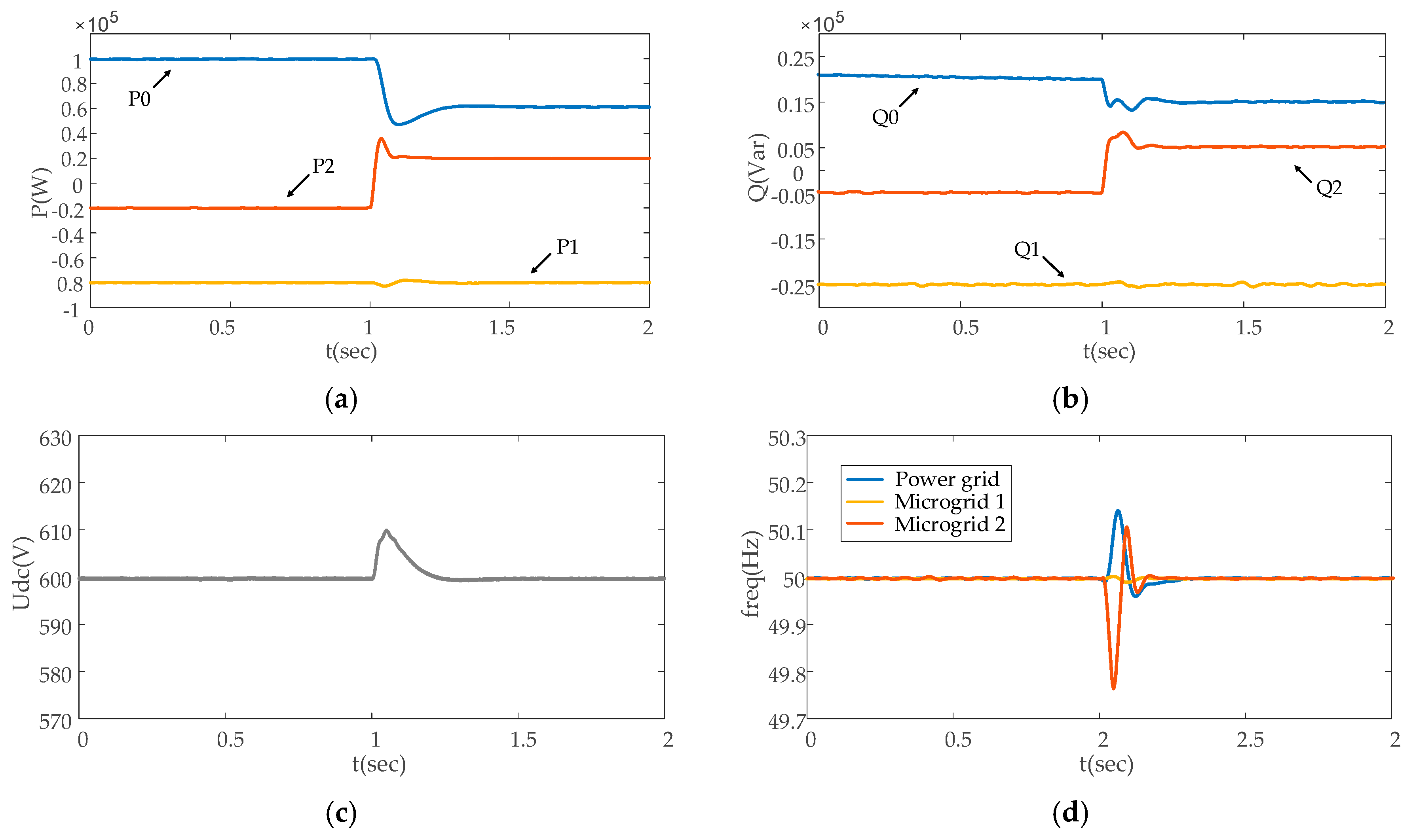
Figure 14.
Three-phase voltage curves on the grid side at the moment of disturbance.
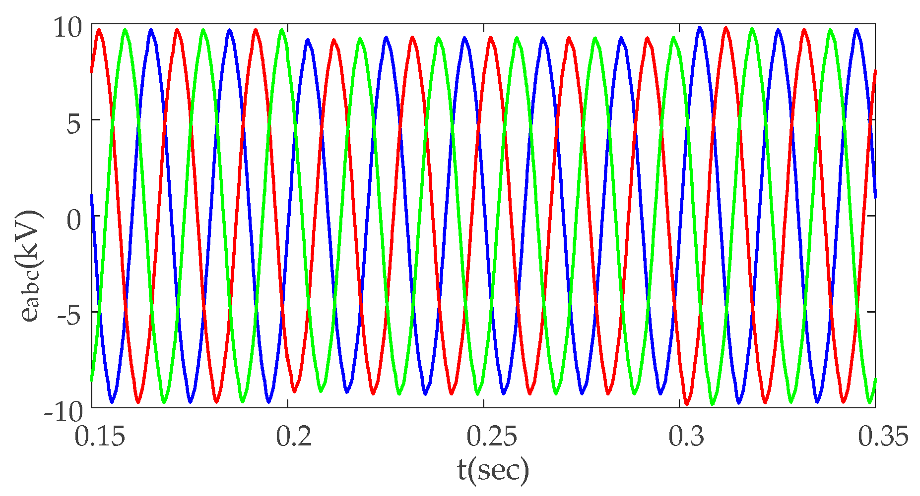
Figure 15.
Simulation results of scenario 4: (a) active power curves; (b) reactive power curves; (c) DC-link voltage curves; and (d) frequency curves.
Figure 15.
Simulation results of scenario 4: (a) active power curves; (b) reactive power curves; (c) DC-link voltage curves; and (d) frequency curves.

Table 1.
Definition of the control patterns for VSCs under different operational conditions.
| Control Pattern | Inner-Loop Controller | Outer-Loop Controller |
|---|---|---|
| Pattern 1 (master control) | Rectifier | DC voltage loop control |
| Pattern 2 | Rectifier | Active/reactive power control |
| Pattern 3 | Inverter | Active/reactive power control |
Table 2.
Operational modes of the microgrids vs. VSC control patterns in Figure 3a–d.
Table 2.
Operational modes of the microgrids vs. VSC control patterns in Figure 3a–d.
| Operational Cases | Operational Mode of Microgrid 1 | Operational Mode of Microgrid 2 | VSC0 | VSC1 | VSC2 |
|---|---|---|---|---|---|
| Case 1 (Figure 3a) | Grid-connected mode | Grid-connected mode | Pattern 1 | Pattern 3 | Pattern 3 |
| Case 2 (Figure 3b) | Islanded mode | Grid-connected mode | Pattern 1 | None | Pattern 3 |
| Case 3 (Figure 3c) | Grid-connected mode | Parallel mode | Pattern 1 | Pattern 3 | Pattern 2 |
| Case 4 (Figure 3d) | Parallel mode | Parallel mode | None | Pattern 1 | Pattern 3 |
Table 3.
All the states of the energy router.
| State | Operation Case | Power Grid | Microgrid 1 | Microgrid 2 |
|---|---|---|---|---|
| 1 | Case 1 | Include | Grid-connected mode | Grid-connected mode |
| 2 | Case 2 | Grid-connected mode | Island mode | |
| 3 | Island mode | Grid-connected mode | ||
| 4 | Case 3 | Grid-connected mode | Parallel mode | |
| 5 | Parallel mode | Grid-connected mode | ||
| 6 | Case 4 | Exclude | Parallel mode | Parallel mode |
| 7 | Parallel mode | Parallel mode | ||
| 8 | Downtime | Island mode | Island mode |
Table 4.
Simulation parameters.
| Parameters | Value |
|---|---|
| AC voltage of main grid | 10 kV |
| AC voltage of microgrid | 0.38 kV |
| DC-bus voltage | 600 V |
| DC-bus capacitance | 1 mF |
| Inductance of the filter | 0.25 mH |
| Capacitance of the filter | 250 μF |
| Switching frequency | 10 k Hz |
© 2017 by the authors. Licensee MDPI, Basel, Switzerland. This article is an open access article distributed under the terms and conditions of the Creative Commons Attribution (CC BY) license (http://creativecommons.org/licenses/by/4.0/).
Share and Cite
MDPI and ACS Style
Liu, Y.; Fang, Y.; Li, J. Interconnecting Microgrids via the Energy Router with Smart Energy Management. Energies 2017, 10, 1297. https://doi.org/10.3390/en10091297
AMA Style
Liu Y, Fang Y, Li J. Interconnecting Microgrids via the Energy Router with Smart Energy Management. Energies. 2017; 10(9):1297. https://doi.org/10.3390/en10091297
Chicago/Turabian StyleLiu, Yingshu, Yue Fang, and Jun Li. 2017. "Interconnecting Microgrids via the Energy Router with Smart Energy Management" Energies 10, no. 9: 1297. https://doi.org/10.3390/en10091297
Note that from the first issue of 2016, this journal uses article numbers instead of page numbers. See further details here.