New Prototype of Photovoltaic Solar Tracker Based on Arduino


1
Departamento de Tecnología de la Edificación, Universidad Politécnica de Madrid, 28040 Madrid, Spain
2
Departamento de Construcciones Arquitectónicas y su Control, Universidad Politécnica de Madrid, 28040 Madrid, Spain
3
Ciclo de Eficiencia Energética y Energía Solar Térmica, Institución Profesional Salesiana, Salesianos Carabanchel, 28044 Madrid, Spain
*
Author to whom correspondence should be addressed.
Energies 2017, 10(9), 1298; https://doi.org/10.3390/en10091298
Submission received: 28 July 2017
/
Revised: 19 August 2017
/
Accepted: 25 August 2017
/
Published: 30 August 2017
Abstract
:The global increase in energy demand and exponential exhaustion of fossil recourses has favored the development of new systems of electricity production. Photovoltaic solar energy is undoubtedly one that has the highest application in housings, due to its simplicity and easy implementation. In this work, a new prototype of photovoltaic solar tracker with Arduino platform was developed. Feedback control system that allows carrying out solar tracking with two axes using a stepper motor and linear actuator was established through an electronic circuit based on photodiodes. Moreover, real construction of the prototype was carried out, where the effectiveness of the design and its capacity to draw a maximum benefit of an incident radiation can be observed, placing the panel perpendicularly to the received energy and improving its performance for its application in future installations in housings. Results obtained from the comparison between the developed prototype and a static panel oriented according to the latitude of the area, show about 18% energy gain.
1. Introduction
Economic development of industrialized countries and exponential growth of population remarkably increased energy consumption in recent years [1]. This is why more and more regulations appear both at the national and international levels that strive to decrease energy consumption in order to avoid damaging and irreversible effects on the planet such as exhaustion of fossil fuel and global warming [2,3]. One of the sectors that was the most affected in the last years by the arrival of these new legislations is the building sector that is increasingly using renewable energy sources for the production of heating and electricity [4]. Solar energy is an undoubtedly inexhaustible source of energy that is most commonly used nowadays due to its abundance and its scarce pollutant emissions generated during its production [5].
Photovoltaic solar energy is the most commonly used in housings due to its simple installation and good quality-to-price ratio compared to other technological applications (parabolic cylinder collectors, Stirling dish parabolic collectors, etc.), that even though reach higher levels of electric energy production, present practically insurmountable difficulties for its architectural integration [6,7]. There is a great amount of research that tries to improve the performance of this type of installations using double-sided panels [8], concentration lenses [9], geometrically integrated into buildings panels [10], development of new solar cells [11], improvement in stages of conversion [12], etc.
In order to obtain maximum output power of a photovoltaic module or a set of modules, it is necessary to have an automated system able to orient the surface of the panel in a way that the highest possible amount of solar radiation reaches its surface perpendicularly to generate the highest peaks of energy production. For that purpose, numerous authors developed diverse prototypes of solar photovoltaic trackers in order to improve the performance of this technology [13,14]. In general, all of them have a fixed part of structure and moving part composed of tracking equipment and energy production equipment [15].
Out of all solar trackers existing in the market, the most effective are those that move in two axes, azimuthal and zenithal [16,17]. Compared to a properly inclined fixed solar panel, energy gain can be considerably increased using this type of solar tracking systems. These systems of tracking with two axes have been developed using two types of the most commonly used automatic control systems, with open loop and closed loop [18,19]. Tracking in closed loop is more effective as it uses various active sensors responsible for receiving signals of solar radiation, such as light-dependent resistance (LDR) or charge-coupled device (CCD), and moreover, it has a feedback to the controller that allows constantly orienting the panel making the most of its effectiveness [20,21]. At the moment, when an error signal previously calibrated coming from the control system is produced, the motors are activated and the surface of the panel is redirected [22,23].
On the other hand, in the market there is a great variety of controllers capable to interpret the signal of automated regulation systems. Referring to the solar tracking equipment, generally complex strategies of tracking with chips of microprocessors as control platforms are used [24]. Arduino platform that functions using free software has experienced a considerable rise since it appeared over a decade ago. For this reason, more and more researchers use this technology to program their equipment [25,26]. In the field of solar energy, Arduino sensors are also used to improve the performance of this type of installations through the implementation of solar trackers. They are also used to measure one of the most common parameters in these systems of energy production, giving really satisfying results and considerable economic saving compared to other commercial controllers [27,28,29,30].
This paper proposes a new prototype of photovoltaic solar tracker with two axes based on Arduino technology. A block of four high-sensitivity photodiodes able to emit an electric response that is interpreted by the Arduino UNO controller was used to capture radiation levels. A stepper motor was used to provide azimuthal movement and a linear actuator was used to obtain an optimal inclination. This system is completely autonomous and can improve the levels of energy production of photovoltaic solar panels. In order to calculate energy gain obtained using developed solar tracker, the levels of energy produced by the prototype and by a static panel oriented according to the latitude of the area were compared. Developed prototype is competitive for its installation on a flat roof and other exterior horizontal building elements to improve the performance of photovoltaic installations at a reduced cost.
2. Methodology
This section describes the design and fabrication of the prototype of photovoltaic solar tracker.
2.1. 3D Prototype Design
To carry out 3D design of solar tracker drawing tool FreeCAD 0.15 (London, UK) [31] was used. This tool allows to represent all the elements of the prototype and to visualize its final result before the fabrication, being compatible with other formats of graphic design. Figure 1 shows the design of the solar tracker.
Table 1 shows the description of the components of the prototype classified according to their functions.
2.2. Simulation of the Prototype
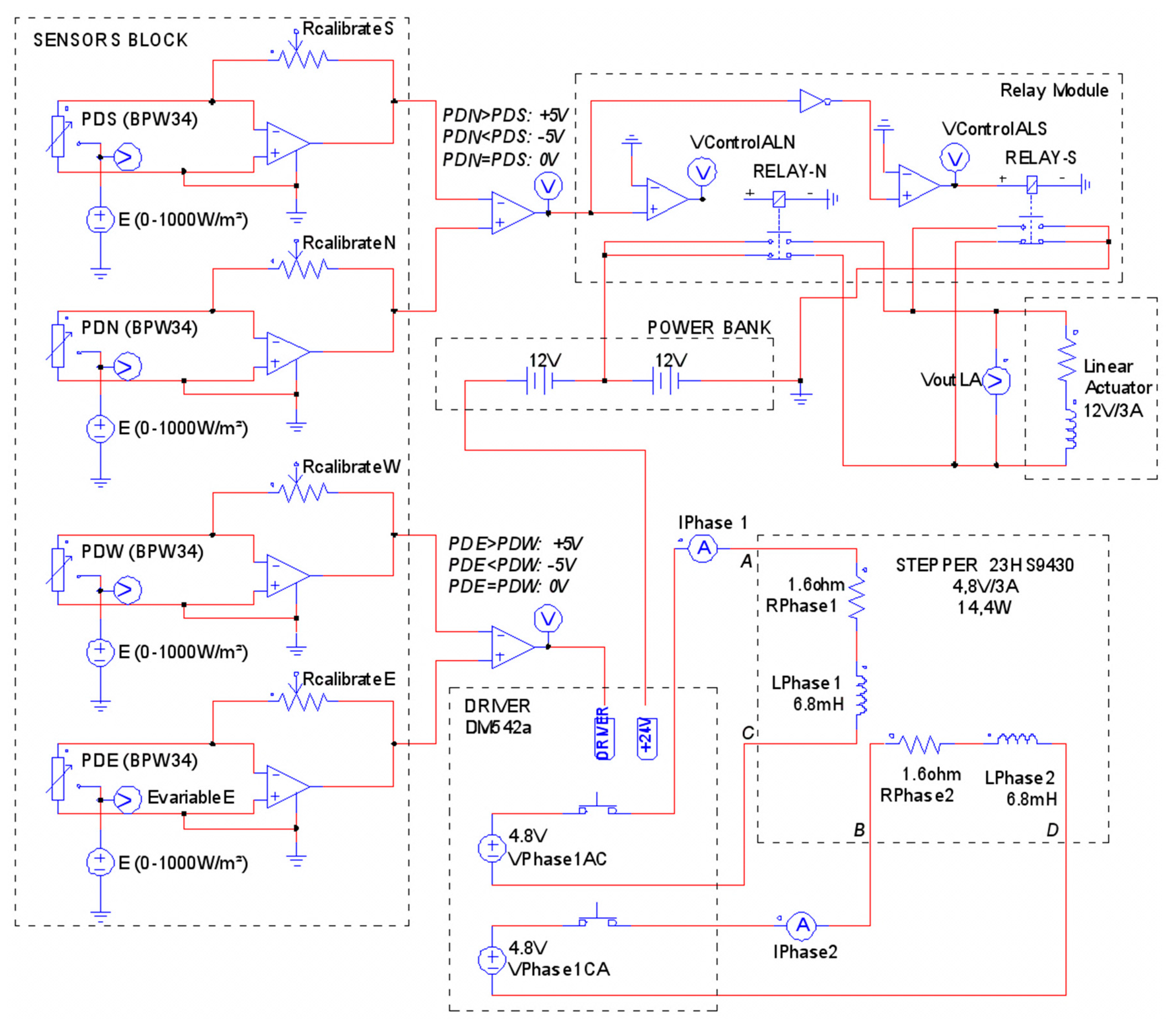
Before the construction of the prototype, a model was developed to validate the performance of the equipment with regard to the variations of an incident solar radiation on the photodiodes (North = PDN, South = PDS, East = PDE, West = PDW), validating the proposed scheme and the response of the block of sensors towards the variations of radiation in both movements, azimuthal (checking the response of stepper motor) and zenithal (checking the response of linear actuator). The model was implemented through the electric scheme of the tracker at functional level using PSIM© software (version 10.0.4, Powersim Inc., Rockville, MD, USA) [32]. Electric scheme of the simulation can be observed in Figure 2.
As it can be seen in Figure 2, the photodiodes were modeled with the help of nonlinear resistance that gives intensity response according to the voltage and incident radiation. Relay module that controls the functioning of linear actuator was built with the help of two contacts (NO and NC) in a way that if the incident radiation in North photodiode exceeds the radiation in South photodiode, North relay activates with +12 V voltage in terminals of linear actuator, acting towards elongation; otherwise South relay activates moving back the rod of the motor. NEMA 23HS9430 stepper was modeled according to the parameters that define two phases of the motor, an inductance per phase of 6 Ω and 6.8 mH respectively. The activation of each step of the motor and the direction of rotation require logic of control that assumes the driver DM542a that is also responsible for providing sufficient power for the requirements of the motor through the batteries. This stepper is responsible for azimuthal movement after having been compared to the levels of radiation in the photodiodes West and East.
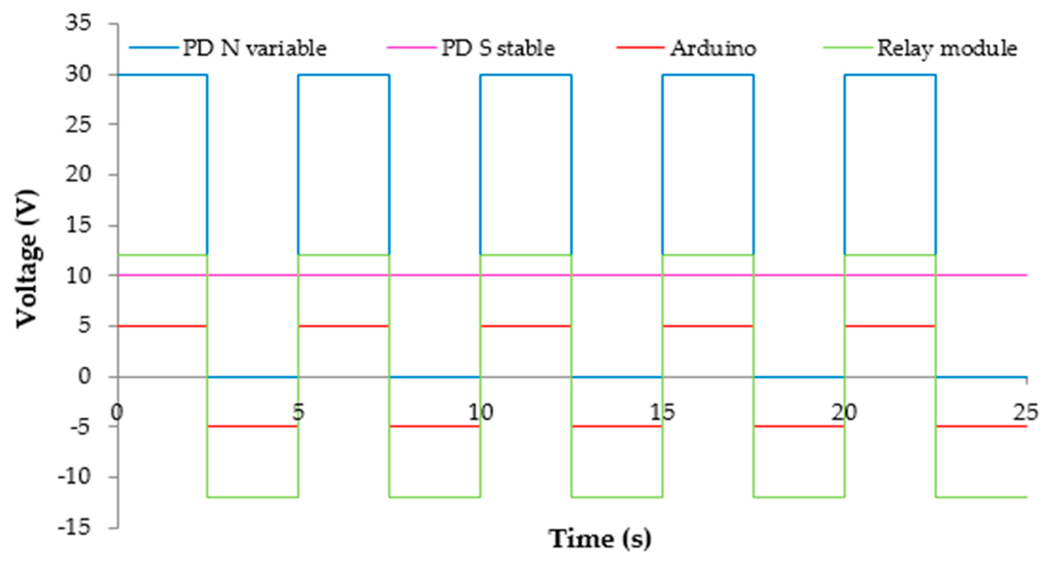
The results of the simulation are shown in Figure 3 and Figure 4. In case of Figure 3, South radiation is fixed in 10 W/m2 and solar radiation varies towards North direction between 0 and 30 W/m2, which are small values to be able to check in the same graphic the functionality of comparison stages at the beginning of the linear actuator functioning (voltages of ±5 V in Arduino controller and ±12 V in linear actuator). It can be observed that when North radiation exceeds South one, output voltage of Arduino is +5 V activating the rod of linear actuator that is placed at +12 V, and conversely when South radiation exceeds North one. In case of stepper motor shown in Figure 4, the logic is the same, keeping in this case East radiation fixed and West radiation variable. In this case stepper motor always consumes 3 A in each movement. For both movements the time of 25 s was established for the simulation, with a radiation variation frequency between the photodiodes of 0.2 Hz, being this a repetition of one complete wave every 5 s.
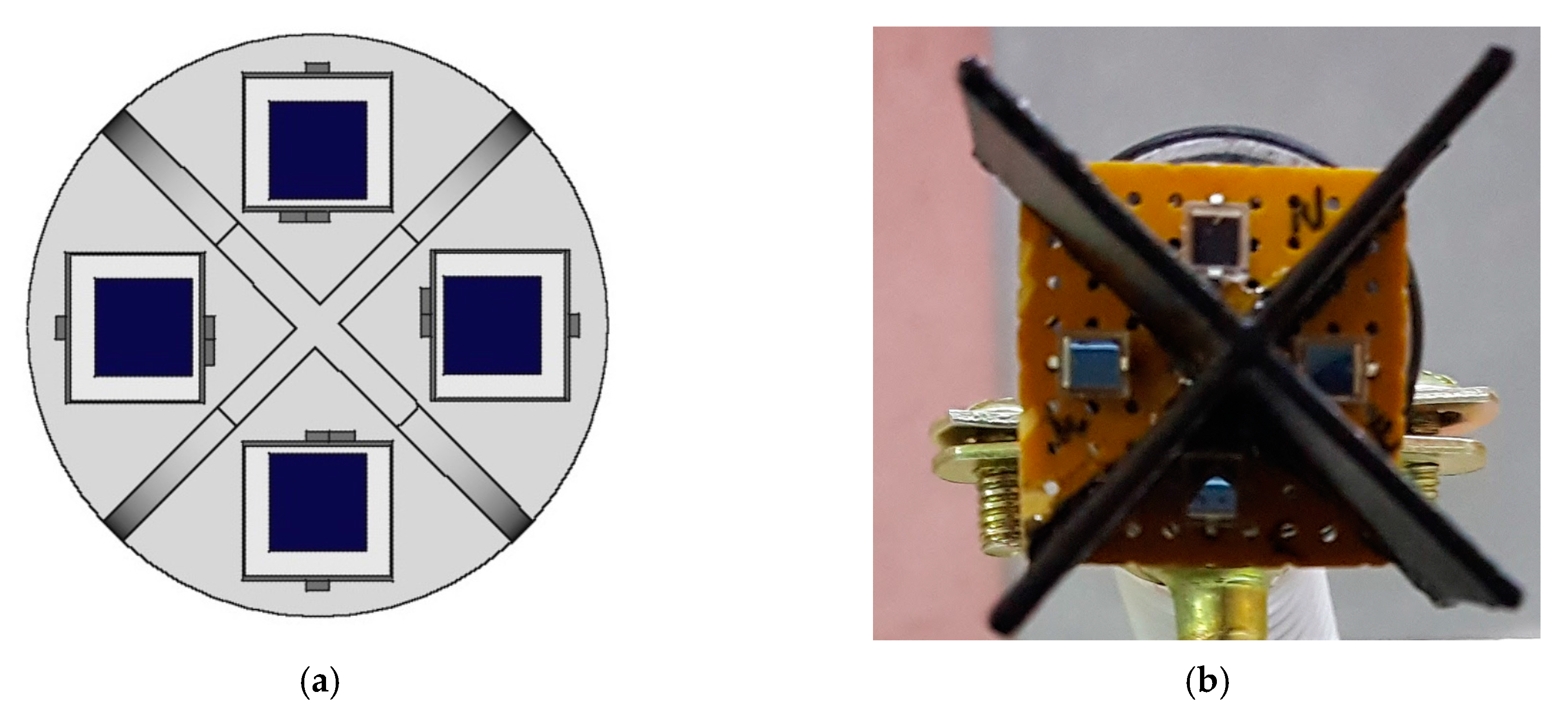
To obtain these appreciable variations of radiation, a block of sensors with four photodiodes was designed in a way that with the help of a structure in form of a cross the levels of radiation are more sensitive to the variations of the position of the sun thanks to its own shade. Additionally, this block of photodiodes is situated on the same plan as a photovoltaic panel, as shown in Figure 5.
As it can be seen in the final state in Figure 5b, the cross to differentiate cardinal points was custom made with the help of a 3D printer with polyethylene of dark color.
2.3. Solar Tracker Algorithm Definition
The descriptive diagram of blocks of solar tracker in closed developed loop is shown in Figure 6. Its objective is to obtain the maximum perpendicularity between the incident rays of sun and the surface of photovoltaic panel. Feedback controller is based on the Arduino platform and the block of sensors is based on the photodiodes and operation amplifier of type 741. The input to the comparator is the intensity of output received from the block of photodiodes, which is amplified and generates error voltage of feedback, being the variance between the responses of the sensors North-South and West-East the cause of this imbalance. At this moment the comparator sensitive to these variations of radiation two by two activates a linear actuator being the rod extended or moved back to obtain the maximum performance in elevation movement, or activates the driver that allows turning by means of stepper motor improving the effectiveness in azimuthal movement. Consequently, the controller maintains the photovoltaic panel and solar radiation monitored, sending a differential signal when the difference occurs what allows positioning the solar panel until practically zero error voltage is obtained. Each pair of data (azimuth and elevation) is captured and stored by the Arduino platform regularly, and after being interpreted, it activates the movement of motors.
Under the premises of the diagram of blocks the control algorithm was designed as flow diagram that allows checking all the photodiodes positioning the prototype. This diagram can be seen in Figure 7.
Therefore, according to the flow diagram shown in Figure 7, the variable that predominates over the movement of the tracker is the radiation, that is different to zero during daylight hours and equal to zero from the nightfall until the beginning of a new day. The tracker stays positioned towards West once the day is over and before starting a new day of measuring. Moreover, with an aim to avoid possible components wear caused by mechanical vibrations produced by continuous starts and stops of motors, the measurements were spaced every 10 min, reducing in this way the frequency of capture and possible saturation of the system.
3. Results and Discussion
Once the work of design and simulation of the prototype was done, real fabrication began. Design guidelines indicated in the previous section were followed and a scheme of real wiring of the prototype with the sensors block and two motors was carried out, according to the simulation done by PSIM©. This scheme of wiring that can be seen in Figure 8 was implemented inside a custom printed box made from polyethylene complying with the requirements of ventilation for the circuitry and avoiding possible overheating [33].
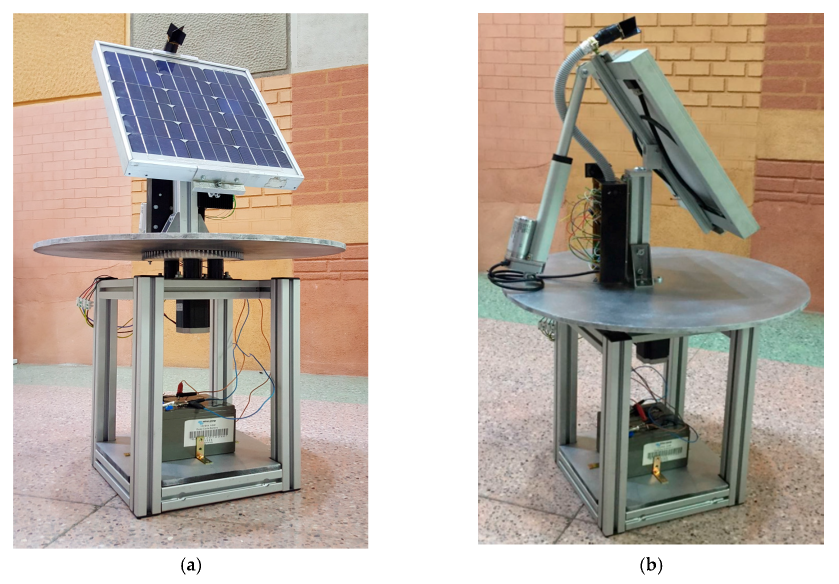
As can be observed in Figure 9, the built prototype can be controlled through laboratory test or even through dynamic simulators that model the parameters of irradiance and energy production.
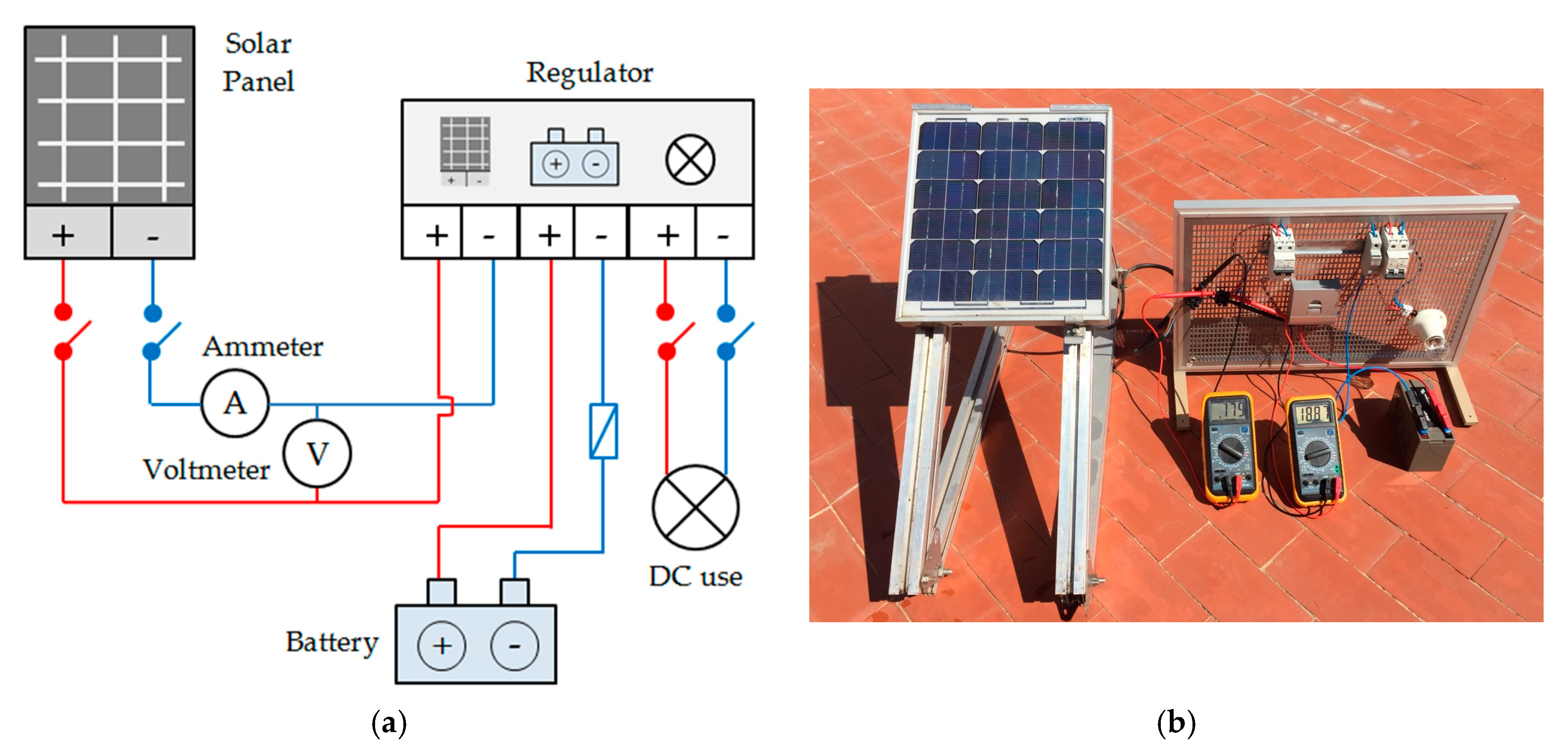
Moreover, as shown in Figure 10, a solar photovoltaic installation was performed, using the same typology of photovoltaic panel as in developed solar tracker prototype with 30° inclination and south orientation. In this way, the comparison between both systems was carried out, calculating the difference in energy production.
Obtained Production and Collected with the Tracker Data
First, Figure 11 presents results obtained in the production of the prototype and static panel during the months from January until May. For this, the prototype was placed on the roof of the center Salesianos Carabanchel in Madrid (Latitude 40.37° and Longitude −3.75°), capturing data every 30 min, and obtaining the average daily production achieved by the panel performing the tracking.
As it can be observed, the levels of energy production keep a direct relation with the environment conditions registered in the area at the moment of data collection, as shown in Figure 11. Clear days and those of higher temperatures are ones that give the highest levels of energy production. Moreover, as it can be observed in Figure 11, solar tracker prototype allows for obtaining higher energy production compared to static panel. This gain in production was about 18%, being in accordance with the average values obtained by other authors using different technologies of solar tracking [34,35]. Consequently, used low cost technology with Arduino can be validated as a tool for solar trackers design.
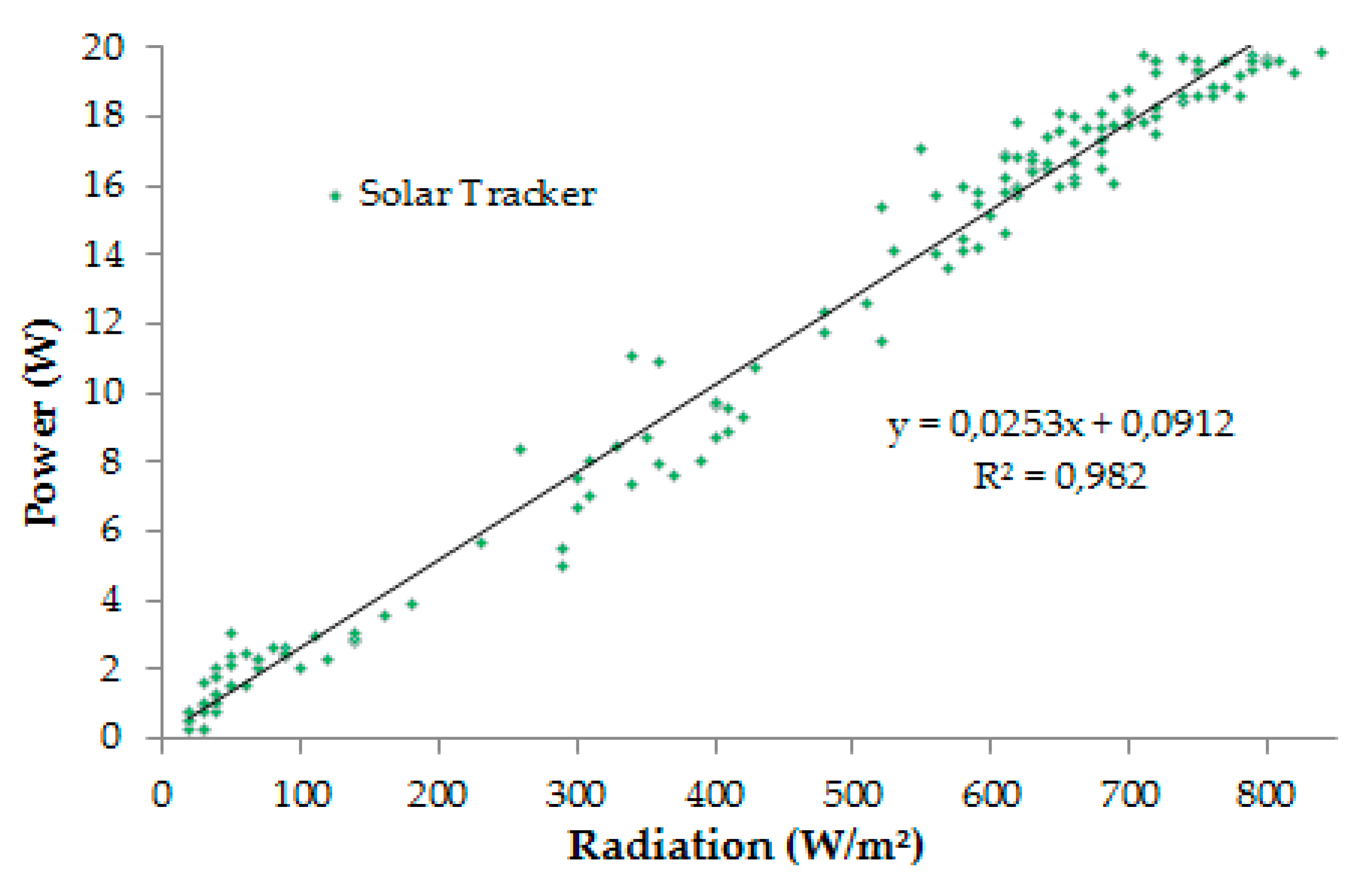
Furthermore, existing correlation between the average produced power and average incident radiation over the surface of the tracking panel can be seen in Figure 12.
Therefore, Figure 12 shows a linear relation among the levels of production and average incident irradiance, what is really useful for further theoretical calculations that allow measuring the maximum performance that can be reached by the panels placed in a determined geographic situation knowing only the levels of radiation in the area. To implement these systems in building of houses, the consumption of motors has to be deducted from the obtained energy production that in clear areas is in any case lower than reached production. On the other hand, varying the calibration of the sensors and adjusting the frequency of tracking to the real conditions of the geographic location, the electric production can improve even more.
In relation to the analysis of the prototype fabrication cost, consulting known commercial sources [36,37,38], not superior to 800 euros cost was obtained. In terms of large-scale production, such as solar farms, developed solar tracker is not competitive with commercial systems that are able to move hundreds of photovoltaic panels. However, it can be competitive for small less powerful installations placed on flat surfaces. Lightweight of this type of prototype is one of its advantages for installation in houses, where it is not feasible to place large masses that can generate loads on the building structure, or vibrations caused by rotating movements that could coincide with fundamental resonance frequencies of the building structure. Moreover, the fact of using Arduino as electronic control card, provides it with a power comparable to any commercial PLC, but at lower cost, not only because of the device itself, but also because of great amount of developed freeware programs that allow modelling, programming and simulating of previous behavior of these systems. That is why this type of prototype is ideal for its installation in houses without presenting any serious technical difficulties and at a reduced cost.
4. Conclusions
This paper offers a new and effective prototype of photovoltaic solar tracker based on Arduino platform that with a reduced cost and following logic of effective control is able to move autonomously and regularly under different conditions of irradiance. Moreover, a previous simulation of tracker’s behavior was achieved, which is able to anticipate the movement of the prototype in phase of design, what is really useful to know is the suitability of the device.
On the other hand, the effectiveness of the tracker was verified taking measurements during five months, observing a good correlation between the maximum levels of daily radiation in the area and the levels of energy production reached by the prototype. Furthermore, results obtained from the comparison between the reference static solar installation and developed solar tracker prototype show 18% energy gain using this latter, applying the same type of photovoltaic panel in both cases. These results show the effectiveness of the device, and suggest its possible use in buildings (flat roofs, garden areas, plots, etc.) or centers of photovoltaic production using scale models and developing a correct encapsulation for electric and electronic components what would allow the equipment to endure adverse weather conditions. Finally, and thanks to the versatility of Arduino platform, it would be possible to integrate a unit of control of environmental parameters that would complete commercially the design of the solar tracker developed in this work.
Finally, despite the fact that the prototype presents a lower performance compared to other commercial equipment (approximately 12% lower), it is competitive for its installation in houses, due to its low fabrication cost, easiness to be integrated in the building and simplicity to be programmed and to update tracking software as it belongs to Arduino community.
Acknowledgments
The authors would like to express their gratitude to Vicente Martínez and José Daniel Sanz for collaboration in prior calibration of photodiodes and to José Luis Rodríguez for collaboration in machining of prototype’s components; both are professors of Professional Institution Salesiana Carabanchel with wide experience.
Author Contributions
All the authors have designed the experiment and worked in the development of the prototype equally throughout the project. Carlos Morón and Daniel Ferrández created and designed the experiments. Gabriela Vega and Daniel Ferrández performed the experiments; Carlos Morón and Pablo Saiz analyzed the data; Daniel Ferrández wrote the article. Jorge Pablo Díaz helped to analyze the documents.
Conflicts of Interest
The authors declare no conflict of interest.
References
- Walsh, A.; Cóstola, D.; Chebel, L. Review of methods for climatic zoning for building energy efficiency programs. Build. Environ. 2017, 112, 337–350. [Google Scholar] [CrossRef]
- Fontanet, L.; García, J. Gestión del medioambiente urbano. Residuos que se generan en la actividad de la construcción. Directiva U.E. “Demotion Waste”. Inf. Constr. 1996, 47, 137–144. [Google Scholar] [CrossRef]
- Ministerio de Fomento. Real Decreto 314/2006 por el que se Aprueba el Código Técnico de la Edificación; Boletín Oficial del Estado (BOE): Madrid, Spain, 2006; pp. 11816–11831.
- Gustafsson, M.; Dipasquale, C.; Poppi, S.; Bellini, A.; Fedrizzi, R.; Bales, C.; Ochs, F.; Sié, M.; Holmberg, S. Economic and environmental analysis of energy renovation packages for European office buildings. Energy Build. 2017, 148, 155–165. [Google Scholar] [CrossRef]
- Gonçalves, P.; Orestes, M. Photovoltaic solar energy: Conceptual framework. Renew. Sustain. Energy 2017, 74, 590–601. [Google Scholar] [CrossRef]
- Martín, N.; Montero, D. Optimizing photovoltaic self-consumption in office. Energy Build. 2017, 150, 71–80. [Google Scholar] [CrossRef]
- Kim, B.; Kim, K.; Kim, K. Determining the optimal installation timing of building integrated photovoltaic systems. J. Clean. Prod. 2017, 140, 1322–1329. [Google Scholar] [CrossRef]
- Lo, C.K.; Lim, Y.S.; Rahman, F.A. New integrated simulation tool for the optimum design of bifacial panel with reflectors panels on a specific site. Renew. Energy 2015, 81, 293–307. [Google Scholar] [CrossRef]
- Beltagy, H.; Semmar, D.; Lehaut, C.; Said, N. Theoretical and experimental performance analysis of a Fresnel type solar concentrator. Renew. Energy 2017, 101, 782–793. [Google Scholar] [CrossRef]
- Spertino, F.; Ahmad, J.; Ciocia, A.; Di Leo, P. Techniques and experimental results for performance analysis of photovoltaic modules installed in buildings. Energy Procedia 2017, 111, 944–953. [Google Scholar] [CrossRef]
- Zhang, Y.; Kappers, M.J.; Zhu, D.; Oehler, F.; Gao, F.; Humphreys, C.J. The effect of dislocations on the efficiency of InGaN/GaN solar cells. Sol. Energy Mater. Sol. Cells 2013, 117, 279–284. [Google Scholar] [CrossRef]
- Van der Meer, D.W.; Widen, J.; Munkhammar, J. Review on probabilistic forecasting of photovoltaic power production and electricity consumption. Renew. Sustain. Energy Rev. 2017. [Google Scholar] [CrossRef]
- Quesada, G.; Guillon, L.; Rousse, D.; Mehrtash, M.; Dutil, Y.; Paradis, P.L. Tracking strategy for photovoltaic solar systems in high latitudes. Energy Convers. Manag. 2015, 103, 147–156. [Google Scholar] [CrossRef]
- Miloudi, L.; Acheli, D.; Ahmed, C. Solar tracking with photovoltaic system. Energy Procedia 2013, 42, 103–112. [Google Scholar] [CrossRef]
- Wang, J.; Lu, C. Design and Implementation of a Sun Tracker with a Dual-Axis Single Motor for an Optical Sensor-Based Photovoltaic System. Sensors 2013, 13, 3157–3168. [Google Scholar] [CrossRef] [PubMed]
- Hong, T.; Jeong, K.; Ban, C.; Oh, J.; Koo, C.; Kim, J.; Lee, M. A preliminary study on the two-axis hybrid solar tracking method for the smart photovoltaic blind. Energy Procedia 2016, 88, 484–490. [Google Scholar] [CrossRef]
- Fathabadi, H. Novel high efficient offline sensorless dual-axis solar tracker for using in photovoltaic systems and solar concentrators. Renew. Energy 2016, 95, 485–494. [Google Scholar] [CrossRef]
- Mi, Z.; Chen, J.; Chen, N.; Bai, Y.; Liu, H. Open-loop solar tracking strategy for high concentrating photovoltaic systems using variable tracking frequency. Energy Convers. Manag. 2016, 117, 142–149. [Google Scholar] [CrossRef]
- Garrido, R.; Díaz, A. Cascade close-loop control of solar trackers applied to HCPV systems. Renew. Energy 2016, 97, 689–696. [Google Scholar] [CrossRef]
- Fernández, L.M.; Casares, F.J.; Ramírez, J.; López, R. Mathematical study of the movement of solar tracking systems based on rational models. Sol. Energy 2017, 150, 20–29. [Google Scholar] [CrossRef]
- Fathabadi, H. Comparative study between two novel sensorless and sensor based dual-axis solar trackers. Sol. Energy 2016, 138, 67–76. [Google Scholar] [CrossRef]
- Mousazadeh, H.; Keyhani, A.; Javadi, A.; Mobbli, H.; Abrinia, K.; Sharifi, A. A review of principle and sun-tracking methods for maximizing solar systems output. Renew. Sustain. Energy 2009, 13, 1800–1818. [Google Scholar] [CrossRef]
- Ribeiro, S.C.; do Prado, P.P.L.; Gonçalves, J.B.; de Souza Soares, Á.M. Design and development of a low-cost solar tracker. Aust. J. Mech. Eng. 2013, 11, 139–150. [Google Scholar] [CrossRef]
- Sidek, M.H.M.; Azis, N.; Hasan, W.Z.W.; Ab Kadir, M.Z.A.; Shafie, S.; Radzi, M.A.M. Automated positioning dual-axis solar tracking system with precision elevation and azimuth angle control. Energy 2017, 124, 160–177. [Google Scholar] [CrossRef]
- Gad, H.E.; Gad Hisam, E. Development of a new temperature data acquisition system for solar energy applications. Renew. Energy 2015, 74, 337–343. [Google Scholar] [CrossRef]
- Garcia-Fuentevilla, L.; Payan-de-Tejada-Alonso, A.; Moron-Fernandez, C. Temperature and relative humidity monitoring system in buildings. A study case of a flat in Madrid. DYNA 2017, 92, 226–229. [Google Scholar]
- Morón, C.; Diáz, J.P.; Ferrández, D.; Ramos, M.P. Mechatronic Prototype of Parabolic Solar Tracker. Sensors 2016, 16, 882. [Google Scholar] [CrossRef] [PubMed]
- Bawa, D.; Patil, C.Y. Fuzzy control based solar tracker using Arduino Uno. Int. J. Eng. Innov. Technol. 2013, 2, 179–187. [Google Scholar]
- Pradeep, K.P.J.; Reddy, K.S.P.; Mouli, C.C.; Raju, K.N. Development of dual-axis solar tracking using arduino with lab view. Int. J. Eng. Trends Technol. 2014, 17. [Google Scholar] [CrossRef]
- Kaur, T.; Mahajan, S.; Verma, S.; Gambhir, J. Arduino based low cost active dual axis solar tracker. In Proceedings of the IEEE International Conference on Power Electronics, Intelligent Control and Energy Systems (ICPEICES), Delhi, India, 4–6 July 2016; pp. 1–5. [Google Scholar]
- Falck, D.Y.; Collette, B. Freecad [How-To], 1st ed.; Packt Publishing: London, UK, 2012; pp. 1–70. [Google Scholar]
- PSIM® User’s Guide, version 10.0.4; Powersim Inc.: Rockville, MD, USA, 2016.
- Spanish Association for Standardization and Certification (AENOR). IEC 60529:1989/A2:2013. Grados de Protección Proporcionados por las Envolventes; AENOR: Madrid, Spain, 2016. [Google Scholar]
- Ionită, M.A.; Alexandru, C. Optimal design of the mechanical device for a photovoltaic tracking mechanism. Appl. Mech. Mater. 2012, 186, 114–123. [Google Scholar] [CrossRef]
- Barker, L.; Neber, M.; Lee, H. Design of a low-profile two-axis solar tracker. Sol. Energy 2013, 97, 569–576. [Google Scholar] [CrossRef]
- SOLENER, Soluciones Energéticas S.A. Available online: http://www.solener.com/ (accessed on 17 August 2017).
- ELECTAN, Electrónica y Robótica. Available online: http://www.electan.com/ (accessed on 17 August 2017).
- AutoSolar. Available online: https://autosolar.es/ (accessed on 17 August 2017).
Figure 1.
3D design of photovoltaic solar tracker: (a) Perspective of the prototype; and (b) front view.
Figure 1.
3D design of photovoltaic solar tracker: (a) Perspective of the prototype; and (b) front view.
Figure 2.
Scheme of simulated prototype.

Figure 3.
Response of the simulation of linear actuator performance.

Figure 4.
Response of the simulation of stepper motor performance.
Figure 5.
Sensors block scheme. (a) Design phase; and (b) built prototype.

Figure 6.
Closed loop blocks diagram of tracking system.
Figure 7.
Flow diagram of prototype’s solar tracking.
Figure 8.
Real scheme of wiring of the prototype’s elements.
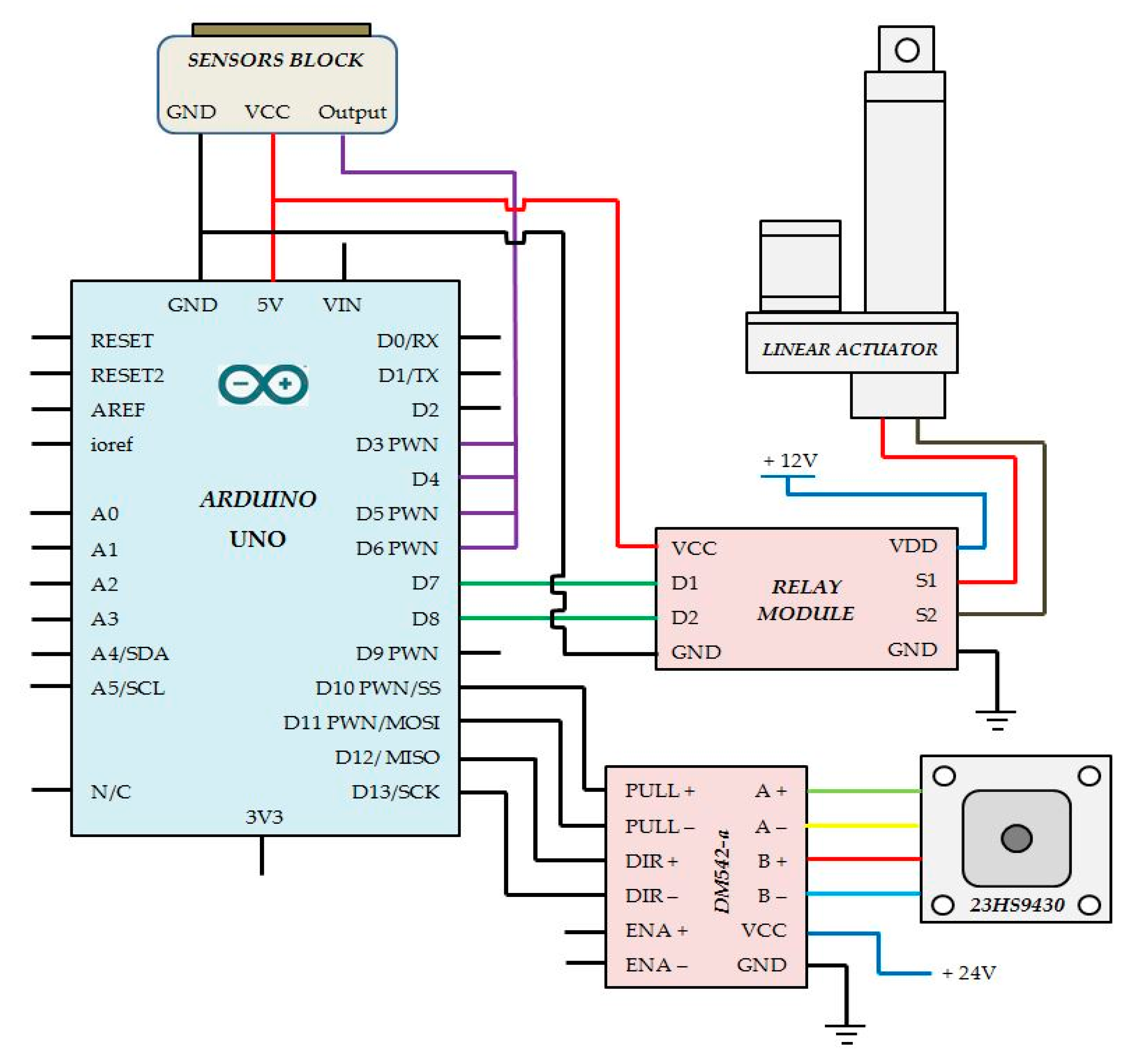
Figure 9.
Designed photovoltaic solar tracker: (a) Front view; and (b) Side view.

Figure 10.
(a) Connection scheme of static installation; and (b) applied installation.

Figure 11.
Average daily production obtained by the solar tracker.
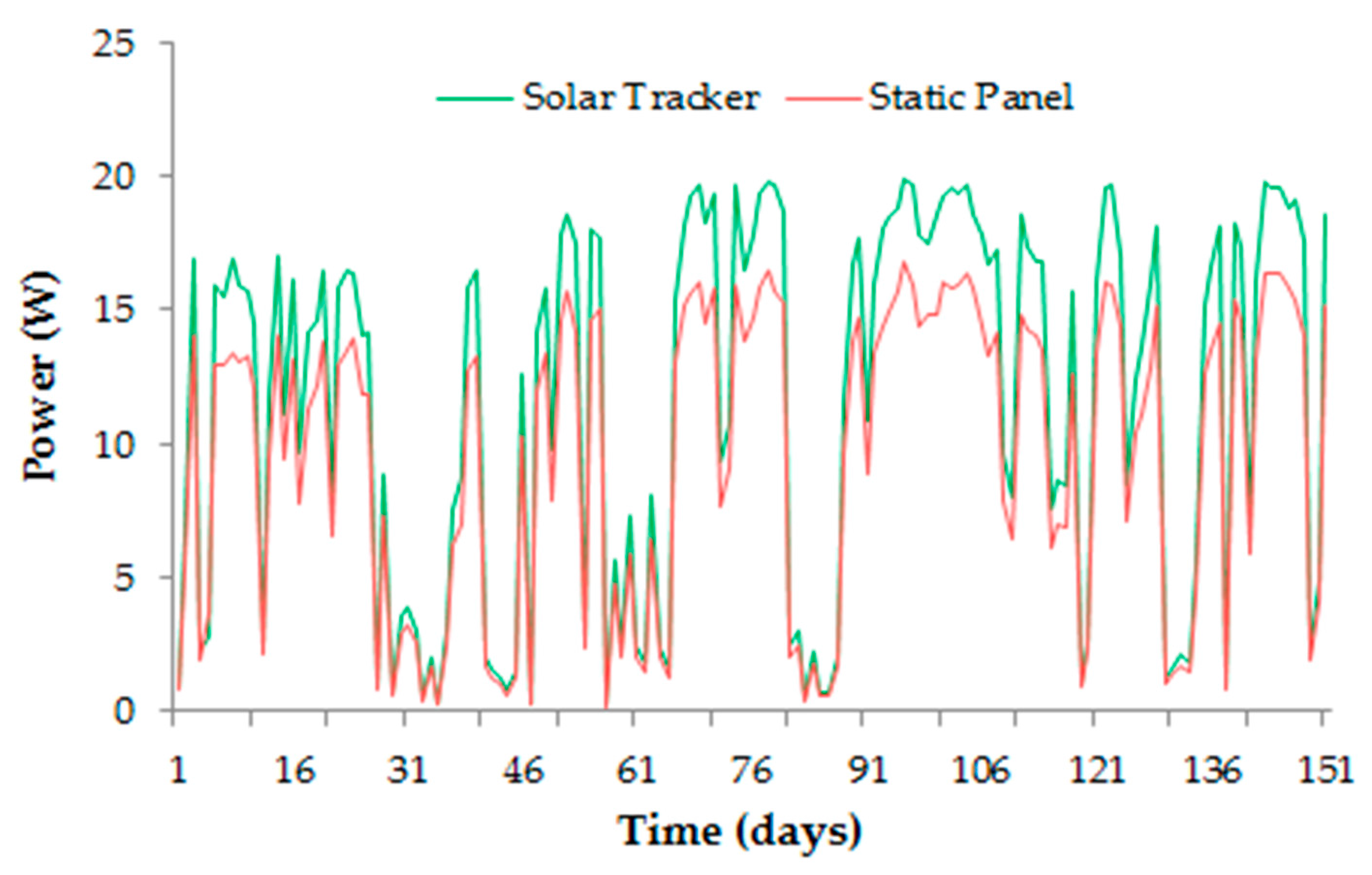
Figure 12.
Correlation between produced power and incident radiation.

Table 1.
Short description of prototype’s components.
| Component * | Description |
|---|---|
| Metal structure | Aluminium structure of 27 kN/m3 according to CTE DB SE-AE [3] |
| Solar panel | Photovoltaic solar panel ISOFOTON of monocrystalline silicon 25 |
| Arduino UNO R3 | Programmable electronic controller for tracking operations ATmega328, 14 digital inputs and 6 analogue inputs, clock of 16 MHz |
| NEMA-23HS9430 | Stepper motor for azimuthal movement |
| LA-10 | Linear actuator for elevation movement |
| Driver DM542a | Controller responsible for the transmission of turning movements to the stepper motor with 0.9 degree/step precision |
| Double relay bridge | Component responsible for activation and moving back the linear actuator, controlled integrally by Arduino sheet |
| BPW34 | Light semiconductors photodiodes responsible for sending the signal to Arduino to activate the movement |
| Victron Energy Battery | Batteries 12 V and 2.1 Ah to provide the tracker and prototype alimentation with the autonomy |
* Moreover, other components such as wiring, protoboards, mortises, etc. were used.
© 2017 by the authors. Licensee MDPI, Basel, Switzerland. This article is an open access article distributed under the terms and conditions of the Creative Commons Attribution (CC BY) license (http://creativecommons.org/licenses/by/4.0/).
Share and Cite
MDPI and ACS Style
Morón, C.; Ferrández, D.; Saiz, P.; Vega, G.; Díaz, J.P. New Prototype of Photovoltaic Solar Tracker Based on Arduino. Energies 2017, 10, 1298. https://doi.org/10.3390/en10091298
AMA Style
Morón C, Ferrández D, Saiz P, Vega G, Díaz JP. New Prototype of Photovoltaic Solar Tracker Based on Arduino. Energies. 2017; 10(9):1298. https://doi.org/10.3390/en10091298
Chicago/Turabian StyleMorón, Carlos, Daniel Ferrández, Pablo Saiz, Gabriela Vega, and Jorge Pablo Díaz. 2017. "New Prototype of Photovoltaic Solar Tracker Based on Arduino" Energies 10, no. 9: 1298. https://doi.org/10.3390/en10091298
Note that from the first issue of 2016, this journal uses article numbers instead of page numbers. See further details here.