Ethyl Methyl Sulfone-Based Electrolytes for Lithium Ion Battery Applications

1
Helmholtz-Institute Münster, IEK-12, Forschungszentrum Jülich GmbH, Corrensstrasse 46, 48149 Münster, Germany
2
MEET Battery Research Center/Institute of Physical Chemistry, University of Münster, Corrensstrasse 46, 48149 Münster, Germany
*
Author to whom correspondence should be addressed.
Energies 2017, 10(9), 1312; https://doi.org/10.3390/en10091312
Submission received: 20 July 2017
/
Revised: 25 August 2017
/
Accepted: 28 August 2017
/
Published: 1 September 2017
(This article belongs to the Section D: Energy Storage and Application)
Abstract
:Sulfone-based electrolytes, known for their higher oxidative stability compared to the typically used organic carbonate-based electrolytes, are considered promising electrolytes for high voltage cathode materials towards the objective of obtaining increased energy density in lithium ion batteries. Nevertheless, sulfones suffer from high viscosity as well as incompatibility with highly graphitic anode materials, which limit their application. In this paper, the effect of fluoroethylene carbonate (FEC) as an electrolyte additive for the application of ethyl methyl sulfone (EMS) electrolytes containing LiPF6 as conducting salt, is studied in graphite-based cells by means of selected electrochemical and spectroscopic methods. In addition, influence of ethylene acetate (EA) as co-solvent on the electrolyte viscosity and conductivity of the EMS-based electrolytes is discussed, revealing improved overall nickel cobalt manganese oxide (NMC)/graphite cell performance. X-ray photoelectron spectroscopy (XPS) measurements provide information about the surface chemistry of the graphite electrodes after galvanostatic cycling. The concept of EA as co-solvent is found to be applicable for other sulfones such as isopropyl methyl sulfone (MeiPrSO2) and ethyl isopropyl sulfone (EtiPrSO2).
1. Introduction
Nowadays, lithium-ion batteries (LIBs) find application in a very broad field of industrial applications [1,2,3] as they are, for instance, used in small portable devices, such as mobile phones or laptop computers, as well as traction batteries in the automotive industry [4]. Unfortunately, the driving range for electric cars (before being recharged) is still too low [5]. For this reason, it is of high importance to develop high voltage and high capacity materials delivering higher energy density compared to the commonly used materials. Numerous efforts towards designing and developing high voltage cathode materials have been made and are still in focus of exhaustive research [6,7]. One of the main obstacles related to application of high voltage cathode materials in LIBs with graphite as anode material, refers to selection of an appropriate electrolyte formulation that fulfills the mandatory minimum requirements. Among them, the electrolyte has to maintain electrochemical stability, which is not the case for the commercially used organic carbonate-based electrolytes containing lithium hexafluorophosphate (LiPF6) as conductive salt [8], as they decompose at a potential of 4.5 V vs. Li/Li+ [9]. On the other hand, the desired electrolyte has to enable formation, like the organic carbonate based electrolytes [10,11,12], of a kinetically stable solid electrolyte interphase (SEI) on the graphite electrode [13,14,15,16]. Sulfones represent a class of solvents reported to be stable at high potentials [17,18,19,20,21]. Furthermore, sulfones, especially ethyl methyl sulfone (EMS), are environmentally friendly and have high flashpoint, thus increasing the safety of the electrolyte. The major barrier to commercialization of sulfone-based electrolytes is their poor compatibility with graphite anodes [22]. One of the possibilities is to replace graphite with lithium titanate (LTO), however this anode material delivers lower energy density [23]. To overcome this challenge, SEI-forming electrolyte additives can be added to the sulfone-based electrolyte, thus leading to the formation of an effective SEI on the graphite surface [13]. A wide variety of SEI additives have been reported in the literature so far [24,25,26,27,28]. In particular, fluoroethylene carbonate (FEC) shows promising results on both graphite anode and high voltage cathode materials [29]. Another challenge arising with the use of sulfone-based electrolytes is related to their low wettability of separator and electrodes as well as their poor electrolyte conductivity when used as electrolyte solvents [22]. Different co-solvents are reported to decrease the viscosity and to increase the conductivity of sulfone-based electrolytes [30]. These co-solvents are for instance dimethyl carbonate (DMC) or ethyl methyl carbonate (EMC) [23,31]. In this paper, the influence of FEC as SEI-forming additive on sulfone-based electrolytes was investigated. Furthermore, by using ethylene acetate (EA) as co-solvent in EMS-based electrolytes, the challenges of poor wettability and poor conductivity were addressed. The electrolyte formulations were investigated in lithium NMC/graphite cells. To analyze the main decomposition products and to show the beneficial behavior of FEC in the electrolyte, X-ray photoelectron spectroscopy (XPS) and XPS sputter depth profiling measurements were performed.
2. Experimental
All electrolytes were prepared in an argon-filled glovebox with water and oxygen content below 0.1 ppm. EMS (99%, ABCR, Karlsruhe, Germany) was heated up to 60 °C prior to electrolyte formulation. LiPF6 (battery grade, BASF, Ludwigshafen, Germany), FEC (battery grade, BASF) and EA (99.8% anhydrous, Sigma Aldrich, St. Louis, MO, USA) were used as received. All investigated electrolytes were formulated by volume percent (vol. %). For reasons of comparison, 1 M LiPF6 in EC/DEC (3:7 wt. %) (LP47, BASF, battery grade) was used as received.
T44 graphite was used as model material for the electrochemical investigations, as its high BET surface area leads to increased electrolyte reduction [32], thus revealing additional minor electrolyte decomposition reactions. Graphite electrodes were composed of 87 wt. % graphite (Imerys, Paris, France) 8 wt. % polyvinylidene difluoride (PVdF, Arkema, Colombes, France) and 5 wt. % conductive additive Super C65 (Imerys). The composition of the lithium manganese oxide spinel, (LMO)-based electrodes was 80 wt. % LMO (Toda, Hiroshima, Japan), 10 wt. % PVdF (Arkema), and 10 wt. % carbon black C65 (Imerys). The preparation procedure of aforementioned electrodes has been described in detail elsewhere [29]. Balanced NMC111 and graphite electrodes (both 12 mm diameter, Litarion, Kamenz, Germany) were used.
The electrochemical measurements were performed in a three-electrode T-cell setup (Swagelok®, Solon, OH, USA) as well as in CR2032 coin cells (Hohsen Corp. Osaka, Japan). Depending on the measurement setup, lithium foil (Albemarle, Charlotte, NC, USA) was used for counter electrode (CE) and reference electrode (RE).
Constant current constant potential (CCCP) measurements were performed at 20 °C using a battery cycler (MACCOR Series 4000, Tulsa, OK, USA). The graphite/Li cells were cycled in the potential range between 0.02 V–1.50 V vs. Li/Li+ starting with three formation cycles at charge/discharge rate of 37.2 mA·g−1 (corresponding to C/10, when considering a practical specific capacity of 372 mAh·g−1). After the formation sequence, cells were cycled at charge/discharge rate of 1C (372 mA·g−1). Each intercalation step (1C) was followed by a constant potential step with 1 h duration at a potential of 0.025 V vs. Li/Li+. The cathode capacity-limited NMC/graphite cells (15% oversized anode) were cycled with five formation cycles at 0.1C. After the formation, cells were cycled at 1C over 100 charge/discharge cycles in the voltage range from 3 V to 4.3 V.
AC impedance measurements were conducted to determine the conductivity of the electrolyte. All measurements were carried out on a Solartron 1260A (AMETEK, Berwyn, PA, USA) impedance gain phase analyzer, connected to a Solartron 1287A (AMETEK, Berwyn, PA, USA) potentiostat using a customized cell having two stainless steel disk-electrodes. A frequency range from 1 kHz to 1 MHz using an AC amplitude of 20 mV was applied to the cell in the temperature range from −40 °C to 60 °C, regulated via a climate chamber (Binder, Tuttlingen, Germany). Differences in the determined conductivity values are in-between the error margin of the system.
The contact angle measurements were performed on a Drop Shape Analyzer DSA 100 (Krüss, Hamburg, Germany) placed in a dry room (dew point: −65 °C). For each measurement, a drop of electrolyte was dispersed on a surface of the Celgard 2500 (Celgard, Charlotte, NC, USA) separator.
For the X-ray photoelectron spectroscopy (XPS) investigations, an AXIS Ultra DLD (Shimadzu Corporation, Kyoto, Japan) was used. An area of 300 µm × 700 µm was irradiated, while using a filament voltage of 12 kV, an emission current of 10 mA and a pass energy of 20 eV. The obtained spectra were calibrated against the carbon signal at 284.5 eV. For the XPS sputter depth profiling measurements, a sputter crater diameter of 1.1 mm, an emission current of 8 mA and a filament voltage of 0.5 kV as well as a pass energy of 40 eV and a 110 μm aperture were applied. The fitting of the resulted spectra was performed by means of CasaXPS.
3. Results and Discussion
As shown in Figure 1a, EMS-based electrolyte is not capable of forming an effective SEI on graphite. The decomposition of EMS starts at a potential of 1.2 V vs. Li/Li+ (Figure 1a). For the application of EMS-based electrolytes, the use of SEI-forming additives is inevitable. With this in line, different concentrations of FEC were considered as SEI-forming additive for the application of EMS-based electrolytes in graphite/Li cells. The potential profiles of afore described electrolyte formulations are depicted in Figure 1.
As seen in Figure 1b, the presence of 1% FEC does not prevent the decomposition of EMS, as decomposition of the electrolyte on the electrode deteriorates the performance of the cell in terms of low Coulombic efficiency and reversible capacity (Table 1). However, when 2% FEC was added to the 1 M LiPF6 in the EMS-based electrolyte (Figure 1c), decomposition of EMS is inhibited, at least in the first cycle, thus enabling reversible lithium intercalation and deintercalation into/from the graphite structure, as indicated by the formation of the respective potential plateaus at potential below 0.2 V vs. Li/Li+ [33]. In addition, the irreversible capacity in the first cycle and the potential difference due to IR drop and overpotential (=“potential-drop”) are lower compared to the values obtained for 1% FEC-containing electrolyte (Figure 1a), which results in higher energy efficiencies [34]. When increasing the amount of FEC to 3% or 4%, the Coulombic efficiency increases, whereas the potential-drop decreases. Addition of more than 4% of FEC to the electrolyte formation has no further influence on the electrochemical performance of the graphite/Li cell. For this reason, higher concentrations of FEC are not shown. Table 1 summarizes the Coulombic efficiency and the measured potential drop values of the first cycle for the aforementioned electrolyte formulations.
Pronounced decomposition of EMS on the graphite electrode in the first cycle is prevented, when more than 1% FEC is added to the electrolyte formulation. To further investigate the minimum amount of FEC required for achieving stable cycling behavior, long-term cycling measurements were performed (Figure 2).
The cell containing 1% FEC (Figure 2a) does not reach the theoretical capacity value of graphite (372 mAh·g−1) [35], due to continuous reduction of EMS on graphite electrode (compare Figure 1b). In the first cycle, the specific discharge capacity reaches a value of 50 mAh·g−1. Moreover, the cycling behavior over 100 charge/discharge cycles is not stable. In case of the electrolyte containing 2% FEC, a specific discharge capacity of 280 mAh·g−1 is reached in the formation cycles (Figure 2b). After the formation step, the specific capacity decreases and the Coulombic efficiency values indicate neither a stable cycling performance nor complete prevention of the EMS decomposition after the first cycle. Therefore, the amount of FEC was increased to 3% (Figure 2c). The cell cycled with 3% FEC-containing electrolyte shows more stable cycling behavior compared to the cells containing 1% and 2% FEC. In the initial cycles, a specific discharge capacity of 240 mAh·g−1 is achieved. Increasing the amount of FEC in the electrolyte to 4%, decomposition of EMS-based electrolyte is even more suppressed, as depicted in Figure 2d. In the first, formation cycles, a specific discharge capacity of 325 mAh·g−1 is reached. Over 100 charge/discharge cycles, a stable cycling behavior without any fading can be observed. The capacity retention (discharge capacity (cycle 100)/discharge capacity (cycle 7)) amounts to 98.9%. The CCCP measurements showed that addition of 4% FEC to the 1 M LiPF6 in EMS electrolyte results in the best long-term cycling behavior in graphite/Li cells compared to lower amounts of FEC. Increased amount of FEC (>4%) does not improve the overall electrochemical performance, including long-term cycling. Due to the high viscosity of EMS, leading to a low conductivity, an EMS-based electrolyte would never compete with the carbonate-based electrolyte. To overcome this challenge the EMS-based electrolyte had to be modified by adding a dilution agent to the formulation. Ethylene carbonate (EA) is a well-known co-solvent with excellent properties regarding its viscosity and conductivity. Having in mind, that the performance of the electrolyte is strongly related to its conductivity. Further advantages of EA are its good environmental friendliness and the ability to solvate the lithium salt as well as the high wettability of the separator. Hence, EA was added to the high viscose EMS-based electrolyte, resulting in an electrolyte with good conductivity, compatible with the standard carbonate-based electrolyte (Figure 3). Decreasing the amount of EA leads to a lower conductivity of the electrolyte formulation. Increasing the amount of EA would enhance the flammability. Therefore, it desirable to keep the amount of EMS as high as possible.
Nevertheless, EMS-based electrolytes are known for much lower ionic conductivity, originating from their high viscosity, compared to the state-of-the-art organic carbonate-based electrolytes. Therefore, ethylene acetate (EA) as low viscosity co-solvent, known for enabling high ionic conductivities in the resultant electrolyte, was added to the 1 M LiPF6 in EMS electrolyte formulation. The obtained conductivity values of selected electrolytes are shown in Figure 3.
The determined conductivities of 1 M LiPF6 in EMS + 4% FEC are much lower compared to the values obtained for 1 M LiPF6 in EC/DEC (3:7) in the temperature range from −40 °C to 60 °C. Because of the limited liquid range, pure EMS-based electrolytes are not conductive in the temperature range from −20 °C to 0 °C. At 20 °C, the conductivity amounts to 1.73 mS·cm−1 and increases further to 4.81 mS·cm−1 at 60 °C. In contrast to this, the conductivity of the carbonate-based electrolyte reaches a value of 3.98 mS·cm−1 at 0 °C, increasing to 5.58 mS·cm−1 at 20 °C and 9.85 mS·cm−1 at 60 °C. Compared to this, a high conductivity values can be achieved, in 1 M LiPF6 in EMS electrolyte containing 4% FEC as additive. At −20 °C, a conductivity value of 5.65 mS·cm−1 is reached, increasing to 8.08 mS·cm−1 at 0 °C. At 20 °C, the conductivity of the electrolyte reaches a value of 9.58 mS·cm−1. Further increase in temperature results in a conductivity of 11.21 mS·cm−1 at 60 °C. After addition of EA to the EMS-based electrolyte in a 1:1 (EMS/EA) ratio, the conductivity of the 1 M LiPF6 in EMS/EA (1:1) + 4% FEC electrolyte is comparable to the value of the carbonate-based electrolyte (5.23 mS·cm−1). The addition of EA to the EMS-based electrolyte increases not only the conductivity, but also influences the wettability of the electrolyte formulation, enabling its applicability on different separators. In the following, the values obtained from the contact angle measurement are depicted. In the related measurement, a very low contact angle (Θ) indicates a high wettability. For the 1 M LiPF6 in EMS electrolyte, a contact angle of (103 ± 3), was determined as an average value from four measurements performed on a Celgard 2500 separator. Compared to this very high value, the contact angle of the commercially used 1 M LiPF6 in EC:DEC (3:7) amounts to (57 ± 5), thus ensuring better wettability. Addition of EA to the EMS electrolyte (1:1 ratio), results in the contact angle value of (60 ± 3), which is similar to the one obtained for the reference electrolyte.
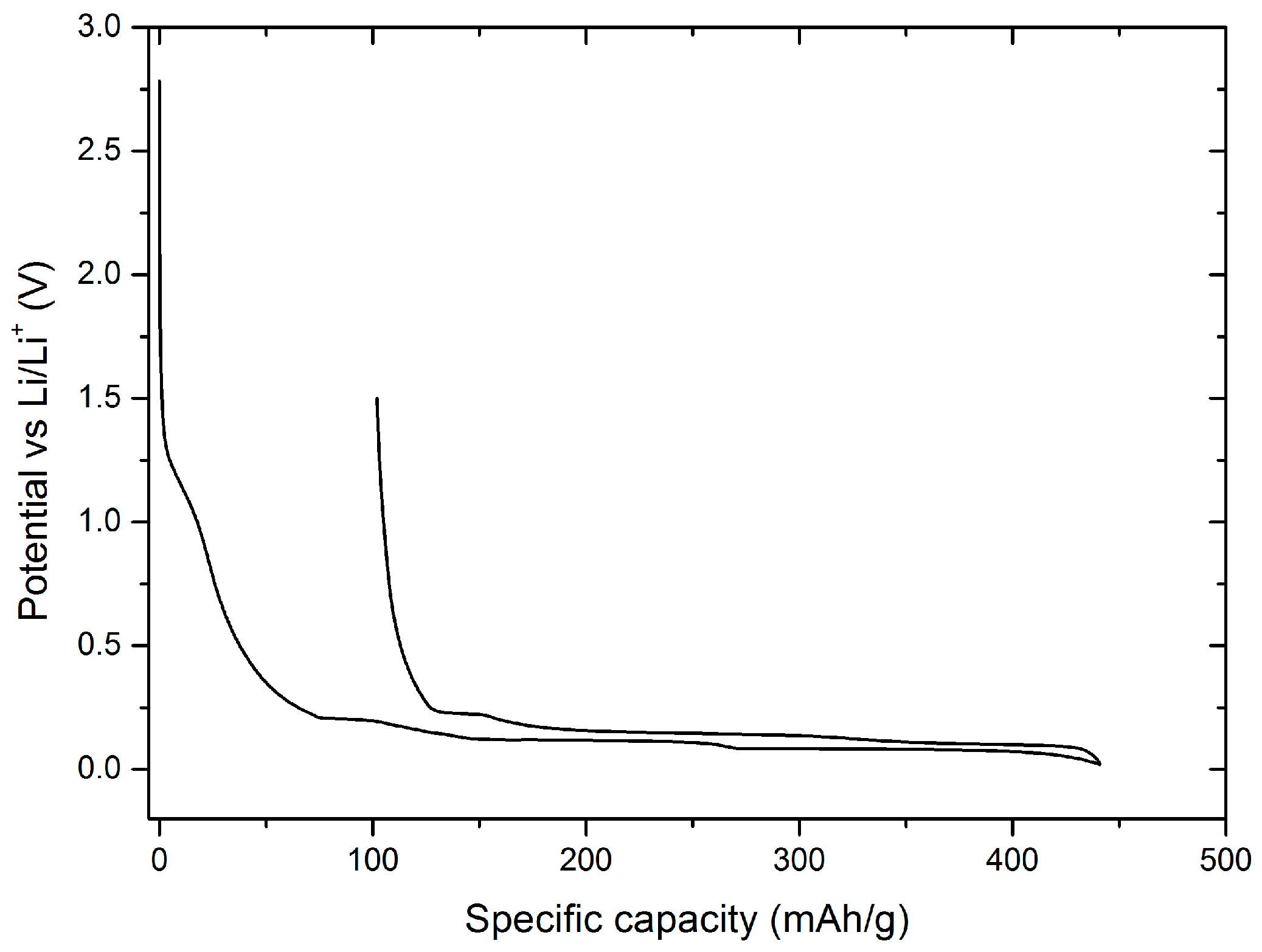
With both, conductivity as well as contact angle measurements it is shown, that the addition of EA to the EMS-based electrolyte has a significant influence on improved performance. In the following, the EA/EMS-based electrolytes were characterized by means of selected electrochemical methods on both anode and cathode materials, as well as in NMC/graphite cells. To investigate the electrochemical stability of 1 M LiPF6 in EMS:EA (1:1) with 4% FEC electrolyte and in particular the influence of EA on the stability against graphite electrodes, a potential vs. specific capacity diagram of the first cycle of a graphite/Li cells is shown in Figure 4.
The first electrolyte decomposition starts at approximately 1.5 V vs. Li/Li+, which is attributed to a reaction of the SEI-forming additive FEC. While decreasing the potential to 0.02 V, the typical intercalation plateaus of lithium ions into graphite [36,37] are discernible. A small potential-drop (0.003 V) indicates a low-restive SEI, similar to the SEI formed with 1 M LiPF6 in EMS-based electrolyte containing 4% FEC. By increasing the potential to 1.5 V vs. Li/Li+, the deintercalation of lithium ions takes place. The Coulombic efficiency amounts to 76.9%. The addition of FEC to the EMS/EA solvent mixture is still required, as, similarly to EMS, EA is not able to form an effective SEI on graphite during constant current cycling. To prove this assumption, XPS sputter depth profiling measurements were carried out on graphite electrodes after constant current cycling in graphite/Li cells containing investigated electrolyte formulations.
Figure 5a depicts the XPS S 2p core spectrum of a graphite electrode cycled with the 1 M LiPF6 in EMS electrolyte. The signal at 167.59 eV is attributed to EMS, which is decomposed on the graphite surface. During sputtering, this signal decreased slightly indicating a very thick decomposition layer on the electrode. Compared to the aforementioned XPS S 2p core spectra, the core spectra of graphite cycled with 1 M LiPF6 in EMS:EA (1:1) electrolyte (Figure 5b) look very similar, thus showing that EA is not able to protect EMS against decomposition. In both cases, the sulfur signal cannot stem from impurities present on the pristine graphite surface, since the reference measurement on a non-cycled graphite electrode does not show any sulfur signal (Figure 5e). When adding 1% FEC to the EMS/EA electrolyte, the sulfur signal in the XPS S 2p core spectrum decreases (Figure 5c) compared to the signal obtained without FEC. Increasing the amount of FEC to 4% (Figure 5d) shows nearly no sulfur signal in the XPS S 2p core spectrum of the cycled graphite electrode anymore. A quantitative analysis of the XPS data shows a strong decrease of atomic sulfur concentration within the formed SEI. Figure 6 depicts relative composition of the organic and inorganic part of the SEI, as well as the sulfur content. When using 1 M LiPF6 in EMS as electrolyte, sulfur content amounts to 12% due to the massive decomposition of the EMS solvent. Decreasing the amount of EMS in the electrolyte formulation to 50%, by adding EA, lowers the amount of sulfur, from 12% relative composition to 6%. Due to the ongoing decomposition of EMS and EA, relative composition of inorganic as well as organic part rises. Overall, EA does not inhibit decomposition of EMS on the graphite surface. By adding FEC to the electrolyte formulation, decomposition of EMS and with this the relative composition of sulfur in the SEI decreases from 6% to 2%, thus indicating formation of a passivation layer. The proportion regarding the inorganic and organic part is not as expected. The decomposition of FEC on the graphite surface, results in formation of hydrofluoric acid (HF) and vinylene carbonate (VC). HF reacts on the graphite surface to lithium fluoride (LiF) whereas VC polymerizes on the electrode surface. We would expect an increase of the relative composition of the inorganic part and a decrease of the relative composition of the organic part. The obtained results for the electrolyte formulation containing 1% FEC may be correlated to the mean error deviation of the system. Increased amount of FEC (4%) reduces the atomic sulfur concentration within in the SEI to 1%. Nearly no EMS decomposition is observed on the electrode surface indicating formation of an effective SEI. When using 4% FEC in the electrolyte formulation, the inorganic part of the SEI increases, whereas the organic part of the SEI decreases, compared to the results obtained for the cell without FEC. This can be attributed to the previously described decomposition of FEC. The obtained XPS results are in good agreement with electrochemical measurements (Figure 1 and Figure 2).
Having this in mind, as well as the results obtained from the CCCP measurement on graphite with EMS and different FEC amounts (Figure 2) in the following measurements 4% FEC were added to the investigated electrolyte formulation. In order to get a deeper insight on the influence of EA on the cycling performance, long-term cycling behavior was investigated in graphite/Li cells (Figure 7).
The CCCP measurement of graphite/Li cells indicates a stable cycling performance, excluding capacity fading over 100 charge/discharge cycles. In the formation cycles, a specific discharge capacity of 344 mAh·g−1 is achieved. After the formation cycles, the specific capacity increases to 353 mAh·g−1 in the 5th cycle. This value is comparable to the one received in the CCCP measurement of 1 M LiPF6 in EMS without EA as co-solvent. Over 100 charge/discharge cycles, the Coulombic efficiency values indicate a stable cycling performance. To show the anodic stability of EMS-based electrolytes, linear sweep voltammetry (LSV) measurements on LMO are depicted in Figure 8.
The electrochemical stability window show, that all three investigated electrolytes (1 M LiPF6 in EMS, 1 M LiPF6 in EMS + 4% FEC and 1 M LiPF6 in EMS:EA + 4% FEC) are stable on LMO up to a potential of 5 V vs. Li/Li+. The peak maxima of the deintercalation peaks of LMO are positioned at 4.05 V vs. Li/Li+ and 4.16 V vs. Li/Li+, a further proof that the addition of EA as co-solvent to the EMS-based electrolyte has no negative effect on the electrochemical stability of the electrolyte. As known from the literature, aluminum dissolution depends on various factors, including aluminum surface structure, electrochemical operation conditions as well as the nature and type of the electrolyte. EMS-based electrolytes have been intensively studied in respect to aluminum current collector dissolution by Meister et al. [38]. In this contribution constant current measurements using aluminum current collector as WE, were conducted and the electrode polarized to 5 V vs. Li/Li+ for 24 h. Thereafter, SEM studies were performed to quantify aluminum dissolution. The authors pointed out that an electrolyte based on 1 M LiPF6 in EMS shows no pit formation (areas where aluminum dissolution took place) on the aluminum current collector whereas 1 M LITFSI in EMS leads to extensive pit formation. Due to the addition of LITFSI, no stable passivation layer can be formed on the aluminum foil, triggered by the high dielectric constant of EMS. The absence of aluminum dissolution spots provides an indication of the formation of a sufficiently stable passivation layer, formed by the conducting salt LiPF6, which inhibits the anodic dissolution of aluminum.
With this in line, electrochemical performance in a cell setup, where reactions at the anode and cathode influence each other [39,40], 1 M LiPF6 in EMS:EA (1:1) with 4% FEC electrolyte, was investigated. Decreasing the amount of EA leads to a lower conductivity of the electrolyte formulation. Increasing the amount of EA would enhance the flammability. The cycling profile of NMC/graphite cell containing the aforementioned electrolyte composition is shown in Figure 9.
Formation of an effective SEI on graphite in the above mentioned cell set-up, as achieved by the first five cycles were performed at a rate of 0.1C and resulted in a specific capacity of 173 mAh·g−1. The Coulombic efficiency reaches a value of 99.3%. After the formation cycles, the cell was cycled with 1C, resulting in a stable long-term cycling. The capacity retention amounts to 99.7% in the 20th cycle to 99.3% in the 60th cycle and to 98.9% in the 100th cycle.
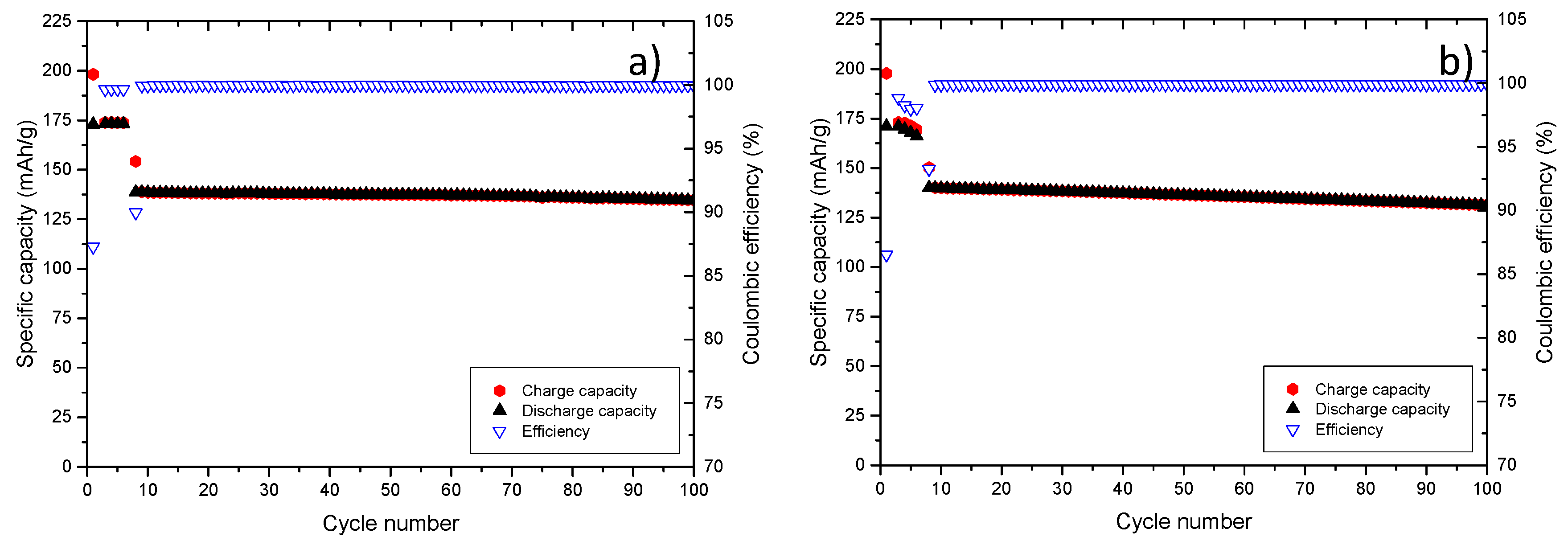
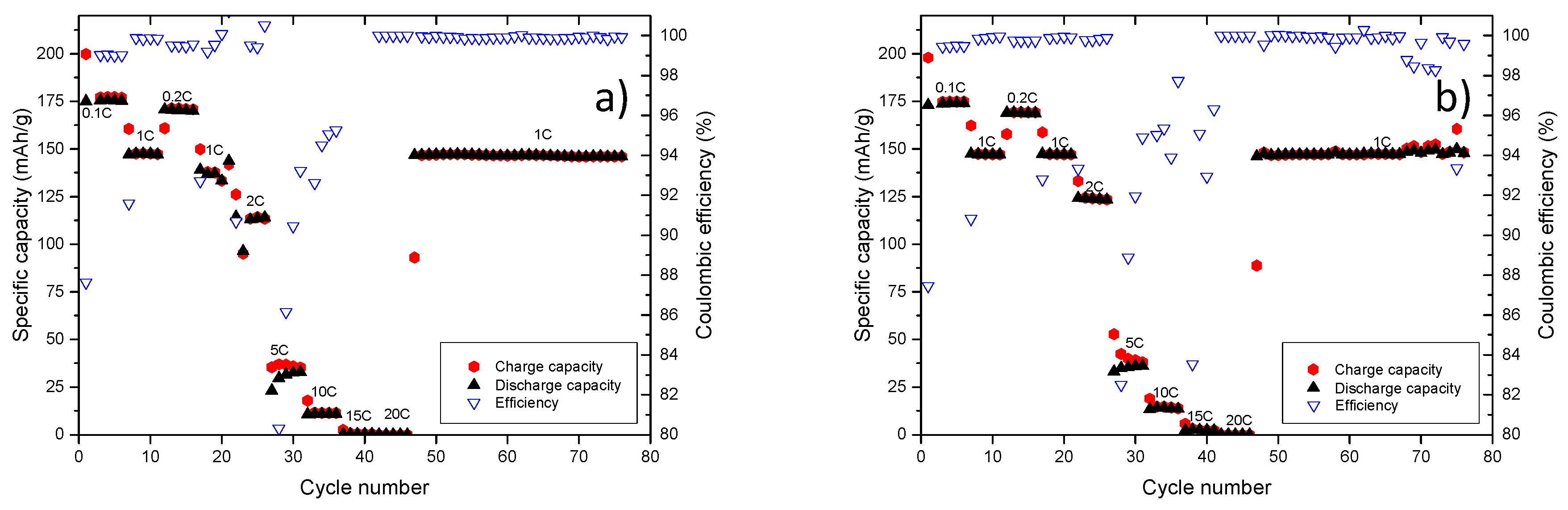
A further proof for comparable electrochemical performance of the EMS/EA-based electrolyte to the carbonate-based electrolyte is provided by the charge/discharge rate measurement, as depicted in Figure 10. After the charge/discharge test up to 20C, cells were cycled with 1C for 30 additional charge discharge cycles, as shown in Figure 10, depicting stable cycling performance and comparable specific capacity values.
The concept of using EA as co-solvent and FEC as SEI-forming additive was extended to other sulfones, namely isopropyl methyl sulfone (MeiPrSO2) and ethyl isopropyl sulfone (EtiPrSO2). For this reason, constant current constant voltage (CCCV) measurements of NMC/graphite cells with the aforementioned sulfones are discussed in the following. Similar to the cycling performance of 1 M LiPF6 in EMS:EA (1:1) with 4% FEC electrolyte on NMC also the CCCV measurement of 1 M LiPF6 in EtiPrSO2:EA (1:1) with 4% FEC on graphite exhibits a good cycling stability, as shown in Figure 11.
The capacity retention amounts to 96.9% in the 100th cycle. In contrast to the other sulfone-based electrolytes, the cycling profiles of 1 M LiPF6 in MeiPrSO2:EA (1:1) with 4% FEC indicate a strong capacity fading. The capacity retention amounts to 93.5% in the 100th cycle. It may be concluded, that EMS shows a better long term cycling behavior compared to the other two investigated sulfone-based electrolytes. Furthermore, the concept of using EA as co-solvent in sulfone-based electrolytes as well as the presence of FEC as SEI additive represent a successful approach towards alternative nonaqueous electrolyte formulations for application in lithium ion batteries.
4. Conclusions
In this contribution, the concept of FEC as SEI-forming electrolyte additive and EA as electrolyte co-solvent was introduced for sulfone-based electrolytes. The optimal amount of FEC in the 1 M LiPF6 in EMS electrolyte, used to achieve stable cycling performance on graphite electrodes was determined. It was shown that the addition of 4% FEC to 1 M LiPF6 in an EMS-based electrolyte results in a stable long-term cycling performance of graphite/Li cells. Further tailoring of this electrolyte, in terms of higher conductivity and wettability, was attained by using EA as co-solvent. The conductivity value of 1 M LiPF6 in EMS:EA (1:1) + 4% FEC at 20 °C (5.23 mS·cm−1) is comparable to the one of the commercially available carbon-based electrolyte (5.58 mS·cm−1), whereas the conductivity value (1.73 mS·cm−1) of pure 1 M LiPF6 in EMS is much lower. Contact angle measurements further confirmed similar behavior of the 1 M LiPF6 in EMS:EA (1:1) with 4% FEC to the carbonate-based electrolyte, resulting in a contact angle of ≈ 60°. On the other hand, the contact angle of the EMS-based electrolyte without EA shows a much higher value (103 ± 3)° leading to a lower wettability of the used Celgard 2500 separator. CCCP measurements of graphite using a 1 M LiPF6 in EMS:EA based electrolyte indicating no negative effect of EA on the cycling performance of the cell. Results obtained by XPS measurements revealed decomposition of EMS as well as EA on graphite, resulting in a thick decomposition layer on the graphite surface. The decomposition of EMS (sulfur signal at 168 eV) was not observed when adding 4% FEC to the 1 M LiPF6 in EMS:EA electrolyte formulation. CCCP measurements of graphite/Li cells, using an EMS-based electrolyte with and without EA, showed that in both cases that 4% FEC are required to preventing the decomposition of the electrolyte over 100 charge/discharge cycles. In the NMC/graphite cell configuration, a stable cycling performance was achieved with the 1M LiPF6 in EMS:EA + 4% FEC electrolyte. In addition, the concept of using EA and FEC in combination with EMS-based electrolyte is found applicable for other sulfones, such as EtiPrSO2 and MeiPrSO2.
Acknowledgments
Financial support by the German Federal Ministry for Education and Research (BMBF) within the project Electrolyte Lab, 4E (project reference 03X4632) is gratefully acknowledged. The authors would like to thank B. Streipert for his support in analyzing the XPS data.
Author Contributions
Peter Hilbig, Isidora Cekic-Laskovic and Martin Winter conceived and designed the experiments; Peter Hilbig and Lukas Ibing performed the experiments; Peter Hilbig, Lukas Ibing, Ralf Wagner, Isidora Cekic-Laskovic and Martin Winter analyzed the data; Peter Hilbig and Isidora Cekic-Laskovic wrote the paper.”
Conflicts of Interest
The authors declare no conflict of interest.
References
- Winter, M.; Brodd, R.J. What are batteries, fuel cells, and supercapacitors? Chem. Rev. 2004, 104, 4245–4269. [Google Scholar] [CrossRef] [PubMed]
- Wagner, R.; Preschitschek, N.; Passerini, S.; Leker, J.; Winter, M. Current research trends and prospects among the various materials and designs used in lithium-based batteries. J. Appl. Electrochem. 2013, 43, 481–496. [Google Scholar] [CrossRef]
- Besenhard, J.O.; Winter, M. Insertion reactions in advanced electrochemical energy storage. Pure Appl. Chem. 1998, 70, 603–608. [Google Scholar] [CrossRef]
- Andre, D.; Kim, S.-J.; Lamp, P.; Lux, S.F.; Maglia, F.; Paschos, O.; Stiaszny, B. Future generations of cathode materials: An automotive industry perspective. J. Mater. Chem. 2015, 3, 6709–6732. [Google Scholar] [CrossRef]
- Lu, L.; Han, X.; Li, J.; Hua, J.; Ouyang, M. A review on the key issues for lithium-ion battery management in electric vehicles. J. Power Sources 2013, 226, 272–288. [Google Scholar] [CrossRef]
- Fey, G.T.-K.; Lu, C.-Z.; Kumar, T.P. Preparation and electrochemical properties of high-voltage cathode materials, LiMyNi0.5−yMn1.5O4 (M = Fe, Cu, Al, Mg; y = 0.0–0.4). J. Power Sources 2003, 115, 332–345. [Google Scholar] [CrossRef]
- Qi, X.; Blizanac, B.; DuPasquier, A.; Lal, A.; Niehoff, P.; Placke, T.; Oljaca, M.; Li, J.; Winter, M. Influence of Thermal Treated Carbon Black Conductive Additive on the Performance of High Voltage Spinel Cr-Doped LiNi0.5Mn1.5O4 Composite Cathode Electrode. J. Electrochem. Soc. 2015, 162, A339–A343. [Google Scholar] [CrossRef]
- Tan, S.; Ji, Y.J.; Zhang, Z.R.; Yang, Y. Recent Progress in Research on High-Voltage Electrolytes for Lithium-Ion Batteries. ChemPhysChem 2014, 15, 1956–1969. [Google Scholar] [CrossRef] [PubMed]
- Xu, K. Electrolytes and Interphases in Li-Ion Batteries and Beyond. Chem. Rev. 2014, 114, 11503–11618. [Google Scholar] [CrossRef] [PubMed]
- Winter, M.; Imhof, R.; Joho, F.; Novak, P. FTIR and DEMS investigations on the electroreduction of chloroethylene carbonate-based electrolyte solutions for lithium-ion cells. J. Power Sources 1999, 81, 818–823. [Google Scholar] [CrossRef]
- Schmitz, R.W.; Murmann, P.; Schmitz, R.; Müller, R.; Krämer, L.; Kasnatscheew, J.; Isken, P.; Niehoff, P.; Nowak, S.; Röschenthaler, G.-V.; et al. Investigations on novel electrolytes, solvents and SEI additives for use in lithium-ion batteries: Systematic electrochemical characterization and detailed analysis by spectroscopic methods. Prog. Solid State Chem. 2014, 42, 65–84. [Google Scholar] [CrossRef]
- Amereller, M.; Schedlbauer, T.; Moosbauer, D.; Schreiner, C.; Stock, C.; Wudy, F.; Zugmann, S.; Hammer, H.; Maurer, A.; Gschwind, R.M.; et al. Electrolytes for lithium and lithium ion batteries: From synthesis of novel lithium borates and ionic liquids to development of novel measurement methods. Prog. Solid State Chem. 2014, 42, 39–56. [Google Scholar] [CrossRef]
- Winter, M. The Solid Electrolyte Interphase—The Most Important and the Least Understood Solid Electrolyte in Rechargeable Li Batteries. Int. J. Res. Phys. Chem. Chem. Phys. 2009, 223, 1395–1406. [Google Scholar] [CrossRef]
- Winter, M.; Besenhard, J.O.; Spahr, M.E.; Novak, P. Insertion electrode materials for rechargeable lithium batteries. Adv. Mater. 1998, 10, 725–763. [Google Scholar] [CrossRef]
- Peled, E.; Menachem, C.; BarTow, D.; Melman, A. Improved graphite anode for lithium-ion batteries-Chemically bonded solid electrolyte interface and nanochannel formation. J. Electrochem. Soc. 1996, 143, L4–L7. [Google Scholar] [CrossRef]
- Olivier, J.P.; Winter, M. Determination of the absolute and relative extents of basal plane surface area and “non-basal plane surface” area of graphites and their impact on anode performance in lithium ion batteries. J. Power Sources 2001, 97, 151–155. [Google Scholar] [CrossRef]
- Xu, K.; Angell, C.A. Sulfone-based electrolytes for lithium-ion batteries. J. Electrochem. Soc. 2002, 149, A920–A926. [Google Scholar] [CrossRef]
- Xu, K.; Angell, C.A. High Anodic Stability of a New Electrolyte Solvent: Unsymmetric Noncyclic Aliphatic Sulfone. J. Electrochem. Soc. 1998, 145, L70–L72. [Google Scholar] [CrossRef]
- Wu, F.; Zhou, H.; Bai, Y.; Wang, H.; Wu, C. Toward 5 V Li-Ion Batteries: Quantum Chemical Calculation and Electrochemical Characterization of Sulfone-Based High-Voltage Electrolytes. ACS Appl. Mater. Interfaces 2015, 7, 15098–15107. [Google Scholar] [CrossRef] [PubMed]
- Hofmann, A.; Hanemann, T. Novel electrolyte mixtures based on dimethyl sulfone, ethylene carbonate and LiPF6 for lithium-ion batteries. J. Power Sources 2015, 298, 322–330. [Google Scholar] [CrossRef]
- Abouimrane, A.; Belharouak, I.; Amine, K. Sulfone-based electrolytes for high-voltage Li-ion batteries. Electrochem. Commun. 2009, 11, 1073–1076. [Google Scholar] [CrossRef]
- Xu, K. Nonaqueous liquid electrolytes for lithium-based rechargeable batteries. Chem. Rev. 2004, 104, 4303–4417. [Google Scholar] [CrossRef] [PubMed]
- Xue, L.; Lee, S.-Y.; Zhao, Z.; Angell, C.A. Sulfone-carbonate ternary electrolyte with further increased capacity retention and burn resistance for high voltage lithium ion batteries. J. Power Sources 2015, 295, 190–196. [Google Scholar] [CrossRef]
- Zhang, L.; Ma, Y.; Cheng, X.; Zuo, P.; Cui, Y.; Guan, T.; Du, C.; Gao, Y.; Yin, G. Enhancement of high voltage cycling performance and thermal stability of LiNi1/3Co1/3Mn1/3O2 cathode by use of boron-based additives. Solid State Ion. 2014, 263, 146–151. [Google Scholar] [CrossRef]
- Zheng, X.; Huang, T.; Pan, Y.; Wang, W.; Fang, G.; Wu, M. High-voltage performance of LiNi1/3Co1/3Mn1/3O2/graphite batteries with di(methylsulfonyl) methane as a new sulfone-based electrolyte additive. J. Power Sources 2015, 293, 196–202. [Google Scholar] [CrossRef]
- Wagner, R.; Brox, S.; Kasnatscheew, J.; Gallus, D.R.; Amereller, M.; Cekic-Laskovic, I.; Winter, M. Vinyl sulfones as SEI-forming additives in propylene carbonate based electrolytes for lithium-ion batteries. Electrochem. Commun. 2014, 40, 80–83. [Google Scholar] [CrossRef]
- Santner, H.J.; Korepp, C.; Winter, M.; Besenhard, J.O.; Möller, K.-C. In-situ FTIR investigations on the reduction of vinylene electrolyte additives suitable for use in lithium-ion batteries. Anal. Bioanal. Chem. 2004, 379, 266–271. [Google Scholar] [CrossRef] [PubMed]
- Korepp, C.; Kern, W.; Lanzer, E.A.; Raimann, P.R.; Besenhard, J.O.; Yang, M.H.; Möller, K.C.; Shieh, D.T.; Winter, M. Isocyanate compounds as electrolyte additives for lithium-ion batteries. J. Power Sources 2007, 174, 387–393. [Google Scholar] [CrossRef]
- Kasnatscheew, J.; Schmitz, R.W.; Wagner, R.; Winter, M.; Schmitz, R. Fluoroethylene Carbonate as an Additive for γ-Butyrolactone Based Electrolytes. J. Electrochem. Soc. 2013, 160, A1369–A1374. [Google Scholar] [CrossRef]
- Demeaux, J.; De Vito, E.; Lemordant, D.; Le Digabel, M.; Galiano, H.; Caillon-Caravanier, M.; Claude-Montigny, B. On the limited performances of sulfone electrolytes towards the LiNi0.4Mn1.6O4 spinel. Phys. Chem. Chem. Phys. 2013, 15, 20900–20910. [Google Scholar] [CrossRef] [PubMed]
- Xue, L.; Ueno, K.; Lee, S.-Y.; Angell, C.A. Enhanced performance of sulfone-based electrolytes at lithium ion battery electrodes, including the LiNi0.5Mn1.5O4 high voltage cathode. J. Power Sources 2014, 262, 123–128. [Google Scholar] [CrossRef]
- Winter, M.; Novak, P.; Monnier, A. Graphites for lithium-ion cells: The correlation of the first-cycle charge loss with the Brunauer-Emmett-Teller surface area. J. Electrochem. Soc. 1998, 145, 428–436. [Google Scholar] [CrossRef]
- Wagner, M.R.; Albering, J.H.; Möller, K.C.; Besenhard, J.O.; Winter, M. XRD evidence for the electrochemical formation of Li+(PC)yCn- in PC-based electrolytes. Electrochem. Commun. 2005, 7, 947–952. [Google Scholar] [CrossRef]
- Meister, P.; Jia, H.; Li, J.; Kloepsch, R.; Winter, M.; Placke, T. Best Practice: Performance and Cost Evaluation of Lithium Ion Battery Active Materials with Special Emphasis on Energy Efficiency. Chem. Mater. 2016, 28, 7203–7217. [Google Scholar] [CrossRef]
- Winter, M.; Besenhard, J.O. Lithiated Carbons. In Handbook of Battery Materials; Wiley-VCH: Weinheim, Germany, 2007; pp. 383–418. [Google Scholar]
- Winter, M.; Besenhard, J.O. Electrochemical Intercalation of Lithium into Carbonaceous Materials. In Lithium Ion Batteries; Wiley-VCH: Weinheim, Germany, 2007; pp. 127–155. [Google Scholar]
- Wakihara, M.; Yamamoto, O. Lithium Ion Batteries: Fundamentals and Performance; John Wiley & Sons: Hoboken, NJ, USA, 2008. [Google Scholar]
- Meister, P.; Qi, X.; Kloepsch, R.; Krämer, E.; Streipert, B.; Winter, M.; Placke, T. Anodic Behavior of the Aluminum Current Collector in Imide-Based Electrolytes: Influence of Solvent, Operating Temperature, and Native Oxide-Layer Thickness. ChemSusChem 2017, 10, 804–814. [Google Scholar] [CrossRef] [PubMed]
- Krueger, S.; Kloepsch, R.; Li, J.; Nowak, S.; Passerini, S.; Winter, M. How do reactions at the anode/electrolyte interface determine the cathode performance in lithium-ion batteries? J. Electrochem. Soc. 2013, 160, A542–A548. [Google Scholar] [CrossRef]
- Kasnatscheew, J.; Evertz, M.; Streipert, B.; Wagner, R.; Klöpsch, R.; Vortmann, B.; Hahn, H.; Nowak, S.; Amereller, M.; Gentschev, A.-C. The truth about the 1st cycle Coulombic efficiency of LiNi1/3 Co1/3 Mn1/3 O2 (NCM) cathodes. Phys. Chem. Chem. Phys. 2016, 18, 3956–3965. [Google Scholar] [CrossRef] [PubMed]
Figure 1.
First cycle potential profiles of graphite/Li cells containing 1 M LiPF6 in EMS with; (a) 0% FEC (b) 1% FEC, (c) 2% FEC; (d) 3% FEC and (e) 4% FEC, in the potential range from 0.02 to 1.5 V vs. Li/Li+.
Figure 1.
First cycle potential profiles of graphite/Li cells containing 1 M LiPF6 in EMS with; (a) 0% FEC (b) 1% FEC, (c) 2% FEC; (d) 3% FEC and (e) 4% FEC, in the potential range from 0.02 to 1.5 V vs. Li/Li+.
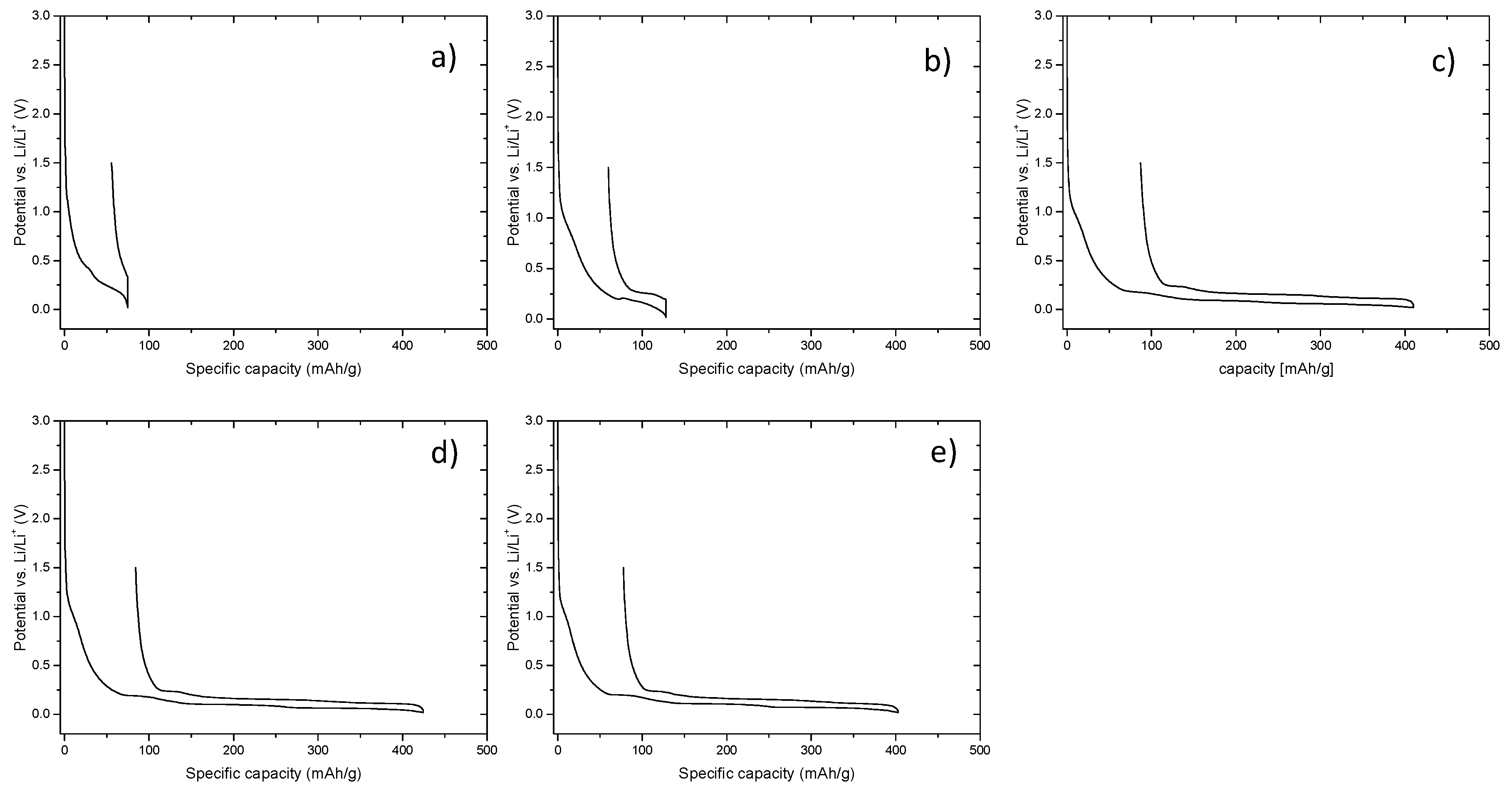
Figure 2.
Cycling profiles of graphite/Li cells containing 1 M LiPF6 in EMS with (a) 1% FEC; (b) 2% FEC; (c) 3% FEC and (d) 4% FEC, in the potential range from 0.02 to 1.5 V vs. Li/Li+.
Figure 2.
Cycling profiles of graphite/Li cells containing 1 M LiPF6 in EMS with (a) 1% FEC; (b) 2% FEC; (c) 3% FEC and (d) 4% FEC, in the potential range from 0.02 to 1.5 V vs. Li/Li+.
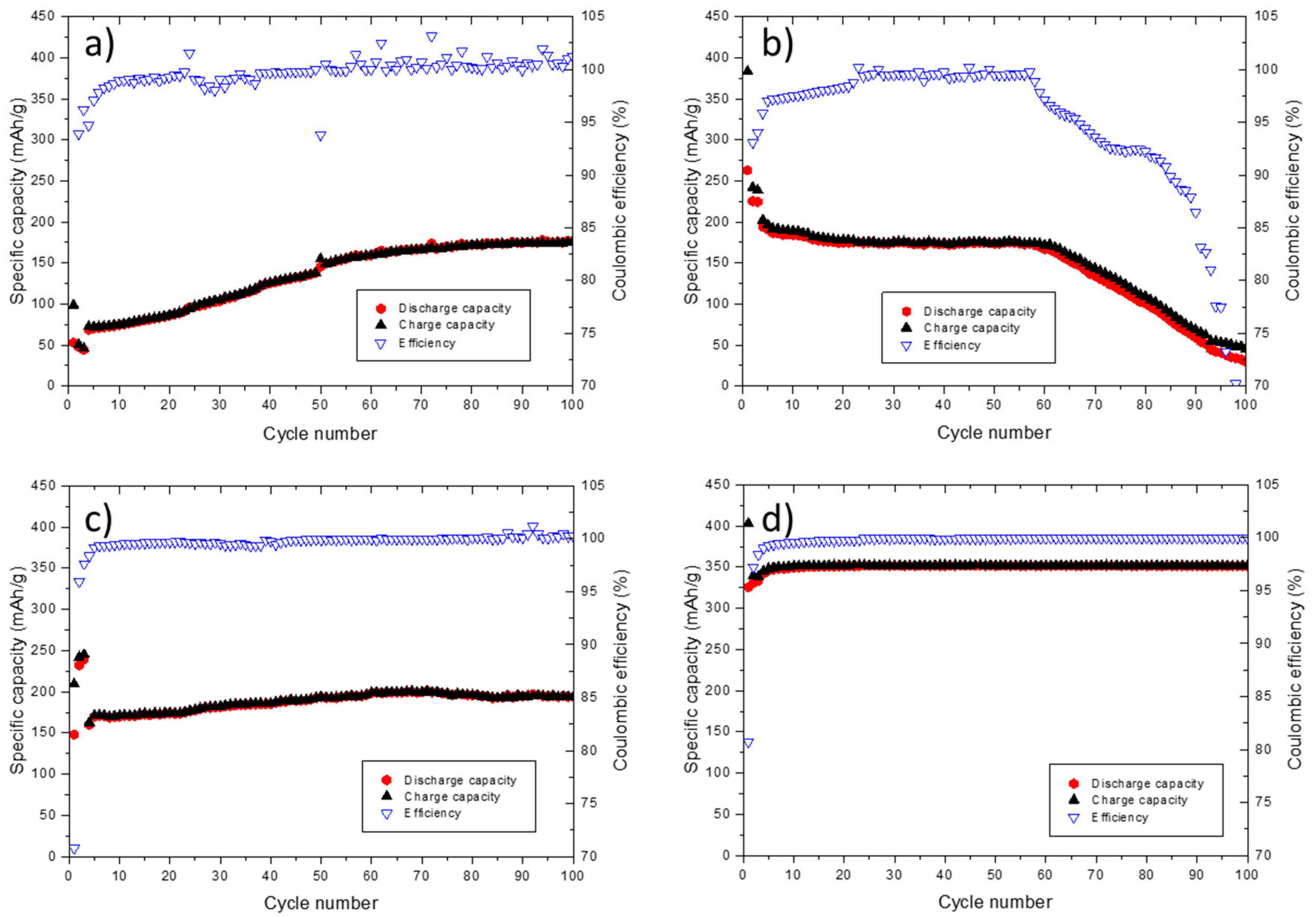
Figure 3.
Conductivity measurements of 1 M LiPF6 in EMS + 4% FEC, 1 M LiPF6 in EA + 4% FEC as well as 1 M LiPF6 in EMS:EA (1:1) + 4% FEC and 1 M LiPF6 in EC/DEC (3:7), in the temperature range from −40 °C to 60 °C.
Figure 3.
Conductivity measurements of 1 M LiPF6 in EMS + 4% FEC, 1 M LiPF6 in EA + 4% FEC as well as 1 M LiPF6 in EMS:EA (1:1) + 4% FEC and 1 M LiPF6 in EC/DEC (3:7), in the temperature range from −40 °C to 60 °C.

Figure 4.
First cycle potential profile of graphite/Li cell containing 1 M LiPF6 in EMS:EA (1:1) + 4% FEC electrolyte, in the potential range from 0.02 to 1.5 V vs. Li/Li+.
Figure 4.
First cycle potential profile of graphite/Li cell containing 1 M LiPF6 in EMS:EA (1:1) + 4% FEC electrolyte, in the potential range from 0.02 to 1.5 V vs. Li/Li+.

Figure 5.
XPS S 2p core spectra of graphite electrodes, after five charge/discharge cycles at 0.1C in graphite/Li cells with different amounts of FEC in the electrolyte (a) 1 M LiPF6 in EMS; (b) 1 M LiPF6 in EMS:EA (1:1); (c) 1 M LiPF6 in EMS:EA (1:1) with 1% FEC and (d) 1 M LiPF6 in EMS:EA (1:1) with 4% FEC; (e) pristine electrode. The electrodes where sputtered for 60 s, 120 s and 600 s, respectively.
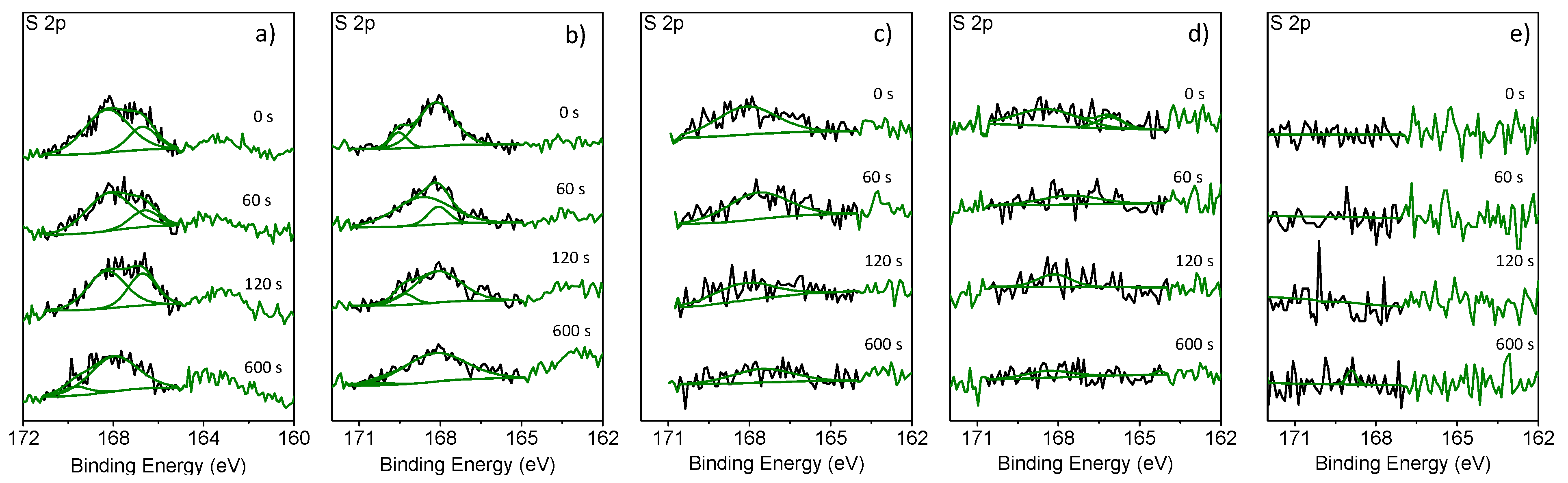
Figure 6.
Relative composition of sulfur content, organic and inorganic part of the SEI.
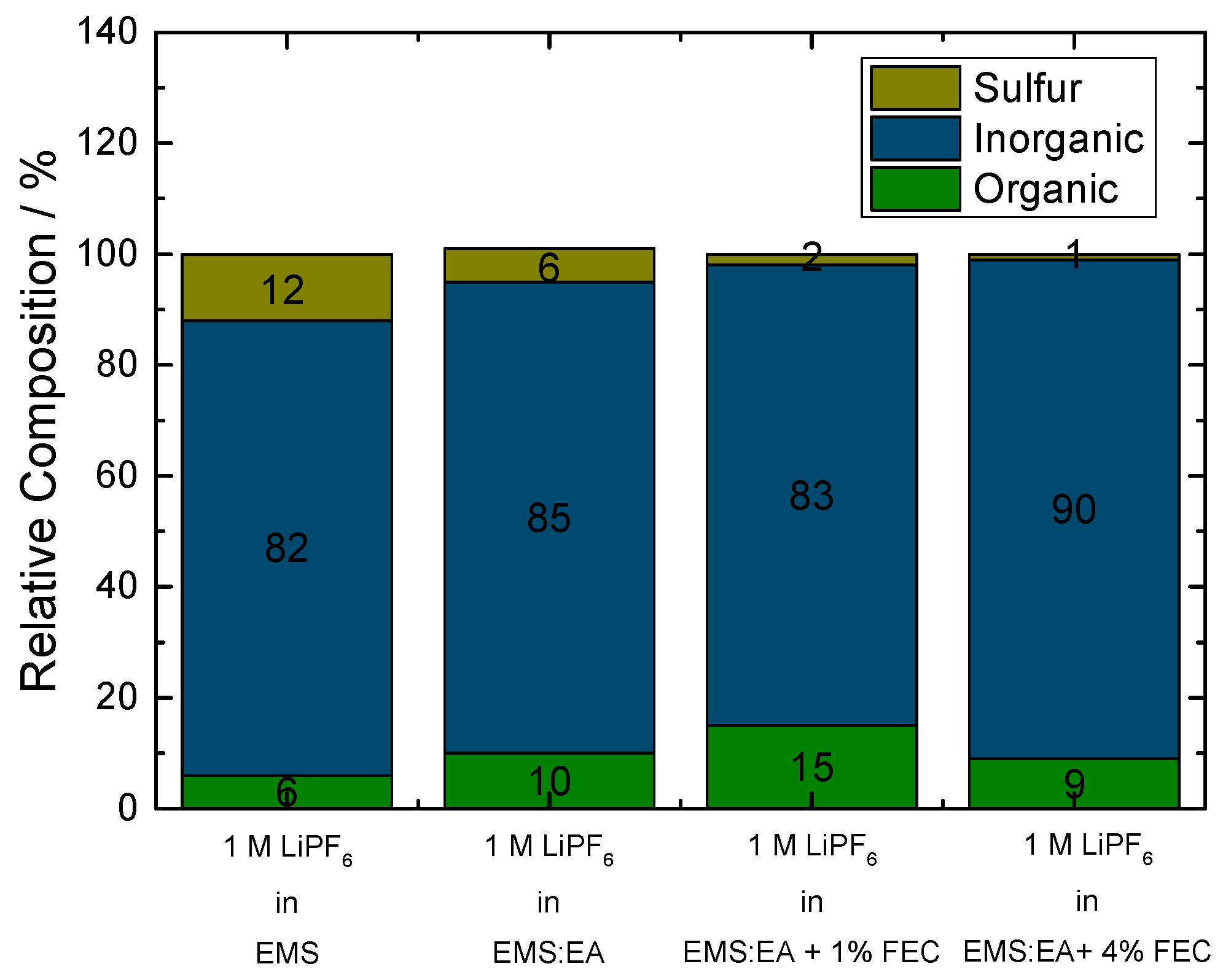
Figure 7.
Cycling profile of graphite/Li cell containing 1 M LiPF6 in EMS:EA (1:1) + 4% FEC electrolyte, in the potential range from 0.02 to 1.5 V vs. Li/Li+.
Figure 7.
Cycling profile of graphite/Li cell containing 1 M LiPF6 in EMS:EA (1:1) + 4% FEC electrolyte, in the potential range from 0.02 to 1.5 V vs. Li/Li+.
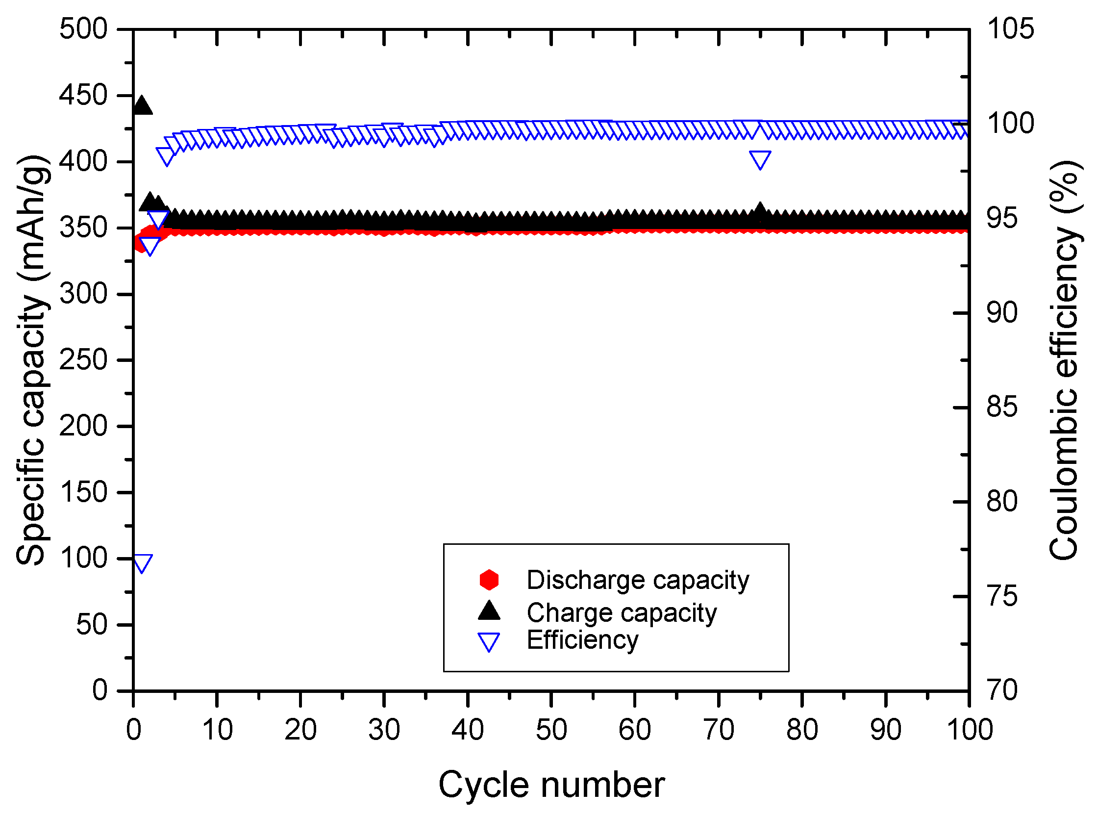
Figure 8.
Electrochemical stability window of 1 M LiPF6 in EMS, 1 M LiPF6 in EMS + 4% FEC and 1 M LiPF6 in EMS:EA + 4% FEC, respectively on LMO (WE) using lithium as both CE and RE, at a scan rate of 100 µV·s−1.
Figure 8.
Electrochemical stability window of 1 M LiPF6 in EMS, 1 M LiPF6 in EMS + 4% FEC and 1 M LiPF6 in EMS:EA + 4% FEC, respectively on LMO (WE) using lithium as both CE and RE, at a scan rate of 100 µV·s−1.
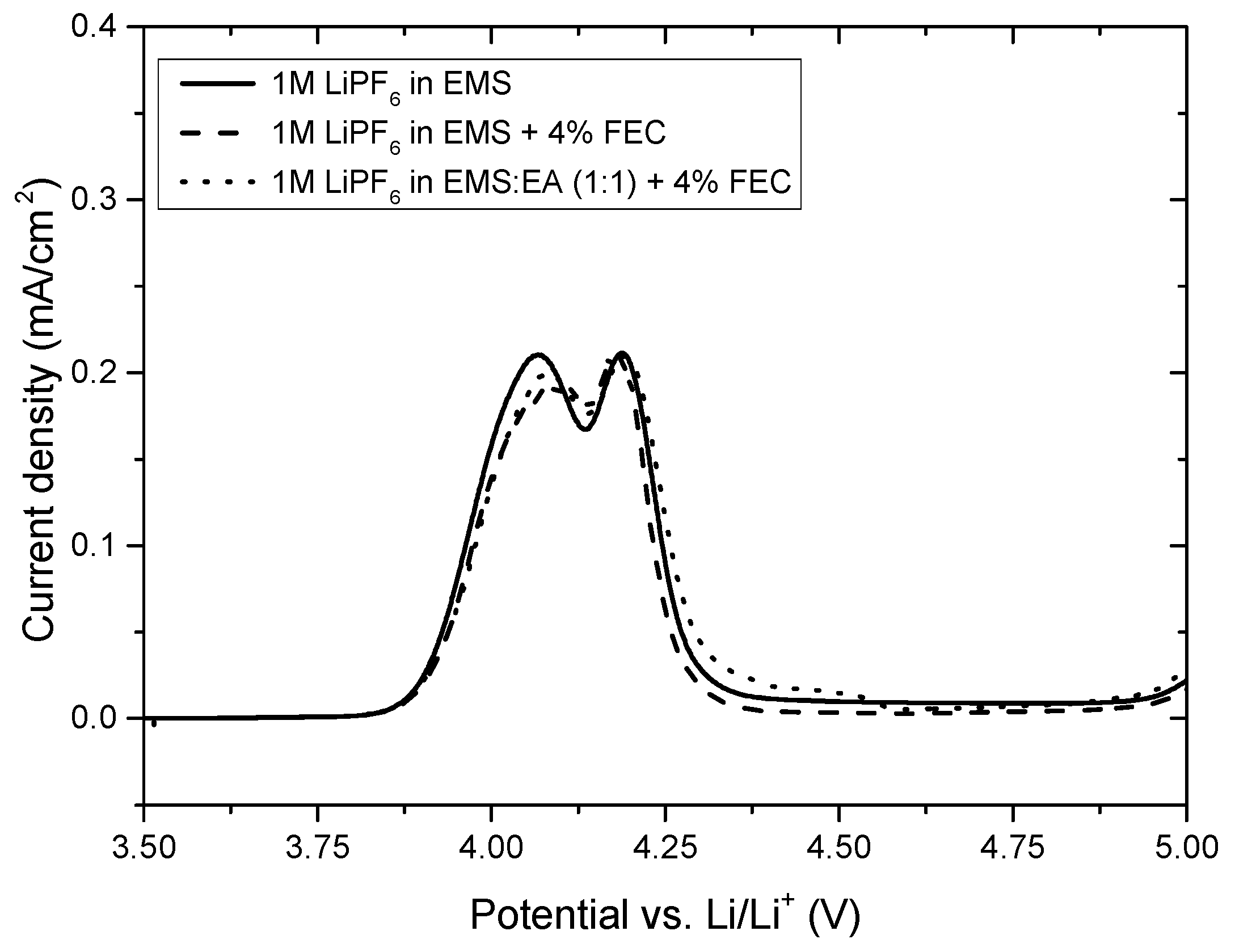
Figure 9.
Cycling profile of NMC/graphite cell containing 1 M LiPF6 in EMS:EA (1:1) + 4% FEC, in the voltage range from 3.0 and 4.3 V.
Figure 9.
Cycling profile of NMC/graphite cell containing 1 M LiPF6 in EMS:EA (1:1) + 4% FEC, in the voltage range from 3.0 and 4.3 V.
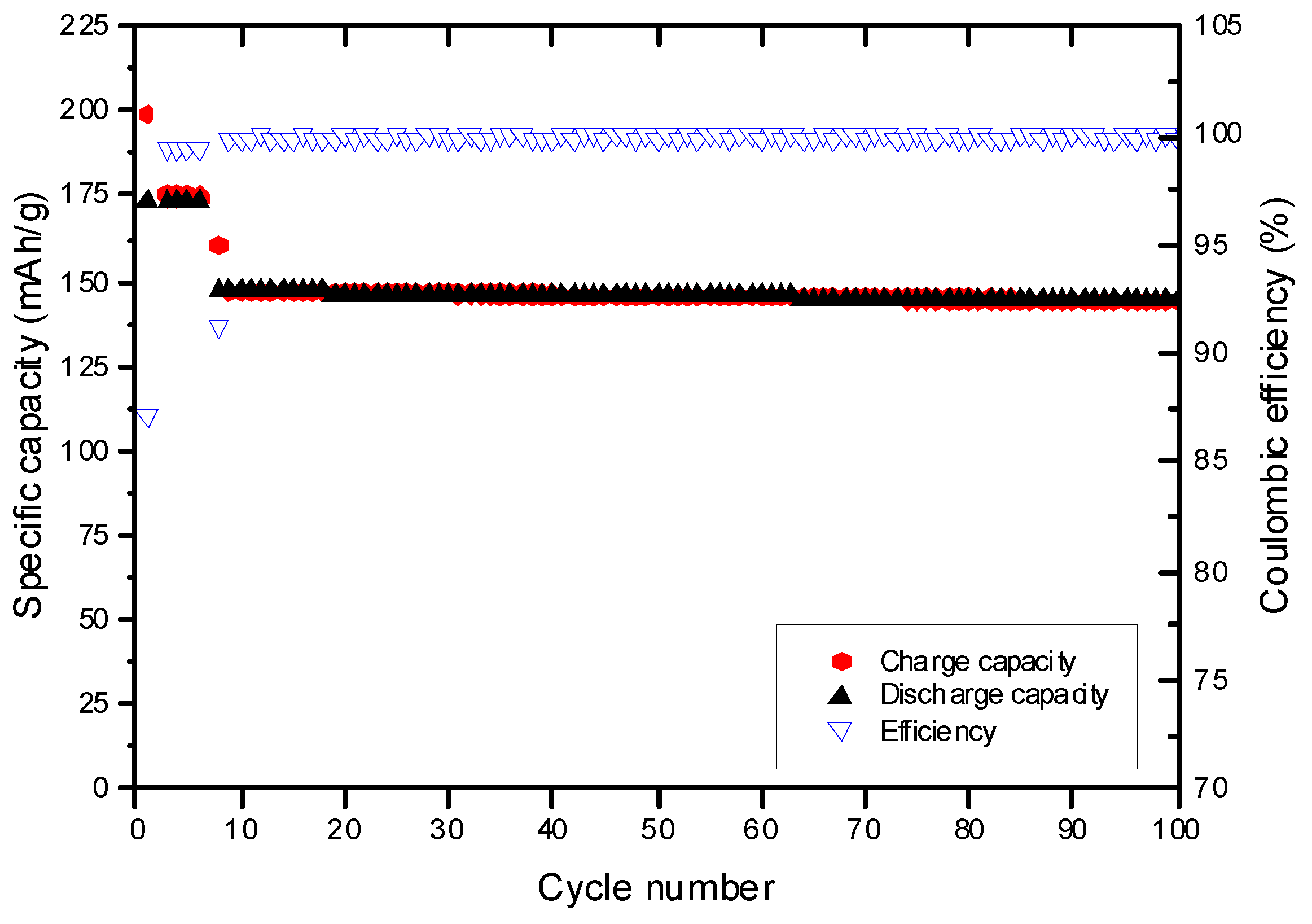
Figure 10.
Cycling profiles including charge/discharge rate test of NCM/graphite cells containing (a) 1 M LiPF6 in EMS:EA (1:1) with 4% FEC and (b) 1 M LiPF6 in EC:DEC (3:7) electrolytes in the voltage range between 3.0 and 4.3 V vs. Li/Li+.
Figure 10.
Cycling profiles including charge/discharge rate test of NCM/graphite cells containing (a) 1 M LiPF6 in EMS:EA (1:1) with 4% FEC and (b) 1 M LiPF6 in EC:DEC (3:7) electrolytes in the voltage range between 3.0 and 4.3 V vs. Li/Li+.

Figure 11.
Cycling profiles of NMC/graphite cells containing (a) 1 M LiPF6 in EtiPrSO2:EA (1:1) + 4% FEC and (b) 1 M LiPF6 in MeiPrSO2:EA (1:1) + 4% FEC, in the voltage range from 3.0 to 4.3 V.
Figure 11.
Cycling profiles of NMC/graphite cells containing (a) 1 M LiPF6 in EtiPrSO2:EA (1:1) + 4% FEC and (b) 1 M LiPF6 in MeiPrSO2:EA (1:1) + 4% FEC, in the voltage range from 3.0 to 4.3 V.

Table 1.
Coulombic efficiency values and measured potential drop between the charge and the discharge curve of the first cycle of the graphite/Li cells depicted in Figure 1.
Table 1.
Coulombic efficiency values and measured potential drop between the charge and the discharge curve of the first cycle of the graphite/Li cells depicted in Figure 1.
| Electrolyte Formulation | Coulombic Efficiency (%) | Potential Drop (V) |
|---|---|---|
| 1 M LiPF6 in EMS | 30.2 | 0.300 |
| 1 M LiPF6 in EMS with 1% FEC | 53.7 | 0.170 |
| 1 M LiPF6 in EMS with 2% FEC | 68.6 | 0.020 |
| 1 M LiPF6 in EMS with 3% FEC | 70.8 | 0.010 |
| 1 M LiPF6 in EMS with 4% FEC | 80.7 | 0.009 |
© 2017 by the authors. Licensee MDPI, Basel, Switzerland. This article is an open access article distributed under the terms and conditions of the Creative Commons Attribution (CC BY) license (http://creativecommons.org/licenses/by/4.0/).
Share and Cite
MDPI and ACS Style
Hilbig, P.; Ibing, L.; Wagner, R.; Winter, M.; Cekic-Laskovic, I. Ethyl Methyl Sulfone-Based Electrolytes for Lithium Ion Battery Applications. Energies 2017, 10, 1312. https://doi.org/10.3390/en10091312
AMA Style
Hilbig P, Ibing L, Wagner R, Winter M, Cekic-Laskovic I. Ethyl Methyl Sulfone-Based Electrolytes for Lithium Ion Battery Applications. Energies. 2017; 10(9):1312. https://doi.org/10.3390/en10091312
Chicago/Turabian StyleHilbig, Peter, Lukas Ibing, Ralf Wagner, Martin Winter, and Isidora Cekic-Laskovic. 2017. "Ethyl Methyl Sulfone-Based Electrolytes for Lithium Ion Battery Applications" Energies 10, no. 9: 1312. https://doi.org/10.3390/en10091312
Note that from the first issue of 2016, this journal uses article numbers instead of page numbers. See further details here.