A Torque Error Compensation Algorithm for Surface Mounted Permanent Magnet Synchronous Machines with Respect to Magnet Temperature Variations †


1
Department of Electrical Engineering, Kyungnam University, Changwon-si 51767, Korea
2
Department of Electrical Engineering, Chonbuk National University, Jeonju-si 54896, Korea
*
Author to whom correspondence should be addressed.
†
Presented at Sustainable Places 2018 (SP 2018), Aix-les Bains, France, 27–29 June 2018.
Energies 2017, 10(9), 1365; https://doi.org/10.3390/en10091365
Submission received: 1 May 2018
/
Revised: 1 August 2018
/
Accepted: 1 August 2018
/
Published: 24 August 2018
(This article belongs to the Special Issue Emerging Power Electronics Technologies for Power Systems and Machine Drives)
Abstract
:This paper presents a torque error compensation algorithm for a surface mounted permanent magnet synchronous machine (SPMSM) through real time permanent magnet (PM) flux linkage estimation at various temperature conditions from medium to rated speed. As known, the PM flux linkage in SPMSMs varies with the thermal conditions. Since a maximum torque per ampere look up table, a control method used for copper loss minimization, is developed based on estimated PM flux linkage, variation of PM flux linkage results in undesired torque development of SPMSM drives. In this paper, PM flux linkage is estimated through a stator flux linkage observer and the torque error is compensated in real time using the estimated PM flux linkage. In this paper, the proposed torque error compensation algorithm is verified in simulation and experiment.
1. Introduction
Permanent magnet synchronous machines (PMSMs) have been widely used in various applications is sectors such as the aerospace and automotive industry due to their high power density and efficiency [1,2,3]. PMSMs can be divided into two types depending on their rotor structure, which are surface mounted PMSMs (SPMSMs) and interior PMSMs (IPMSMs). Since the operation speed range of SPMSMs is narrower than that of IPMSMs due to their rotor structure characteristics, flux weakening control and operation are rarely typical for SPMSMs like for IPMSMs. For much of the research about flux weakening of SPMSMs, design approaches to extend the flux weakening region have been presented [4,5,6,7] rather than control aspects. For that reasons, an IPMSM is typically preferred for those applications requiring a wider speed operation range such as automotive applications. Compared to IPMSMs, SPMSMs are simpler to control and manufacture, therefore, SPMSMs are preferred for servo motor and home appliance applications.
While PMSMs have advantages, as stated above, the parameters of PMSMs are dependent on external conditions such as temperature and operating conditions and this affects the torque response and efficiency of PMSM drives [8]. Among them, the influence of temperature causes problems directly related to torque production [9,10]. For efficient operation of PMSMs, Maximum torque per ampere (MTPA) is one of the widely used control algorithms. An MTPA trajectory is normally developed as a look up table (LUT) and is developed using machine parameters, for example, d and q axis inductance and PM flux linkage. When torque command is given as an input to an MTPA LUT, d and q axis current vector command are selected as output signals from the MTPA LUT. When machine parameters are changed due to external conditions, an incorrect current vector command for command torque is selected from the MTPA LUT and this results in undesired torque development in PMSMs [11,12]. Especially, the effect of PM flux linkage is dominant for torque development of PMSMs and the PM flux linkage decreases due to demagnetization as the magnet temperature increases. Many researchers have proposed solutions for torque error compensation with respect to temperature variation. Online parameter identification methods can be applied to maintain MTPA performance, but the methods are typically complicated to implement [13,14]. In [15], an algorithm using MTPA LUTs and a flux observer based on a voltage model was proposed, but the algorithm is expected to have a limited performance at low speed due to the voltage model-based flux observer used. Also, PM flux linkage can be simply estimated through back-emf estimation method. However, the back-emf method is affected by not only the dead time at low speed but also machine parameter variations. A perturbation searching method was presented and MTPA can then be achieved regardless of parameter variation [16,17,18,19], but the dynamic performance is degraded because the perturbation search takes time. High frequency signal injection methods are proposed in [19,20,21]. Though MTPA operation is achieved regardless of parameter variations applying high frequency signal injection methods, not only the injected current signal results in additional loss in an inverter and a motor but also it results in undesired influence on the motor operation. Recent research shows PM temperature estimation for PMSMs and variable flux PMSMs but torque error compensation for PMSMs was not addressed in the algorithms [22,23,24].
In this paper, PM flux linkage is estimated via a Gopinath style stator flux linkage observer and the estimated PM flux linkage is used for torque error compensation for SPMSMs under various temperature conditions in real time. In the following sections, a characteristic of the stator flux linkage observer is described and analyzed. The proposed torque error compensation algorithm is presented to improve torque development accuracy under various temperature conditions. Since flux weakening control of a SPMSM drive is not as typical as an IPMSM drives, the test SPMSM drive is controlled up to rated speed in this paper. The proposed real time torque error compensation algorithm is verified through MATLAB/Simulink simulation and experimental results under various temperature conditions in this paper.
2. Gopinath Style Stator Flux Linkage Observer
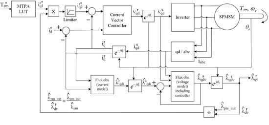
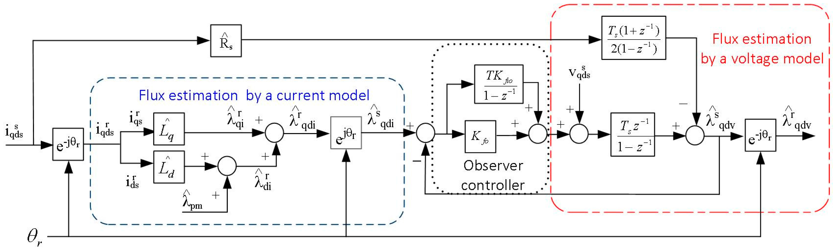
A Gopinath style stator flux linkage observer has been presented for induction motor drives [25,26,27] and PMSM drives [28,29]. The stator flux linkage observer for PMSM drives shown in Figure 1 is used for implementation of the torque error compensation algorithm.
As shown in Figure 1, stator flux linkage of a SPMSM is estimated based on a current model and a voltage model. In this paper, subscript q and d are q and d axis. Superscripts s and r are the stator and rotor reference frames of a PMSM, respectively. Also, * stands for command signal and ^ represents estimated value. For example, and are the estimated stator flux linkage in the rotor reference frame using a current model and a voltage model of a stator flux linkage observer, respectively.
At low speeds, voltage is not the proper signal to be used for stator flux linkage estimation because dead time and noise signals distort the voltage. As a result, flux estimation using the distorted voltage yields inaccurate stator flux linkage estimations. Therefore, stator flux linkage is estimated via a current model at low speeds as given by (1) and (2):
However, flux estimation using a current based model is an open loop estimation and sensitive to parameter variations as seen from Equations (1), (2) and Figure 1. As speed increases, the effect of dead time and noise signal can be negligible due to high back-emf voltage of a SPMSM. Then, stator flux linkage can be estimated using a voltage model, which is developed based on Equation (3):
Estimation of stator flux linkage using a voltage model is preferred compared to a current model because it is independent from parameter variation as shown by Equation (3). Voltage drop across a stator resistor is negligible at high speed operation. Determination of a crossover point between a current model and a voltage model is one of important issues in design of the stator flux linkage observer. The crossover point is determined by a bandwidth of a controller of the stator flux linkage observer located between a current model and a voltage. There is no certain answer for optimal crossover frequency of a stator flux linkage model. Considering applications and operating conditions, optimal crossover frequency of a stator flux linkage observer should be determined. A transfer function of Gopinath-style observer can be derived in continuous time domain as (4) in [24]. The Kfo and the Kfio are the proportional and integral controller gains of the Gopinath-style stator flux-linkage observer respectively in Figure 1 and Lqd is the mutual inductance of q to d showing cross-saturation characteristic of PMSMs:
where:
In Equation (4), ωr and θr are the speed and position of the rotor of PMSMs, respectively.
3. Proposed Torque Error Compensation Algorithm
As known, copper loss of a motor is proportional to the square of the current magnitude. Therefore, a use of minimum current magnitude for a specific torque development is applied for PMSM control for efficient operation. The torque equation of PMSMs is shown in Equation (5). In case of SPMSM, Ld ≅ Lq due to its rotor structure and Equation (5) can be simplified as Equation (6):
In Equation (5), Tem is the electric magnetic air-gap torque and λpm is the permanent magnet flux linkage of a permanent magnet of a PMSM rotor and P stands for a number of poles of PMSMs. As shown in Equation (6), only the q-axis current is used for torque development and the d-axis current of a SPMSM is controlled as zero for maximum torque production utilizing a minimum current magnitude. The torque production maximization method is defined as an MTPA. As shown in Equation (6), estimated PM flux linkage is a critical variable for an MTPA LUT development. When the PM flux linkage varies due to magnet temperature variation, the variation of PM flux linkage is not reflected to the developed MTPA LUT and this results in undesired q-axis current command selection from the MTPA LUT and eventually in undesired torque development. Figure 2 shows the MTPA trajectory of SPMSM.
In this paper, PM flux linkage is estimated in real time using an estimated stator flux linkage from the stator flux linkage observer in Figure 1. The estimated stator flux linkage vector for a voltage model can be divided into the d and q axis. The d-axis stator flux linkage can be presented with respect to current and machine parameters as in Equation (7):
In this paper, the considered operation speed range is up to rated speed of a SPMSM because flux weakening operation of SPMSMs is not as usual as in IPMSMs. Below a rated speed, d-axis current is controlled as zero current for MTPA purpose in a SPMSM drive. Referring to Equation (7), the estimated PM flux linkage can be considered as the estimated d-axis stator flux linkage regardless d-axis inductance variation if d-axis current is controlled as zero current below a rated speed. Therefore, a torque error correction coefficient Kcr can be calculated as in Equation (8) and it is applied for the output of an MTPA LUT. In Equation (8), is the initial PM flux linkage used for an MTPA LUT development and is the PM flux linkage estimated by a stator flux linkage observer:
4. Simulation Results
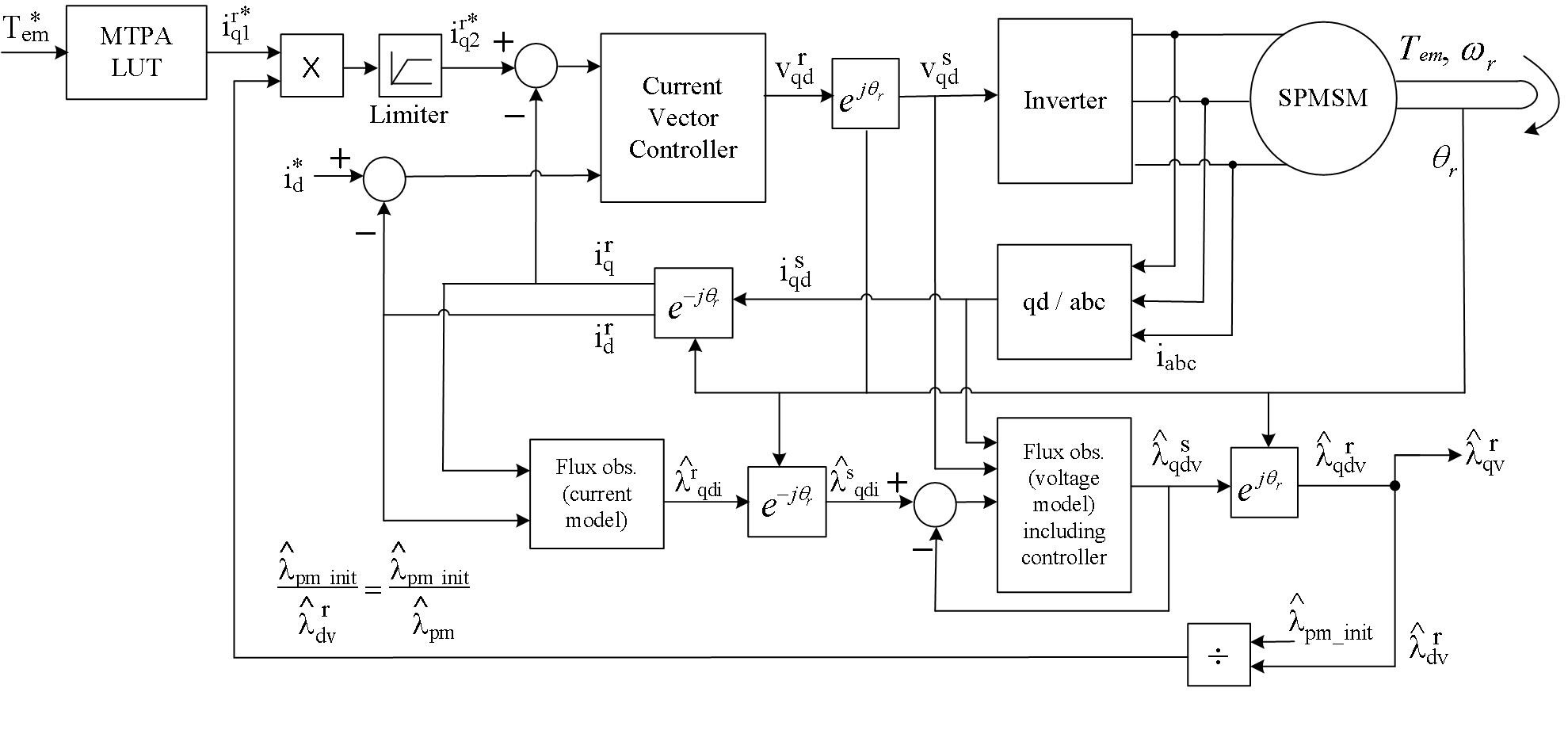
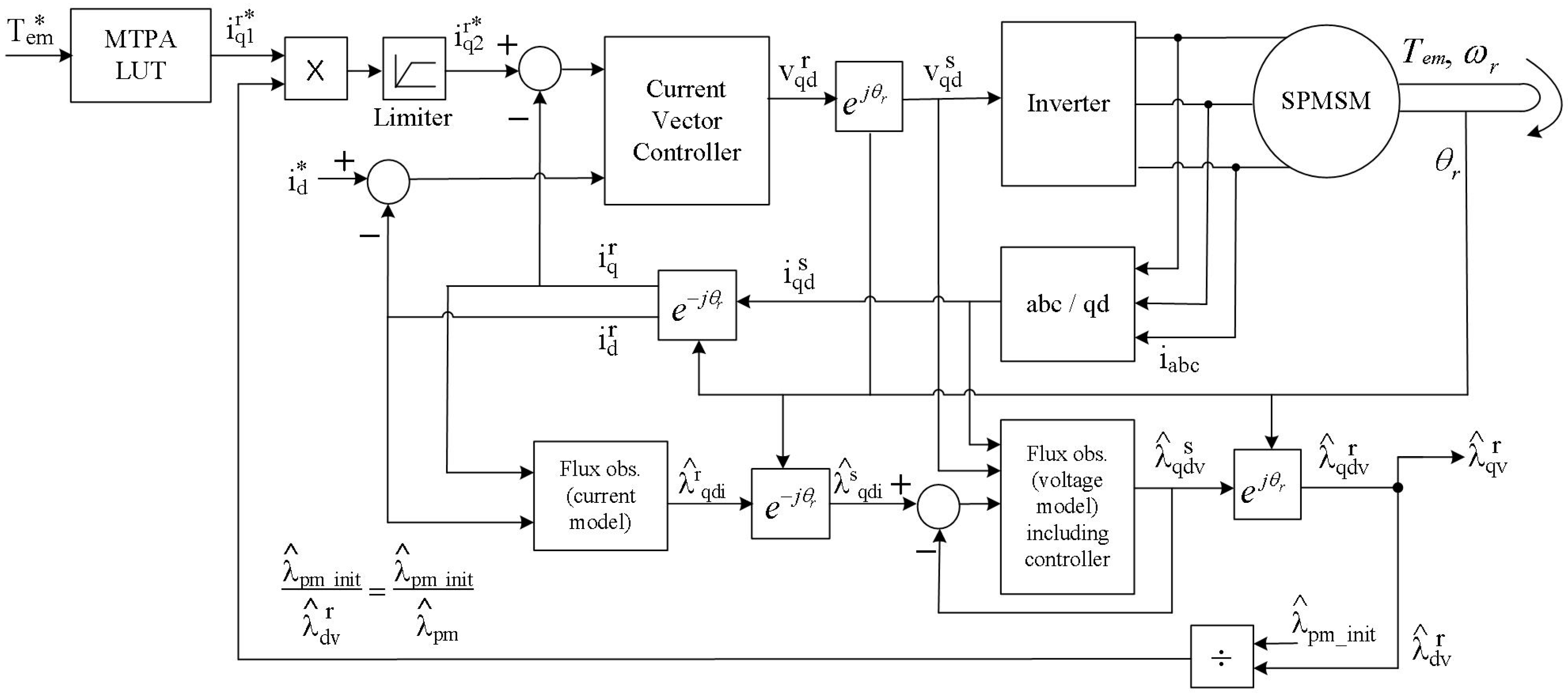
The proposed torque error compensation control system is implemented and verified through MATLAB/Simulink simulation. In simulation, a 100 µs time step is applied and Rosenbrock is used as a solver. Also, a frequency response of a stator flux linkage observer with respect to parameter variations is evaluated in the simulation. A block diagram for the proposed torque error compensation control system for SPMSM drives is shown in Figure 3. As seen in Figure 3, the proposed torque error compensation algorithm and a stator flux linkage observer are integrated into a typical complex vector current control system. A q-axis current command, , is corrected using the estimated PM flux linkage from the stator flux linkage observer. The corrected q-axis current command, , is constrained by a limiter not to exceed the maximum current of a motor drive system.
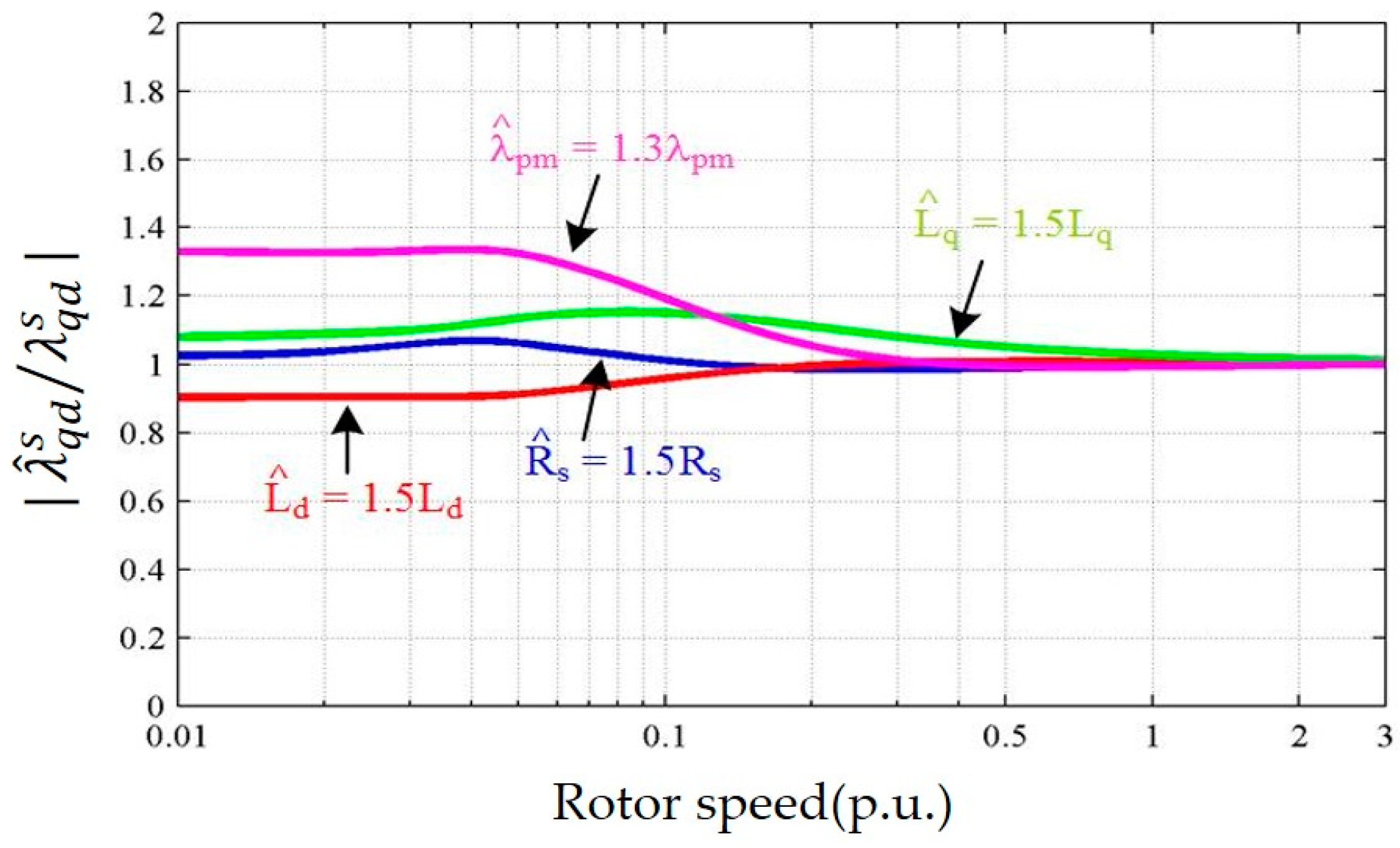
Figure 4 shows simulation results of a frequency response of a Gopinath style stator flux linkage observer at a wide operating speed range while parameters of SPMSM are varied intentionally.
In Figure 4, the bandwidth of the stator flux linkage observer controller, which is a crossover frequency between a current model and a voltage model is set to be 0.1 p.u of the rated speed of the test SPMSM. The simulation result shows that accuracy of estimated stator flux linkage over a wide operating speed range. For example, is close to 1 when the stator flux linkage is estimated accurately. In Figure 4, Rs, λpm, Ld and Lq are intentionally detuned from 30~50% to simulate SPMSM parameter variations. Referring to the characteristics of the stator flux linkage, it is expected to see inaccurate stator flux estimation while a SPMSM operates below the crossover frequency. Then, estimation of the stator flux linkage becomes accurate when the SPMSM operates beyond the crossover frequency of the stator flux linkage observer.
As shown in Figure 4, it is verified that the accuracy of stator flux linkage estimation is affected by the parameter variation at low speeds while the accuracy of stator flux linkage estimation becomes robust to parameter variation beyond a crossover frequency of the stator flux linkage observer controller. Figure 4 shows that the estimated stator flux linkage at high speeds is an accurate value. Therefore, the estimated stator flux linkage can be used for development of the proposed torque error compensation algorithm.
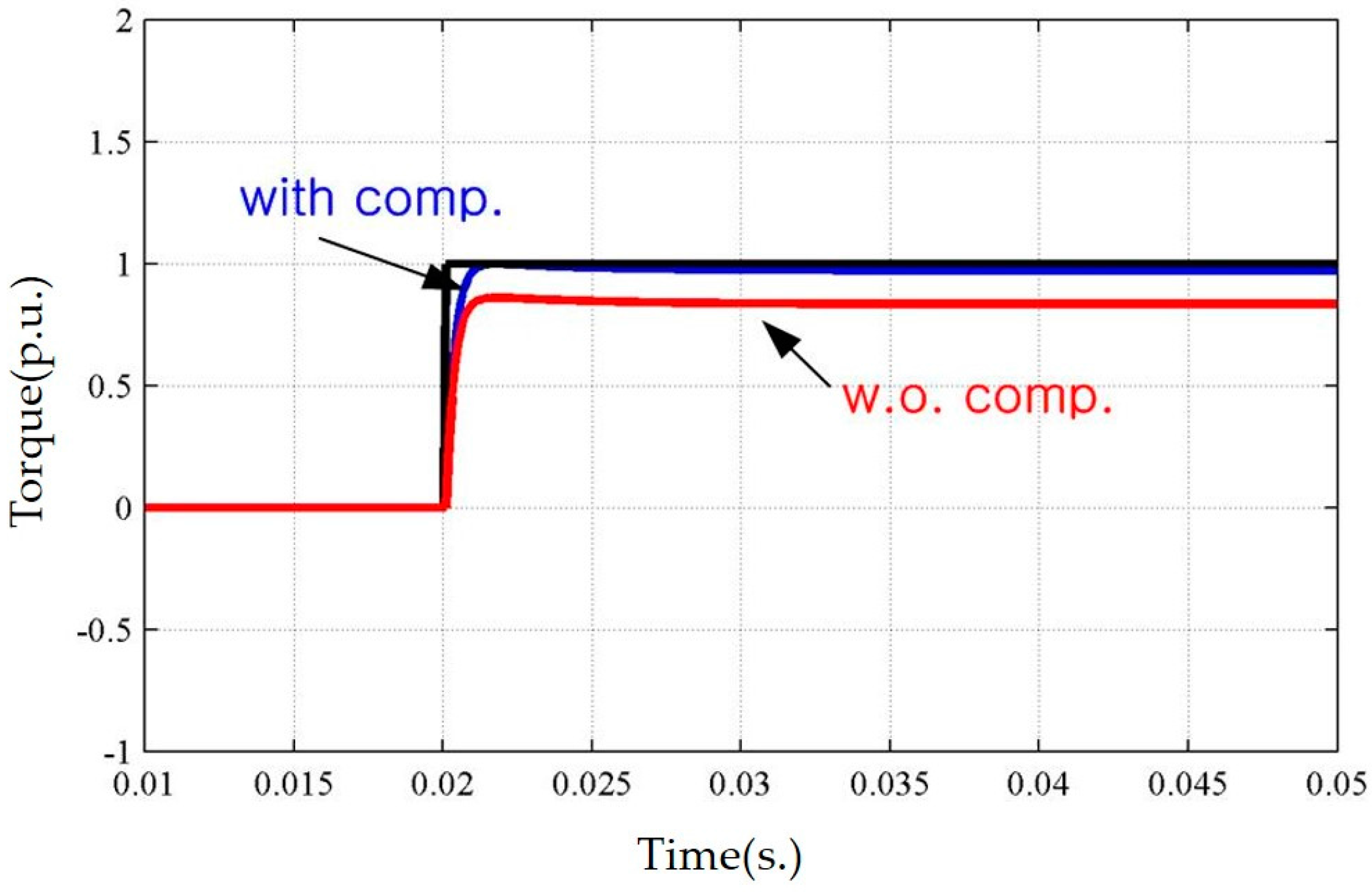
Among the PMSM parameters in Figure 4, PM flux linkage and stator resistance are affected by temperature variation. Since stator resistance variation is ignorable based on the results in Figure 4, PM flux linkage variation to stator flux linkage estimation is considered in this paper. To verify the proposed algorithm, 20% of error is applied to a PM flux linkage in a simulation model intentionally. Operating speed is set to be 300 rad/s, which is higher than a bandwidth of a stator flux linkage observer controller to utilize an estimated stator flux linkage from a voltage model of the stator flux linkage observer. The simulation result for a step torque command is shown in Figure 5.
From the simulation result in Figure 5, it is verified that torque error due to the PM flux linkage variation can be corrected when the proposed torque error compensation algorithm is applied. It should be noted that performance of the proposed algorithm is degraded when operating speed is below the stator flux linkage observer due to speed dependency of the stator flux linkage observer.
5. Experimental Results
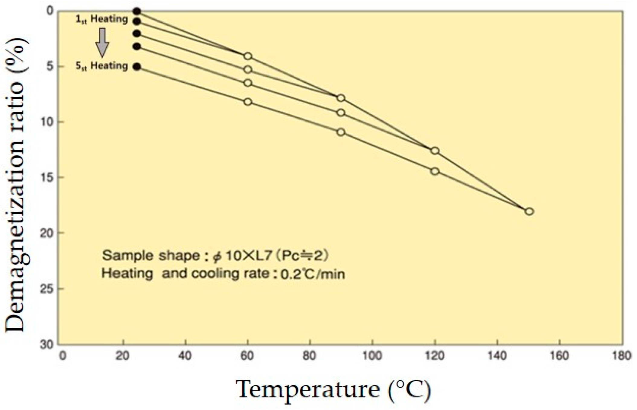
The proposed torque error compensation algorithm is implemented and verified through experiment. First of all, characteristics of the permanent magnet (NP-8R 6kOe, Daido Electronics, Nakatsugawa, Japan) in the test SPMSM are analyzed through its datasheet and experiment. Figure 5 shows demagnetization characteristic of the PM of the test motor provided in the datasheet. As shown in Figure 6, the PM in the test SPMSM is demagnetized as temperature increases and it results in decrease of the magnetic flux linkage.
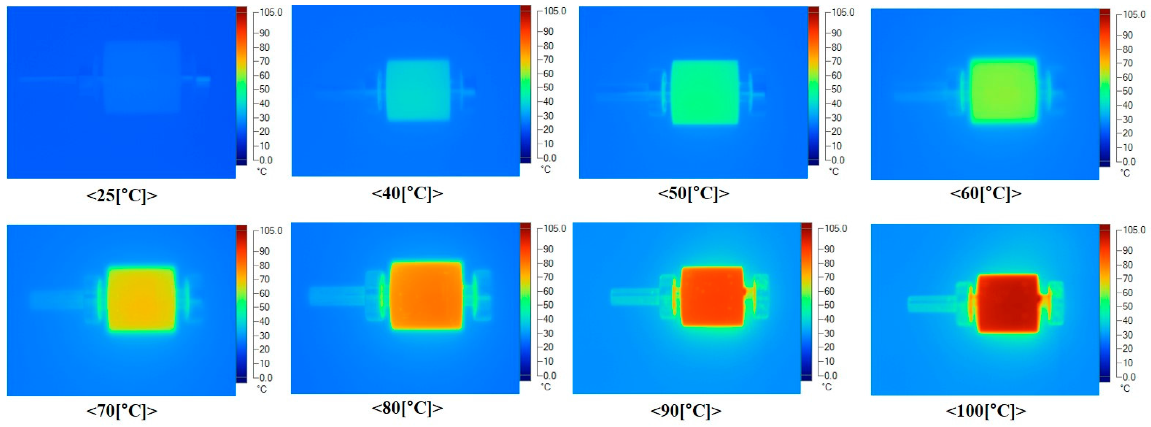
To verify demagnetization characteristic of the permanent magnet flux linkage with respect to temperature variation experimentally, permanent magnet is intentionally heated with a heating gun. The permanent magnet temperature is changed from 25 to 100 °C and the temperature distribution of the test motor is measured by a TI 55 thermal imaging camera (FLUKE, Everett, WA, USA). Figure 7 shows the experimental measurement of the temperature change of the permanent magnet.
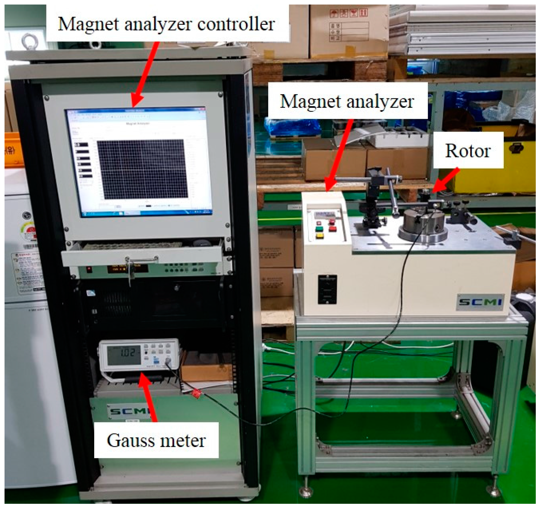
Figure 8 shows an experimental test set up for a gauss meter used for measurement of the magnetic flux of the permanent magnet at each temperature. In room temperature, the initial permanent magnet flux linkage is measured to be 1273 G. By repeating the experiment in Figure 7, it is observed that the permanent magnet is demagnetized even it is cooled down to 25 °C. The experiment is implemented after permanent magnet is fully demagnetized. During the experiment temperature is increased from 25 to 100 °C. The overall permanent magnet flux linkage of the test SPMSM with respect to temperature variation is shown in Figure 9. The experimental results closely match the demagnetization ratio trajectory shown in Figure 6.
Electrical and mechanical parameters of the test SPMSM are summarized in Table 1. Figure 10 shows the experimental test set up. The load motor is operated in a speed control mode and mechanically coupled to the SPMSM test machine. The proposed torque error compensation algorithm is implemented in the motor drive with 10 kHz of PWM sampling frequency. The rotor temperature is measured by inserting a non-contact thermometer inside the SPMSM using a Fluke multimeter.
During the experiment, the transient and steady state torque responses of the SPMSM drive are tested at room temperature (25 °C) and 100 °C. Speed of the load motor is controlled to be 65 rad/s and 310 rad/s for low and high speed operations, respectively. The criteria of the low and high speed operating points is determined by the bandwidth of the stator flux linkage observer used in the proposed algorithm. From the characteristic of the stator flux linkage observer in Figure 4, it can be expected that the steady state torque error occurs at low speed and the error would be compensated at high speeds.
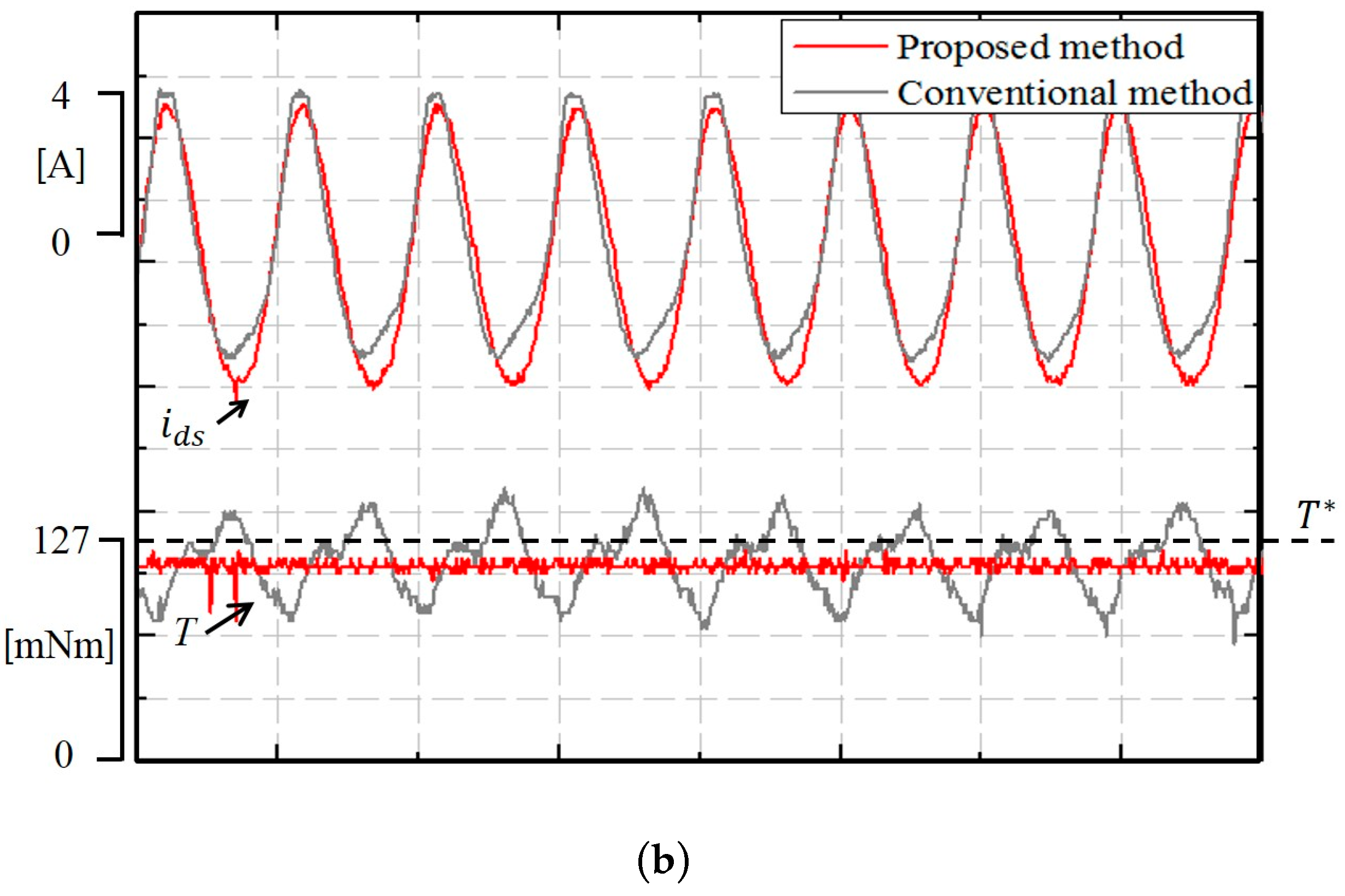
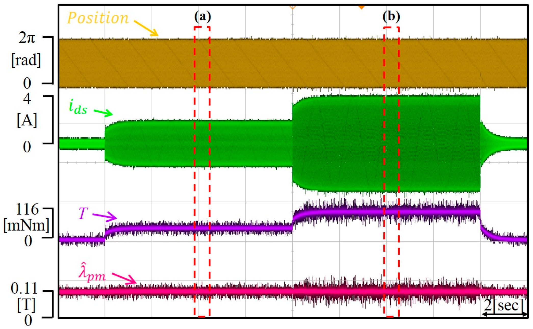
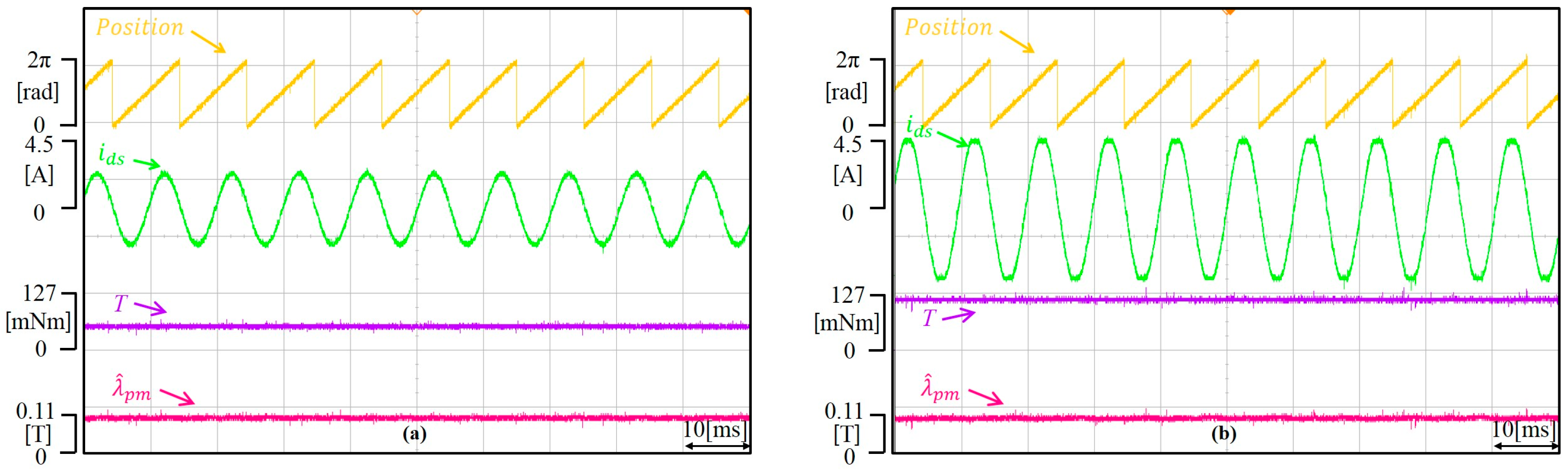
First of all, the proposed torque error compensation method and the conventional method presented in [10] is implemented at low speed in experiment and the results are shown in Figure 11. As stated in the Introduction section, stator flux linkage is estimated solely by a voltage model in [10] regardless of operating speed. Therefore, the estimated stator flux linkage at low speed is affected by the voltage distortion caused by dead time and noise. Figure 11 shows two operating temperature cases, which are at 25 °C and 100 °C at low speeds. Figure 11a shows that developed torque using the proposed method is less distorted compared to the conventional method because the stator flux linkage used for torque error compensation is estimated based on a current model, which is not affected by dead time and noise. Figure 11b shows the experimental result at 100 °C at low speeds using both methods. Torque response using the proposed method still shows improved torque response with less distortion comparing to the conventional method. However, steady state torque error caused by permanent magnet temperature variation is not compensated. The limitation of the proposed method should be noticed from Figure 11b. At high speed, the proposed torque compensation algorithm also estimates the stator flux linkage using a voltage model as the method in [12]. Therefore, the comparison with the algorithm in [12] is only implemented for low speed operation.
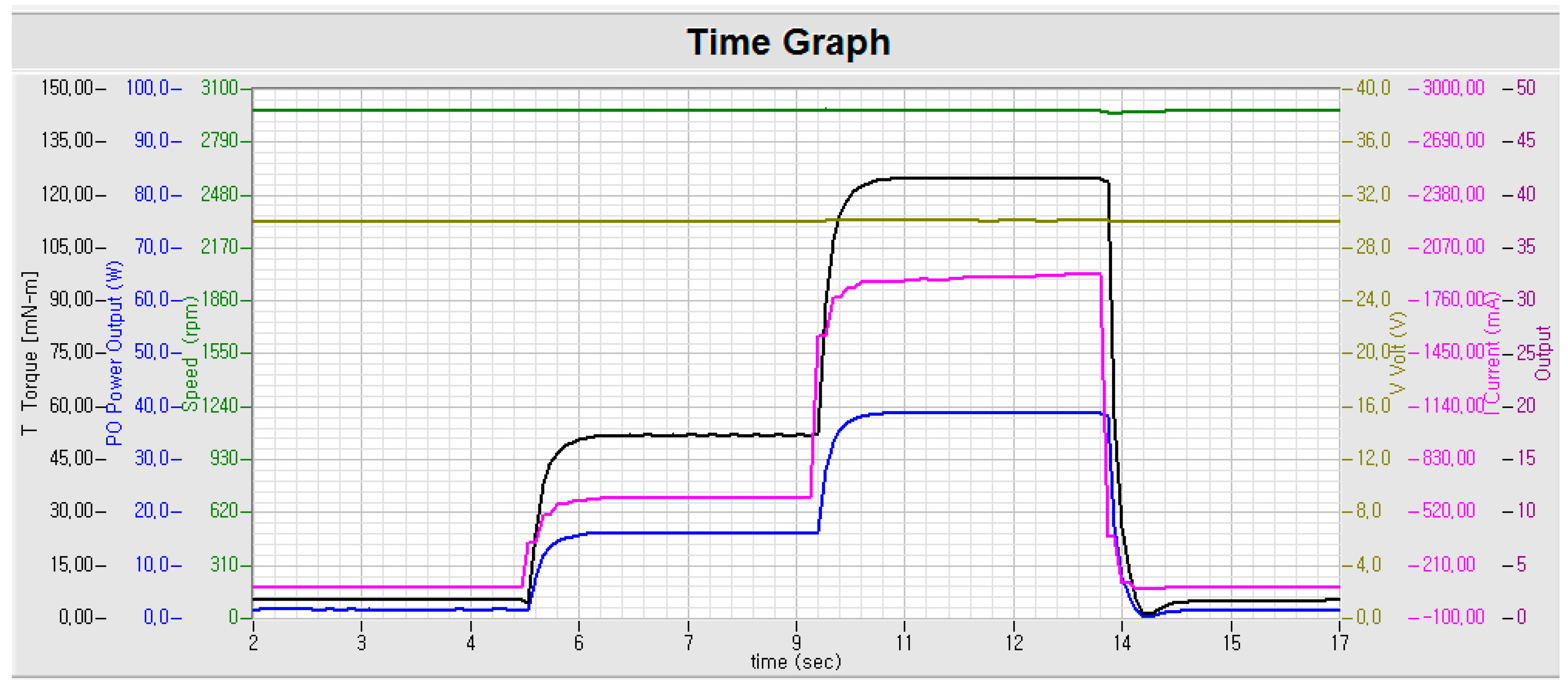
For the transient torque response test, a step torque command is applied to the test SPMSM drive. During the test, the torque is calculated using the estimated SPMSM parameters. First of all, two different levels of torque are applied to the test SPMSM while the speed of load motor is controlled to be 620 rad/s at 25 °C without applying the proposed algorithm. Figure 12 shows the experimental results of transient torque response at the given operating condition and it can be seen that the torque of the test SPMSM drive is controlled adequately. Figure 13a,b show the steady state responses when torque commands of 50 mNm and 127 mNm are applied at a load speed of 620 rad/s. Torque is controlled accurately at the given operating conditions and it is also shown that the permanent magnet flux is accurately estimated regardless of load change. Figure 13 shows the output waveform from the motor performance tester. As shown in Figure 13a, 0.52 A of current is applied for 50 mNm of torque command and 1.8 A of current is applied for 127 mNm of torque command. From Figure 12, Figure 13 and Figure 14, it is seen that torque of SPMSM is accurately controlled without the proposed algorithm at the room temperature, 25 °C.
Next, the test SPMSM is heated by a heat gun intentionally until the rotor temperature of the SPMSM reaches 100 °C. At high temperature, the permanent magnet is demagnetized and this results in permanent flux linkage reduction. Then, the developed torque is expected to be reduced when the same magnitude of current is applied. The test procedure is repeated as in the previous experiment and the experimental results at 100 °C are shown in Figure 15, Figure 16 and Figure 17.
Figure 16 shows the steady state result when torque commands of 50 mNm and 127 mNm are applied at a speed load of 620 rad/s and the output torque is not reached at the commanded torque for both cases without applying the proposed algorithm. When the temperature of the permanent magnet is increased to 100 °C, the magnetic flux linkage is decreased due to demagnetization. Without compensating for the permanent flux linkage variation, the MTPA trajectory developed based on the information at room temperature results in undesired torque development. The results of the motor performance tester in Figure 17 show that the developed torque is smaller than the commanded torque while the current magnitude applied is same as the current magnitude applied at the room temperature.
The proposed torque compensation algorithm is applied when the permanent magnet temperature increased to 100 °C and the experimental results are shown in Figure 18, Figure 19 and Figure 20. Figure 18 shows transient torque responses when torque changes from 0 to 50 mNm and 50 mNm to 127 mNm. From Figure 18, it is verified that the proposed algorithm does not affect transient performance of a motor drive. In Figure 19a,b the steady state torque response when 50 mNm and 127 mNm of torque are commanded, respectively, is shown. As shown in Figure 19, the output torque satisfies the target command torque when the proposed torque error compensation algorithm is applied although the temperature of the permanent magnet is increased to 100 °C. Also, it is observed that the commanded current magnitude at 100 °C is increased compared to the commanded current magnitude at 25 °C. Since the variation of permanent magnet flux linkage due to the high temperature can be estimated by the proposed torque error compensation algorithm, the commanded current magnitude to the SPMSM is corrected to satisfy the command torque.
6. Conclusions
In this paper, the output torque development error due to demagnetization of the permanent magnet of a SPMSM with respect to temperature variation is analyzed and an algorithm for compensating the torque at various temperature conditions is proposed. The proposed torque error compensation algorithm is verified by simulation and experimental tests. Permanent magnet flux linkage of a SPMSM is estimated through a stator flux linkage observer and the torque development error due to temperature variation is compensated using the estimated permanent magnet flux linkage in real time. Though the proposed torque compensation algorithm has a constrained performance at low speed (below a bandwidth of the stator flux linkage observer) due to the inherent characteristics of the Gopinath style stator flux linkage observer, it shows improved torque development performance (about 10%) compared to the conventional method. Also, it is a meaningful algorithm in the aspect of simple and real time implementation which is not using any external hardware and off-line experimental measurements.
Acknowledgments
This research was supported by Korea Electric Power Corporation through Korea Electrical Engineering & Science Research Institute [grant number: R17XA05-7]. This research was supported by Base Science Research Program through the National Research Foundation of Korea (NRF) funded by the Ministry of Education (2017R1D1A1B03031979).
Author Contributions
Chang-Seok Park implemented experiment. Jae Suk Lee proposed the algorithm and implemented simulation.
Conflicts of Interest
The authors declare no conflict of interest.
References
- Xuan, W.; Hui, W.; Shoudao, H.; Keyuan, H.; Li, W. Sensorless Speed Control with Initial Rotor Position Estimation for Surface Mounted Permanent Magnet Synchronous Motor Drive in Electric Vehicles. Energies 2015, 8, 11030–11046. [Google Scholar]
- Chu, L.; Jia, Y.; Chen, D.; Xu, N.; Wang, Y.; Tang, X.; Xu, Z. Research on Control Strategies of an Open-End Winding Permanent Magnet Synchronous Driving Motor (OW-PMSM)-Equipped Dual Inverter with a Switchable Winding Mode for Electric Vehicles. Energies 2017, 10, 616. [Google Scholar] [CrossRef]
- Tian, Z.; Zhang, C.; Zhang, S. Analytical Calculation of Magnetic Field Distribution and Stator Iron Losses for Surface-Mounted Permanent Magnet Synchronous Machines. Energies 2017, 10, 320. [Google Scholar] [CrossRef]
- El-Refaie, A.M.; Jahns, T.M.; Novotny, D.W. Analysis of Surface Permanent Magnet Machines with Fractional-Slot Concentrated Windings. IEEE Trans. Energy Convers. 2006, 21, 34–43. [Google Scholar] [CrossRef]
- El-Refaie, A.M.; Jahns, T.M. Scalability of Surface PM Machines with Concentrated Windings Designed to Achieve Wide Speed Ranges of Constant-Power Operation. IEEE Trans. Energy Convers. 2006, 21, 362–369. [Google Scholar] [CrossRef]
- Sudhoff, S.D.; Corzine, K.A.; Hegner, H.J. A Flux-Weakening Strategy for Current-Regulated Surface-Mounted Permanent-Magnet Machine Drives. IEEE Trans. Energy Convers. 1995, 10, 431–437. [Google Scholar] [CrossRef]
- El-Refaie, A.M.; Jahns, T.M. Optimal Flux Weakening in Surface PM Machines Using Fractional-Slot Concentrated Windings. IEEE Trans. Ind. Appl. 2005, 41, 790–800. [Google Scholar] [CrossRef]
- Li, S.; Sarlioglu, B.; Jurkovic, S.; Patel, N.; Savagian, P. Comparative Analysis of Torque Compensation Control Algorithms of Interior Permanent Magnet Machines for Automotive Applications Considering the Effects of Temperature Variation. IEEE Trans. Transp. Electron. 2017, 99, 1–13. [Google Scholar] [CrossRef]
- Welch, R.H.J.; Younkin, G.W. How temperature affects a servomotor’s electrical and mechanical time constants. In Proceedings of the 2002 IEEE Industry Applications Conference, Pittsburgh, PA, USA, 13–18 October 2002. [Google Scholar]
- Sneyers, B.; Novotny, D.W.; Lipo, T.A. Field-weakening in buried permanent magnet AC motor drives. IEEE Trans. Ind. Appl. 1985, IA-21, 398–407. [Google Scholar] [CrossRef]
- Morimoto, S.; Sanada, M.; Takeda, Y. Wide-speed operation of interior permanent magnet synchronous motors with high performance current regulator. IEEE Trans. Ind. Appl. 1994, 30, 920–926. [Google Scholar] [CrossRef]
- Kim, J.; Sul, S. Speed control of interior permanent magnet synchronous motor drive for the flux weakening operation. IEEE Trans. Ind. Appl. 1997, 33, 43–48. [Google Scholar]
- Kim, H.; Lorenz, R.D. Using on-line parameter estimation to improve efficiency of IPM machine drives. In Proceedings of the 33rd Annual IEEE Power Electronics Specialists Conference, Cairns, Australia, 23–27 June 2002; pp. 815–820. [Google Scholar]
- Alonge, F.; D’lppolito, F.; Feranta, G.; Ramondi, F.M. Parameter identification of induction motor model using genetic algorithms. IEEE Proc. Control Theory Appl. 1998, 145, 587–593. [Google Scholar] [CrossRef]
- Kim, Y.; Sul, S. Torque control strategy of an IPMSM considering the flux variation of the permanent magnets. In Proceedings of the Industry Applications Annual Meeting, New Orleans, LA, USA, 23–27 September 2007; pp. 1301–1307. [Google Scholar]
- Howe, D.; Chen, Y.; Zhu, Q. Online optimal flux weakening control of permanent magnet brushless drives. IEEE Trans. Ind. Appl. 2000, 36, 1661–1668. [Google Scholar] [CrossRef]
- Anton, D.; Kim, Y.; Lee, J.; Lee, S. Robust self-tuning MTPA algorithm for IPMSM drives. In Proceedings of the 34th Annual Conference of IEEE Industrial Electronics, Orlando, FL, USA, 10–13 November 2008; pp. 1355–1360. [Google Scholar]
- Lee, K.; Lee, S. MTPA operating point tracking control scheme for vector controlled PMSM drives. In Proceedings of the International Symposium on Power Electronics Electrical Drives Automation and Motion, Pisa, Italy, 14–16 June 2010; pp. 24–28. [Google Scholar]
- Wndisch, T.; Hofmann, W. Automatic MTPA tracking using online Simplex algorithm for IPMSM drives in vehicle applications. In Proceedings of the Vehicle Power and Propulsion Conference (VPPC), Coimbra, Portugal, 27–30 October 2014; pp. 1–6. [Google Scholar]
- Bolognani, S.; Petrella, R.; Prearo, A.; Sgarbossa, L. Automatic tracking of MTPA trajectory in IPM motor drives based on AC current injection. IEEE Trans. Ind. Appl. 2011, 47, 105–114. [Google Scholar] [CrossRef]
- Antonello, R.; Carraro, M.; Zigliotto, M. Theory and implementation of an MTPA tracking controller for anisotropic PM motor drives. In Proceedings of the 38th Annual Conference on IEEE Industrial Electronics Society, Montreal, QC, Canada, 25–28 October 2012; pp. 2061–2066. [Google Scholar]
- Gagas, B.; Sasaki, K.; Athavale, A.; Kato, T.; Lorenz, R. Magnet Temperature Effects on the Useful Properties of Variable Flux PM Synchronous Machines and a Mitigating Method for Magnetization Changes. IEEE Trans. Ind. Appl. 2017, 53, 2189–2199. [Google Scholar] [CrossRef]
- Wallscheid, O.; Specht, A.; Bocker, J. Observing the Permanent-Magnet Temperature of Synchronous Motors Based on Electrical Fundamental Wave Model Quantities. IEEE Trans. Ind. Electron. 2017, 64, 3921–3929. [Google Scholar] [CrossRef]
- Reigosa, D.; Fernandez, D.; Tanimoto, T.; Kato, T.; Briz, F. Comparative Analysis of BEMF and Pulsating High-Frequency Current Injection Methods for PM Temperature Estimation in PMSMs. IEEE Power Electron. Soc. 2017, 32, 3691–3699. [Google Scholar] [CrossRef]
- Jansen, P.; Lorenz, R. Physically insightful approach to the design and accuracy assessment of flux observers field oriented induction machine drives. IEEE Trans. Ind. Appl. 1994, 20, 101–110. [Google Scholar] [CrossRef]
- Hinkkanen, M.; Luomi, J. Stabilization of regenerating mode operation in sensorless induction motor drives by full-order flux observer design. IEEE Trans. Ind. Electron. 2004, 51, 1318–1328. [Google Scholar] [CrossRef]
- Gadoue, S.; Giaouris, D.; Finch, J. Sensorless control of induction motor drives at very low and zero speeds using neural network flux observer. IEEE Trans. Ind. Electron. 2009, 56, 3029–3039. [Google Scholar] [CrossRef]
- Boldea, I.; Paicu, M.; Andreescu, G.; Blaabjerg, F. Active flux DTFC-SVM sensorless control of IPMSM. IEEE Trans. Energy Convers. 2009, 24, 314–322. [Google Scholar] [CrossRef]
- Yoo, A.; Sul, S. Design of flux observer robust to interior permanent magnet synchronous motor flux variation. IEEE Trans. Ind. Appl. 2009, 45, 314–322. [Google Scholar]
Figure 1.
A block diagram of a Gopinath style stator flux linkage observer used for implementing the proposed torque error compensation algorithm.
Figure 1.
A block diagram of a Gopinath style stator flux linkage observer used for implementing the proposed torque error compensation algorithm.

Figure 2.
MTPA curve of SPMSM.
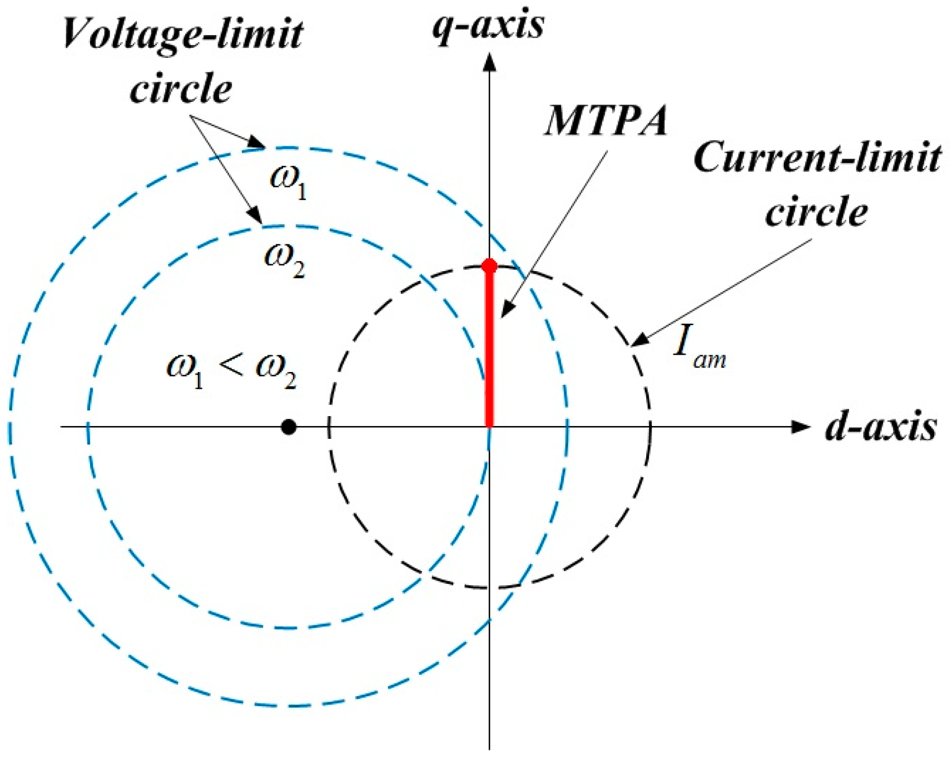
Figure 3.
A block diagram of the proposed torque error compensation control system for SPMSM drives.
Figure 3.
A block diagram of the proposed torque error compensation control system for SPMSM drives.

Figure 4.
Simulation results of a frequency response of the Gopinath style stator flux linkage observer with respect to motor parameter variations.
Figure 4.
Simulation results of a frequency response of the Gopinath style stator flux linkage observer with respect to motor parameter variations.

Figure 5.
Simulation results of a torque response of a SPMSM drive with and without torque error compensation algorithm when a PM flux linkage is changed 20% from its initial value (Operating condition: ωr = 300 rad/s).
Figure 5.
Simulation results of a torque response of a SPMSM drive with and without torque error compensation algorithm when a PM flux linkage is changed 20% from its initial value (Operating condition: ωr = 300 rad/s).

Figure 6.
Demagnetization ratio curves of the test SPMSM with respect to temperature variations.

Figure 7.
Experimental measurement of PM temperature of the test SPMSM.

Figure 8.
Experimental test set up of a gauss meter.

Figure 9.
Variation of permanent magnet flux linkage distribution with respect to temperature changes from 25 to 100 °C.
Figure 9.
Variation of permanent magnet flux linkage distribution with respect to temperature changes from 25 to 100 °C.
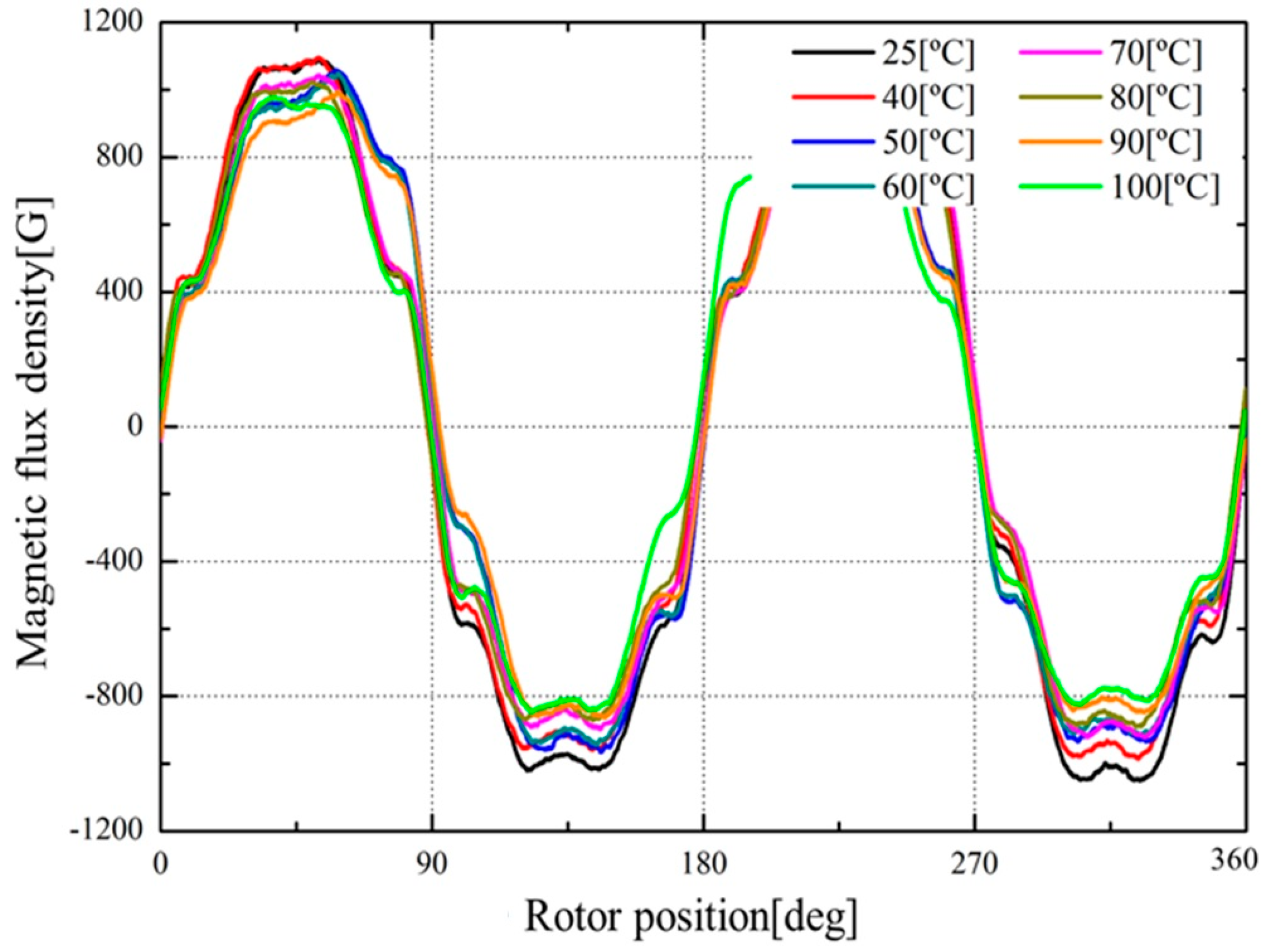
Figure 10.
Experimental test set up
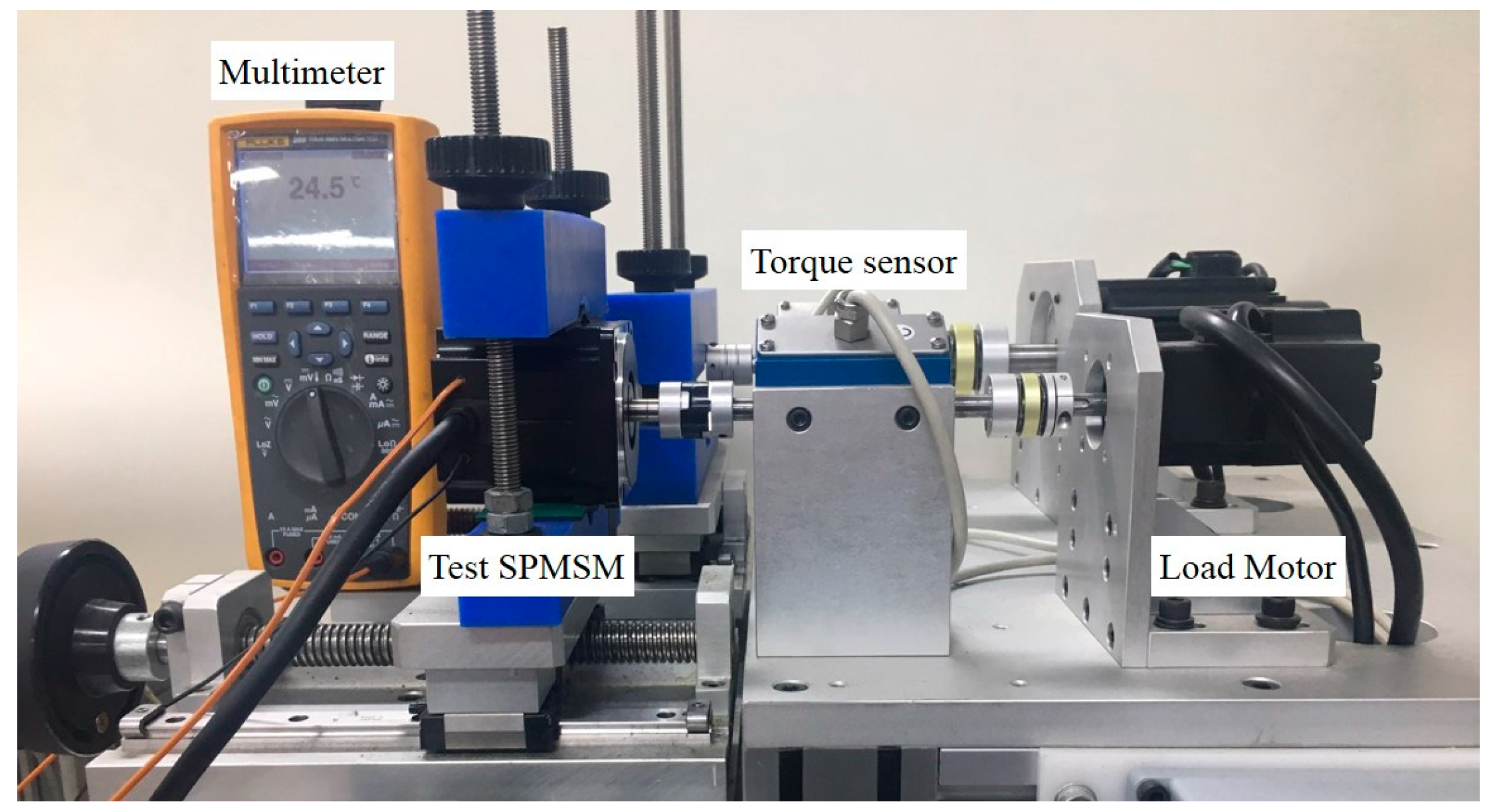
Figure 11.
Comparison of torque control characteristics between current-voltage model and voltage model (a) permanent magnet temperature = 25 °C (b) permanent magnet temperature = 100 °C (Operating condition: ωr = 65 rad/s, Torque command: 127 mNm).
Figure 11.
Comparison of torque control characteristics between current-voltage model and voltage model (a) permanent magnet temperature = 25 °C (b) permanent magnet temperature = 100 °C (Operating condition: ωr = 65 rad/s, Torque command: 127 mNm).
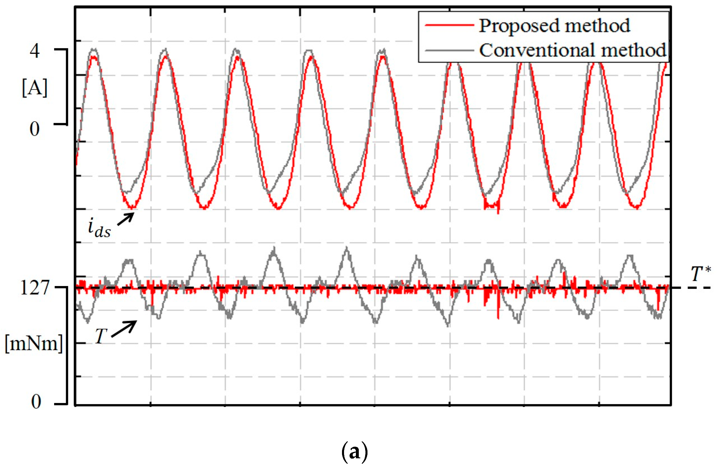

Figure 12.
Characteristics of a SPMSM drive without applying the proposed algorithm (Operating condition: ωr = 620 rad/s, permanent magnet temperature = 25 °C).
Figure 12.
Characteristics of a SPMSM drive without applying the proposed algorithm (Operating condition: ωr = 620 rad/s, permanent magnet temperature = 25 °C).
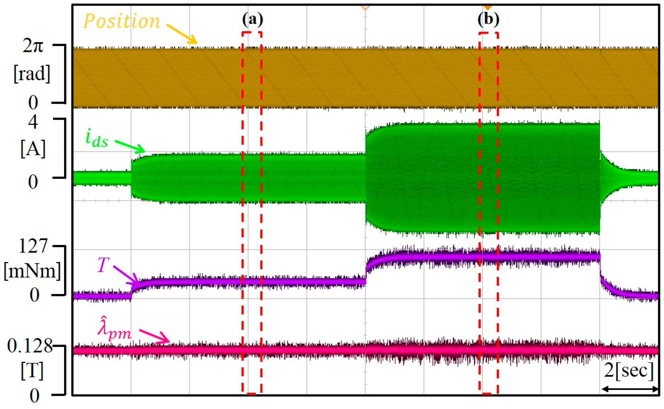
Figure 13.
Steady state responses of the test SPMSM drive without applying the proposed algorithm. (a) Torque command: 50 mNm (b) Torque command: 127 mNm. (Operating condition: ωr = 620 rad/s, permanent magnet temperature = 25 °C).
Figure 13.
Steady state responses of the test SPMSM drive without applying the proposed algorithm. (a) Torque command: 50 mNm (b) Torque command: 127 mNm. (Operating condition: ωr = 620 rad/s, permanent magnet temperature = 25 °C).
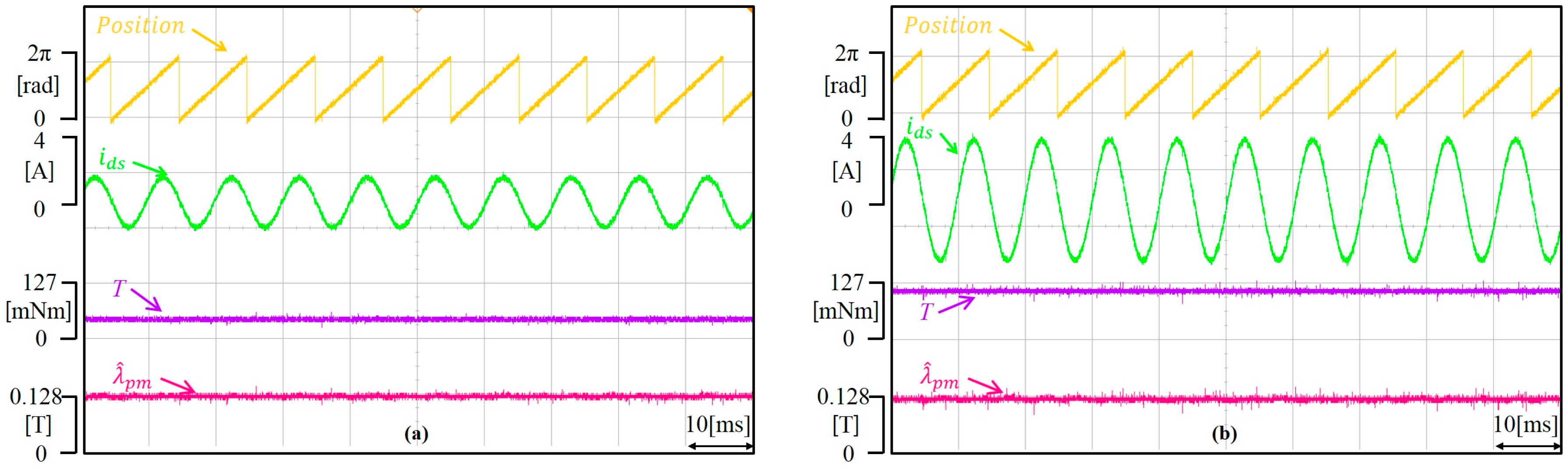
Figure 14.
Output waveform of the motor performance tester. (Operating condition: ωr = 620 rad/s, permanent magnet temperature = 25 °C).
Figure 14.
Output waveform of the motor performance tester. (Operating condition: ωr = 620 rad/s, permanent magnet temperature = 25 °C).
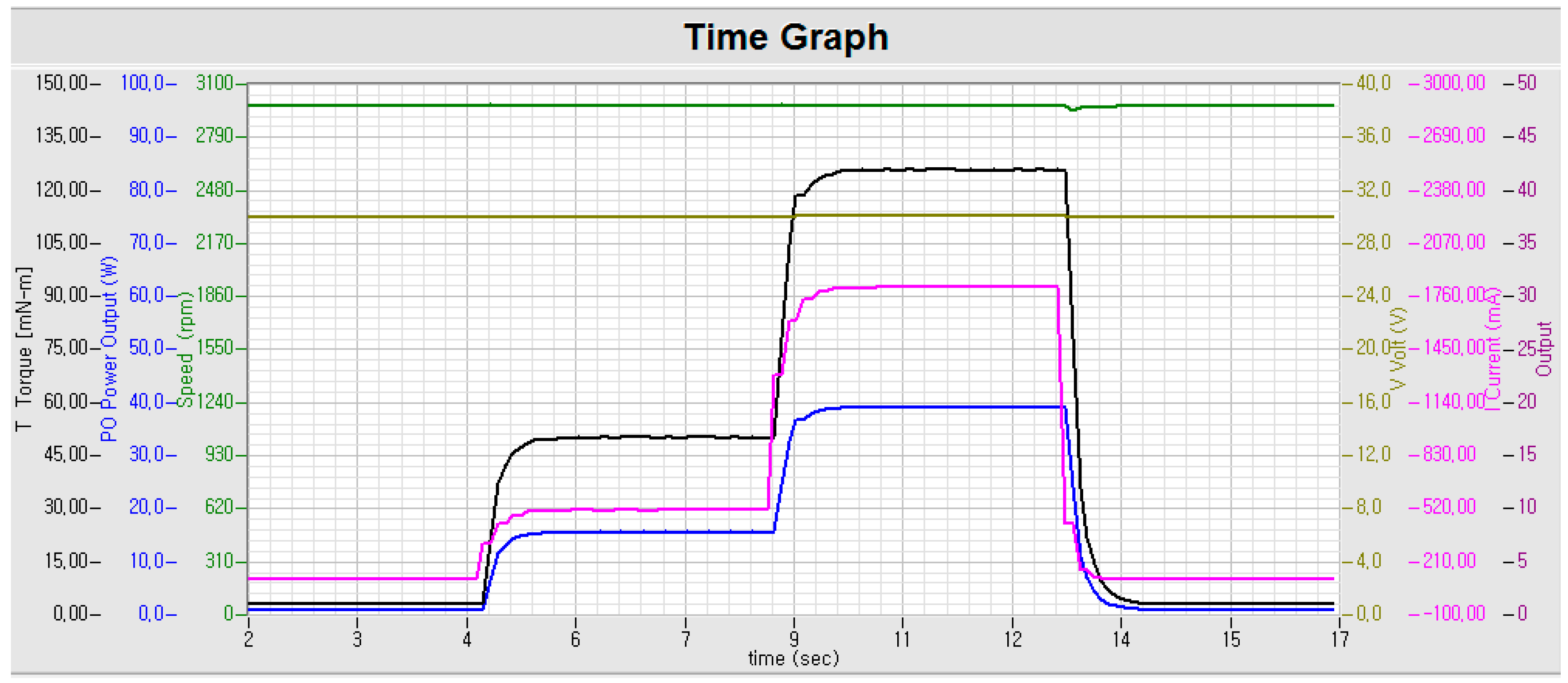
Figure 15.
Characteristics of a SPMSM drive without applying the proposed algorithm. (Operating condition: ωr = 620 rad/s, PM temperature = 100 °C).
Figure 15.
Characteristics of a SPMSM drive without applying the proposed algorithm. (Operating condition: ωr = 620 rad/s, PM temperature = 100 °C).

Figure 16.
Steady state responses of the test SPMSM drive without applying the proposed algorithm. (a) Torque command: 50 mNm (b) Torque command: 127 mNm (Operating condition: ωr = 620 rad/s, permanent magnet temperature = 100 °C).
Figure 16.
Steady state responses of the test SPMSM drive without applying the proposed algorithm. (a) Torque command: 50 mNm (b) Torque command: 127 mNm (Operating condition: ωr = 620 rad/s, permanent magnet temperature = 100 °C).
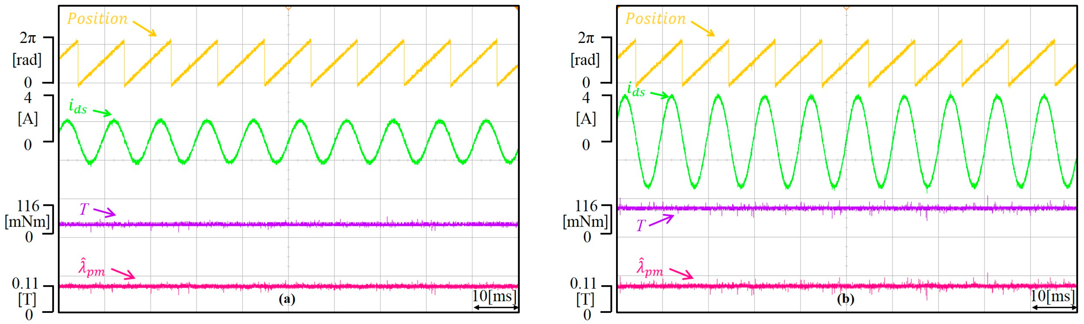
Figure 17.
Output waveform of the motor performance tester. (Operating condition: ωr = 620 rad/s, permanent magnet temperature = 100 °C).
Figure 17.
Output waveform of the motor performance tester. (Operating condition: ωr = 620 rad/s, permanent magnet temperature = 100 °C).
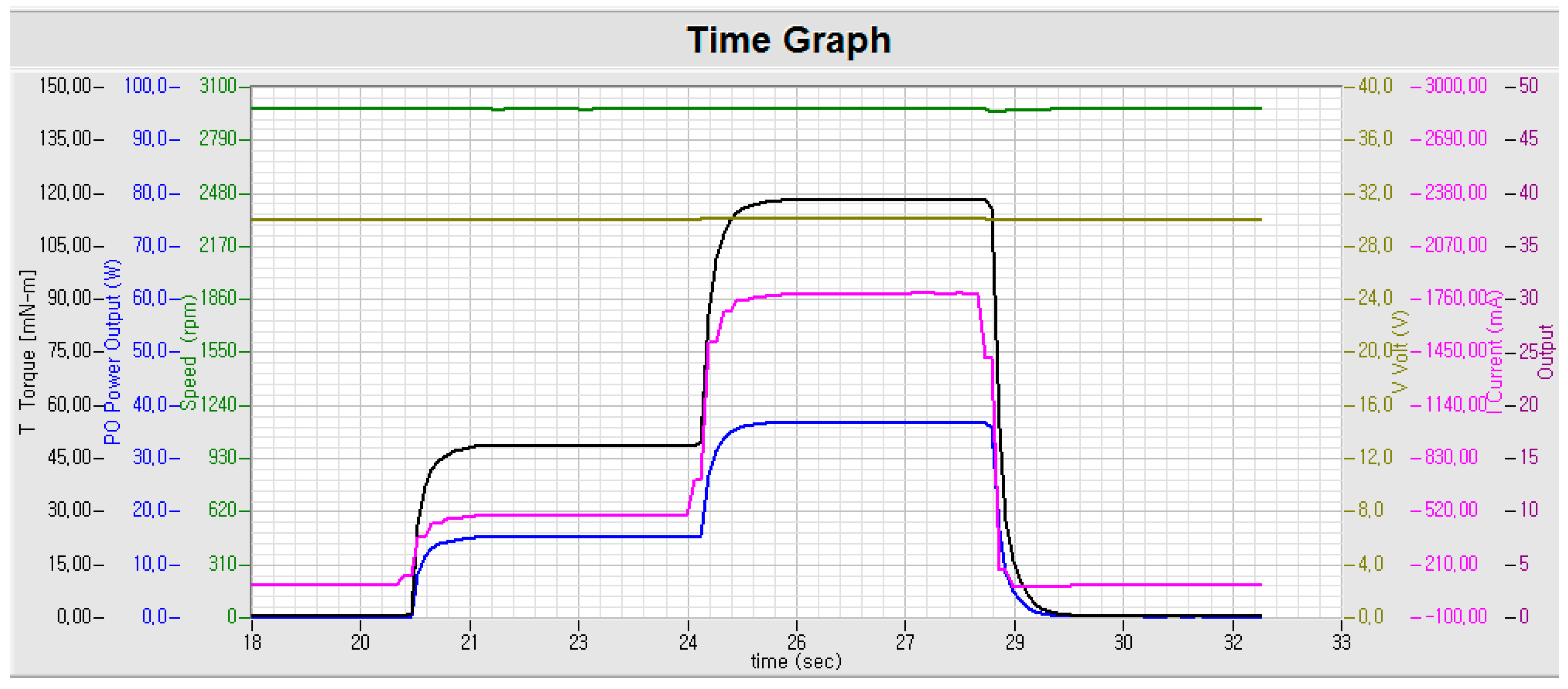
Figure 18.
Torque response characteristics of a SPMSM drive in the room temperature with proposed algorithm. (Operating condition: ωr = 620 rad/s, PM temperature = 100 °C).
Figure 18.
Torque response characteristics of a SPMSM drive in the room temperature with proposed algorithm. (Operating condition: ωr = 620 rad/s, PM temperature = 100 °C).
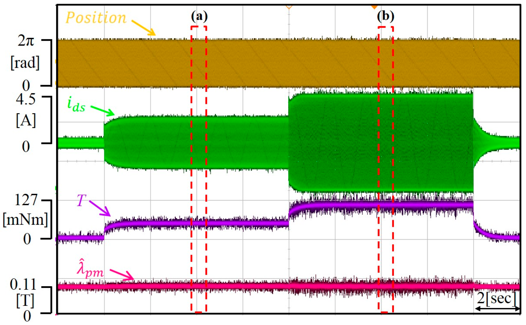
Figure 19.
Output current and output torque characteristics according to torque command. (a) Torque command: 50 mNm (b) Torque command: 127 mNm.
Figure 19.
Output current and output torque characteristics according to torque command. (a) Torque command: 50 mNm (b) Torque command: 127 mNm.

Figure 20.
Output waveform of the motor performance tester.


Table 1.
Parameters of SPMSM drive.
| Parameters | Values | Parameters | Values |
|---|---|---|---|
| Stator resistance | 0.75 | Bus voltage | 25 V |
| Stator inductance | 0.85 mH | Rated current | 2.8 A |
| PM flux linkage | 0.128 T | Rated speed | 310 rad/s |
| Poles | 4 | Torque sensor capacity | 0.5 Nm |
| Rated torque | 0.127 Nm | PWM sampling time | 100 |
| Inverter switch type | IGBT (Insulated Gate Bipolar Mode Transistor) | Dead time | 3 |
© 2017 by the authors. Licensee MDPI, Basel, Switzerland. This article is an open access article distributed under the terms and conditions of the Creative Commons Attribution (CC BY) license (http://creativecommons.org/licenses/by/4.0/).
Share and Cite
MDPI and ACS Style
Park, C.-S.; Lee, J.S. A Torque Error Compensation Algorithm for Surface Mounted Permanent Magnet Synchronous Machines with Respect to Magnet Temperature Variations. Energies 2017, 10, 1365. https://doi.org/10.3390/en10091365
AMA Style
Park C-S, Lee JS. A Torque Error Compensation Algorithm for Surface Mounted Permanent Magnet Synchronous Machines with Respect to Magnet Temperature Variations. Energies. 2017; 10(9):1365. https://doi.org/10.3390/en10091365
Chicago/Turabian StylePark, Chang-Seok, and Jae Suk Lee. 2017. "A Torque Error Compensation Algorithm for Surface Mounted Permanent Magnet Synchronous Machines with Respect to Magnet Temperature Variations" Energies 10, no. 9: 1365. https://doi.org/10.3390/en10091365
Note that from the first issue of 2016, this journal uses article numbers instead of page numbers. See further details here.