Improved Reactive Current Detection Method of SVG

1
College of Geophysics and Information Engineering, China University of Petroleum-Beijing, Beijing 100000, China
2
School of Automation, Wuhan University of Technology, Wuhan 430000, China
*
Author to whom correspondence should be addressed.
Energies 2017, 10(9), 1374; https://doi.org/10.3390/en10091374
Submission received: 18 July 2017
/
Revised: 26 August 2017
/
Accepted: 5 September 2017
/
Published: 10 September 2017
(This article belongs to the Special Issue Emerging Power Electronics Technologies for Power Systems and Machine Drives)
Abstract
:The static VAR generator (SVG) is an important device in flexible AC transmission systems (FACTS) for the development of smart grids. Based on the basis principle of SVG and instantaneous reactive power theory, the conventional ip–iq and dq methods have a certain error when the three phase voltages are unbalanced. In this paper, the current detection algorithm is improved in cases of three-phase power asymmetry by using the fundamental positive-sequence reactive current instead of the voltage as the input of phase locked loop (PLL). So the problems caused by unbalanced three-phase voltages could be avoided. In addition, a moving average filter is designed to improve the performance of the detection accuracy and dynamic response. Experiments verify the correctness and effectiveness of the proposed scheme.
1. Introduction
As low-voltage distribution networks are becoming more and more popular and electronic devices attract much more attention, the quality of power systems is becoming an increasingly greater issue of concern. With the rapid development of high-voltage high-power power electronic equipment, flexible AC transmission systems (FACTS) are typically applied to the intelligent power grid [1]. The static VAR generator (SVG) is one of the important elements of FACTS, which has wide range, good dynamic characteristics, and the ability to track and compensate for reactive power quickly once the grid changes [2,3,4], including compensation for inductive reactive power and capacitive reactive power. With the advantages of fast compensation speed, high compensation precision, and wide compensation range, SVGs have become a mainstream trend of development [5,6].
SVGs play an important role in improving the voltage quality and ensuring the normal operation of FACTS [7,8,9]. When a large number of power quality problems caused by the nonlinearity and imbalance characteristics of the load occur [10], an SVG is implemented on the load side to realize reactive power compensation, harmonic suppression and three-phase imbalance compensation, etc. The performance of the SVG in a grid system depends on the real-time accuracy of the reactive current detection and the effectiveness of the system control strategy. Therefore, the study of reactive current detection algorithms and the optimization of SVG control strategy are the important routes to improve the SVG reactive power compensation system [11,12]. At present, reactive power detection algorithms (i.e., pq, ip–iq, and dq method) based on instantaneous reactive power theory is the most widely used in SVG reactive power compensation system [13,14]. However, the pq method and ip–iq method in the case of three-phase voltage distortion have a certain error when the three phase voltages are unbalanced, while dq detection method can be used for reactive current detection of three-phase voltage distortion since it has a high detection accuracy and is widely used.
Based on the working principle of SVG direct current control, considering the common situation of three-phase grid asymmetry, the phase-locked loop (PLL) in the detection method based on instantaneous reactive power theory is improved, and the single-phase fundamental reactive current is used to replace the phase-component of the single-phase grid voltage to lock the phase and eliminate detection bias. In addition, the existence of low-pass filter (LPF) in the detection algorithm also has great influence on the steady-state and dynamic performance of the system, and the sliding-averaging filter (SMF) is designed to improve the detection compensation performance of SVG in consideration of both the detection accuracy and the response speed. Finally, experimental results verify the correctness and effectiveness of the proposed scheme.
2. Mathematical Model Analysis of SVG
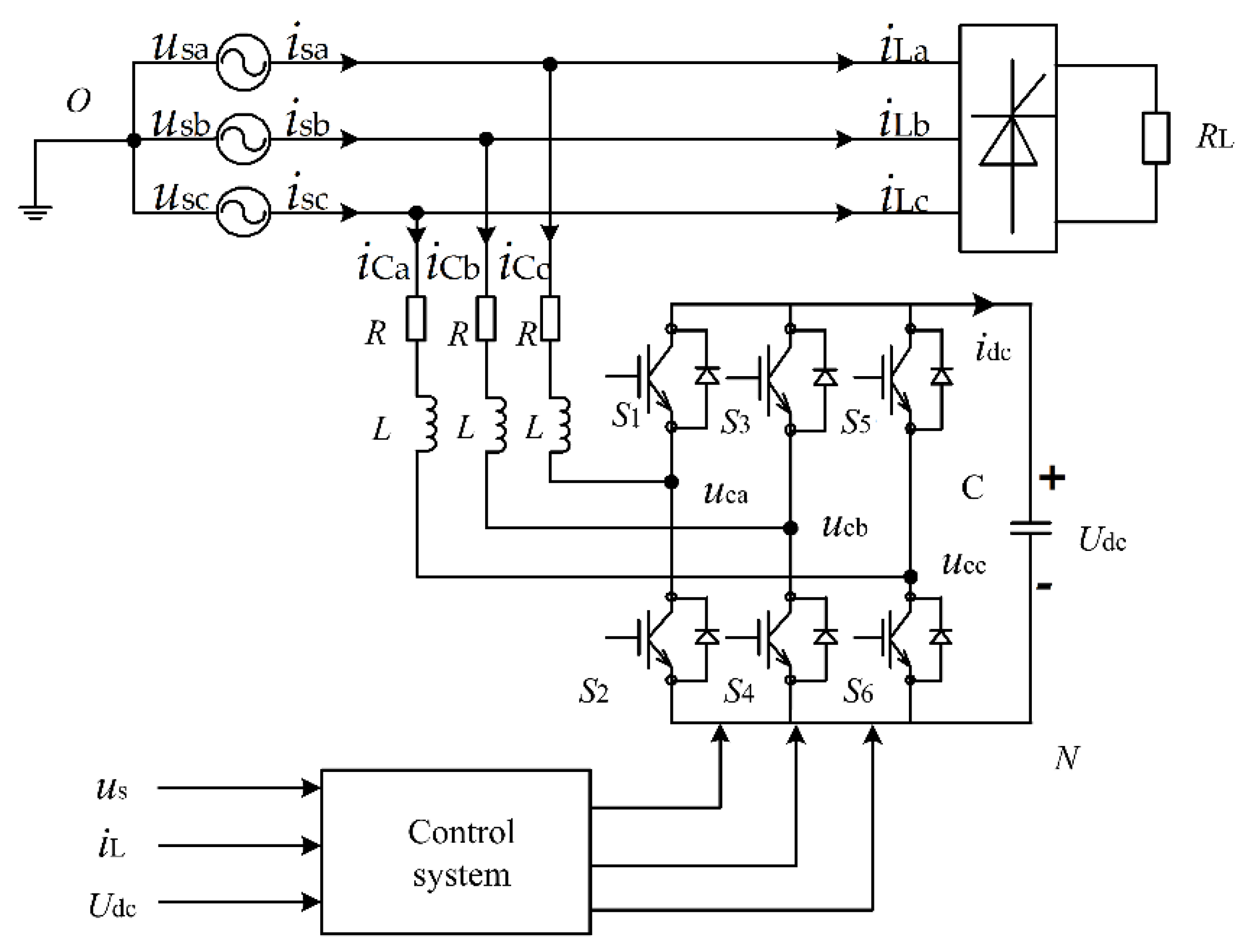
The structure of the SVG is shown in Figure 1 including the main circuit and control system. The main circuit is a three-phase bridge inverter connected to the power grid through the reactor. By controlling the switches S1–S6 in the main circuit, the inverter absorbs a small amount of active current from the AC system to charge the DC bus capacitor C, without external power supply to maintain its voltage. In the SVG control system, by adjusting the output voltage or current of the bridge inverter the required reactive power can be produced in the grid control in order to compensate for reactive power of the grid.
In order to realize the active and negative decoupling control, the AC signal in a three-phase stationary coordinate system is transformed into the two-phase rotation dq coordinate system. A mathematical model of the SVG in dq coordinate system [15] (assuming three-phase grid balance) is:
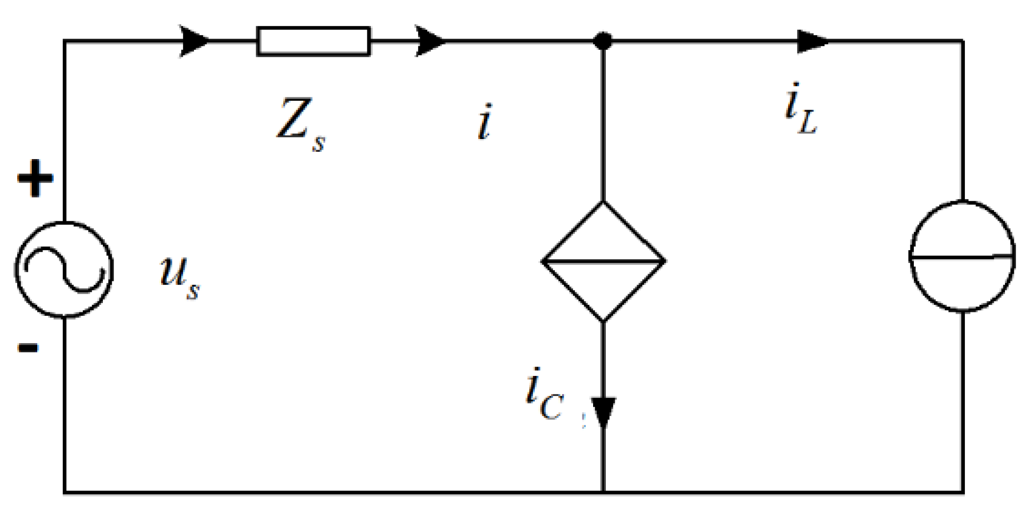
The direct current control method is generally used in active filter medium and low voltage SVG, the compensation principle is shown in Figure 2. The load is considered as a current source and the SVG is also controlled to be a current source. When the reactive component of the load current iL needs to be compensated, the iC is controlled to have the same magnitude and opposite direction of that, so as to offset the reactive components of the power side current to achieve the purpose of reactive power compensation.
3. Research on Reactive Current Detection Method
3.1. Reactive Current Detection Based on Instantaneous Reactive Power Theory
Reactive power compensation mainly includes harmonic and fundamental phase shifts. Within the allowable range of the device, an SVG should compensate for both harmonics and fundamental reactive power except the fundamental active components. In practical engineering applications, fundamental reactive power accounts for the majority of the proportion in all reactive power loss. In order to reduce the switching frequency and improve system capacity, the reactive power can be compensated to a certain range only with fundamental reactive power compensation.
The basic principle is to separate the reactive components in the fundamental load current. Based on the matrix transformation, the fundamental components of the input three-phase load current is converted into a DC component in the corresponding coordinates. The DC component containing a fundamental reactive current is separated through the Low Pass Filter (LPF) [16] and is then inverse transformed into reactive current command. In addition, the inverse transform of the active component is used to control the stability of the DC side capacitor voltage.
In most power grids, three-phase voltage asymmetry is more common, which is assumed as:
where + represents the positive sequence voltage component and − represents the negative sequence voltage component.
Based on the symmetric component theory, the three-phase distortion asymmetric current can be decomposed into:
where: In+, In−, In0 (n = 1, 2, 3, ...) denote positive sequence, negative sequence, and zero sequence components of each current respectively; φn+, φn−, φn0 denote the positive order, negative order, and zero sequence initial phase angle respectively.
The signals sinωt and cosωt of the dq detection method are obtained by phase-locking the voltage ua. When the three-phase grid voltage is asymmetric, ua contains negative sequence components, then the phase obtained by the latching of ua equals the sum of the positive sequence component and the negative sequence component of ua, θ is a deviation from the phase of the desired positive sequence component of ua. The transformation matrix is assumed as:
Three-phase distortion asymmetric current can be converted to the Formula (5) through dq conversion:
The DC component in the above equation is extracted by the LPF as shown in Equation (6):
Then, the inverse of the dq inverse transform of iq is obtained as shown in Equation (7):
It can be seen from the above equation that when the three-phase voltage is asymmetric, the fundamental positive sequence reactive current deduced from the dq inverse transformation of iq has a deviation because of the existence of θ.
3.2. Improved Reactive Current Detection Method
3.2.1. Improved dq Detection Algorithm Based on Instantaneous Reactive Power
Based on the power quality standards, the asymmetry of the three-phase voltage at the Point of Common Coupling (PCC) of the system is less than 2% and less than 4% for a short time [17]. The method of current detection based on ip–iq principle is described in Figure 3. In this method, it is very sensitive to voltage and frequency conversion of the network and unbalance of the three-phase network. Therefore, the improved PLL with dq detection method based on the instantaneous reactive power can be directly applied to the symmetrical or asymmetrical system, since it has the advantages of simple detection principle, less computational demand, flexibility, and more accurate detection of reactive current, the specific block diagram is shown in Figure 4.
The three-phase fundamental positive sequence reactive current is obtained through the reverse dq transformation.
Therefore, the improved output of the three-phase grid fundamental positive sequence reactive current ia1q+ is symmetrical and has the same frequency with grid voltage, so the grid voltage ua containing negative sequence component can be replaced by the detected ia1q+ to lock the phase to obtain sinωt and cosωt. So the detection error brought by the negative voltage component of the grid can be eliminated, and the closed-loop system further reduces the detection error.
3.2.2. Design of Sliding Average Filter
In addition, on the basis of improving the PLL, the response speed and detection accuracy of the dq detection method mainly depends on the design of the LPF and finally affects the reactive power compensation performance of the SVG. The design becomes an important link to the stability and dynamic performance of the algorithm. In order to compensate for the inherent delay of commonly used LPF and eliminate the contradiction between detection accuracy and dynamic response speed—and considering the digital storage process space, calculation, and other issues—SMF is designed to replace the commonly used Butterworth LPF to improve the system's real-time dynamic response speed, and achieve better filtering performance.
When SVG is working for reactive compensation, the main purpose of LPF is to separate the DC component of the signal, which is the key link of the fundamental reactive current detection algorithm. Since the DC component of q-axis current corresponds to the fundamental reactive power of the load and the AC component of the q-axis current corresponds to the harmonic power, all sampling points in a cycle are summed to zero for AC components. However, the sum of all the sample points in a sinusoidal period divided by the number of samples is still the DC signal for a DC signal. Therefore, the basic idea of the average filter is to select a cycle, then accumulate the signals at the sampling point and divide the accumulation by the number of sampling points before entering the LPF, to get the DC signal result.
In order to reflect the dynamic real-time compensation performance of SVG, according to the repeatability of each cycle of the AC signal, considering sampling the kth point, the current new information is used to cover the information of the same position before a cycle, and so on. So the latest average is equal to the division by the number of samples of the new data sampled per cycle minus the oldest data, plus the average of the calculations in a cycle. The recursive formula is deduced as
where ild(k) is the current new information, ild(k − N) is the old information of last cycle corresponding to the current moment.
When the input signal amplitude and frequency are not changed, the sliding average output does not change. Once the signal changes, the sliding average output also changes, approaching the true value. The moving average algorithm reflects the speed of data updating in terms of the true value of a periodic average method after a cycle.
In order to achieve the data update, there must be N data units to store sample point information. In this experiment, the sampling frequency is 9.6 KHz. For a fundamental cycle, 192 data storage space is required, the general DSP processor is very easy to achieve this requirement.
The expression in Z field according to the above formula is written as:
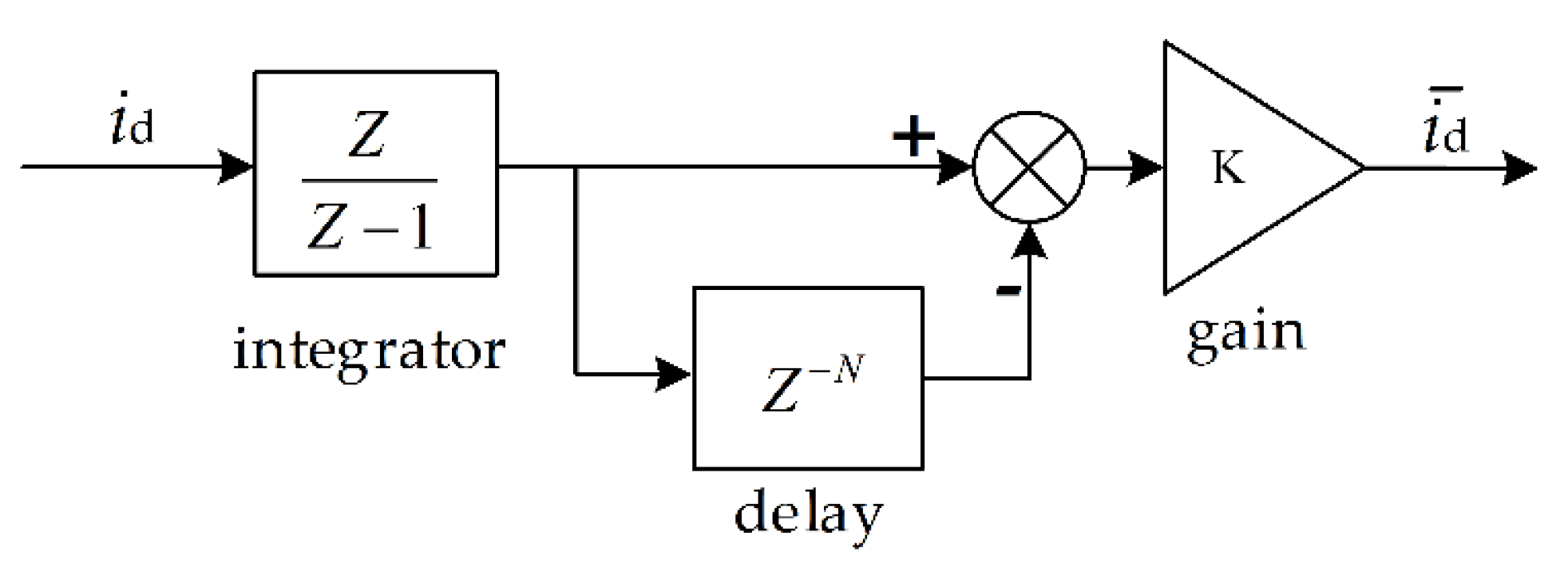
The model of the SMF is established according to (10) in Figure 5.
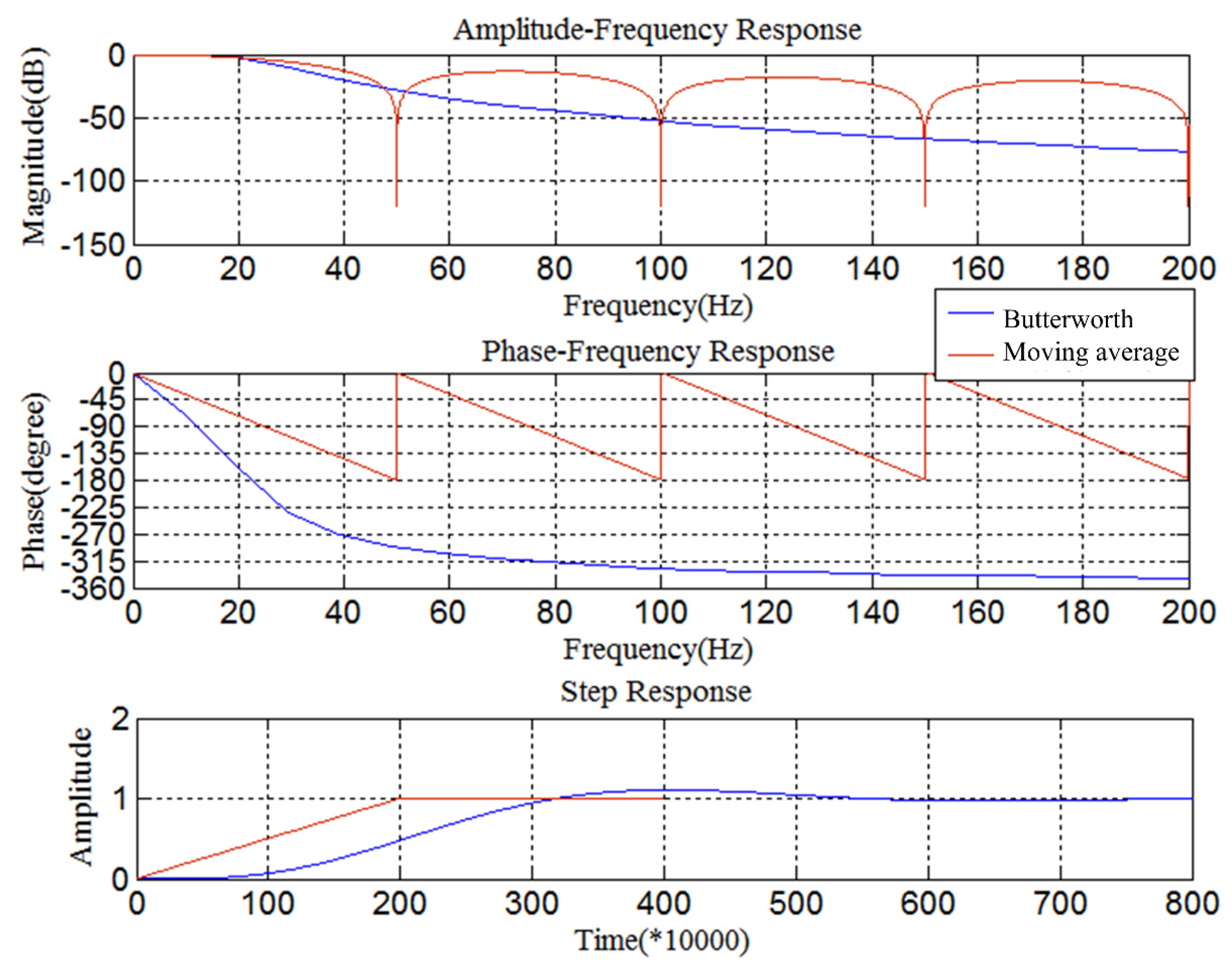
Analyze the comparison of the SMF with the common Butterworth LPF, by Setting the sampling frequency to 10 kHz and N = 200. The Bode plot and step response curves of the SMF, and the fourth-order Butterworth LPF with a cutoff frequency of 22 Hz are drawn.
As shown in Figure 6, both the Butterworth LPF and the SMF have flat passband amplitude-frequency characteristics. Unlike the Butterworth LPF, the SMF is rapidly attenuated in the transition zone and the stopband, and has a linear phase, and the step response is fast without overshoot and can enter a steady state in 0.02 s. Therefore, for reactive current detection, the SMF can both meet the detection accuracy and have a faster dynamic response speed.
In the detection of reactive current based on instantaneous power theory, SMF can greatly reduce the amount of calculation. It is easy to realize the programming of a DSP chip in engineering practice. The program avoids mathematical floating-point operations of the traditional digital LPF, reduces latency, and improve the real-time performance of reactive power compensation, also has better real-time performance with better dynamic response.
4. Experiment Analysis
The experimental prototype of 100 kVA SVG is shown in Figure 7. The application of the SMF in the reactive current detection algorithm of an SVG system, the influence of steady-state compensation accuracy and dynamic response performance of the SVG system are studied.
4.1. Experimental Waveform Analysis of SVG with RL Load
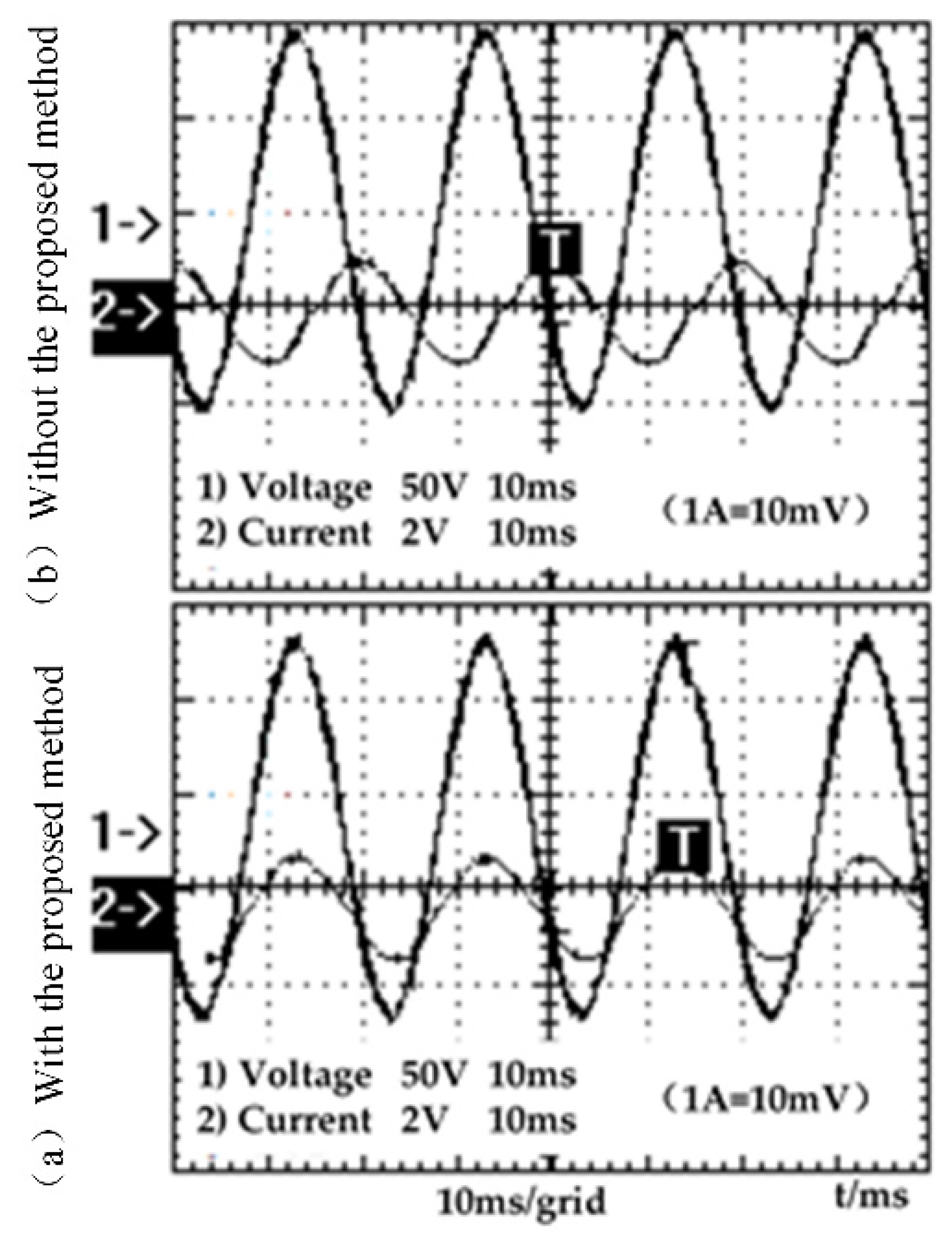
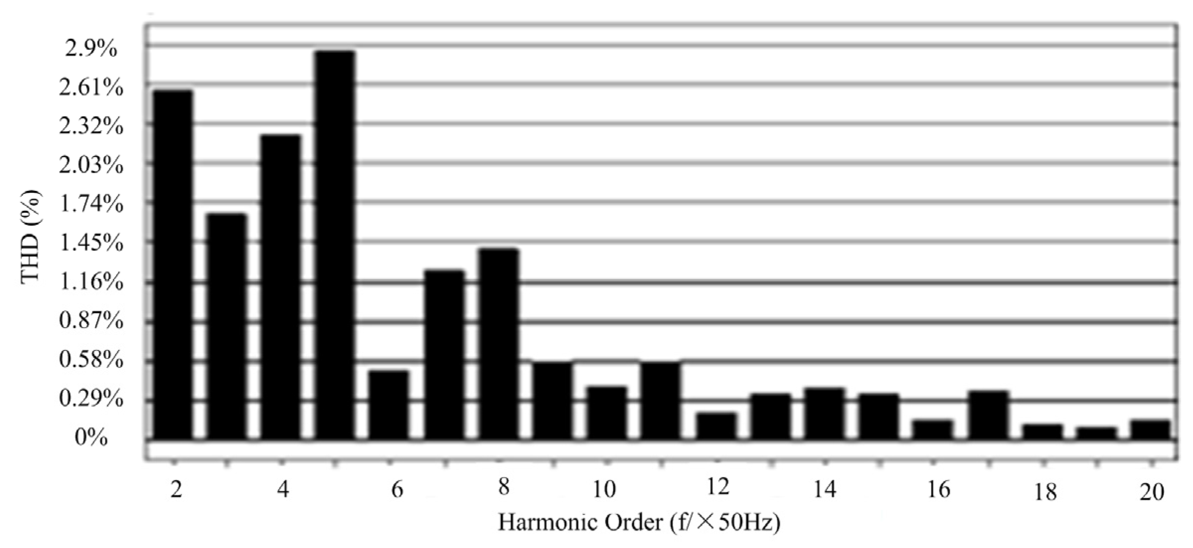
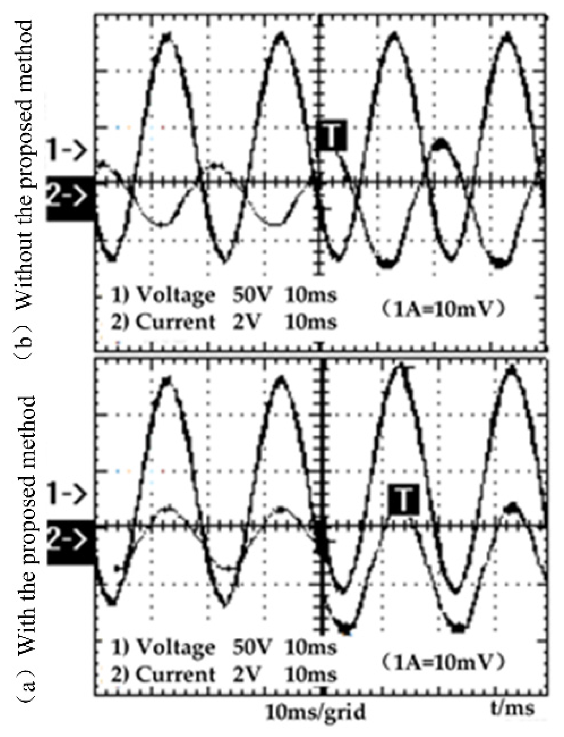
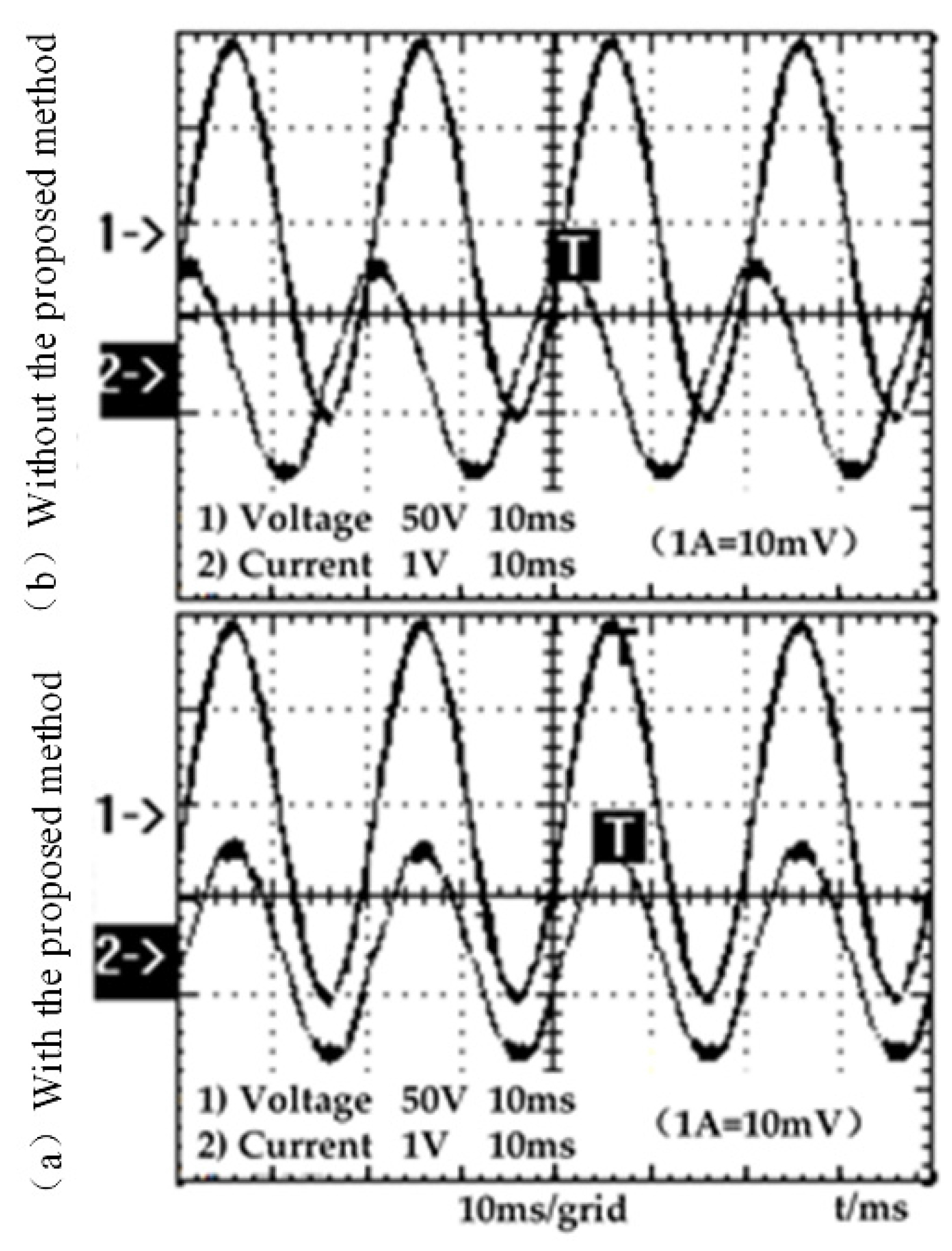
The RL load is used in this experiment, Figure 8 is the DC side voltage and reactive current of the experimental waveform, in the compensation process, the DC side voltage can be maintained at a stable value to ensure the safe and reliable operation of the entire device. The compensation effect is achieved as shown in Figure 9 the current phase of the RL load is lagging behind the voltage before the compensation. After the SVG is inputted, the voltage and current almost have the same phase, which effectively compensates the reactive power consumed by the inductive load. As the current spectrum shown in Figure 10, the AC side current harmonic distortion THD reaches 2.9% after the compensation. Therefore, the SVG system using a moving average LPF can meet the compensation accuracy requirements.
Dynamic response test waveform is shown in Figure 11. SVG system can quickly track the load current changes once the load current and the entire circuit reactive power changes, whose faster response can meet the dynamic response performance demands.
4.2. Experimental Waveform Analysis SVG with RC Load
For the RC load, SVG can also offer capacitive reactive power compensation as shown in Figure 12. After the SVG is inputted, the voltage and current almost have the same phase, capacitive reactive power is close to 0, and power factor can reach 0.95 meeting the compensation requirements.
So SVG can compensate for both inductive reactive power and capacitive reactive power, and continuously adjust the system reactive power, and has faster dynamic adjustment.
5. Conclusions
In this paper, based on the principle of direct current compensation of SVG, the phase-locked loop in the instantaneous reactive current detection method is improved for the case of an asymmetric three-phase power grid, and the moving average LPF is used instead of the commonly used LPF. The goal of achieving the detection accuracy and dynamic response performance is realized, and the algorithm is small, so it is easy to achieve in the DSP programming. The experimental results show that the SVG system can effectively compensate the reactive power on the three-phase grid side, and have better dynamic response performance compared with the widely used Butterworth LPF, which has certain reference value and applicability.
Author Contributions
This research was supported by the project National Natural Science Foundation of China (Grant No: 51777146). Xueliang Wei conceived and designed the study. Jianghua Lu, Wenjing Li and Erjie Qi were responsible for the simulations and experiments. This work was performed under the advisement and regular feedback from Guorong Zhu.
Conflicts of Interest
The authors declare no conflict of interest.
References
- Elmoursi, M.S.; Sharaf, A.M. Voltage stabilization and reactive compensation using a novel FACTS STATCOM scheme. In Proceedings of the Canadian Conference on Electrical and Computer Engineering, Saskatoon, SK, Canada, 1–4 May 2005; pp. 537–540. [Google Scholar]
- Sun, Y.; Li, S.H. Comparison of Conventional and A Novel Direct Current Vector Control Approaches for a LCL-filter based STATCOM. In Proceedings of the IEEE Power & Energy Society General Meeting, Denver, CO, USA, 26–30 July 2015; pp. 103–107. [Google Scholar]
- Zhao, J.Q.; Liu, X.; Lin, C.N.; Wei, W.H. Three-Phase Unbalanced Voltage/VAR Optimization for Active Distribution Networks. In Proceedings of the IEEE Power and Energy Society General Meeting (PESGM), Boston, MA, USA, 17–21 July 2016; pp. 1–5. [Google Scholar]
- Raj, G.S.; Rathi, K. P-Q theory based Shunt Active Power Filter for power quality under ideal and non-ideal grid voltage conditions. In Proceedings of the Power, Instrumentation, Control and Computing (PICC), Thrissur, India, 9–11 December 2015; pp. 1–5. [Google Scholar]
- Dixon, J.; Del Valle, Y.; Orchard, M.; Ortuzar, M.; Moran, L.; Maffrand, C. A full compensating system for general loads, based on a combination of thyristor binary compensator, and a PWM-IGBT active power filter. IEEE Trans. Ind. Electron. 2003, 50, 982–989. [Google Scholar] [CrossRef]
- Akagi, H.; Ogasawara, S.; Kim, H. The theory of instantaneous power in three-phase four-wire systems: A comprehensive approach. IEEE Trans. Ind. Appl. 1999, 1, 431–439. [Google Scholar]
- Blazic, B.; Papic, I. Improved D-StatCom control for operation with unbalanced currents and voltages. IEEE Trans. Power Deliv. 2006, 21, 225–233. [Google Scholar] [CrossRef]
- Cavaliere, C.A.C.; Watanabe, E.H.; Aredes, M. Multi-pulse STATCOM operation under unbalanced voltages. In Proceedings of the 2002 IEEE Power Engineering Society Winter Meeting, New York, NY, USA, 27–31 January 2002; pp. 567–572. [Google Scholar]
- Liao, W.D.; Qi, Q. A New Method Highly Integrated with Converter Transformer for Harmonic Suppression and Reactive Power Compensation. In Proceedings of the International Conference on Power System Technology, Chengdu, China, 20–22 October 2014; pp. 1576–1581. [Google Scholar]
- Schwanz, D.; Moller, F.; Ronnberg, S.K.; Bollen, M.H.J. Stochastic Assessment of Voltage Unbalance Due to Single-Phase-Connected Solar Power. IEEE Trans. Power Deliv. 2017, 32, 852–861. [Google Scholar] [CrossRef]
- Wang, H.; Li, Q.; Wu, M. Investigation on a New Algorithm for Instantaneous Reactive and Harmonic Currents Detection Applied to Intensive Nonlinear Loads. IEEE Trans. Power Deliv. 2007, 22, 2312–2318. [Google Scholar] [CrossRef]
- Yang, X.F.; Fan, W.B.; Wang, X.P.; Zheng, Q.L. Static Synchronous Compensator Based on Modular Multilevel Converter Based STATCOM and Its Control. Trans. China Electrotech. Soc. 2011, 26, 7–13. [Google Scholar]
- Wang, L.; Lam, C.-S.; Wong, M.-C. Design of a Thyristor Controlled LC Compensator for Dynamic Reactive Power Compensation in Smart Grid. IEEE Trans. Smart Grid 2017, 8, 409–417. [Google Scholar] [CrossRef]
- Pattnaik, S.; Swain, S.C.; Dash, R.; Mohapatra, R. Control of Active and Reactive Power of A Three Phase Grid Connected Photovoltaic System. In Proceedings of the International Conference on Circuit, Power and Computing Technologies (ICCPCT), Nagercoil, India, 18–19 March 2016; pp. 1–6. [Google Scholar]
- Zhang, Y.; Yi, Y.; Dong, P.; Liu, F.; Kang, Y. Simplified Model and Control Strategy of Three-Phase PWM Current Source Rectifiers for DC Voltage Power Supply Applications. IEEE J. Emerg. Sel. Top. Power Electron. 2015, 3, 1090–1099. [Google Scholar] [CrossRef]
- Kong, X.; Yuan, Y.; Huang, H.; Wang, Y. Overview of the instantaneous reactive power theory in three-phase systems. In Proceedings of the 5th International Conference on Electric Utility Deregulation and Restructuring and Power Technologies (DRPT 2015), Changsha, China, 26–29 November 2015. [Google Scholar]
- Gagrica, O.; Uhl, T.; Nguyen, P.H.; Cobben, J.F.G. Applicability of true voltage unbalance approximation formula for unbalance monitoring in LV networks with single-phase distributed generation. In Proceedings of the International Conference on Smart Cities and Green ICT Systems (SMARTGREENS), Rome, Italy, 23–25 April 2016; pp. 1–7. [Google Scholar]
Figure 1.
The diagram of SVG main circuit structure.

Figure 2.
The schematic of direct current control for SVG.

Figure 3.
The method of current detection based on ip-iq principle.
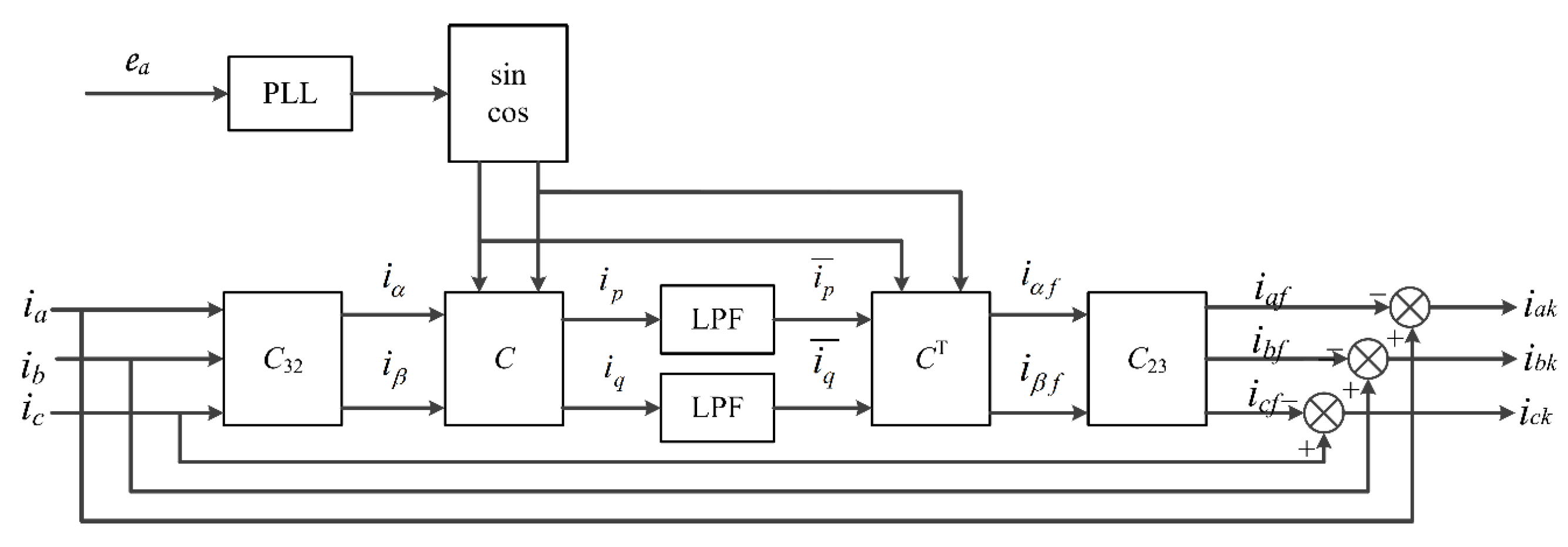
Figure 4.
Block diagram of reactive current detection for SVG.
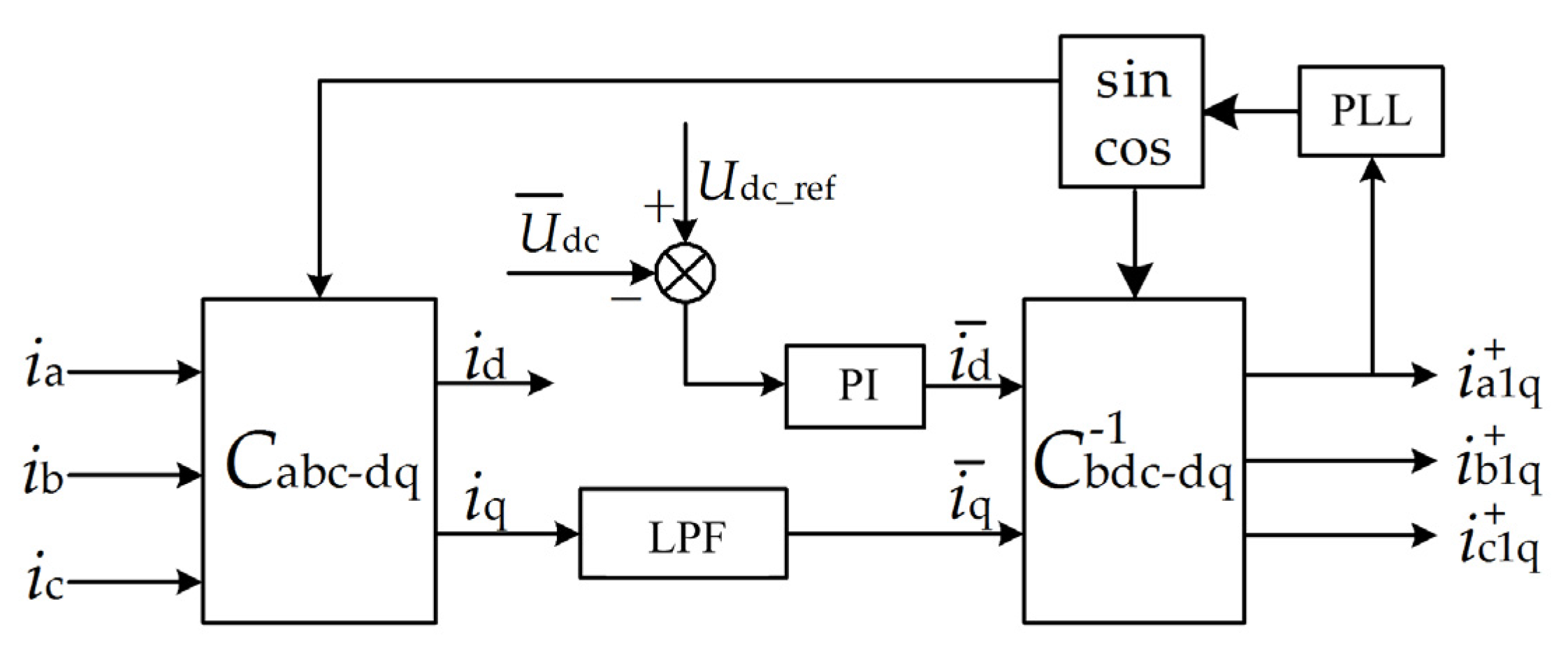
Figure 5.
The model of a moving average low-pass filter.

Figure 6.
The frequency response and step response of the moving average filter and Butterworth low-pass filter.
Figure 6.
The frequency response and step response of the moving average filter and Butterworth low-pass filter.

Figure 7.
Experimental prototype of 100kVA SVG.
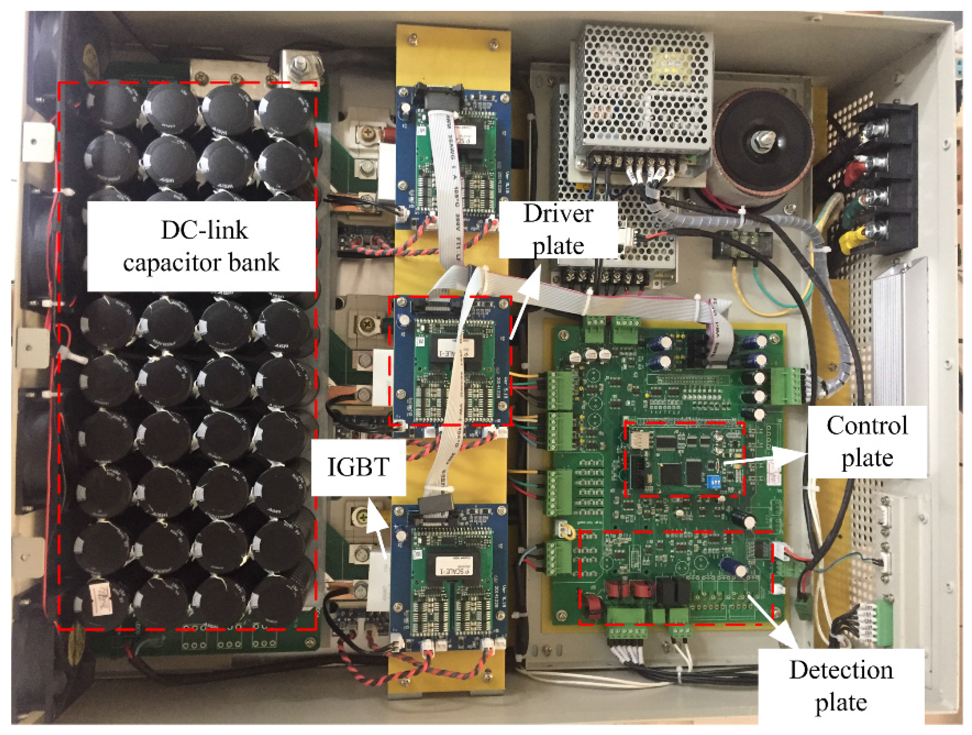
Figure 8.
Waveform of DC side voltage and reactive current.

Figure 9.
SVG Waveforms of U–I relation before and after compensation (resistive–inductive load).

Figure 10.
Magnitude spectrum of current waveform when SVG working on.

Figure 11.
SVG Waveforms of U–I relation when load changing.

Figure 12.
SVG Waveforms of U–I relation before and after compensation (resistive-capacitive load).
© 2017 by the authors. Licensee MDPI, Basel, Switzerland. This article is an open access article distributed under the terms and conditions of the Creative Commons Attribution (CC BY) license (http://creativecommons.org/licenses/by/4.0/).
Share and Cite
MDPI and ACS Style
Wei, X.; Zhu, G.; Lu, J.; Li, W.; Qi, A.E. Improved Reactive Current Detection Method of SVG. Energies 2017, 10, 1374. https://doi.org/10.3390/en10091374
AMA Style
Wei X, Zhu G, Lu J, Li W, Qi AE. Improved Reactive Current Detection Method of SVG. Energies. 2017; 10(9):1374. https://doi.org/10.3390/en10091374
Chicago/Turabian StyleWei, Xueliang, Guorong Zhu, Jianghua Lu, Wenjing Li, and And Erjie Qi. 2017. "Improved Reactive Current Detection Method of SVG" Energies 10, no. 9: 1374. https://doi.org/10.3390/en10091374
Note that from the first issue of 2016, this journal uses article numbers instead of page numbers. See further details here.