A Parallel Restoration for Black Start of Microgrids Considering Characteristics of Distributed Generations


Department of Electrical Engineering, Tongji University, Shanghai 201084, China
*
Author to whom correspondence should be addressed.
Energies 2018, 11(1), 1; https://doi.org/10.3390/en11010001
Submission received: 7 November 2017
/
Revised: 7 December 2017
/
Accepted: 15 December 2017
/
Published: 21 December 2017
(This article belongs to the Special Issue Emerging Power Electronics Technologies for Power Systems and Machine Drives)
Abstract
:The black start capability is vital for microgrids, which can potentially improve the reliability of the power grid. This paper proposes a black start strategy for microgrids based on a parallel restoration strategy. Considering the characteristics of distributed generations (DGs), an evaluation model, which is used to assess the black start capability of DGs, is established by adopting the variation coefficient method. Thus, the DGs with good black start capability, which are selected by a diversity sequence method, are restored first in parallel under the constraints of DGs and network. During the selection process of recovery paths, line weight and node importance degree are proposed under the consideration of the node topological importance and the load importance as well as the backbone network restoration time. Therefore, the whole optimization of the reconstructed network is realized. Finally, the simulation results verify the feasibility and effectiveness of the strategy.
1. Introduction
In recent years, due to the gradual depletion of fossil fuel and increasing environmental pressure, the distributed power generation technology of renewable energy has been rapidly developing. As an important application form of distributed generation (DG), microgrids have received widespread attention [1,2]. Although the reliability of microgrids has been greatly improved, all kinds of uncertainties resulting in blackout are inevitable [3], so the research on the black start of microgrids in islanding mode has important significance for speeding up the restoration process of microgrids and reducing outage loss.
Black start of microgrids refers to the technology when blackout, which is caused by external or internal fault, occurs in microgrids, and the restoration process does not rely on large power systems or other microgrids, but on the distributed generations with black start capability driving other DGs without such capability and gradually expanding the scope of restoration [4,5]. The black start of microgrids includes three stages, namely, DG restoration, network reconfiguration and load restoration. As the connecting stage of the restoration process, network reconfiguration is to restore the DGs’ connection to the network and generate electricity again as fast as possible. It lays a foundation for the restoration of load by restoring important nodes and reconstructing the backbone network with key lines [6,7,8]. In conventional power systems, there are two types of black start strategies: the build-up strategy and build-down strategy. The first one is that the high voltage grid is energized first and then used to energize the lower voltage systems, while the second one starts from individual generating units with black start capability and critical loads and synchronizes them later [9]. This paper gives a new explanation to two strategies of microgrid restoration, namely, serial restoration and parallel restoration. Serial restoration is when the blackout occurs, one of the DGs with good black start capability within the blackout area is selected and restored first, providing stable voltage and frequency to energize other DGs. This strategy gives priority to the reconstruction of backbone networks, and gradually expands the scope of restoration under the balance of active power. Parallel restoration is when the blackout occurs, DGs with good black start capability within the blackout area are restored in parallel and the DGs without black start capability nearby are energized later. The scope of restoration is gradually expanded under the balance of active power. The backbone network is reconstructed through the interconnection of the restored area.
At present, the black start of power system is studied widely, but the focus is mainly on the traditional bulk power grid. The research on the black start of microgrids is still in an early stage. Ref. [10] analyses the feasibility of selecting microgrids as black start power. It adopts the Dijkstra algorithm to search for the extended black start paths. However, it mainly focuses on the traditional bulk power grid with DGs and microgrids in grid-connected mode. Ref. [11] studies the categories of micro sources and their control strategies. It presents a black start strategy based on the serial restoration strategy with long restoration time. Ref. [12] tackles the problem with black start restoration sequences to be used for microgrids after a blackout occurs. The control strategies are analyzed and the identification of the set of rules and conditions are derived. Ref. [13] establishes a dynamic model for micro sources and inverters, respectively. It proposes a restoration strategy for microgrids’ black start and subsequent islanded operation based on multi-agent technology. The identification of the set of rules and conditions are derived and evaluated by numerical simulations. Ref. [14] verifies the feasibility of adopting a hierarchical architecture of a multi-agent system in microgrid operation. However, in the above references, the focus is mainly on the control of the black start process and pays little attention to the number of DGs, loads and lines.
This paper proposes a black start strategy for microgrids based on parallel restoration strategy. Compared to the serial restoration strategy, which involves the charging of network and the reconstruction of backbone network, the parallel restoration, which divides the system into some small systems and restores them in parallel, can shorten the restoration time and reduce the outage loss. In consideration of the characteristics of DGs, the model of DGs is established to evaluate the black start capability, adopting the diversity sequence method to select the DGs with good black start capability. The black start DGs adopt a constant voltage and constant frequency control (V/f control) strategy to provide reference voltage and frequency to the DGs to be restored. Line weight and node importance degree are introduced as the indices to select the recovery path. The paths from the restored power supply area to the DGs to be restored are searched until all DGs have been interconnected to form the backbone network. Subsequently, the scale of the network structure is gradually expanded until the microgrids is fully restored to normal operation. Compared to the serial restoration strategy, this strategy focuses on the parallel restoration of DGs, which can not only ensure the synchronization of the whole network restoration, but also take into consideration the hierarchy of the restoration of the microgrids. This parallel restoration strategy is a combination of complex network theory and power system analysis. It also provides a new thought for the black start of microgrids.
The organization of this paper is as follows: Section 2 analyzes the characteristics of DGs and proposes a black start capability evaluation model of DGs based on a variation coefficient method. The parallel restoration strategy for microgrid reconfiguration is explained in detail in Section 3. Simulation results to prove the effectiveness of the strategy are demonstrated in Section 4. Section 5 concludes the paper.
2. Characteristic Analysis of DGs and Evaluation Model of DGs’ Black Start Capabilities
2.1. Characteristics of DGs
The difference between conventional power system and microgrids mainly comes from the difference between DGs and conventional thermal power generating units, so the microgrids cannot directly copy the black start strategy of conventional power system. Therefore, it is necessary to take into account the characteristics of DGs when developing the black start strategy of microgrids. Compared with thermal power generating units, DGs have the following unique characteristics:
(1) The output power of DGs is intermittent
Conventional thermal power generating units can adjust its output according to the generation plan while the output of renewable energy source is intermittent. Taking wind power and photovoltaic power as an example, the output will fluctuate with the change of wind speed and light intensity.
(2) DGs have various control strategies
Most DGs are not suitable for a direct connection to the grid, thus the power electronic interface is needed. DGs’ control strategies are mainly inclusive of constant power control (PQ control), V/f control, droop control, virtual synchronous generator and so on. Different control strategies are adopted according to the specific situation [15,16,17].
(3) DGs start up without external power supply
Conventional thermal power generating units with high power loads need starting power supply. Relatively, DGs have the ability to operate independently as DGs mainly rely on the natural conditions around. Taking wind turbine as an example, when wind speed reaches the minimum requirement, electricity is automatically generated without external power.
(4) DGs start up free from the starting time constraints
The startup of conventional thermal power generating units is divided into hot start, warm start and cold start by the cylinder temperature. In order to protect the cylinder from the thermal stress caused by large temperature difference, the cylinder temperature needs to be controlled, leading to a longer starting time of warm start and cold start. Therefore, the black start strategy of the conventional power system needs to consider the starting time constraints of thermal power generating units. In contrast, DGs are free from the starting time constraints, so the recovery time of microgrids is shorter.
(5) DGs can improve power quality by using energy storage devices
Energy storage devices can avoid large frequency and voltage deviations and provide stable voltage and frequency for microgrids by injecting (or absorbing) active power into the microgrids proportionally to the frequency deviation [18], so V/f control mode is adopted for the DGs with storage devices, while the output power of DGs without energy storage devices is intermittent, and DGs without energy storage devices cannot generate electricity in accordance with the load demand. Therefore, PQ control strategy is usually adopted.
2.2. Black Start Capability Evaluation Model of DGs Based on Variation Coefficient Method
The black start capability of DGs is that the black start process does not rely on external power, but on DGs own starting power sources to start up and provide stable power supply for a certain number of loads. Considering the characteristics of DGs, the black start capability evaluation model of DGs based on variation coefficient method is established in this paper. It selects DGs’ real-time output power, starting time, load capacity, variable voltage and variable frequency capability (VVVF capability) and State of Charge (SOC) of the DGs with energy storage devices as the indices to evaluate the black start capability. The variation coefficient method is adopted to assign weight to each index and DGs with good black start capability are selected by diversity sequence method.
Among the above evaluation indices, the reason why real-time output power should be taken into consideration is that restoring DGs with high real-time output power first can generate more electricity in a short time, so as to guarantee power supply to more loads, which is beneficial to the restoration of the network. As the DGs’ capacity depends on ambient condition, its capacity does not mean the real-time output power, but the maximum capability of its output power, which is different from conventional thermal power generating units. The capacity of thermal power generating units is the maximum of real-time output power controlled by input fuel. Since restoring DGs with short starting time can accelerate the whole restoration process, the starting time of DGs is an important index to be considered. Because restoring DGs with better load capacity can feed more loads during the same amount of time, taking into account the load capacity of DGs is needed. DGs with good VVVF capability can provide the network with voltage and frequency reference, making it more stable at the initial stage of black start. DGs with higher SOC can maintain stable power output for a longer time, which is conducive to maintain the stability of network.
The variation coefficient [19], as an objective weighting method, assesses the weight of each index by calculating the index data. According to the variation coefficient method, indexes with a large difference can indicate the quality of the evaluated objects and reflect objective information of the change of index data, so the index is given more weight. The specific steps of the variation coefficient method are as follows:
(1) establish evaluation matrix
Let there be n objects and m evaluation indices, the evaluation index vector of the object i is denoted as Xi = [xi1, xi2, xi3, …, xim], and thus the evaluation matrix is denoted as X = [xij]n×m. The index weight of index j is expressed by ωj, and then the index weight vector is ω = [ω1, ω2, …, ωm]T.
(2) normalize the indices
In order to eliminate the effect of index dimension, it is necessary to normalize the original index value.
It is better for a positive index, which is also called as “efficiency” index, to have a larger index value:
Negative index, which is also called “cost” index, should have a smaller index value:
In Equations (1) and (2), i = 1, 2, …, n; j = 1, 2, …, m; is the normalized value of the index j of the object i.
(3) calculate the weight of index
After normalizing each index, the average value and standard deviation of each index are calculated by Equations (3) and (4):
The variation coefficient of each index is calculated by Equations (5):
where Vj is the variation coefficient of the index j; is the average value of the index j; and is the standard deviation of the index j.
Then, the weight of each index is:
(4) obtain comprehensive score
The product of evaluation matrix X and weight vector ω is the comprehensive score vector G of each object:
After scoring DGs by this comprehensive evaluation method, the DGs with good black start capability are further screened out by the diversity sequence method and selected to be restored first.
3. Index and Model of Microgrid Reconstruction Based on Parallel Restoration
The main purpose of the network reconfiguration is to reconstruct the backbone network in the shortest time by restoring the important nodes and key lines, so that the DGs to be restored can be connected to the network again. This paper introduces the line weight and node importance degree as the indices to select the recovery path. Line weight is evaluated by line operation time, and node importance degree is evaluated by combining the importance of node topology and nodal load. It provides guidance for the reconstruction of network.
3.1. Line Weight
In the black start process of conventional power systems, the overvoltage problem may easily occur when charging for the transmission lines without load. The long-distance high-voltage transmission line contains the distributed capacitance and inductance. The phase difference between inductive voltage and capacitive voltage is 180°. The capacitive reactance will raise the terminal voltage of transmission line while the inductive reactance will drop the terminal voltage of transmission line. As the capacitive reactance is larger than inductive reactance, the capacitive current will flow through the line, so the capacitance effect of non-loaded line may cause the overvoltage problem. Charging capacitor on the line can preferably reflect the risk of overvoltage, so it is often used to weigh the lines in the black start of conventional power systems. However, the scale of microgrids is small, the distributed capacitance and inductance are much smaller, and overvoltage problem is less likely to occur. In order to shorten the restoration time, the line operation time is used to weigh the lines when selecting the recovery path [20]. The path with short operation time is selected to speed up the restoration process. According to the experience of operator, the optimistic operation time D, pessimistic operation time A and the most probable time M are determined. The actual operation time of line is a beta distribution between D and A [21,22], so the expectation E(ti) and variance of operation time ti of line i are defined as:
where E(ti) is the expectation of operation time of line i, is the variance of operation time of line i, D is the optimistic operation time, A is the pessimistic operation time and M is the most probable operation time.
In this paper, the operation time is random. It is easily proved that for two random numbers a and b, if E(a) > E(b), then Pr(a > b) ≥ Pr(a < b). Therefore, the expectation of the operation time is selected as the weight of recovery path.
3.2. Node Importance Degree
This paper evaluates the node importance degree mainly in two aspects: the electrical connection between nodes, known as the importance of node topology, and the factors of nodes themselves, known as the importance of nodal load. Taking the above two aspects into consideration makes the evaluation of node importance degree more objective.
For the importance of node topology, node betweenness is used to evaluate it quantitatively in this paper. The concept of betweenness was proposed by Freeman in 1979, which reflects the core role of the node in network [23]. The node with larger node betweenness plays a more important role in network, and removing the node with larger betweenness value will make the distance between large numbers of nodes pairs longer. This paper defines node betweenness as the proportion of the shortest paths via the node among all the shortest paths, and the betweenness is expressed as:
where is the betweenness of the Node k; is the number of the shortest paths between any two nodes in a network via Node k; is the number of the shortest paths between any two nodes in a network; and is a set of all nodes in a network.
During the black start process, the re-energization of a certain number of loads is mainly to ensure the stable operation of the network and keep the system voltage within the allowable range. As the re-energization of loads needs all aspects of coordination and certain operation time, a small number of nodes with important loads should be restored. For the importance of nodal load, load capacity and load level are mainly considered in this paper. Loads are generally divided into three levels [24]. For the nodes with the same number of loads, the higher the load level is, the more outage loss and the greater the importance of load will be. Therefore, the importance of nodal load is defined as:
where is the load importance of node k; is the load weight of node k; and is the load capacity of the node k.
By adjusting the value of load weight , the nodes with important loads can be restored first. This paper assumes that the weight of the first level load is 1, while the second is 0.3 and the third is 0.08.
Since it is not possible to directly compare betweenness and load importance due to the dimension difference, normalization is essential. Therefore, the maximum value of node betweenness and nodal load importance are selected as their reference value, respectively. The node importance is defined as:
where Wk is the importance degree of node k; Bk is the betweenness of node k; Bbase is the reference value of the node betweenness; Lk is the load importance of node k; Lbase is the reference value of load importance; and are the proportional coefficient and they are used to adjust the relative importance of Bk and Lk; + = 1. Considering that restoring important nodes with greater betweenness is conducive to speeding up the reconstruction of the network, this paper takes = 0.6, = 0.4.
3.3. Optimization Model of Recovery Path
After screening out the DGs for black start, the next step is to select a suitable recovery path for the DGs to be restored.
3.3.1. Objective Function
The recovery path consists of a number of nodes and lines. In order for the recovery path to restore more important nodes and use less time, this paper considers the importance of node topology, the importance of load and the recovery time of the network when selecting the recovery path. Therefore, the optimization objective function of the recovery path is defined as:
where s and e are the start node and end node of the recovery path, respectively; is the average importance of the nodes to be recovered in the recovery path; and is the sum weight of the paths to be restored.
In the objective function (13), the numerator is the average value of the importance degree of nodes to be restored in recovery path. The larger the numerator is, the more “efficient” the recovery path will be. The reason for selecting the average value and not the sum value of the importance degree of nodes to be restored in the recovery path is due to the fact that selecting a longer recovery path that passes more important nodes may raise the risk of operation failure. The denominator is the sum weight of the paths to be restored, which stands for the “cost” of the recovery path. The larger the value of the denominator, the greater the restoration time. Selecting the recovery path with maximum f can restore as many important nodes as possible by less line operation, which is constructive to the reconfiguration of a backbone network.
3.3.2. Constraint Condition
The recovery process needs to satisfy some constraints. The explanation is as follows:
(1) DGs output constraint
where is the set of all the DGs in the network; and are the active power and reactive power of DG i, respectively; and are the lower and upper bounds of the active power of DG i, respectively; and are the lower and upper bounds of the reactive power of DG i, respectively.
(2) Node voltage constraint
where is the set of all nodes in the network; is the voltage magnitude of Node i; and are the lower and upper bounds of the voltage magnitude of Node i, respectively.
(3) Line constraint
where is the set of all lines in the network; is the active power flowing in the Line i; and .
is the maximum active power of Line i.
(4) Node power balance constraint
where and are the active power and reactive power injected to Node i, respectively; and are the voltage of Node i and Node j, respectively; is the conductance between Node i and Node j; is the susceptance between Node i and Node j; and is the voltage phase difference between Node i and Node j.
In Equation (18), the equals the output active power of DGi minus active power of the load on node i. The result of Equation (18), which can be adjusted by controlling the loads of node i, should be 0 to maintain stable frequency of system. In Equation (19), the equals the output active power of DGi minus reactive power of load on node i. The result of Equation (19), which can be adjusted by using inductive compensation equipment, should be 0 to maintain stable voltage of the system.
3.3.3. Stability
During the restoration process of microgrids, due to the weakness of the backbone network, a stability problem may occur that affects the restoration of microgrids [25]. The specific analysis is as follows:
(1) Transient stability of the small independent system
The parallel restoration of microgrids black start will inevitably create stable operation of a number of discrete and independent small systems. It is necessary to conduct a stable analysis of the small systems that run independently during the initial recovery period. The short-circuit fault is generally used to analyze a small system’s anti-disturbance capability. According to the “Guide on Security and Stability for Power System” [26], the transient stability of a small system in the initial stage of black start is usually investigated as the single fault of a single-phase grounding fault.
(2) The stability of closed loop and grid-connected
The parallel restoration of microgrids will face the synchronization problem when discrete and independent small systems connect to the backbone network, and it will inevitably generate a combined loop current, which will affect the safety and stability of grid operation. The main cause of the loop current is that the voltage difference of the bus or line on both sides of the loop switches produces the circulating current. The reactive power compensation device can be added in the appropriate position to adjust the distribution of reactive power flow in the network, thus changing the voltage at both ends of the loop and reducing the influence of the closed loop current on the system.
3.3.4. Communication
The microgrids is controlled by a microgrid central controller (MGCC) installed in the low voltage substation. The MGCC should exchange information with the local distribution management system (DMS), which needs to be enhanced with new features related to the microgrid operation. Communication between MGCC and DMS includes information related to upstream grid status and economic issues for an efficient management of the microgrids. At a second hierarchical control level, controllers located at loads or at groups of loads (smart switch) and controllers located at DG or microsource controller (MC) exchange information with the MGCC and control local devices.
During normal operation, the MGCC periodically receives information from the smart switches and MCs about consumption levels and power generation, storing this information in a database. After a general blackout, the MGCC will perform service restoration based on the information stored in a database about the last microgrid load scenario by controlling a sequence of actions of smart switches and MCs.
3.4. Parallel Restoration Strategy for Microgrid Reconfiguration
In summary, the steps of the parallel restoration strategy are as follows:
Step 1: Read in the parameters of each DG in microgrids, inclusive of real-time output power, starting time, load capacity, the VVVF capability and the SOC of the energy storage device on DG. For the wind turbine and photovoltaic without energy storage, its SOC index is 0; for a micro gas turbine, assuming that the gas is sufficient to maintain stable output power, its SOC index is 1. The black start capability score of each DG can be evaluated based on the evaluation model of black start capability.
Step 2: According to the comprehensive score of black start capability, DGs with good black start capability are selected via a diversity sequence method to be restored first.
Step 3: Read in the network parameters of microgrids and weigh the line by its operation time.
Step 4: Construct a weighted adjacency matrix in accordance with the weighted network. The number of all the shortest paths via each node in the network is calculated through the Betweenness–Centrality algorithm and the betweenness of each node is finally determined. The importance of nodal load is calculated by Equation (11). Finally, the importance degree of each node is calculated by Equation (12). Since the restoration of the power-supply node is more important in the process of network reconfiguration, this paper selects the maximum value of the node importance degree max Wk as power-supply node importance degree.
Step 5: Centered on the DGs screened out for black start, parallel restoration is synchronous. Search the paths from a power supply area to DGs to be restored and select the path with maximum f value as the recovery path. Black start DGs adopt a V/f control strategy to provide stable voltage and frequency. DGs to be restored are connected to the grid in PQ control mode. Once the connection between black start DGs is set up, DGs with a high black start score adopts a V/f control strategy to provide stable voltage and frequency, while the ones with low scores switch to PQ control mode.
Step 6: In the restoration process, it is necessary to supply a proper number of loads to ensure the stable operation of the network; in addition, it is necessary to test whether the DGs’ output constraints (14) and (15), node voltage constraint (16), line constraint (17), and node power balance constraints (18) and (19) are satisfied. If a line operation fails in the restoration process, return to step 5 on the basis of the restored lines and nodes and select a new recovery path.
Step 7: Repeat steps 5 and step 6 until all the DGs can be interconnected to form the backbone network. Then, energize the rest loads until the black start process succeeds and microgrids are fully restored to normal operation.
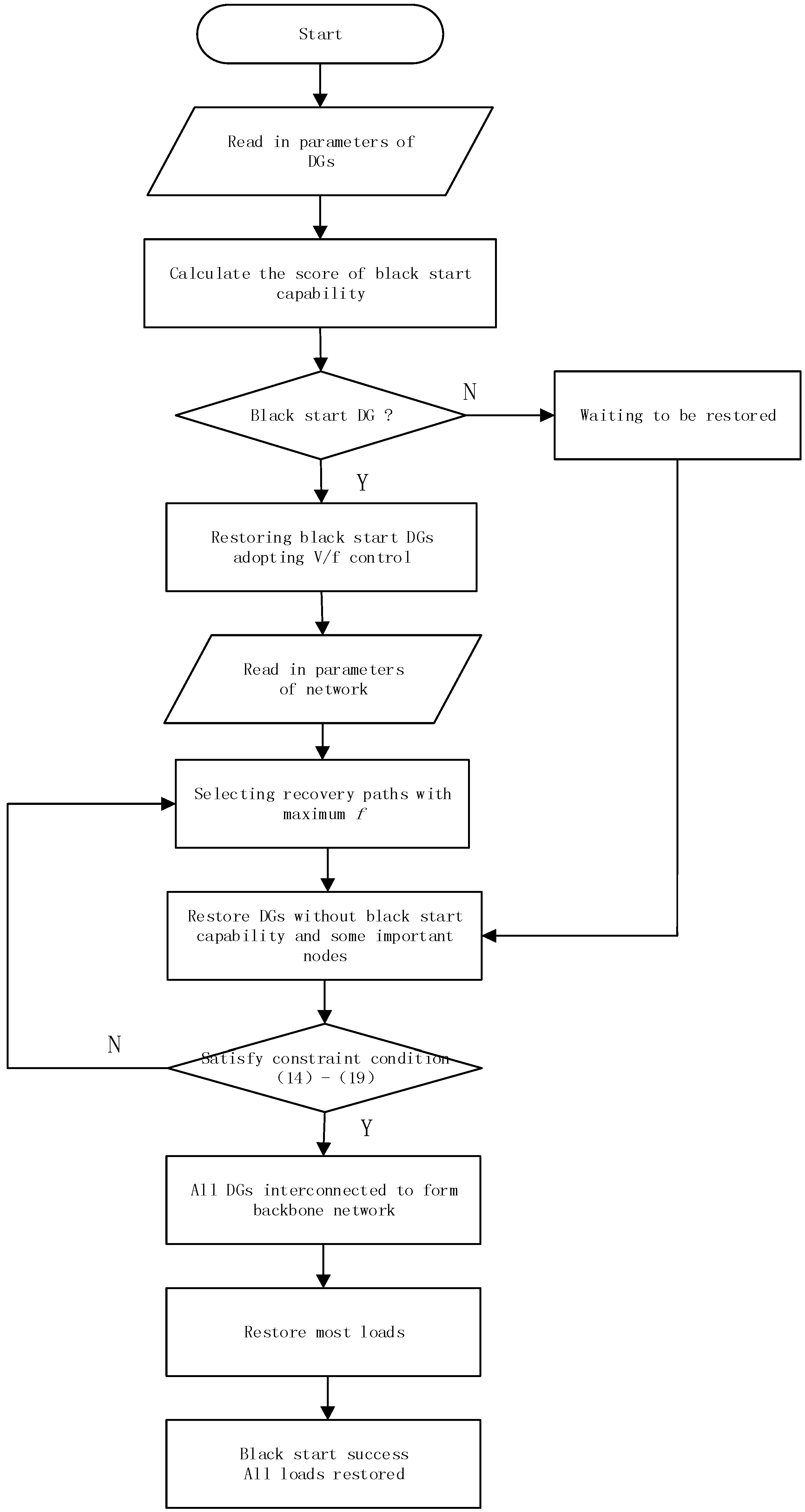
The flow chart of this restoration strategy is shown in Figure 1.
4. Numerical Results
According to Ref. [27], a modified Institute of Electrical and Electronics Engineers (IEEE) 30-bus microgrid system is selected as an example in this paper, as shown in Figure 2. The system consists of seven DGs, 30 load nodes and 41 lines. The feasibility of the parallel restoration strategy proposed in this paper is verified by MATLAB (R2013b (8.2.0.701), The MathWorks, Inc., Natick, MA, USA) simulation.
- (1)
- The assumptions of the simulation are as follows: the real-time output power (Output), starting time, VVVF capability, load capacity, and SOC of each DG are shown in Table 1.
- (2)
- The expectation E(t) of operation time for each line is shown in Table 2. For each load, 1 min is needed for the transient regulation process.
- (3)
- Considering that restoring important nodes with greater betweenness is conducive to speeding up the reconstruction of the network, this paper takes α = 0.6, β = 0.4.
- (4)
- By adjusting the value of load weight , the nodes with important loads can be restored first. This paper assumes that the weight of the first level load is 1, while the second is 0.3 and the third is 0.08.
According to Section 2.2, the black start capability evaluation model of each DG is established and the comprehensive score of DGs’ black start capability (Score) is obtained, which is shown in Table 3. DGs are divided into two types via a diversity sequence method, namely, black start DGs and DGs without black start capability. DGs that are screened out for black start are restored first. The classification results via diversity sequence method and the control strategy of each DG are shown in Table 3.
From Table 3, although DG3 is a wind turbine with energy storage device and it can provide power for a certain number of loads, the SOC of its energy storage device is too low to provide stable output power for a long time, so DG3 is not suitable as a black start power source.
The number of all the shortest paths via each node in the network is calculated through the Betweenness–Centrality algorithm, and then the node betweenness is calculated. The normalized value of node betweenness is shown in Table 4. The larger the betweenness is, the more important the node is in the network. Combined with the importance of nodal load, the importance degree of each node is further calculated and shown in Table 5. The maximum value of node importance degree is selected as power-supply node importance degree. The larger the node importance value is, the greater the number of shortest paths that are passed via this node and the more important loads this node has. Restoring the nodes with large node importance values can speed up the process of restoration and reduce the outage loss.
Black start power sources DG2, DG22, DG27 are the first to be restored, while DGs without black start capability wait to be restored. Centered on the black start power source DGs, DGs without black start capability are restored in parallel. Among all the paths from black start DGs to DGs to be restored, the ones with maximum f value are selected, which are shown in Table 6. The larger f value is, the more important nodes the recovery path has and the less the “cost” of the recovery path.
The paths with the maximum f value are selected as the recovery path from black start DGs to DGs to be restored, namely the recovery paths are:
2 → 1, 2 → 1 → 3, 22 → 24 → 23, 22 → 24 → 23 → 15 → 12 → 13.
However, DGs have not been interconnected. It is necessary to restore part of the lines to make all DGs interconnected to form the backbone network. A further search for the paths with maximum f value among the black start power sources, namely the recovery paths are:
2 → 6 → 10 → 22, 27 → 28 → 6.
The restoration strategy is shown in Figure 3, in which the solid lines are the restored lines while the dotted lines are the ones to be restored.
From Figure 3, all DGs and some important nodes have been restored. DGs have been interconnected to form a stable backbone grid. There are 13 nodes and 12 lines restored during the interconnection of DGs. Among the nodes that are not restored, only node 11, node 19 and node 26 are two lines away from the backbone network, the rest are all one line away from the backbone network. The recovery paths have a good coverage for the microgrids. The rest of the nodes and lines can be restored rapidly at later stages.
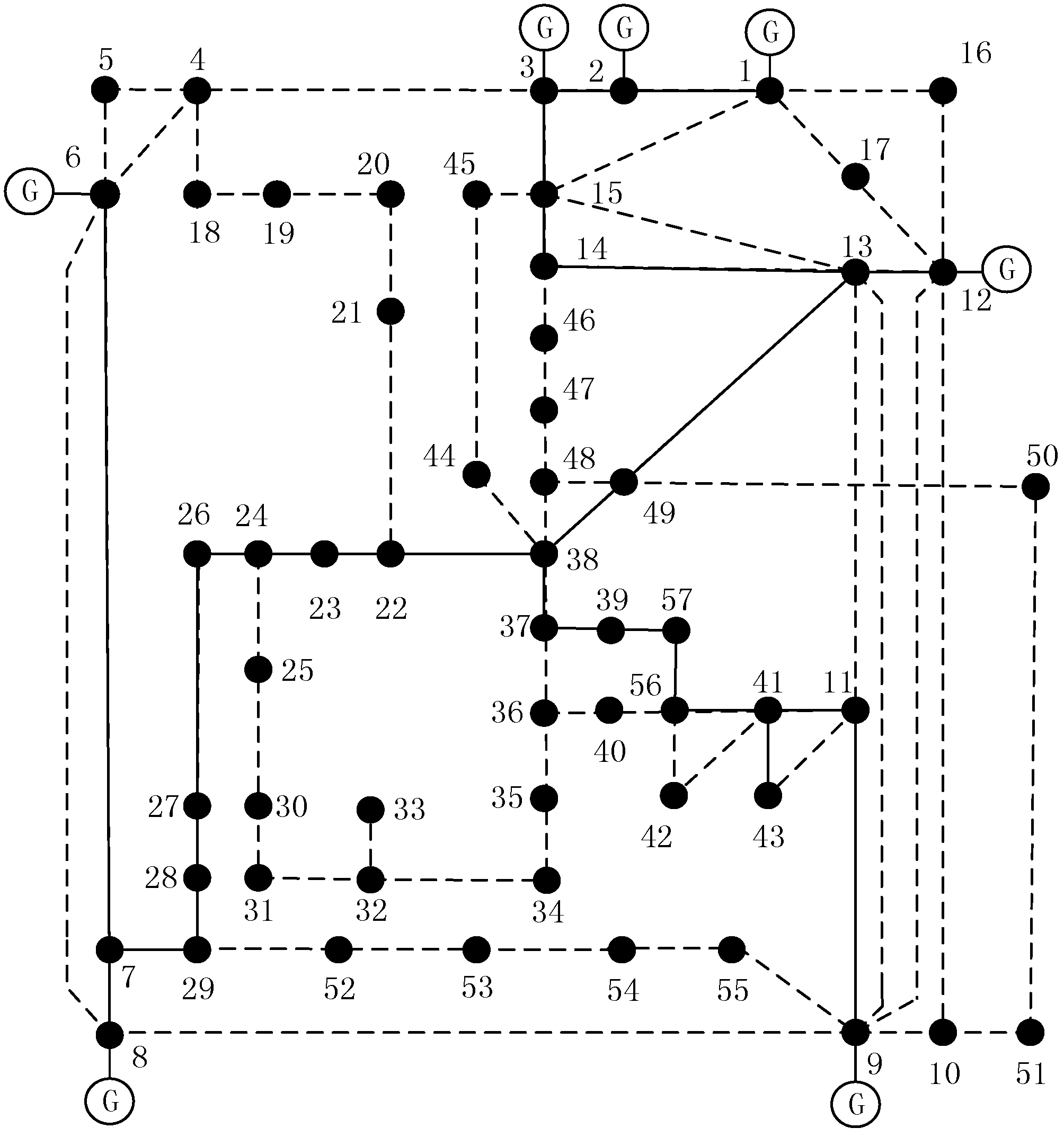
In order to further verify the effectiveness of the parallel restoration strategy, the same work is done for the IEEE57-bus microgrid system [28], which contains seven DGs, 57 nodes and 80 lines. Its structure is shown in Figure 4.
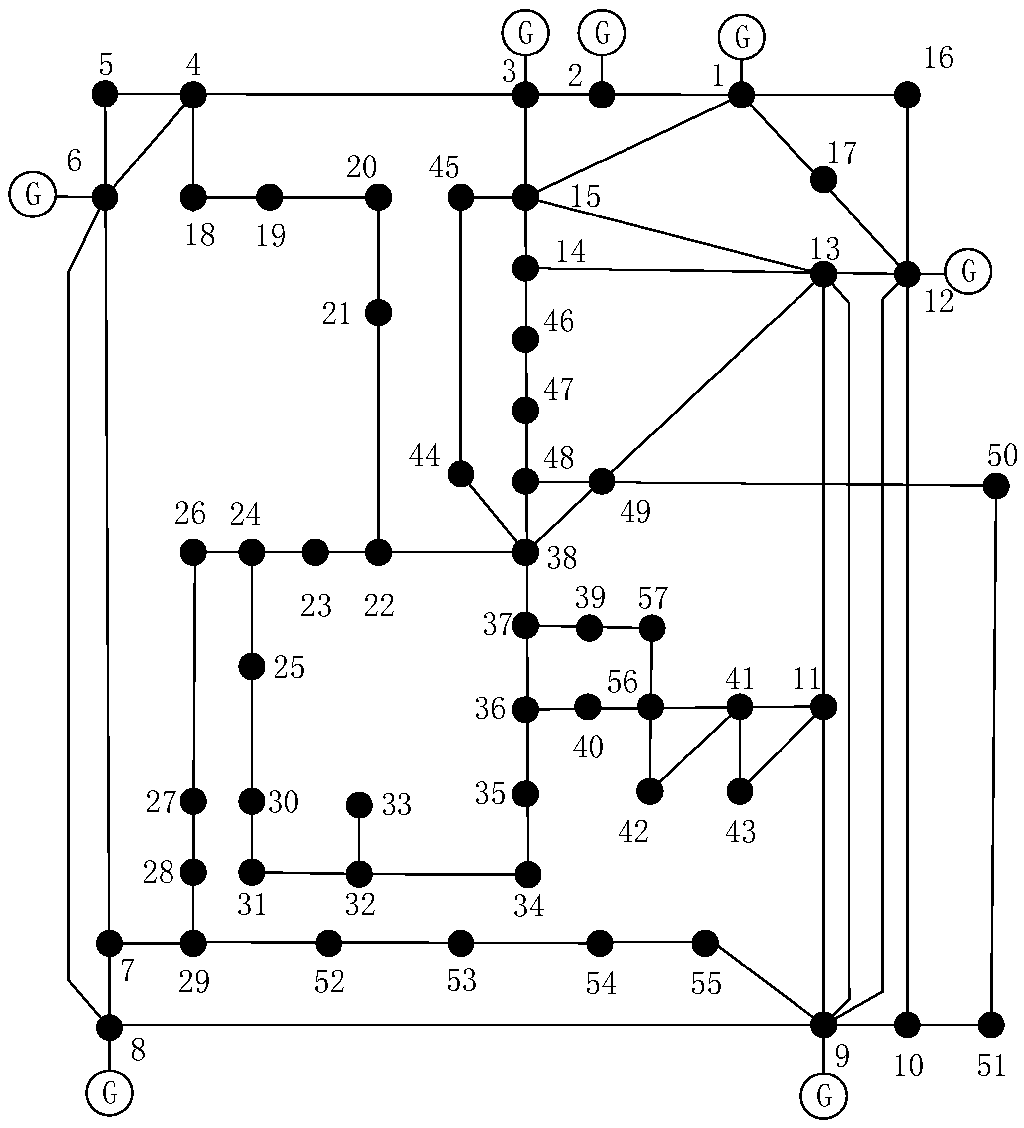
According to the parallel restoration proposed in this paper, firstly the black start capability score of each DG is evaluated based on the parameters of DGs. DG2, DG6 and DG12 are selected as the black start DGs accordingly. Then, above black start DGs are restored, adopting a V/f control strategy to provide reference voltage and frequency. After that, the paths from the power supply area to DGs to be restored are searched and paths with maximum f value are selected as the recovery paths. Although the path 1 → 2 → 3 → 4 → 6 → 8 → 9 → 12 is the shortest path to restore all DGs and form the backbone network, the recovery path contains a small number of shortest paths, which means restoring a few important nodes with large betweenness values, making the f value of the recovery path low. Moreover, the backbone network that is formed by this recovery path is away from most nodes in the network, which will take a longer time in the restoration of the rest of the nodes. Therefore, it is not suitable to be selected as the recovery path. The recovery paths with maximum f values for the DGs to be restored are shown as follows: DG1: 2 → 1, DG3: 2 → 3, DG8: 6 → 7 → 8, DG9: 12 → 13 → 49 → 38 → 37 → 39 → 57 → 56 → 41 → 11 → 9. It is necessary to restore part of the lines to make all DGs interconnected to form the backbone network. A further search for the paths with maximum f values among the black start power sources, namely the recovery paths are: 13 → 14 → 15 → 3 and 7 → 29 → 28 → 27 → 26 → 24 → 23 → 22 → 38. The final restoration strategy is shown in Figure 5, in which the solid lines are the restored lines while the dotted lines are the ones to be restored.
There are 26 nodes restored during the interconnection of DGs. The top five nodes with the largest node importance degree values are all restored. Among the rest 21 nodes that are not restored, except for node 32, which is four lines away from the backbone network and node 33, which is five lines from the backbone network, 84.2% of the rest nodes are no more than two lines from the backbone network. The backbone network does not have redundant nodes and lines, providing the prerequisite and guarantee for the restoration of the rest load in the next step.
5. Conclusions
This paper proposes a parallel restoration strategy for microgrids’ black start. First, the evaluation model of DGs’ black start capability is established by a variation coefficient method, and the comprehensive score of DGs’ black start capability is obtained. DGs with good black start capability are screened out by a diversity sequence method. Then, under the constraints of DGs and network, the importance degree of nodes and line operation time are introduced as the indices to select the recovery path, comprehensively considering the importance of node topology, the importance of load and the recovery time of the network. The black start power source adopts a V/f control strategy to provide reference voltage and frequency to DGs to be restored in parallel. Among all the paths from DGs for a black start to DGs to be restored, the ones with the maximum optimization objective function value are selected as the recovery paths until the DGs can be interconnected to form the backbone network; finally, the feasibility of the proposed strategy is verified by a modified IEEE 30-bus microgrid system and the IEEE 57-bus microgrid system.
Acknowledgments
This work was supported in part by the Fundamental Research Funds for the Central Universities of China (0800219375).
Author Contributions
The paper was a collaborative effort among the authors. Jing Wang performed the simulation, analyzed the data, and wrote the paper. Longhua Mu provided critical comments. Fan Zhang and Xin Zhang supervised the related research work.
Conflicts of Interest
The authors declare no conflict of interest.
Nomenclature
| List of Abbreviations | |
| DG | Distributed generation |
| VVVF | Voltage modulation and frequency modulation |
| SOC | State of charge |
| MGCC | Microgrid central controller |
| DMS | Distribution Management System |
| MC | Microsource controller |
| List of Symbols | |
| D | Optimistic operation time |
| A | Pessimistic operation time |
| M | Most probable time |
| Expectation of operation time | |
| PR(n) | Probability of event n |
| Variance of operation time | |
| B | Betweenness |
| N | Number of shortest paths |
| f | Objective function value |
| L | Load importance |
| W | Importance degree |
| P | Active power |
| Q | Reactive power |
| U | Voltage |
| α β | Proportional coefficient |
| C | Weight of the paths |
| G | Conductance |
| S | Susceptance |
| Voltage phase difference | |
| List of Superscripts | |
| max | Maximum value of variable |
| min | Minimum value of variable |
| List of Subscripts | |
| i, j, k | Node number |
| s | Start node |
| e | End node |
References
- Solanki, A.; Nasiri, A.; Bhavaraju, V.; Familiant, Y.L.; Fu, Q. A new framework for microgrids management: Virtual droop control. IEEE Trans. Smart Grid 2016, 7, 554–566. [Google Scholar] [CrossRef]
- Iqbal, F.; Siddiqui, A.S. Optimal configuration analysis for a campus microgrids—A case study. Prot. Control Mod. Power Syst. 2017, 2, 23. [Google Scholar] [CrossRef]
- Ananda, S.A.; Gu, J.C.; Yang, M.T.; Wang, J.M.; Chen, J.D.; Chang, Y.R.; Lee, Y.D.; Chan, C.M.; Hsu, C.H. Multi-Agent system fault protection with topology identification in microgrids. Energies 2016, 10, 28. [Google Scholar] [CrossRef]
- Li, C.; He, J.; Zhang, P.; Xu, Y. A novel sectionalizing method for power system parallel restoration based on minimum spanning tree. Energies 2017, 10, 948. [Google Scholar] [CrossRef]
- Thale, S.; Agarwal, V. A smart control strategy for the black start of a microgrids based on PV and other auxiliary sources under islanded condition. In Proceedings of the IEEE Photovoltaic Specialists Conference, Seattle, WA, USA, 19–24 June 2011; pp. 2454–2459. [Google Scholar]
- Ancona, J.J. A framework for power system restoration following a major power failure. IEEE Trans. Power Syst. 1995, 10, 1480–1485. [Google Scholar] [CrossRef]
- Adibi, M.M.; Fink, L.H. Power system restoration planning. IEEE Trans. Power Syst. 1994, 9, 22–28. [Google Scholar] [CrossRef]
- Adibi, M. Power System Restoration a Task Force Report; Wiley-IEEE Press: Hoboken, NJ, USA, 2009; pp. 3–9. [Google Scholar]
- Pham, T.T.H.; Besanger, Y.; Hadjsaid, N.; Ha, D.L. Optimizing the re-energizing of distribution systems using the full potential of dispersed generation. In Proceedings of the IEEE Power Engineering Society General Meeting, Montreal, QC, Canada, 18–22 June 2006. [Google Scholar]
- Wu, Z.; Zhang, D.; Lin, X. Research on the Extended Black-Start Scheme of Power System with Microgrid. IJREAT Int. J. Res. Eng. Adv. Technol. 2016, 4, 203–215. [Google Scholar]
- Xu, Z.; Yang, P.; Zheng, Q.; Zeng, Z. Study on black start strategy of microgrids with PV and multiple energy storage systems. In Proceedings of the IEEE International Conference on Electrical Machines and Systems, Pattaya, Thailand, 25–28 October 2016; pp. 402–408. [Google Scholar]
- Moreira, C.L.; Resende, F.O.; Lopes, J.A.P. Using Low Voltage MicroGrids for Service Restoration. IEEE Trans. Power Syst. 2007, 22, 395–403. [Google Scholar] [CrossRef]
- Cai, N.; Xu, X.; Mitra, J. A hierarchical multi-agent control scheme for a black start-capable microgrids. In Proceedings of the IEEE Power and Energy Society General Meeting, Detroit, MI, USA, 24–29 July 2011; pp. 1–7. [Google Scholar]
- Lopes, J.A.P.; Moreira, C.L.; Madureira, A.G.; Resende, F.O.; Wu, X.; Jayawarna, N.; Zhang, Y.; Jenkins, N.; Kanellos, F.; Hatziargyriou, N. Control strategies for microgridss emergency operation. In Proceedings of the IEEE International Conference on Future Power Systems, Amsterdam, The Netherlands, 18 November 2005; pp. 1–6. [Google Scholar]
- Li, D.; Zhao, B.; Wu, Z.; Zhang, X.; Zhang, L. An improved droop control strategy for low-voltage microgridss based on distributed secondary power optimization control. Energies 2017, 10, 1347. [Google Scholar] [CrossRef]
- Malik, S.M.; Ai, X.; Sun, Y.; Zhengqi, C.; Shupeng, Z. Voltage and frequency control strategies of hybrid AC/DC microgrids: A review. IET Gener. Transm. Distrib. 2017, 11, 303–313. [Google Scholar] [CrossRef]
- Xiao, Z.; Li, T.; Huang, M.; Shi, J.; Yang, J.; Yu, J.; Wu, W. Hierarchical MAS based control strategy for microgrids. Energies 2010, 3, 8–9. [Google Scholar] [CrossRef]
- Zhao, H.; Hong, M.; Lin, W.; Loparo, K.A. Voltage and Frequency regulation of microgrids with battery energy storage systems. IEEE Trans. Smart Grid. 2017, PP, 1. [Google Scholar] [CrossRef]
- Adibi, M.M.; Kafka, R.J.; Milanicz, D.P. Expert system requirements for power system restoration. IEEE Trans. Power Syst. 1994, 9, 1592–1600. [Google Scholar] [CrossRef]
- Zeng, S.; Wen, F.; Xue, Y.; Wu, W.; Lin, Z.; Dai, Y. Optimization of Network Reconfiguration Strategy for Power Systems Considering Operating Time Uncertainty. Autom. Electr. Power Syst. 2011, 35, 16–21. [Google Scholar]
- Adibi, M.M.; Milanicz, D.P. Estimating restoration duration. IEEE Trans. Power Syst. 1999, 14, 1493–1498. [Google Scholar] [CrossRef]
- Mota, A.A.; Mota, L.T.M.; Morelato, A. Dynamic evaluation of reenergization times during power systems restoration. In Proceedings of the IEEE/PES Transmission and Distribution Conference and Exposition: Latin America, Sao Paulo, Brazil, 8–11 November 2004; pp. 161–166. [Google Scholar]
- Brandes, U.; Borgatti, S.P.; Freeman, L.C. Maintaining the duality of closeness and betweenness centrality. Soc. Netw. 2016, 44, 153–159. [Google Scholar] [CrossRef]
- Wang, D.; Gu, X.; Zhou, G.; Li, S.; Liang, H. Decision-making optimization of power system extended black-start coordinating unit restoration with load restoration. Int. Trans. Electr. Energy Syst. 2017, 27. [Google Scholar] [CrossRef]
- Cui, Y.; Yan, G.P.; Liu, J.G. Protection performance analysis and settings during power black-start of northern Jiangsu district. In Proceedings of the IEEE China International Conference on Electricity Distribution, Nanjing, China, 13–16 September 2010; pp. 1–4. [Google Scholar]
- Zhao, Z.; Shu, Y.; Lei, X. DL755-2001 Guide on Security and Stability for Power System; China Water & Power Press: Beijing, China, 2001; pp. 1–10. [Google Scholar]
- Shahidehpour, M.; Wang, Y. Appendix C: IEEE30 Bus System Data. In Communication and Control in Electric Power Systems; John Wiley & Sons, Inc.: Hoboken, NJ, USA, 2005; pp. 493–495. [Google Scholar]
- Bhuyan, S.; Hazarika, S.; Bardalai, A. Power flow analysis on IEEE 57 bus system using MATLAB. Int. J. Eng. Res. Technol. 2014, 3, 1161–1171. [Google Scholar]
Figure 1.
Flow chart of parallel restoration strategy.

Figure 2.
Structure of 30-bus microgrids.

Figure 3.
The final restoration backbone network.
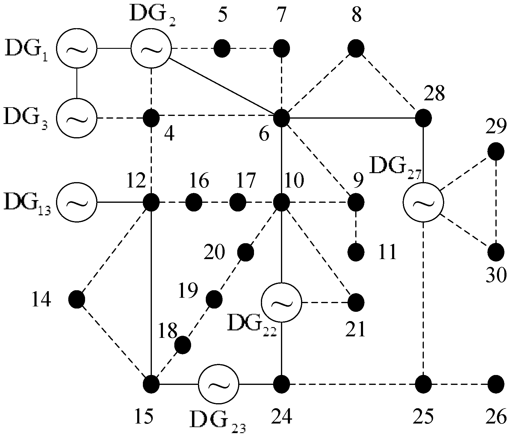
Figure 4.
Structure of 57-bus microgrids.

Figure 5.
The final restoration backbone network.

Table 1.
The parameters of distributed generations (DGs). VVVF: variable voltage and variable frequency; SOC: State of Charge; PV: photovoltaics.
Table 1.
The parameters of distributed generations (DGs). VVVF: variable voltage and variable frequency; SOC: State of Charge; PV: photovoltaics.
| DG No. | DG Type | Output (kW) | Starting Time (min) | Load Capacity (%/min) | VVVF Capability | SOC |
|---|---|---|---|---|---|---|
| 1 | wind turbines without energy storage | 400 | 3.5 | 5.20 | 50 | 0.0 |
| 2 | micro gas turbine | 1000 | 4.7 | 4.00 | 90 | 1.0 |
| 3 | wind turbines with energy storage | 650 | 4.3 | 4.29 | 70 | 0.1 |
| 13 | PV without energy storage | 650 | 4.1 | 4.31 | 45 | 0.0 |
| 22 | PV with energy storage | 900 | 4.2 | 3.89 | 75 | 0.8 |
| 23 | PV without energy storage | 450 | 3.0 | 5.14 | 40 | 0.0 |
| 27 | battery | 800 | 3.8 | 4.13 | 83 | 0.7 |
Table 2.
The expectation of operation time for each line.
| Starting Node | Terminal Node | E(ti) (min) | Starting Node | Terminal Node | E(ti) (min) | Starting Node | Terminal Node | E(ti) (min) |
|---|---|---|---|---|---|---|---|---|
| 1 | 2 | 1 | 4 | 12 | 5 | 21 | 22 | 1 |
| 1 | 3 | 2 | 12 | 13 | 2 | 15 | 23 | 2 |
| 2 | 4 | 2 | 12 | 14 | 1 | 22 | 24 | 1 |
| 3 | 4 | 2.5 | 12 | 15 | 2 | 23 | 24 | 1 |
| 2 | 5 | 1 | 12 | 16 | 1 | 24 | 25 | 2 |
| 2 | 6 | 5 | 14 | 15 | 2.5 | 25 | 26 | 1 |
| 4 | 6 | 3 | 16 | 17 | 1 | 25 | 27 | 3 |
| 5 | 7 | 1 | 15 | 18 | 1 | 28 | 27 | 4 |
| 6 | 7 | 1 | 18 | 19 | 2 | 27 | 29 | 1 |
| 6 | 8 | 1 | 19 | 20 | 1.5 | 27 | 30 | 4 |
| 6 | 9 | 1 | 10 | 20 | 1 | 29 | 30 | 2 |
| 6 | 10 | 2 | 10 | 17 | 1 | 8 | 28 | 1 |
| 9 | 11 | 2 | 10 | 21 | 1.5 | 6 | 28 | 2.5 |
| 9 | 10 | 3 | 10 | 22 | 3 |
Table 3.
The classification result of DGs. PQ: constant power; V/f: constant voltage and constant frequency.
Table 3.
The classification result of DGs. PQ: constant power; V/f: constant voltage and constant frequency.
| DG No. | Score | Is Black Start DG? | Control Strategy |
|---|---|---|---|
| 1 | 0.26349 | No | PQ Control Strategy |
| 2 | 0.95978 | Yes | V/f Control Strategy |
| 3 | 0.36913 | No | PQ Control Strategy |
| 13 | 0.27460 | No | PQ Control Strategy |
| 22 | 0.81082 | Yes | V/f Control Strategy |
| 23 | 0.26500 | No | PQ Control Strategy |
| 27 | 0.75973 | Yes | V/f Control Strategy |
Table 4.
Normalized node betweenness value of 30-bus microgrids.
| Node No. | Betweenness | Node No. | Betweenness | Node No. | Betweenness |
|---|---|---|---|---|---|
| 1 | 0.01087 | 11 | 0.00000 | 21 | 0.39674 |
| 2 | 0.15761 | 12 | 0.38315 | 22 | 0.34239 |
| 3 | 0.00000 | 13 | 0.00000 | 23 | 0.19293 |
| 4 | 0.19565 | 14 | 0.00000 | 24 | 0.46739 |
| 5 | 0.21196 | 15 | 0.25815 | 25 | 0.29891 |
| 6 | 1.00000 | 16 | 0.24728 | 26 | 0.00000 |
| 7 | 0.33152 | 17 | 0.32337 | 27 | 0.31522 |
| 8 | 0.35326 | 18 | 0.04076 | 28 | 0.25543 |
| 9 | 0.15217 | 19 | 0.05707 | 29 | 0.15217 |
| 10 | 0.98641 | 20 | 0.15761 | 30 | 0.00000 |
Table 5.
Node importance degree of 30-bus microgrids.
| Node No. | Node Importance Degree | Node No. | Node Importance Degree | Node No. | Node Importance Degree |
|---|---|---|---|---|---|
| 1 | 0.78383 | 11 | 0.07966 | 21 | 0.25125 |
| 2 | 0.78383 | 12 | 0.49032 | 22 | 0.78383 |
| 3 | 0.78383 | 13 | 0.78383 | 23 | 0.78383 |
| 4 | 0.34207 | 14 | 0.06536 | 24 | 0.59703 |
| 5 | 0.14174 | 15 | 0.16606 | 25 | 0.23654 |
| 6 | 0.78383 | 16 | 0.23262 | 26 | 0.05362 |
| 7 | 0.25151 | 17 | 0.23419 | 27 | 0.78383 |
| 8 | 0.32174 | 18 | 0.06429 | 28 | 0.46986 |
| 9 | 0.21130 | 19 | 0.08275 | 29 | 0.49130 |
| 10 | 0.76717 | 20 | 0.15686 | 30 | 0.03009 |
Table 6.
The restoration path with maximum f value.
| Black Start DGs | DGs to Be Restored | Restoration Path | f |
|---|---|---|---|
| DG2 | DG1 | 2 → 1 | 0.39192 |
| DG3 | 2 → 1 → 3 | 0.19600 | |
| DG13 | 2 → 4 → 12 → 13 | 0.05986 | |
| DG23 | 2 → 4 → 12 → 15 → 23 | 0.04051 | |
| DG22 | DG1 | 22 → 10 → 6 → 4 → 3 → 1 | 0.05537 |
| DG3 | 22 → 10 → 6 → 4 → 3 | 0.06374 | |
| DG13 | 22 → 24 → 23 → 15 → 12 → 13 | 0.07053 | |
| DG23 | 22 → 24 → 23 | 0.34522 | |
| DG27 | DG1 | 27 → 28 → 6 → 4 → 3 → 1 | 0.04519 |
| DG3 | 27 → 28 → 6 → 4 → 3 | 0.04957 | |
| DG13 | 27 → 25 → 24 → 23 → 15 → 12 → 13 | 0.04247 | |
| DG23 | 27 → 25 → 24 → 23 | 0.08986 |
© 2017 by the authors. Licensee MDPI, Basel, Switzerland. This article is an open access article distributed under the terms and conditions of the Creative Commons Attribution (CC BY) license (http://creativecommons.org/licenses/by/4.0/).
Share and Cite
MDPI and ACS Style
Wang, J.; Mu, L.; Zhang, F.; Zhang, X. A Parallel Restoration for Black Start of Microgrids Considering Characteristics of Distributed Generations. Energies 2018, 11, 1. https://doi.org/10.3390/en11010001
AMA Style
Wang J, Mu L, Zhang F, Zhang X. A Parallel Restoration for Black Start of Microgrids Considering Characteristics of Distributed Generations. Energies. 2018; 11(1):1. https://doi.org/10.3390/en11010001
Chicago/Turabian StyleWang, Jing, Longhua Mu, Fan Zhang, and Xin Zhang. 2018. "A Parallel Restoration for Black Start of Microgrids Considering Characteristics of Distributed Generations" Energies 11, no. 1: 1. https://doi.org/10.3390/en11010001
Note that from the first issue of 2016, this journal uses article numbers instead of page numbers. See further details here.