A Free-Piston Linear Generator Control Strategy for Improving Output Power
by

Chi Zhang
1, 
Feixue Chen
1,2,
Long Li
2,
Zhaoping Xu
3,
Liang Liu
3,
Guilin Yang
1,
Hongyuan Lian
1 and
Yingzhong Tian
2,* 1
Ningbo Institute of Materials Technology & Engineering, Chinese Academy of Sciences, Zhejiang Key Laboratory of Robotics and Intelligent Manufacturing Equipment Technology, Ningbo 315201, China
2
School of Mechatronic Engineering and Automation, Shanghai University, Shanghai 200444, China
3
School of Mechanical Engineering, Nanjing University of Science and Technology, Nanjing 210094, China
*
Author to whom correspondence should be addressed.
Energies 2018, 11(1), 135; https://doi.org/10.3390/en11010135
Submission received: 9 December 2017
/
Revised: 1 January 2018
/
Accepted: 2 January 2018
/
Published: 5 January 2018
(This article belongs to the Special Issue Emerging Power Electronics Technologies for Power Systems and Machine Drives)
Abstract
:This paper presents a control strategy to improve the output power for a single-cylinder two-stroke free-piston linear generator (FPLG). The comprehensive simulation model of this FPLG is established and the operation principle is introduced. The factors that affect the output power are analyzed theoretically. The characteristics of the piston motion are studied. Considering the different features of the piston motion respectively in acceleration and deceleration phases, a ladder-like electromagnetic force control strategy is proposed. According to the status of the linear electric machine, the reference profile of the electromagnetic force is divided into four ladder-like stages during one motion cycle. The piston motions, especially the dead center errors, are controlled by regulating the profile of the electromagnetic force. The feasibility and advantage of the proposed control strategy are verified through comparison analyses with two conventional control strategies via MatLab/Simulink. The results state that the proposed control strategy can improve the output power by around 7–10% with the same fuel cycle mass.
1. Introduction
A free-piston linear generator is a novel energy converter which normally consists of an internal combustion engine (ICE), a linear electric machine (LEM) and a rebounding device [1,2]. The hybrid electric vehicle equipped with this energy conversion device can increase the runtime or reduce the demand of charging. Compared with the conventional internal combustion engine, due to the elimination of the crankshaft and flywheel of ICE, the piston of the ICE and the mover of the linear generator are directly connected [3,4,5]. Therefore, the piston is free to oscillate between the top dead center (TDC) and the bottom dead center (BDC) without the limitation of the crankshaft mechanism. This brings the ability to accommodate multi-fuel by easily controlling the compression ratio without modifying the mechanical structure. The energy conversion efficiency can be increased with optimizing the compression ratio [6,7,8,9]. Furthermore, the key performances of FPLG, the output power and system efficiency could be improved by controlling the motion state of the piston [10,11].
At present, there are mainly three kinds of conventional control strategies to operate the piston motion state. The first one is trajectory tracking control, which means the piston motion is controlled to follow along with a specified reference trajectory [12,13,14,15,16,17]. The second one is specifying a reference current profile to generate an appropriate electromagnetic force for stable operation [5,18,19,20]. Another one is to achieve the balance of energy flow by regulating the load factor and combustion parameters [7,8,9,21,22,23,24].
Němeček, and Vysoký investigated a two-stroke opposed-piston FPLG [13]. In order to avoid collisions between the piston and the cylinder head, a motion control was presented through giving a desired trajectory that was very similar to the sinusoidal signal. Kosaka and Moriya also presented a trajectory tracking control to operate the piston motion [12,16]. However, in their studies, an inappropriate reference trajectory could have a negative effect on the output power and the system efficiency [13]. Furthermore, an offline reference trajectory will produce cumulative error and made a misfire after a long runtime [16]. At present, it is difficult to generate a high conversion efficiency with an adaptive trajectory according to the amount of combustion energy and the burning state, especially when a high motion frequency and a high motor-generator dynamic response are required [17].
In [4,11,18,19], Xu et al. presented a single cylinder four-stroke FPLG. Their research proposed a control strategy which used a constant electromagnetic force profile generated by the reference current during one stroke. The reference current was regarded as the control variable to limit the dead center deviations within a suitable range. In [25], a hierarchical hybrid controller was designed by Xia and Grimble. Similarly, the one stroke constant electromagnetic force was used to control the piston motion, the value was adjusted based on the energy balance equation of each stroke. Since the piston motion of acceleration and deceleration, a simple constant reference force profiles could not totally conform to the features of piston motion.
The researchers in [6,20,26] presented a full-cycle simulation model, which consisted of a single piston engine, linear electric machine and a gas spring bounce chamber. The stable operation was achieved by adjusting the combustion and rebounding parameters. During operation process, the electromagnetic force was proportional to the velocity of the piston, and the direction was opposite with the velocity when FPLG was in generator mode. Similarity, Jia presented a novel cascade control method that was used to regulate the fuel mass to overcome the disturbances of the LEM and ICE [8,9]. Gong described a nonlinear linear quadratic regulator (LQR) controller to adjust the input energy for reaching the fast response in an opposed-piston FPLG [22,23]. In these strategies, though the electromagnetic force was adjusted by the load coefficient, it was defined as a constant under a specified working condition. A large constant load coefficient will slow down the velocity of piston in the acceleration phase of each cycle [27]. For one thing, these control strategies didn’t take into account the effects between the power demand and the load requirement. For another, they rarely consider the relationship between the output power and electromagnetic force profile, Therefore, only by regulating the injected fuel mass and load factor could not be a suitable method to improve output power.
Due to that increasing fuel mass is an effective way to increase the output power [7,23,28,29], the relationship between the output power and the electromagnetic force profile is seldom noticed. In the previous research most researchers only pay attention to the stable operator of the piston. However, the output power not only depends on these factors, such as the in-cylinder initial pressure, the dimension of FPLG [4,10,18], but also the piston movement characteristic. Therefore, a feasible and succinct control strategy is of necessity to achieve an appropriate operation process for improving the output power. In this paper, the relationship between the average piston motion velocity and average output power is derived and a ladder-like control strategy considering the piston acceleration and deceleration phase is developed.
In the following sections, firstly, the structure of middle spring-rebounded FPLG is described and the mathematical models of FPLG components are built. The working principle of this device is introduced. Secondly, on the basis of the characteristics of the piston motion, energy equations and influence factors of the output power, a succinct control strategy is proposed to improve the output power. The main structures of total control system are presented. Finally, the power converter unit is implemented to the simulation model to obtain reliable results. The simulation results are also compared with different control strategies.
2. FPLG Configurations and Features
Figure 1 shows the elementary structures of FPLG studied in this paper. There are three main components: ICE, mechanical spring and LEM. The combustion system is a single-cylinder free-piston engine without a crankshaft mechanism. It is equipped with electromagnetic valves, fuel injection and spark plug. A spark ignited two-stroke combustion mode is used to FPLG. Compare with four-stroke, it has higher power density with the same engine size and injected fuel mass. A set of parallel mechanical springs functions as a rebounding device to push the piston back from BDC to TDC. It is assembled between the combustion chamber and LEM to decrease the heat transfer rate from the combustion chamber to the mover of LEM. This single-cylinder FPLG with the mechanical spring is a compact device which is easier controlled to overcome the combustion fluctuation and achieve stable operation [4,18,19].
The main structures of the LEM are described in Figure 2. The LEM is a single-phase moving-coil permanent magnet motor/generator, also called a voice coil motor (VCM). The windings are inserted into a nylon cylinder to achieve light moving mass and fast dynamic response. The permanent magnets and wingdings have a symmetrical distribution in the metal housing. This design brings the advantage of producing the same forces by two ring-type wingdings [19]. The mover of LEM is connected to the piston of ICE and moves to and fro between TDC and BDC. In this paper, a moving-coil voice coil motor (VCM) is employed in the FPLG. The windings of the mover are inserted into a nylon cylinder without an iron core. Therefore there are no iron losses in the mover. Permanent magnets are assembled on the iron core in the stator. The iron losses of the stator have not been considered. The efficiency of the motor is 94%.
3. Dynamic and Thermodynamic Modeling
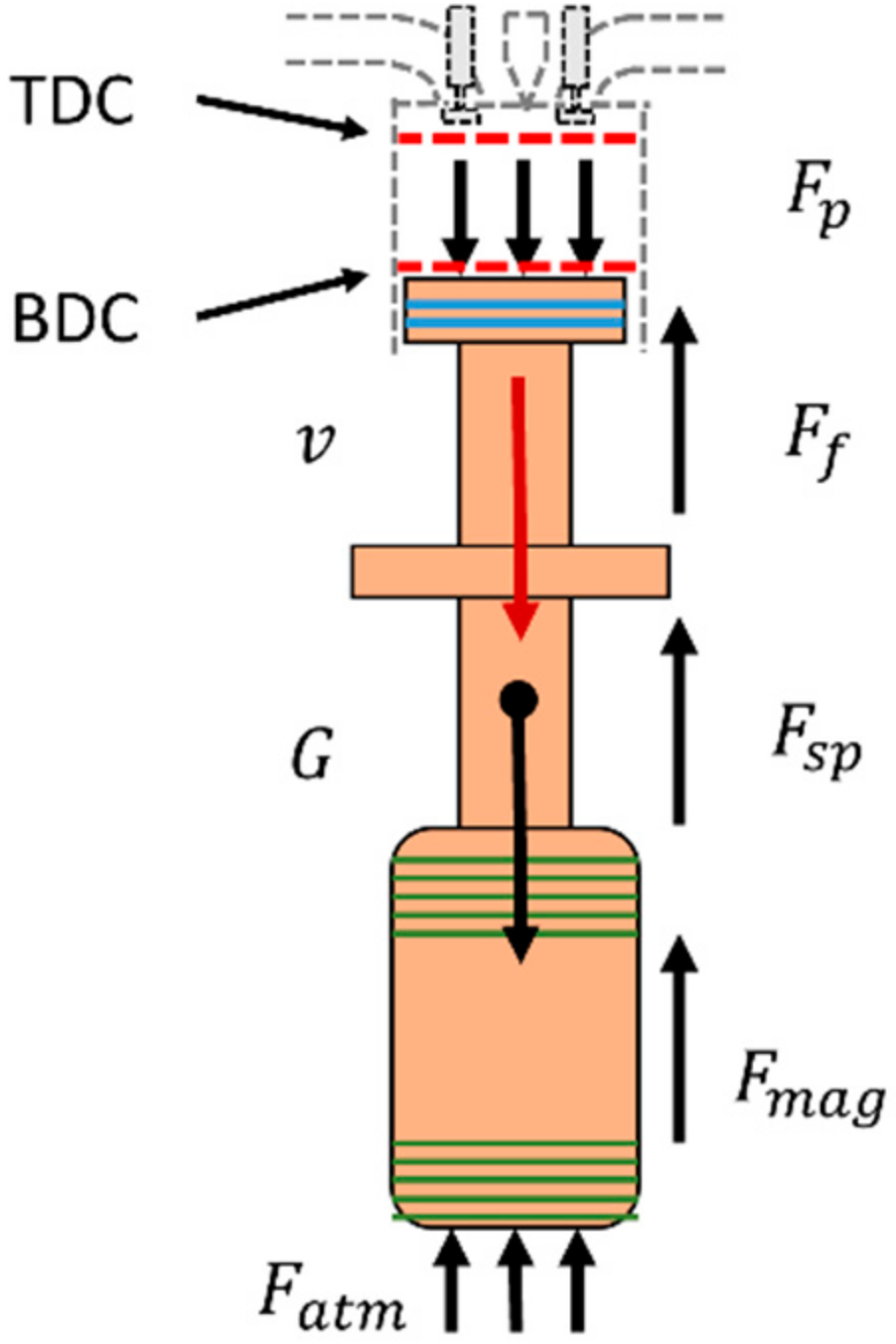
The piston motion trajectory is decided by the resultant force acting on the piston [30,31,32,33]. The force analysis is shown in Figure 3. The dynamic equation is expressed as:
where, Fp is the pressure force of the combustion chamber, Fatm is caused by the atmospheric pressure, G is the gravity acting on the piston assembly, Fsp is the force generated by mechanical spring, Ff is the frictional force between the piston components and the linear guide, and Fmag is the electromagnetic force, M is the mass of the piston assembly, and the displacement between the piston and cylinder head is defined as for the purpose of describing the piston motion. The positive direction is defined to be from TDC to BDC, and the initial position of piston is near the TDC.
3.1. Thermodynamic Modeling of the ICE
In ICE, there are five main stages, intake, compression, combustion, expansion and exhaust. After the scavenging, assuming that the in-cylinder pressure also equals atmospheric pressure. Simultaneously, in combustion chamber, the thermodynamic dynamic is described by a single-zone model, and the assumptions are given below.
- The working medium of the combustion chamber is regard as ideal gas, the pressure change and temperature change follow the ideal gas state equation;
- The combustion process is working in a quantitative working medium, the leakage and gas exchange losses are ignored and the power required by scavenging process is ignored.
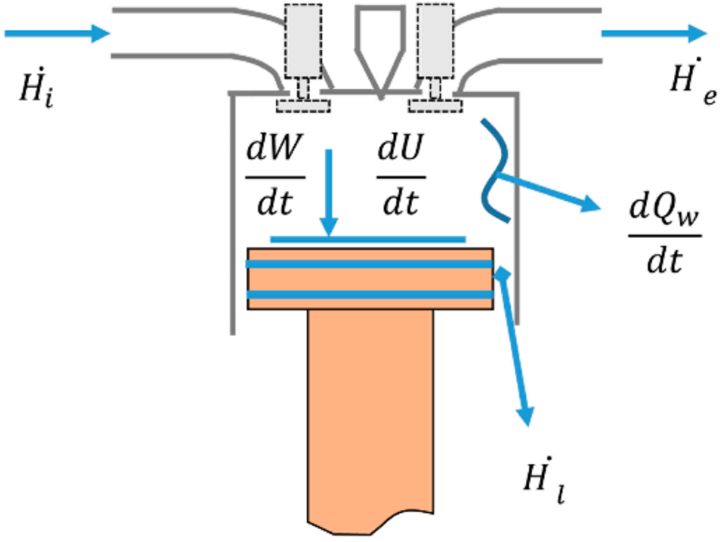
Figure 4 shows the in-cylinder energy flow. In ICE, the chemical energy is converted into heat energy when fuel is burnt. The in-cylinder pressure and temperature increase with the release of heat in the early stage of expansion process. On the basis of the first law of thermodynamics [6,31,34], the thermodynamic process in ICE can be described as:
where, , and are regarded as zero according to the assumptions above.
The change rates of the work done by in-cylinder pressure and the internal energy of the working medium can be expressed as (3) and (4):
By ignoring the gas leakage through the piston ring and the gas exchange loss due to the intake and exhaust process. Equation (2) can be simplified as:
According to the ideal gas state equation, the in-cylinder pressure is satisfied with (6):
The derivative of (6) with respect to time is written as:
Substituting the (8) into (5), the combustion released energy is derived as:
For convenient expression, polytropic exponent is defined as:
In combustion process, the values of polytropic exponent of compression stroke and expansion stroke are different. Here, in order to build model easily, the comprehensive process is simplified, and the specific heat ratio γ is defined as a constant [20].
The in-cylinder pressure can be written as [26]:
In this equation, using the Weiber function [34], the released combustion heat of the combustion process is represented as:
where, the burned mass fraction can be written as:
where, n is combustion quality index, which is a non-dimensional parameters. Its value depends on the compression ratio, the initial combustion temperature and the state of the mixture formation. Normally, for a small gasoline engine, parameter n is in the range from 0 to 3. In our research, the value of n is specified as 2 [4].
There are many generic function models used to represent the heat transfer between the in-cylinder working medium and wall. Here, the Hohenberg model is used to describe this process [29]:
Ultimately, the pressure acting on piston is described as following:
3.2. Mathematical Modeling of Linear Generator
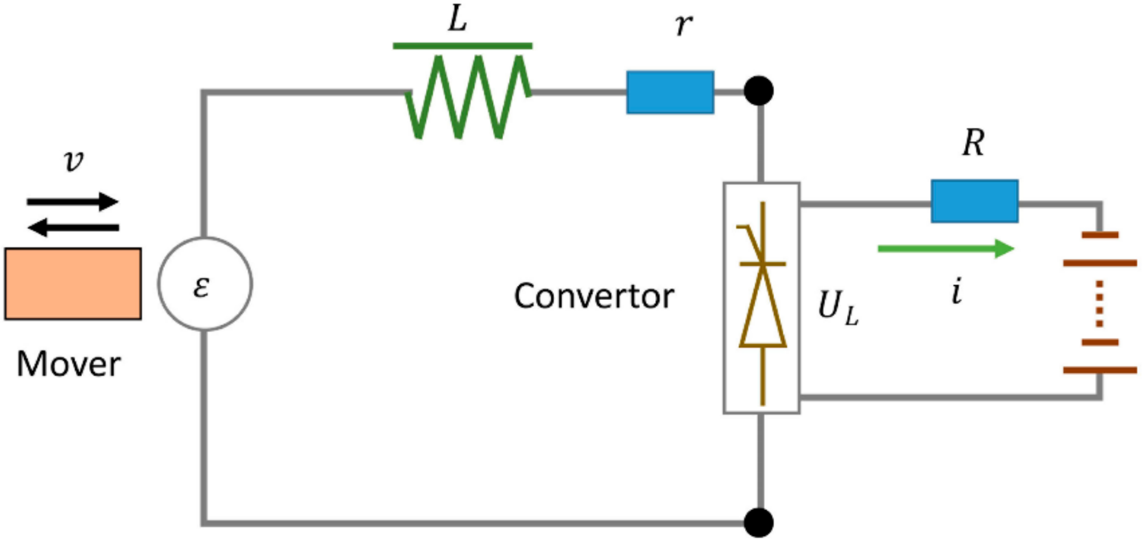
Figure 5 describes the equivalent circuit of motor/generator system, which consists of LEM, convertor and power supply unit. The LEM can be operated as a motor or a generator. The convertor is used to switch the work mode of LEM and control the current. The power supply can work in battery charging mode or discharging mode. The electromagnetic force of LEM is related to the armature current. When the system is in the starting process, LEM works as a motor and the force is described by (16):
When the FPLG is working in generating mode, the back EMF can be written as:
In accordance with Figure 5, the voltage equation for this system is described as:
The electromagnetic force caused by the piston motion also can be presented as (16). The transfer function between ε(t) and i(t) can be written as:
3.3. Modelling of the Rebounding Device
Compared with the in-cylinder pressure and electromagnetic force, the friction force is small, the value of which can be regard as a linear relationship with the piston velocity:
where, f is the frictional coefficient.
In our research, the spring is a constant-stiffness spring, the resilience can be expressed as:
where, xsp0 is the initial length of the mechanical spring.
4. Force Control of the FPLG
In our previous studies [4,18,19], the force control strategy was used to control FPLG with a four-stroke combustion model. Here, the control strategy of two-stroke combustion model is shown in Figure 6.
The piston motion is from static state to stable reciprocating motion by regulating the target currents. Here, the target current in each stroke is a constant value as shown in this schematic diagram. As shown in Figure 6, there are starting process and regulation process before steady operation. In the starting process, the initial position of the piston is close to TDC and the initial states of electromagnetic valves are closed. When FPLG starts working, The LEM works as a driving motor to generate electromagnetic force to push the piston. The driving currents i01, i02 are calculated by Equations (22) and (23). Their directions are same with the velocity of piston:
where, Ecom is the in-cylinder internal energy generated by the compression of the air pressure when the piston is from BDC to TDC, xivo is the switch position of the intake valve, x0 is the initial position of piston, P0 is the intake pressure, and V0 is the initial volume at the end of the scavenging process.
After that, the compression stroke starts. The fuel is injected into the combustion chamber to generate premixed fuel-air mixture. Once the piston runs close to the specified compression ratio, the spark plug will be enabled. The high pressure from the combustion of in-cylinder air-fuel mixture pushes the piston to BDC. Meanwhile, the LEM and the mechanical spring generate a braking force to decelerate the piston until its speed becomes 0. The cycles of starting process will be repeated until the appropriate maximum piston velocity and combustion conditions are achieved.
The valve timing is also depicted in Figure 6. In the first cycle, the exhaust valves are closed and the intake valves are enabled, therefore the combustion chamber is filled with fresh air during the period that the piston move from initial position to BDC. In the rest of the starting process, the exhaust and intake valves will be enabled in turn when the piston reach xsca and xivo, respectively. Then, the exhaust and intake valves will be disabled successively when the piston reach xiv and xsca, respectively. In regulation process and stability process, the electromagnetic valves are operated in the same order. Here, the scavenging position is defined at near 0.085 m.
The main purpose of the regulation process is to realize steady operation. The regulating relationships between target currents ie, ic and the energies are shown in (24):
where, E1 and E2 are the sum of energy losses in expansion and compression stroke, respectively. They are calculated by accumulating iteration. BDC* and TDC* are the target dead center position, BDC and BDC are the actual dead center position. The TDC error is the difference between the target TDC position (TDC*) and the actual TDC position (TDC), and the BDC error is the difference between the target BDC position (BDC*) and the actual BDC position (BDC).
The control diagram is shown in Figure 7. The errors of the dead centers are fed back to the control loop to adjust piston motion. When the TDC error is positive, the in-cylinder pressure is higher than the set pressure and could result in a detonation combustion phenomenon. When the TDC error is negative, the in-cylinder pressure is insufficient to push the piston to BDC*. On the other hand, a large BDC error indirectly affects the TDC position accuracy. These two situations have an impact on the next cycle and steady power output. Therefore, according to the working conditions, the target currents are continuously regulated until the errors are within a suitable range. The calculation corresponds to (22)–(24), the current switching process is determined according to the piston velocity and displacement. At the same time, the mode switching can switch the state of FPLG between motor and generator based on the working conditions.
5. Ladder-like Electromagnetic Force Control Strategy
5.1. Influence Factors of Average Output Power
The average output power is one of the most important performances of FPLG. From the perspective of the work done by electromagnetic force, the average output power can be defined as:
where, WFmag represents the work done by the electromagnetic force. The duration of a cycle is Tcycle, is the average output power, S is the path length of an operation cycle. Ein represents the input energy from fuel combustion in a cycle. Eloss is the loss energy such as friction force, heat transfer, etc. ηi and ηmag are the combustion indicated efficiency and the efficiency of generator, respectively.
In (26), the input energy, path length, loss energy and efficiency in stable operation have tiny variations under specified working conditions. Therefore, Kp is the power factor coefficient can be regarded as a constant. Through (25), the average output power is proportional to the average velocity of the piston when the FPLG is working in a stable process. This means that if the average velocity increases, the average output power can be improved.
5.2. Piston Motion Characteristics Analysis
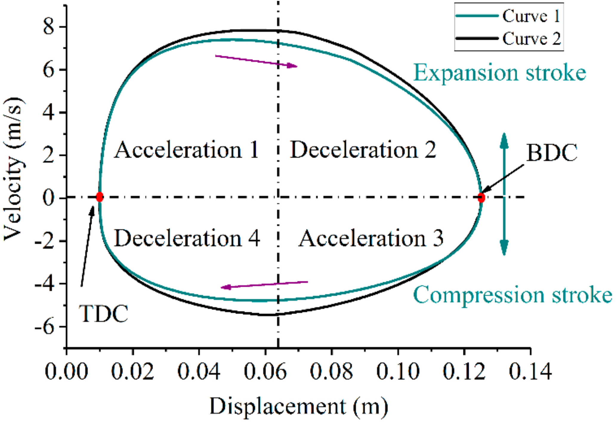
Figure 8 shows the phase trajectories of FPLG. They are obtained when FPLG is in stable operation with two different control strategies. The average velocity of Curve 2 is larger than that of Curve 1. The whole operation process could be divided into four stages, which are Acceleration 1, Deceleration 2, Acceleration 3 and Deceleration 4. The absolute values of the velocity gradually increase in Accelerations 1 and 3, and then drop in Decelerations 2 and 4. If the absolute values of the acceleration increase in these four stages, the average velocity of the piston will be improved, the curve 1 could be changed to curve 2 as shown in Figure 8. Especially, the cover area of the curve, which indicates the output power, will be increased accordingly.
As shown in (1), when the LEM is working in generator mode, the LEM produces an electromagnetic force whose direction is opposite to the piston acceleration. The piston acceleration could be adjusted by changing the value of the electromagnetic force in different zones. Compared to constant force in one stroke as shown in Figure 6, if the electromagnetic force has two different values in the same stroke, i.e., the force decreases in the acceleration zones and increases in the deceleration zones, the piston acceleration would be increased.
In the same way, in each stroke, a minimum reference current in acceleration zone and a maximum reference current at deceleration zone can achieve the maximum acceleration. However, these reference currents have limits to satisfy the requirements of stable operation.
5.3. Ladder-Like Control Strategy
Through the above analysis, the reference current in one stroke is divided into two phases, and the current values in acceleration and deceleration zones are determined by the input energy and the rated current of LEM. Here, the rated current of LEM is used as the reference currents in deceleration zones. No matter that the piston is working in compression or expansion stroke, the appropriate reference current in acceleration zone is the key point that ensuring both the stable operation and high output power. The reference currents i11, i12, i21 and i22 can be obtained according to the following equations:
where, i12, i22 are defined to be equal to ir, which is the rated current of LEM. xsp1 and xsp2 are defined as nominal half-stroke positions.
Figure 9 describes the relationship among the target currents, switching positions and piston displacement. In the operation of FPLG, if a large combustion fluctuation happens, it will cause the errors between the actual and target dead centers. These errors are employed to be a feedback signal to modify reference currents for achieving the stable operation. In this control strategy, when the piston cannot reach the target TDC (BDC), the reference currents of next compression (expansion) stroke will be reduced. On the contrary, the reference currents will be increased when the piston position overshoot the target dead centers.
5.4. Power Amplification Circuit
A single-phase H-bridge circuit is developed to adjust the armature current of the LEM based on the control strategy described above. As shown in Figure 10, the H-bridge driving circuit consists of two by-pass switching tubes (VTa, VTb), three high-frequency capacitances (C1, C2, C3) and a set of super-capacitors (VCH, VCL). There are four insulated gate bipolar translators IGBTs (VT1, VT2, VT3, VT4) in the backbone circuit, which regulate the value and direction of current. The high-frequency capacitance has a function of absorption and protection of switching surge. The switching statuses of IGBTs (VTa, VTb) determine whether the LEM is working on the motoring or generating mode. In order to realize the charging and discharging, the initial state of these two super capacitors VCH and VCL are high and low voltages respectively. In simulation analysis, this H-bridge is verified to be capable of realizing stable operation effectively. Compared with the conventional single-phase H-bridge circuit, it benefits the feedback of electric energy and improves the efficiency of the electrical energy storage.
5.5. The Total Control of FPLG
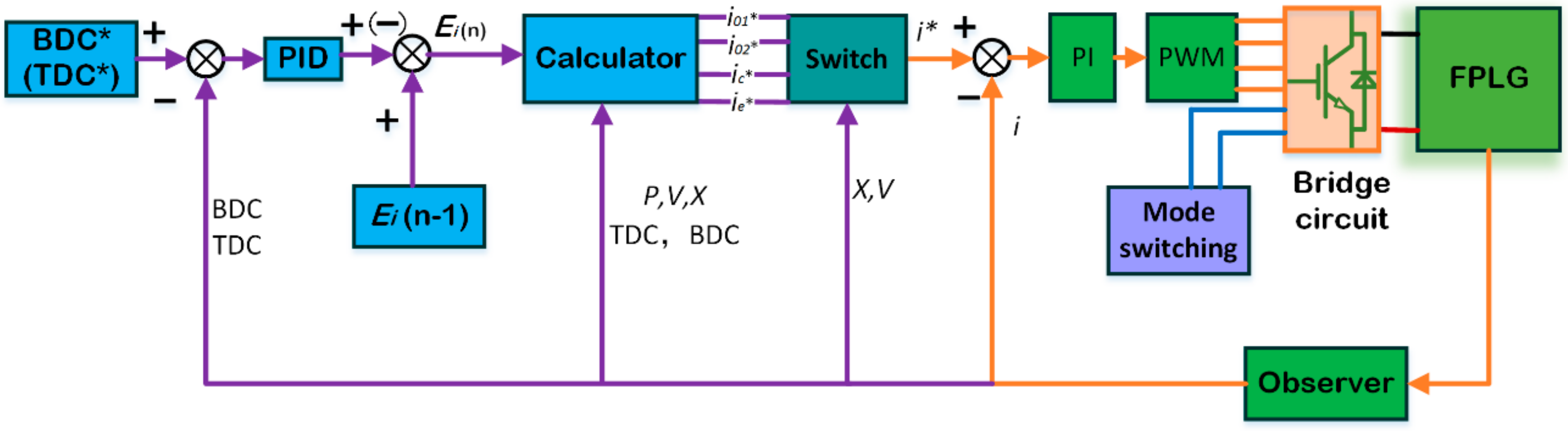
In Figure 11, the input energy is associated with combustion parameters, they are operated according to the introduced working principle. The output energy is adjusted by target current for stable operation in each stroke. The target current is calculated in the energy balance calculation stage. The details of the current control loop of LEM are shown in Figure 12, which is different from Figure 7 on the calculator. In this control strategy, the calculator is designed according to the Equations (22), (27)–(29) with six target current outputs. In this control diagram, the unit of movement state monitoring detects the stages of stroke (compression or expansion stroke) and system stability. Once the stable operation is realized, the parameter optimization is starting. Then, according to the in-cylinder pressure, piston velocity and displacement, the enable positions of electromagnetic valves, injected position and ignition position will be regulated to obtain higher conversion efficiency and lower emissions.
6. Simulation Results
In this section, system dynamic response, average output power, piston displacement and average velocity of piston are analyzed to verify the stability and output performance of the FPLG with the ladder-like control strategy. An H-bridge circuit is implemented in these simulations to control the armature current following the reference current.
6.1. The Stability of Ladder-Like Control Scheme
The dynamic response of the FPLG with the ladder-like control strategy is shown in Figure 13. This figure shows the piston displacement, BDC and TDC errors of the FPLG from the starting process to stable operation. The injected fuel is 30 mg at the beginning, and then it is changed to 35 mg when the FPLG reaches a stable state. From Figure 13, the BDC error has a large fluctuation when the FPLG is starting and the injected fuel mass is suddenly changed, and it settles into a stable band from −0.5 mm to +0.5 mm after several cycles. The position control of TDC has a strong stability performance under this control strategy. The TDC errors are within the stability band even when the injected fuel mass has a 5 mg step changes. The accurate TDC position determines the stability of the whole system. Therefore, the FPLG can be controlled steadily when the fuel mass has a step change within 16% under the ladder-like control scheme.
Figure 14 shows in-cylinder pressure from the starting process and when the injected fuel mass changes. The peak pressure increases to a higher value steadily when the fuel mass changes to 35 mg. The smooth control of peak pressure reflects the feasibility of the ladder-like strategy.
Figure 15 shows the changes of the currents under different fuel mass in stable stage. As shown in Figure 6, i10 and i20 are the starting current, which correspond with the displacement from starting point to BDC1 and the displacement from BDC1 to TDC, respectively.
i11 () and i12 are the regulated currents in expansion stroke, these are correspond with the displacement from TDC to BDC. i21 and i22 are also the regulated currents in the compression stroke; there correspond with the displacement from BDC to TDC. Their reference currents can be calculated by the Equations (22), (27)–(29). When the fuel mass changes from 30 to 35 mg, the value of i11 (−35.7 A) increases to (−53.6 A). However, the others currents have a minor variation. Therefore, the combustion fluctuations are restrained by i11, and can be controlled effectively to accommodate the different fuel masses under the study strategy.
6.2. The Comparative Analysis of Three Control Strategy
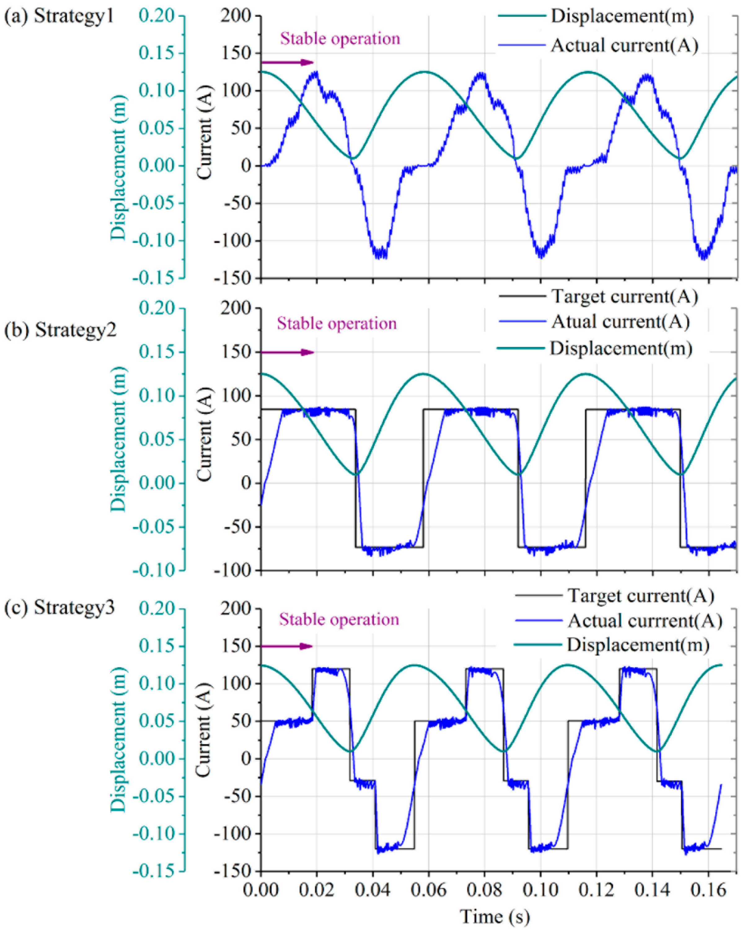
Comparisons of three control strategies when the FPLG is in stable operation are shown in Figure 16. Figure 16a shows the control strategy that the load coefficient and combustion parameters are regarded as the control variables, which is defined as strategy 1. The electromagnetic force of this control strategy is . Figure 16b shows the constant force control strategy during one stroke, which is defined as strategy 2. Figure 16c shows the ladder-like force control strategy under study, which is defined as strategy 3. In order to ensure the input energy is the same, the experiment setup is defined as: fuel mass is 30 mg, xigs = 12 mm, the dead centers are BDC = 125 mm and TDC = 10 mm. Figure 16 also states that the change of the armature current follows the reference current.
From Figure 16, the actual current changes under strategy 1 are proportional to the velocity of piston. Especially, the starting of expansion stroke, the change of the current is faster than other zones. The starting of compression stroke, the changes of currents under three control strategies are similar. The actual currents of strategy 2 and strategy 3 are following the reference currents, this states the power converter unit is effective to control the LEM armature current.
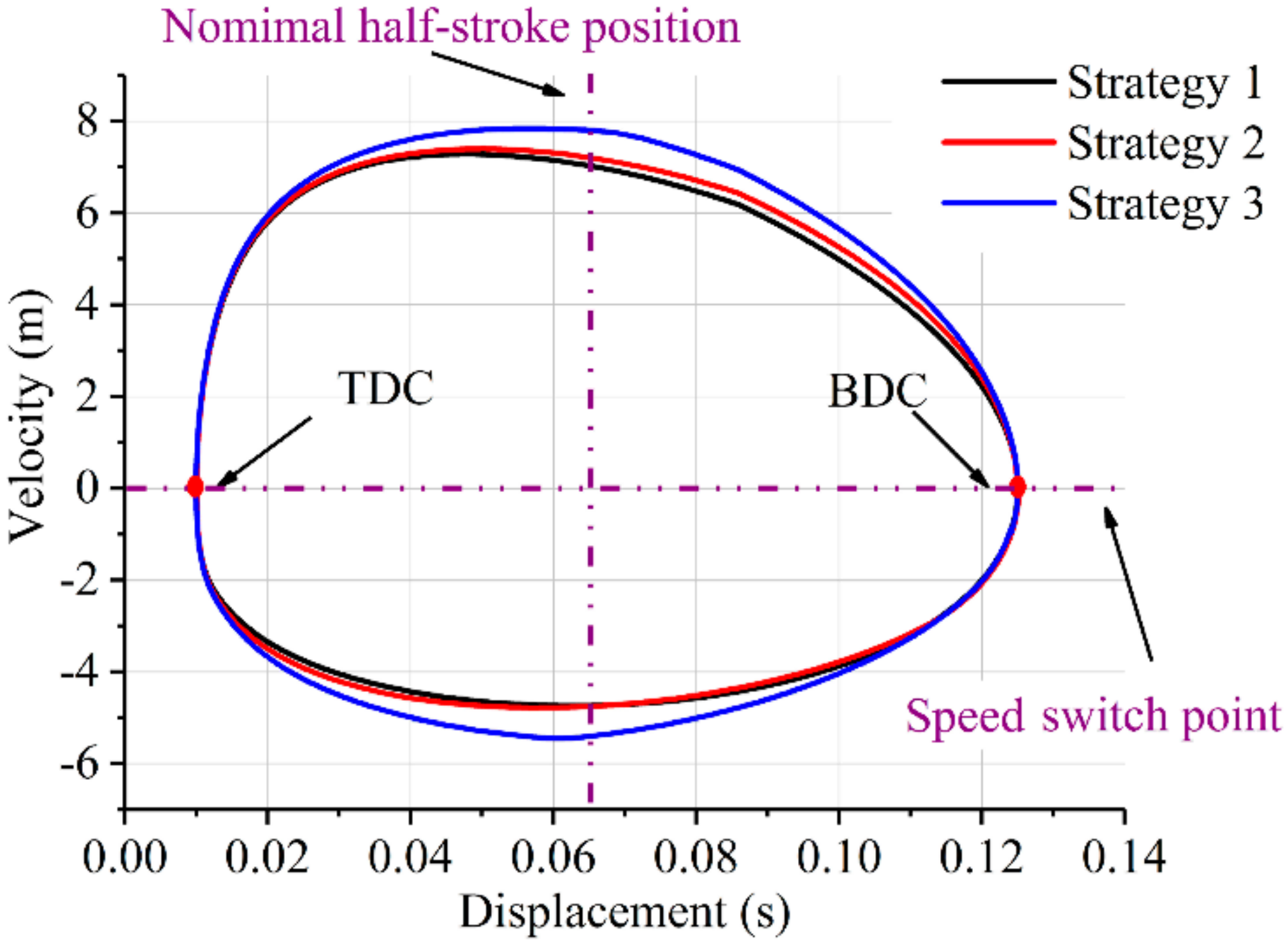
In Figure 17, the displacements of the three control strategies are compared, the initial position and time are unified. This figure shows that the control strategies 1 and 2 almost have no difference on the duration of one cycle, but that of the control strategy 3 is shorter. This illustrates that the piston has a higher average velocity under our ladder-like control strategy. The phase trajectories of three control strategies are compared in Figure 18. The piston velocities of expansion and compression stroke have an increment under strategy 3. In addition, the average velocity of the piston is simulated under different fuel mass. The change range of fuel mass is increasing from 27 to 35 mg by 1 mg each time. In Figure 19, the blue curve is the result of the average velocity using the ladder-like strategy, the average velocity is significantly higher than with the other control strategies. At the same time, the velocity of strategies 1, 2 and 3 is increasing along with the increasing fuel mass, respectively.
In Figure 20, the instantaneous power of three control strategies are compared. The results are obtained when the fuel mass is specified to be 30 mg. In Figure 20a, the average power of strategy 1 is 12.2 kW, which is less than the average power of the strategy 3, 12.9 kW, although their peak values are similar. It is because the average velocity of strategy 3 is higher as shown in Figure 19. In Figure 20b, the strategy 3 has larger amplitude and average power than strategy 2. In Figure 20c, there is no significant difference on average power, though the strategy 1 has larger peak values than strategy 2.
Through analyzing the results above, the strategy 3 has a faster operation frequency when the injected fuel masses are identical. The reduction of electromagnetic force in the acceleration zones and increment of the electromagnetic force in deceleration zones can effectively improve the average velocity of the piston, which contributes to the rapid conversion of energy. Therefore, the average output power of system has a promotion with ladder-like electromagnetic force. Meanwhile, the results are also consistent with the Equation (25).
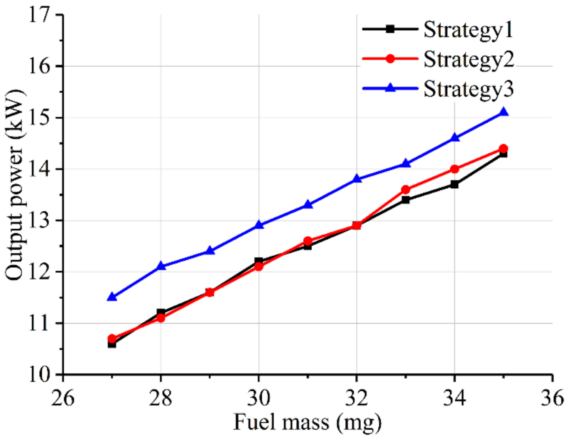
Figure 21 shows that the average power is probably 1 kW higher than two conventional control strategies under the same fuel cycle mass from 27 to 35 mg. From the other view, the proposed ladder-like force control strategy can reduce the operation time by around 7–10% when the work done is the same.
7. Conclusions
In this study, a single-cylinder spring-rebounded FPLG has been developed. A mathematical model including the thermodynamics has been built. A force control strategy of the two-stroke FPLG has been presented and verified to be feasible for steady operation. It was found that the average output power could be improved through increasing the average piston velocity. From further analysis, the changes of reference profile of the electromagnetic force in acceleration and deceleration stages could improve the piston acceleration and hence increase the average velocity. Therefore, a ladder-like force control strategy has been proposed to increase the output power with the same fuel consumption in a cycle. Comparison studies with other two conventional control strategies was conducted. The results show that the output power has a 7–10% increase under same fuel cycle mass with the proposed method. This control strategy has been validated for a single-cylinder FPLG. Its feasibility for other types of FPLGs such as two-cylinder free-piston engine will be further investigated. In addition, compared with the other force control strategy, the disadvantage of the proposed ladder-like force control strategy is that the controller becomes a bit more complicated, but the disadvantage can be ignored compared to the benefits it brings, and experimental tests will be implemented in future work.
Acknowledgments
This work was supported by Joint Funds of National Natural Science Foundation of China and Zhejiang Province (Grant No. U1609206), the International S&T Cooperation Projects of China (Grant No. 2014DFA71010), Ningbo S&T Innovation Team Project (2016B10016), Major Project and Key S&T Program of Ningbo (No. 2016B10019) and Zhejiang Key Laboratory of Robotics and Intelligent Manufacturing Equipment.
Author Contributions
Chi Zhang proposed the design and control strategy of the FPLG and revised the paper; Feixue Chen completed most of the theoretical derivations and simulation analyses and finished this manuscript; Yingzhong Tian and Long Li provided the ideas of the scheme and suggestions about the manuscript; Guilin Yang provided the ideas of the system operation strategies, and also contributed significantly to the enhancement of the manuscript; Zhaoping Xu designed the structure of FPLG and electric engine, Liang Liu contributed the operation principle of FPLG and control strategy of electromagnetic valves, Hongyuan Lian helped to do the analysis work and revise the paper.
Conflicts of Interest
The authors declare no conflict of interest.
Nomenclature
| Total in-cylinder energy of the working medium (W) | |
| Heat released by the burnt fuel (W) | |
| Total amount of heat transfer (W) | |
| External work of working medium (W) | |
| Injected energy (W) | |
| Exhaust energy (W) | |
| Leak energy from the ring piston (W) | |
| Voltage of the storage power unit (V) | |
| The number of winding turns per phase | |
| Temperature of the in-cylinder (°C) | |
| In-cylinder pressure (Pa) | |
| Working volume of ICE chamber (m3) | |
| Total in-cylinder mass of working medium (kg) | |
| Constant volume specific heat (J/(kg·K)) | |
| Gas constant (J/(mol·K)) | |
| Injected fuel mass (kg) | |
| Mass fraction burned | |
| Combustion quality factor | |
| Combustion duration (s) | |
| Time variable (s) | |
| Heat transfer surfaces (m2) | |
| Mean piston velocity (m/s) | |
| Average surface temperature of the cylinder wall (°C) | |
| Atmospheric pressure (Pa) | |
| Scavenging position (m) | |
| Intake valves open position (m) | |
| Ignition position (m) |
References
- Mikalsen, R.; Roskilly, A.P. A review of free-piston engine history and applications. Appl. Therm. Eng. 2007, 27, 2339–2352. [Google Scholar] [CrossRef]
- Hung, N.B.; Lim, O. A review of free-piston linear engines. Appl. Energy 2016, 178, 78–97. [Google Scholar] [CrossRef]
- Sun, P.; Zhang, C.; Chen, J.; Zhao, F.; Liao, Y.; Yang, G.; Chen, C.; Sciubba, E. Decoupling design and verification of a free-piston linear generator. Energies 2016, 9, 1067. [Google Scholar] [CrossRef]
- Xu, Z.; Chang, S. Prototype testing and analysis of a novel internal combustion linear generator integrated power system. Appl. Energy 2010, 87, 1342–1348. [Google Scholar] [CrossRef]
- Feng, H.; Song, Y.; Zuo, Z.; Shang, J.; Wang, Y.; Roskilly, A. Stable operation and electricity generating characteristics of a single-cylinder free piston engine linear generator: Simulation and experiments. Energies 2015, 8, 765–785. [Google Scholar] [CrossRef]
- Mikalsen, R.; Roskilly, A.P. Coupled dynamic—Multidimensional modelling of free-piston engine combustion. Appl. Energy 2009, 86, 89–95. [Google Scholar] [CrossRef]
- Mikalsen, R.; Roskilly, A.P. The control of a free-piston engine generator. Part 2: Engine dynamics and piston motion control. Appl. Energy 2010, 87, 1281–1287. [Google Scholar] [CrossRef]
- Jia, B.; Mikalsen, R.; Smallbone, A.; Zuo, Z.; Feng, H.; Roskilly, A.P. Piston motion control of a free-piston engine generator: A new approach using cascade control. Appl. Energy 2016, 179, 1166–1175. [Google Scholar] [CrossRef]
- Jia, B.; Zuo, Z.; Tian, G.; Feng, H.; Roskilly, A.P. Development and validation of a free-piston engine generator numerical model. Energy Convers. Manag. 2015, 91, 333–341. [Google Scholar] [CrossRef]
- Hannson, J.; Leksell, M.; Carlsson, F. Minimizing power pulsations in a free piston energy converter. In Proceedings of the European Conference on Power Electronics and Applications, Dresden, Germany, 11–14 September 2005; p. 8. [Google Scholar]
- Lin, J.; Chang, S. Modeling and simulation of a novel internal combustion-linear generator integrated power system using matlab/simulink. In Proceedings of the IEEE International Conference on Power and Energy, Kota Kinabalu, Malaysia, 2–5 December 2012; pp. 435–439. [Google Scholar]
- Kosaka, H.; Akita, T.; Moriya, K.; Goto, S.; Hotta, Y.; Umeno, T.; Nakakita, K. Development of free piston engine linear generator system Part 1—Investigation of fundamental characteristics. SAE Tech. Pap. 2014, 1, 882–888. [Google Scholar]
- Němeček, P.; Vysoký, O. Control of two-stroke free-piston generator. In Proceedings of the 6th Asian Control Conference, Bali, Indonesia, 18–21 July 2006. [Google Scholar]
- Zhang, C.; Li, K.; Sun, Z. Modeling of piston trajectory-based HCCI combustion enabled by a free piston engine. Appl. Energy 2015, 139, 313–326. [Google Scholar] [CrossRef]
- Li, K.; Zhang, C.; Sun, Z. Precise piston trajectory control for a free piston engine. Control Eng. Pract. 2015, 34, 30–38. [Google Scholar] [CrossRef]
- Goto, S.; Moriya, K.; Kosaka, H.; Akita, T.; Hotta, Y.; Umeno, T.; Nakakita, K. Development of free piston engine linear generator system Part 2—Investigation of control system for generator. SAE Tech. Pap. 2014, 1, 247–254. [Google Scholar]
- Zhang, C.; Sun, Z. Using variable piston trajectory to reduce engine-out emissions. Appl. Energy 2016, 170, 403–414. [Google Scholar] [CrossRef]
- Xu, Z.; Chang, S. Hierarchical hybrid control of a four-stroke free-piston engine for electrical power generation. In Proceedings of the International Conference on Mechatronics and Automation, Changchun, China, 9–12 August 2009; pp. 4045–4049. [Google Scholar]
- Xu, Z.; Chang, S. Improved moving coil electric machine for internal combustion linear generator. IEEE Trans. Energy Convers. 2010, 25, 281–286. [Google Scholar]
- Sun, P.; Zhang, C.; Chen, J.; Zhao, F.; Liao, Y.; Yang, G.; Chen, C. Hybrid system modeling and full cycle operation analysis of a two-stroke free-piston linear generator. Energies 2017, 10, 213. [Google Scholar] [CrossRef]
- Feng, H.; Guo, Y.; Song, Y.; Guo, C.; Zuo, Z. Study of the injection control strategies of a compression ignition free piston engine linear generator in a one-stroke starting process. Energies 2016, 9, 453. [Google Scholar] [CrossRef]
- Gong, X.; Zaseck, K.; Kolmanovsky, I.; Chen, H. Dual-loop control of free piston engine generator. IFAC-PapersOnLine 2015, 48, 174–180. [Google Scholar] [CrossRef]
- Gong, X.; Zaseck, K.; Kolmanovsky, I.; Chen, H. Modeling and predictive control of free piston engine generator. In Proceedings of the 2015 American Control Conference, Chicago, IL, USA, 1–3 July 2015; pp. 4735–4740. [Google Scholar]
- Yang, R.; Gong, X.; Hu, Y.; Chen, H. Motion control of free piston engine generator based on LQR. In Proceedings of the 34th Chinese Control Conference, Hangzhou, China, 28–30 July 2015; pp. 8091–8096. [Google Scholar]
- Xia, H.; Pang, Y.; Grimble, M. Hybrid modelling and control of a free-piston energy converter. In Proceedings of the 2016 IEEE International Conference on Control Applications, Munich, Germany, 4–6 October 2006; pp. 373–378. [Google Scholar]
- Sun, P.; Zhao, F.; Zhang, C.; Zhang, J. Dynamic simulation of a novel free-piston linear generator. In Proceedings of the 2015 IEEE International Conference on Advanced Intelligent Mechatronics, Busan, South Korea, 7–11 July 2015; pp. 1641–1646. [Google Scholar]
- Virsik, R.; Heron, A. Free piston linear generator in comparison to other range-extender technologies. In Proceedings of the Electric Vehicle Symposium and Exhibition, Barcelona, Spain, 17–20 November 2014; pp. 1–7. [Google Scholar]
- Kim, J.; Bae, C.; Kim, G. Simulation on the effect of the combustion parameters on the piston dynamics and engine performance using the Wiebe function in a free piston engine. Appl. Energy 2013, 107, 446–455. [Google Scholar] [CrossRef]
- Hung, N.B.; Lim, O.T. A study of a two-stroke free piston linear engine using numerical analysis. J. Mech. Sci. Technol. 2014, 28, 1545–1557. [Google Scholar] [CrossRef]
- Cawthorne, W.R.; Famouri, P.; Chen, J.; Clark, N.N.; McDaniel, T.I.; Atkinson, R.J.; Nandkumar, S.; Atkinson, C.M.; Petreanu, S. Development of a linear alternator-engine for hybrid electric vehicle applications. IEEE Trans. Veh. Technol. 1999, 48, 1797–1802. [Google Scholar] [CrossRef]
- Li, Q.-F.; Xiao, J.; Huang, Z. Parametric study of a free piston linear alternator. Int. J. Automot. Technol. 2010, 11, 111–117. [Google Scholar] [CrossRef]
- Miao, Y.; Zuo, Z.; Feng, H.; Guo, C.; Song, Y.; Jia, B.; Guo, Y. Research on the combustion characteristics of a free-piston gasoline engine linear generator during the stable generating process. Energies 2016, 9, 655. [Google Scholar] [CrossRef]
- Mikalsen, R.; Roskilly, A.P. Performance simulation of a spark ignited free-piston engine generator. Appl. Therm. Eng. 2008, 28, 1726–1733. [Google Scholar] [CrossRef]
- Shoukry, E.; Taylor, S.; Clark, N.; Famouri, P. Numerical simulation for parametric study of a two-stroke direct injection linear engine. SAE Tech. Pap. 2002. [Google Scholar] [CrossRef]
Figure 1.
Basic configurations of FPLG, (a) The structure diagram; (b) The prototype of FPLG.

Figure 2.
The 3D structure of voice coil motor.

Figure 3.
The force analysis of the piston assembly.

Figure 4.
The thermodynamic process of the combustion chamber.

Figure 5.
The equivalent circuit of motor/generator system.

Figure 6.
Schematic diagram of the operating principle.
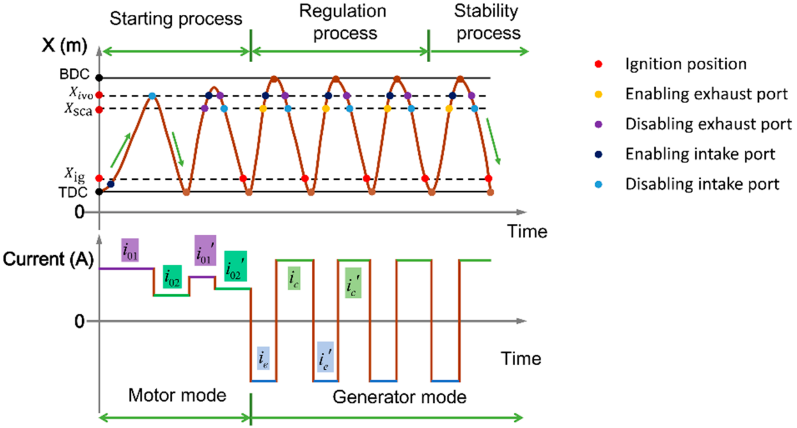
Figure 7.
The force control strategy of two-stroke.

Figure 8.
The phase trajectory of FPLG.

Figure 9.
The schematic diagram of the Ladder-like control strategy.
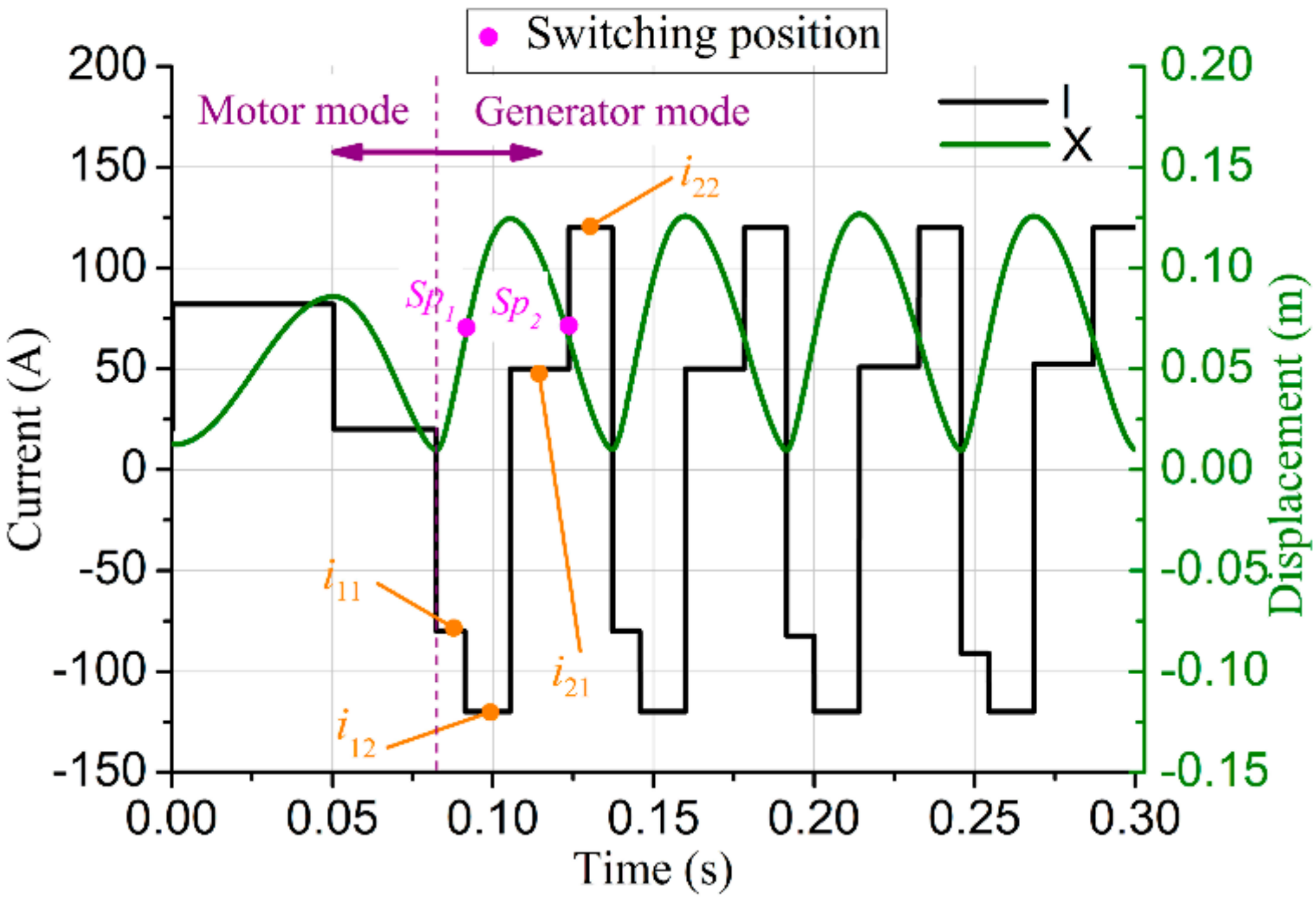
Figure 10.
The H-Bridge circuit of LEM.

Figure 11.
The control strategy diagram.
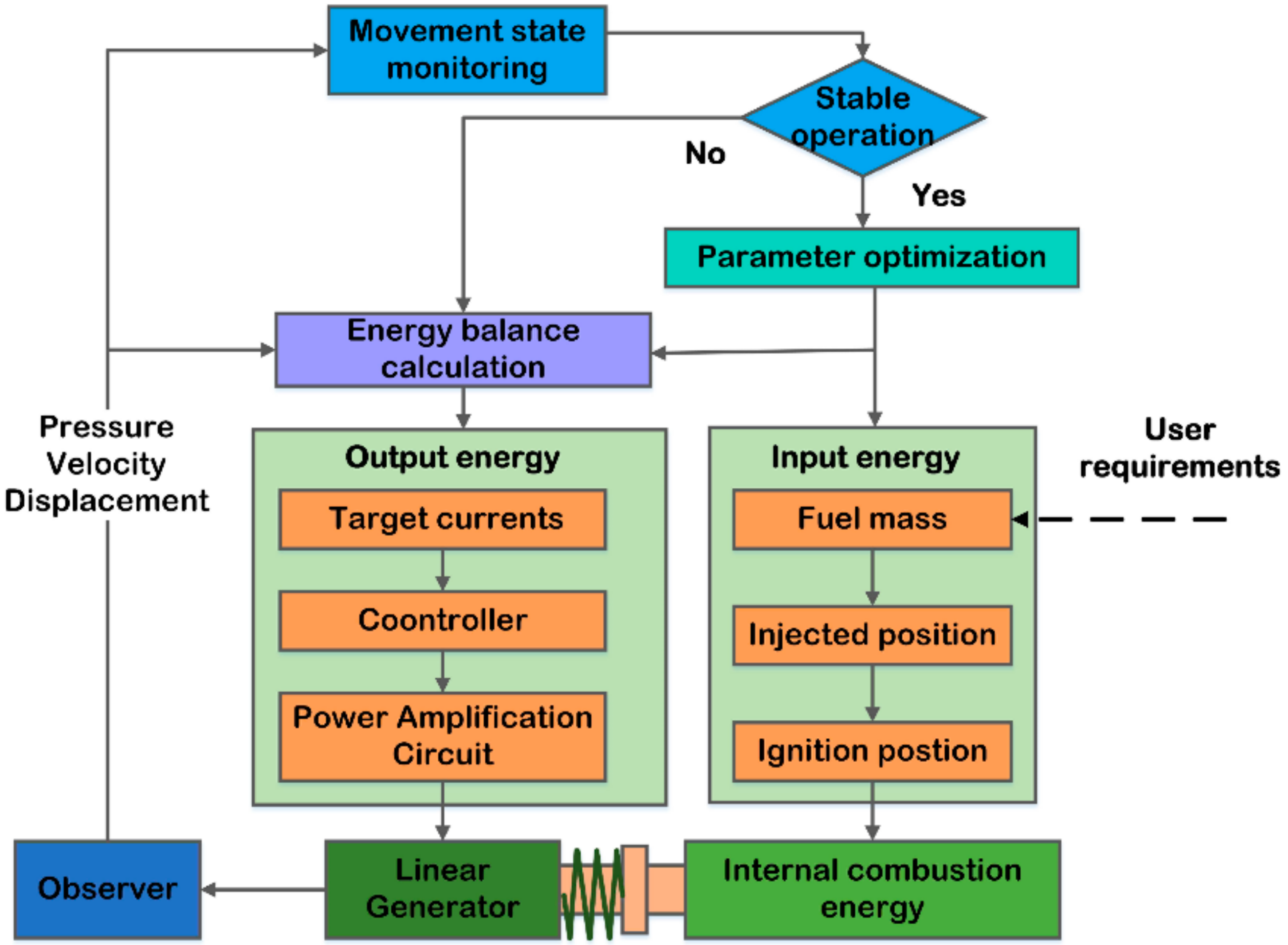
Figure 12.
The control strategy of ladder-like.
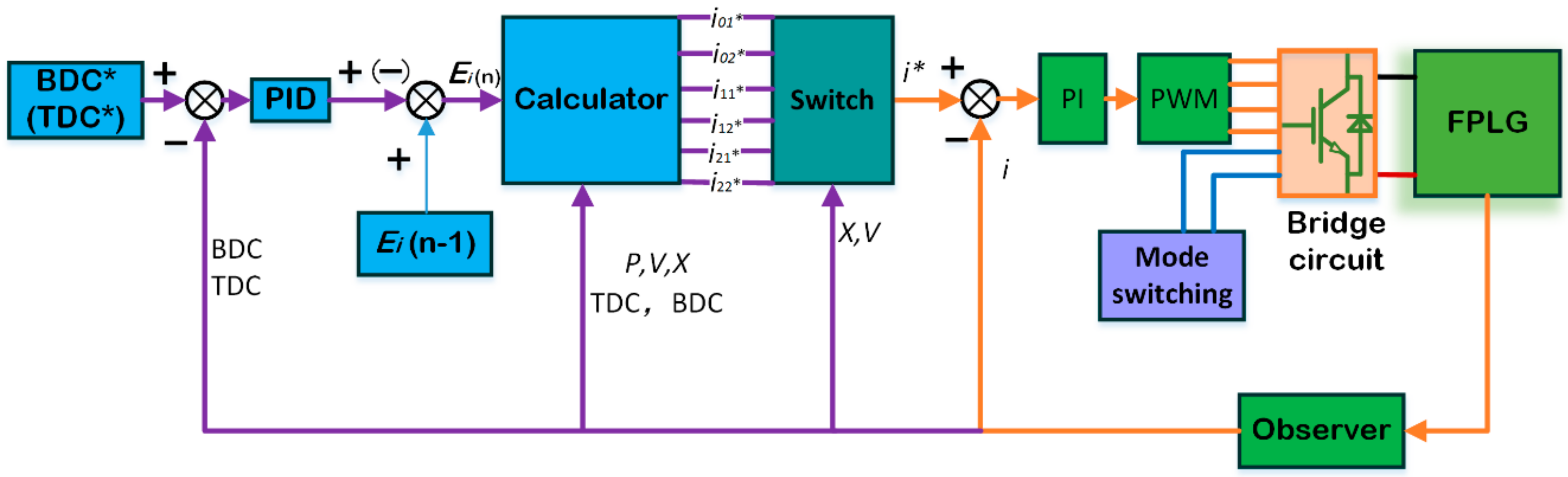
Figure 13.
Dead center errors of piston.
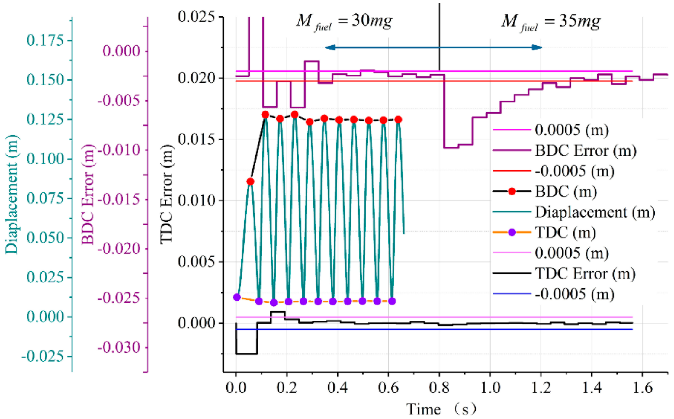
Figure 14.
In-cylinder pressure of combustion chamber.
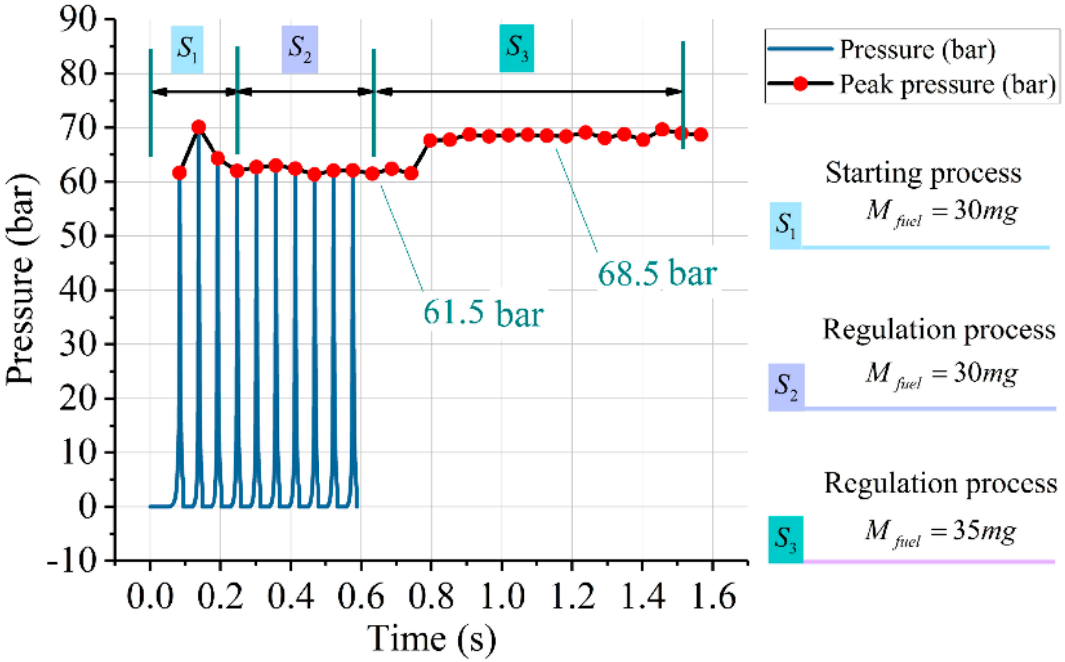
Figure 15.
Phase trajectory and currents of the ladder-like control strategy.
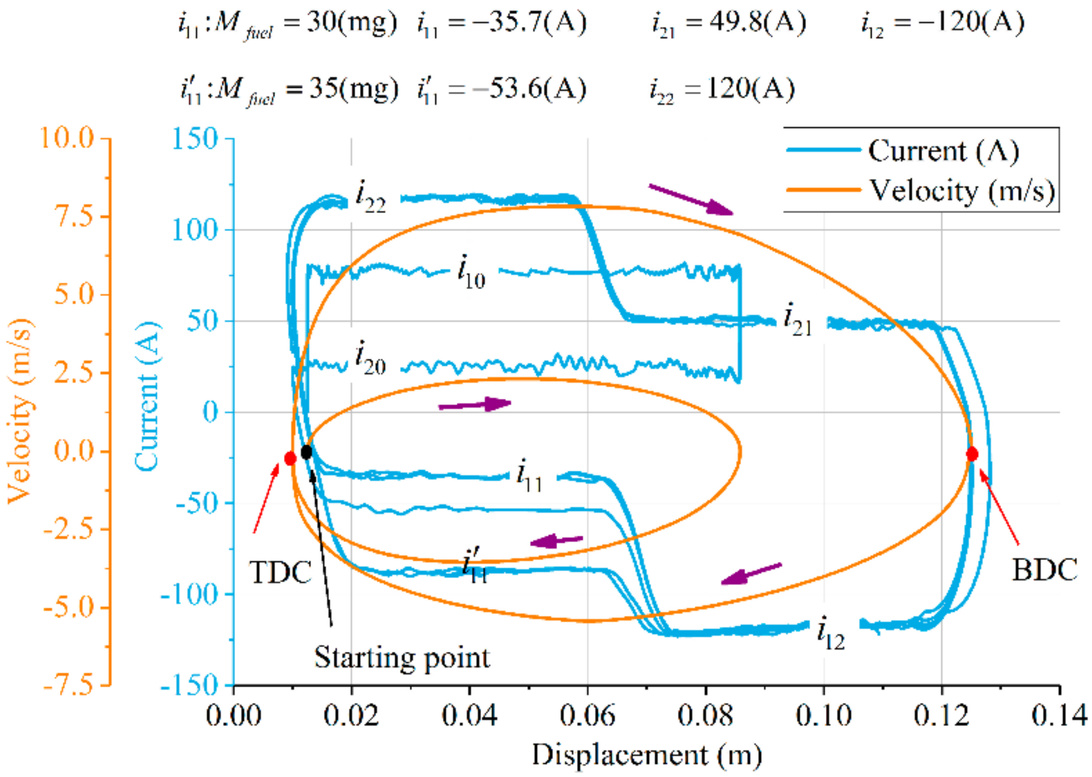
Figure 16.
Three control strategies during the stable operation period.

Figure 17.
Piston displeacement diagram.
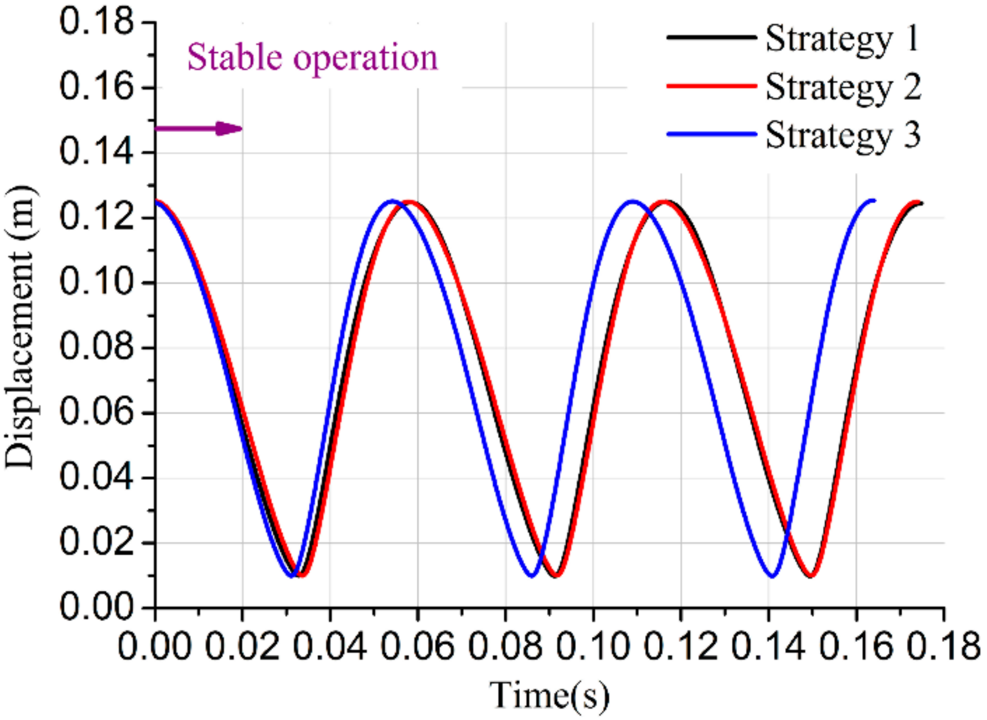
Figure 18.
Phase trajectory of control strategies.

Figure 19.
Piston average velocity with three control strategies.
Figure 20.
Instantaneous power diagram.
Figure 21.
Average output power diagram.


Table 1.
The key geometric and performance parameters of FPLG.
| Parameters | Value |
|---|---|
| Nominal output power Pnom (kW) | 15 |
| Operating frequency fz (Hz) | 15–25 |
| Efficiency of generator ηmag (%) | 94 |
| Combustion indication efficiency ηi (%) | 48 |
| Frictional coefficient f (N·(m/s)−1) | 12 |
| Piston sectional area Ap (m2) | 0.0082 |
| Load resistance R (Ω) | 6 |
| Internal resistance r (Ω) | 0.33 |
| Excess air coefficient α | 1.05 |
| Specific heat ratio γ | 1.32 |
| Combustion duration Tc (m·s) | 4 |
| Combustion quality index n | 2 |
| Thrust constant Ki (N/A) | 34.7 |
| Fuel lower heating value Hu (J/mg) | 44 |
| Elasticity coefficient Ksp (kN/m) | 80 |
| Target top dead center TDC* (mm) | 10 |
| Target bottom dead center BDC* (mm) | 125 |
| Equivalence ratio εe | 1 |
© 2018 by the authors. Licensee MDPI, Basel, Switzerland. This article is an open access article distributed under the terms and conditions of the Creative Commons Attribution (CC BY) license (http://creativecommons.org/licenses/by/4.0/).
Share and Cite
MDPI and ACS Style
Zhang, C.; Chen, F.; Li, L.; Xu, Z.; Liu, L.; Yang, G.; Lian, H.; Tian, Y. A Free-Piston Linear Generator Control Strategy for Improving Output Power. Energies 2018, 11, 135. https://doi.org/10.3390/en11010135
AMA Style
Zhang C, Chen F, Li L, Xu Z, Liu L, Yang G, Lian H, Tian Y. A Free-Piston Linear Generator Control Strategy for Improving Output Power. Energies. 2018; 11(1):135. https://doi.org/10.3390/en11010135
Chicago/Turabian StyleZhang, Chi, Feixue Chen, Long Li, Zhaoping Xu, Liang Liu, Guilin Yang, Hongyuan Lian, and Yingzhong Tian. 2018. "A Free-Piston Linear Generator Control Strategy for Improving Output Power" Energies 11, no. 1: 135. https://doi.org/10.3390/en11010135
Note that from the first issue of 2016, this journal uses article numbers instead of page numbers. See further details here.