Complimentary Force Allocation Control for a Dual-Mover Linear Switched Reluctance Machine
by
 ,
,
J. F. Pan
1, 
Weiyu Wang
1,
Bo Zhang
1 ,
,
Eric Cheng
2,
Jianping Yuan
3,
Li Qiu
1,* and
Xiaoyu Wu
1,* 1
College of Mechatronics and Control Engineering, Shenzhen University, Shenzhen 518060, China
2
Department of Electrical Engineering, Hong Kong Polytechnic University, Hong Kong, China
3
Laboratory of Advanced Unmanned Systems Technology, Research Institute of Northwestern Polytechnical University in Shenzhen, Shenzhen 518060, China
*
Authors to whom correspondence should be addressed.
Energies 2018, 11(1), 23; https://doi.org/10.3390/en11010023
Submission received: 27 October 2017
/
Revised: 24 November 2017
/
Accepted: 14 December 2017
/
Published: 22 December 2017
(This article belongs to the Special Issue Networked and Distributed Control Systems)
Abstract
:This paper inspects the complementary force allocation control schemes for an integrated, dual-mover linear switched reluctance machine (LSRM). The performance of the total force is realized by the coordination of the two movers. First, the structure and characteristics of the LSRM are investigated. Then, a complimentary force allocation control scheme for the two movers is proposed. Next, three force allocation methods—constant proportion, constant proportion with a saturation interval and error compensation, and the variable proportion allocation strategies—are proposed and analyzed, respectively. Experimental results demonstrate that the complimentary force interaction between the two movers can effectively reduce the total amount of force ripples from each method. The results under the variable proportion method also show that dynamic error values falling into 0.044 mm and −0.04 mm under the unit ramp force reference can be achieved. With the sinusoidal force reference with an amplitude of 60 N and a frequency of 0.5 Hz, a dynamic force control precision of 0.062 N and 0.091 N can also be obtained.
1. Introduction
Precise force control exists in many industrial situations, such as tensile and compression tests in measurement systems, the pick and grasp actions of manipulators from robotic arms, and product/component transportation in product lines [1]. Instead of using hydraulic or pneumatic systems, the force outputs from electric machines are more stable and precise and they are more suitable for high-precision, low force output applications [2]. Precise force control applications often require that the force output should follow a designated force command of a constant or a varied waveform with a certain precision. Meanwhile, the force ripples should be kept at a certain level [3]. Since linear machines (LMs) have the advantages of direct force output with the annihilation of any rotary-to-linear translators [4], force can be controlled with more precision compared to the solution of rotary motors coupled with rotary-to-linear transmissions [5].
However, force control in LMs still has some limitations. Since the power of any single motor-based control system is limited, the force control performance deteriorates severely if the load is beyond the capacity of the motor [6]. In spite of large load situations, the machine is often required to work for a certain period of time for overload operations with disturbances. The force characteristics of LMs are often nonlinear, and some compensation or linearization schemes should be introduced to reduce the force ripples to obtain a smooth force output profile [7]. Therefore, the capacity and accuracy of the force control from a single LM alone sometimes cannot be guaranteed.
Current research work focuses on the force improvement of single LMs, and the topics are mainly concentrated on machine design and optimization. Articles [8,9] discuss the design optimization of a linear induction motor by a proper arrangement of the windings. The permanent magnets in the linear synchronous permanent magnetic machines (LSPMMs) bring an inevitable detent force. Articles [10,11] talk about thrust force output improvement and force ripple reductions for LSPMMs. In [10], the optimum design of a transverse LSPMM to reduce the detent force is presented by using a response surface methodology and genetic algorithms based on a finite element analysis and an experiment. Article [11] talks about the optimization of a transverse flux LSPMM based on particle swarm optimization. The objective of the optimization was to reduce the motor’s weight while maximizing the thrust force as well as minimizing the detent force of the motor, and it was verified by a finite element analysis and experimental results. For elevator applications, an optimal structure design and magnetic force analysis that employs LSPMMs are presented in [7]. A multi-air gap LSPMM for aeronautical applications is designed and optimized for improved force output performance in [10]. Force ripple reduction can also be realized by characteristic linearization [12,13,14] and advanced force control methods [15,16,17,18]. However, the linearization schemes or control strategies for a single mover-based LM cannot provide a sufficient amount of force and the force ripples are hard to maintain at a precise level, especially during a change of movement direction. Therefore, it is difficult to guarantee the accuracy of the total force output.
The force output level or accuracy can be further guaranteed by a multi-mover LM structure if the movers can work coordinately. Based on this idea, in this paper, a novel integrated, dual-mover linear switched reluctance motor (LSRM) based on a stator is proposed. Compared to its single mover-based LSRM counterpart, this machine can effectively enhance the force output level and increase the precision of the force output at the same time.
Through a detailed theoretical analysis, different force allocation methods are investigated, such as the constant proportion method, the constant proportion with saturation interval and error compensation method, and the variable proportion allocation method. Experimental results also demonstrate that the complimentary force interaction between the two movers can effectively reduce the total amount of force ripples. The results also show that under the variable proportion method, the dynamic force error values can be controlled within 0.044 mm and −0.04 mm under the unit ramp force reference. A force error falling into 0.062 N and 0.091 N can be achieved under the variable proportion allocation strategy for a sinusoidal force reference with an amplitude to 60 N and a frequency of 0.5 Hz.
Currently, there are few studies investigating precise force control by the cooperation of multiple objects, especially LMs. The contribution of this paper can be summarized as follows. First, an attempt at precise force control by the cooperative force of an integrated linear machine from dependent movers is investigated. Second, the analysis of different simple yet effective force allocation schemes is studied and the characteristics of the scheme are inspected in detail. Experimental tests show that a relative force precision falling into 0.016% can be achieved under the cooperation of two movers.
The structure of this paper is as follows. First, the structure of an integrated, dual-mover LSRM based on a double-sided and asymmetric machine topology is discussed in Section 2. Section 3 presents the force control scheme of the proposed machine. Section 4 investigates the detailed force allocation methodologies, and is supported by a theoretical analysis. Section 5 describes the experimental validation for different force allocation schemes. Conclusion remarks are presented in Section 6.
2. Structure and Principle of the LSRM
The principle of the dual-mover LSRM conforms to that of switched reluctance machines. The magnetic lines of the mover blocks follow the closed loops according to the stator. The magnetic lines circulate the path with minimum reluctance. As shown in Figure 1a, the machine topology of either mover, it contains three pairs of mover blocks, and the three phases are marked as AA’, BB’, and CC’, respectively. As shown in Figure 1b, the picture of the machine prototype, two identical movers are installed in the stator, and they can translate according to the stator base. The proposed linear machine applies an asymmetric structure [19]. The serially connected phases, such as phase AA’, are not exactly mirrored along the axis of the moving platform. The stator teeth are not exactly symmetric to the axis of the moving platform as well. Six mover blocks are mounted on an aluminum fixture to form the mover, and are supported by a pair of linear guides. Both mover1 and mover2 are connected with two identical springs, and the left point of the spring for mover1 is connected to the base and the total force output can be measured at this point. Each mover is mounted with a linear encoder to obtain real-time position information. Mutual inductance can be neglected between any two phases from any one mover. Table 1 lists the main specifications of this machine, which include the electrical and mechanical parameters.
The voltage balancing equation for any one phase from any mover is depicted as follows [20]
where = 1, 2, stands for the two movers, = AA’, BB’, CC’ represents the three-phase windings for each mover, and , , and are the supply phase voltage, the phase resistance, and the phase flux linkage, respectively. Furthermore, we have
where and are the phase current and displacement of the mover, respectively. Since the two movers can be regarded as identical, from the mechanical side, the generated electromagnetic force and for each mover can be formulated as
where and are mass of the mover and friction coefficient, respectively, and and are the tension force from spring1 and spring2, respectively. The propulsion force from either mover can be represented as [20]
where is the co-energy. Neglecting the saturation effect, the propulsion force output for each mover can be characterized as [21]
where is the phase inductance.
3. Force Control Scheme
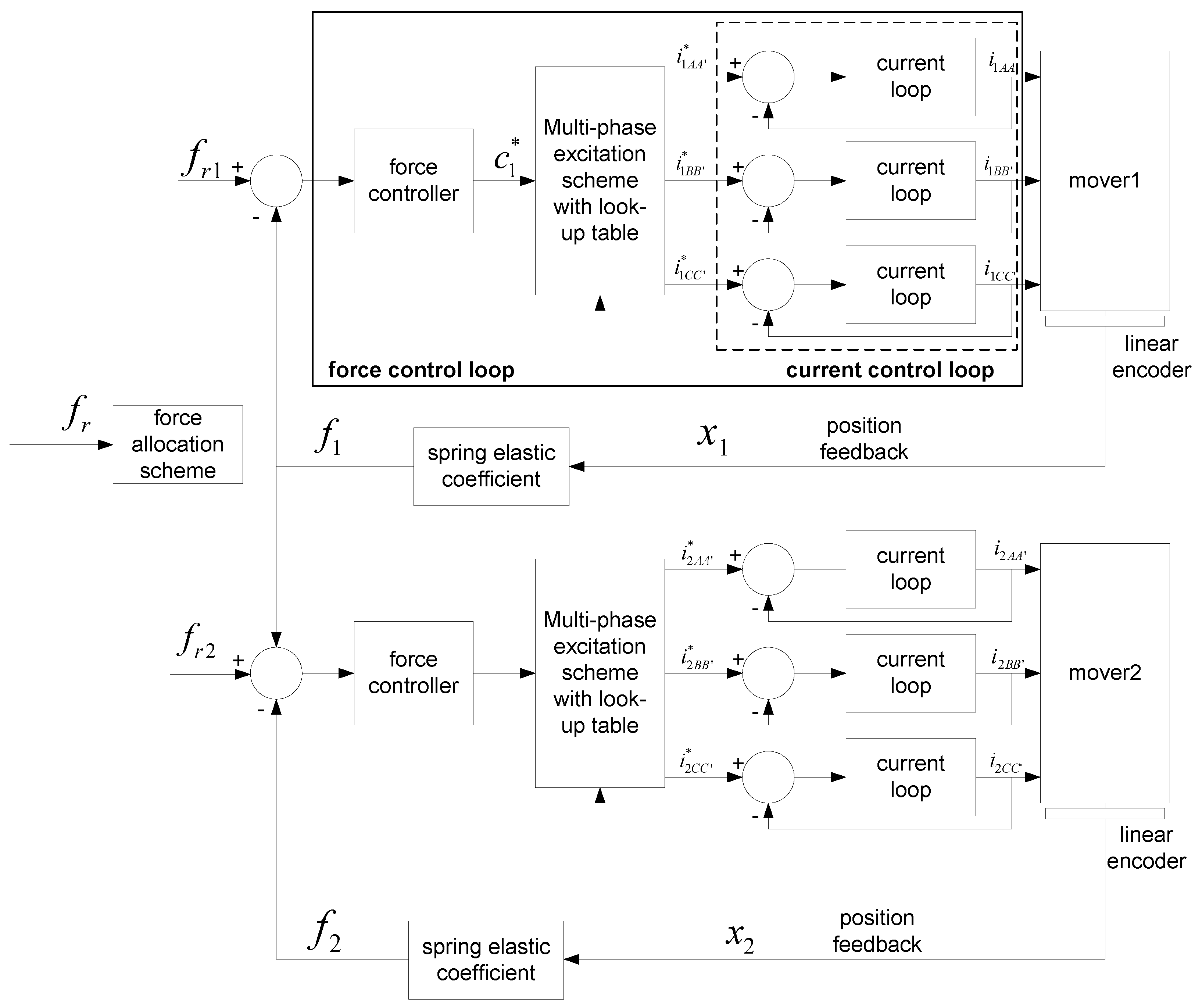
The control diagram of the complimentary force scheme is depicted in Figure 2. It mainly consists of two control parts: the force controller for each mover and the force allocation scheme. The ultimate goal of complimentary control is to realize a total force output that follows the force reference in a designated manner with a certain precision and dynamics. The force control module is to derive a precise force control performance for each mover, and the force allocation scheme module is responsible for the deployment of force command ( and ) for each mover according to the total force reference . Since a dynamic force measurement is difficult to obtain, the displacement for each mover can be detected by a linear encoder and the force of each spring can thus be indirectly calculated as the multiplication of the elastic coefficient of the spring and the displacement from the linear encoder.
Each mover applies the same single force control strategy. As shown in Figure 2, the force controller from each mover calculates the error from the force reference and actual force feedback. From the above equations, the motion from each mover behaves according to a highly nonlinear relationship between force and current [22]. For the smooth operation of LSRMs, the propulsion force from the movers should remain at reasonable values with minimum fluctuations [23]. One of the effective methods for force ripple minimization is the introduction of a multi-phase excitation scheme based on force distribution functions. The multi-phase excitation scheme is adopted and tabulated in Table 2. Since the distance period of each mover is 12 mm, current position is divided into six regions for the proper excitation of the phase(s).
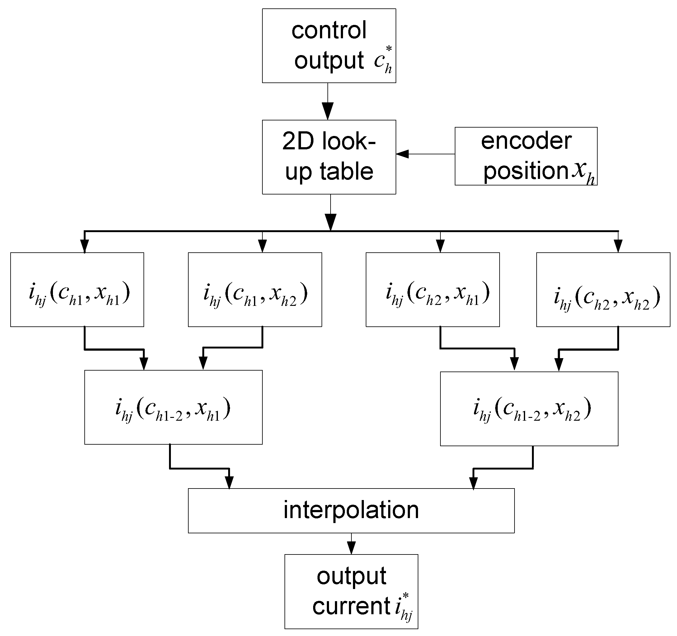
According to (2)–(6), force, current, and position are related in three dimensions, and a two-dimensional (2D) force–current–position look-up table for each axis is sufficient to describe the nonlinear force profile [24]. From the measurement or finite element analysis results, an inverse relationship between current, force, and position within one pole width can be derived [25]. For the implementation of the inverse force current position look-up tables, continuity and smoothness of the profile are more important than accuracy [26]. A relatively low 27 × 27 matrix is applied to build the look-up table for the force compensation values. To ensure smoothness, a two-dimensional linear interpolation scheme is implemented for the intermediate values.
Figure 3 demonstrates the procedure for obtaining the required current by the bi-linear interpolation method. Firstly, from the position input and control output , two pairs of data , and , in the look-up table are located. For each pair, a linear interpolation is done according to the ratio of , , and . As a result, two intermediate elements, and , can be obtained. Finally, the output current command is obtained by interpolating the two intermediate elements with and . The actual current output for each phase from either mover can then be obtained from the current control loop.
4. Complimentary Force Allocation
4.1. Constant Proportion Allocation
If we set the left point of spring1 as the zero point, we have
where and are the distance of the two movers according to the zero point, respectively, and and are the deformation displacement of spring1 and spring2, respectively. Then, we have
where is the spring elastic coefficient, and is the maximum force that either mover can provide. If and are the position references of the two movers, from Figure 3, we have
If we define as the displacement ratio of the two movers, then
Combining (9) and (10), the relationship of the force reference signals can be derived as
It is clear from (11) that the force reference is proportionally allocated according to the position of the two movers. From the above deductions
If the maximum position reference is defined as , according to (8)–(11), the constraint condition for the constant proportion scheme can be derived as
4.2. Constant Proportion Allocation with a Saturation Interval and Error Compensation
It is clear from the above deductions that the force from mover2 can be easily influenced by and the position reference signal . If is too small, is a small value and even the friction of mover2 may not be counteracted; if is large, the deformation of spring2 is severe and it may lead to total force fluctuations. Though this method can be easily implemented, the entire performance cannot be guaranteed, especially under extreme conditions either for a small or large . Since the position reference signal of mover2 determines the total force output at the zero point, a sectional function is proposed considering the extreme conditions. Meanwhile, the real-time position error from mover1 is regarded at the same time. The position reference for mover2 can thus be denoted in three sections as
with . For the first section, if the actual position of mover1 is small, is set as large to ensure a quick dynamic response. The second section is a proportional part and the actual position error of mover1 is considered. The third section is to guarantee that the deformation of spring2 is moderate so that force fluctuations can be avoided. It is clear that (14) can ensure a more flexible selection range of while it is not restricted by (13).
4.3. Variable Proportion
Although the above methods can improve the dynamic performance of the total force output at the zero point, the parameter selection for is determined by the ratio of , , maximum force, and position output. However, the adaptation to the variations of the force reference input is not considered. It can be found that the entire performance is determined by the force output of spring1 at the zero point, and meanwhile, mover1 alone cannot guarantee the precision. Therefore, we can make mover2 act in a compensation role for mover1. If we consider the friction from either mover to the stator and let , we have
By introducing the following coefficient,
and combining (15), we have
Since the force from spring1 and are the load to mover1, the introduction of is to let mover2 fully compensate for the load effect of mover1. It is clear from (14) and (15) that mover2 dynamically adapts to the real-time force output and position according to mover1.
5. Experimental Verification
The experimental force control setup is shown in Figure 4. The experiment is performed based on a real-time control platform of a dSPACE DS1104 board that is mounted onto a personal computer. The developed algorithm can be programmed with control parameters modified online in the Matlab/Simulink environment. The outer force control loop applies a sampling rate of 1 kHz. Commercial current amplifiers are employed to regulate the current loops with a sampling rate of 20 kHz. The current amplifiers are provided with an 80 V power supply. The current output for each phase is regulated based on the proportional-integral scheme, and it is fast enough to correct current errors in time before the outer loop starts [25]. Considering the power of the linear machine, the current limit value is set as 5 A. The linear magnetic encoders collect the real-time position information for mover1 and mover2 with a resolution of 1 µm. The zero point is assigned as the point where Spring1 connects to the fixture, and the left direction is defined as the positive direction.
Under the simple yet effective proportion-integral-differential (PID) control algorithm, the position response profiles for either mover under a no-load situation can be found in Figure 5. Due to the mass and inertia of the movers, the force reference input is a sinusoidal wave with an amplitude of 60 N and a frequency of 0.5 Hz. The positive direction for the two movers is the left direction. The control parameters can be adjusted in real-time to achieve a minimum dynamic error response profile [26]. Based on a trial and error basis, the proportional, integral, and differential gains are selected as = 3, = 0.0001, and = 0.0031, respectively. Though the dynamic error response profiles during positive and negative transitions are not symmetric, it can be concluded from Figure 5b that a dynamic error under ±0.3 N can be derived. Once the PID gains are determined, they are fixed for further experiment tests.
Now, spring1 is connected to mover1 and Figure 6 shows the dynamic force response waveforms. From Figure 6a, when the spring deformation displacement reaches about −57 mm, mover1 can no longer counteract the spring force and the experimental result shows that the maximum force output for mover1 does not exceed 57 N. The maximum dynamic force error reaches −2.4 N as shown in Figure 6b.
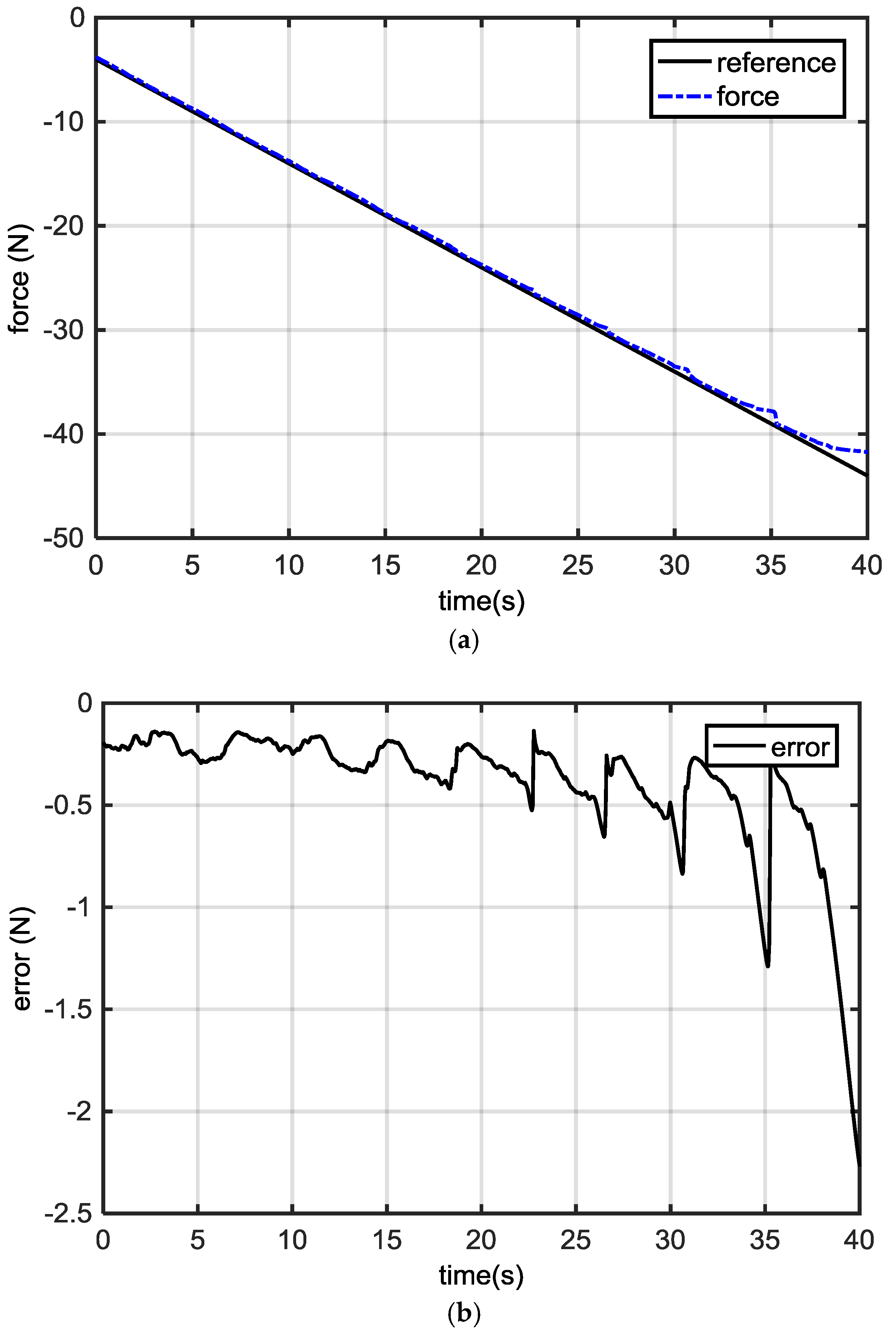
To further test the behavior of mover1, a unit ramp force signal is introduced. From Figure 7a, as the force command gradually increases, the actual force response of mover1 (blue dashed line) is always above the reference signal (black solid line). This means that the actual force output is always less than the force reference and mover1 is always in the state of insufficient output. The dynamic error waveform in Figure 7b also verifies that the actual force output never exceeds the force reference values, since the error response profiles are below zero. Meanwhile, there is exhibited force fluctuations and the period is about 4 mm, which conforms to the structure of the machine. If the force command exceeds 30 N, the performance deteriorates and the dynamic error values are more than 0.7 N. In order to ensure the system control accuracy, = 30 N is selected as the maximum output value for single movers.
From the constant proportion allocation strategy, the actual response and dynamic error waveforms are shown in Figure 8a,b, respectively. is selected as 1.9 with = 30 N. The dynamic error values fall into (−0.06 N, 0.2 N). Under this scheme, the dynamic force error is the largest at the initial stage; this is because at small force reference levels, the regulation effect is weak.
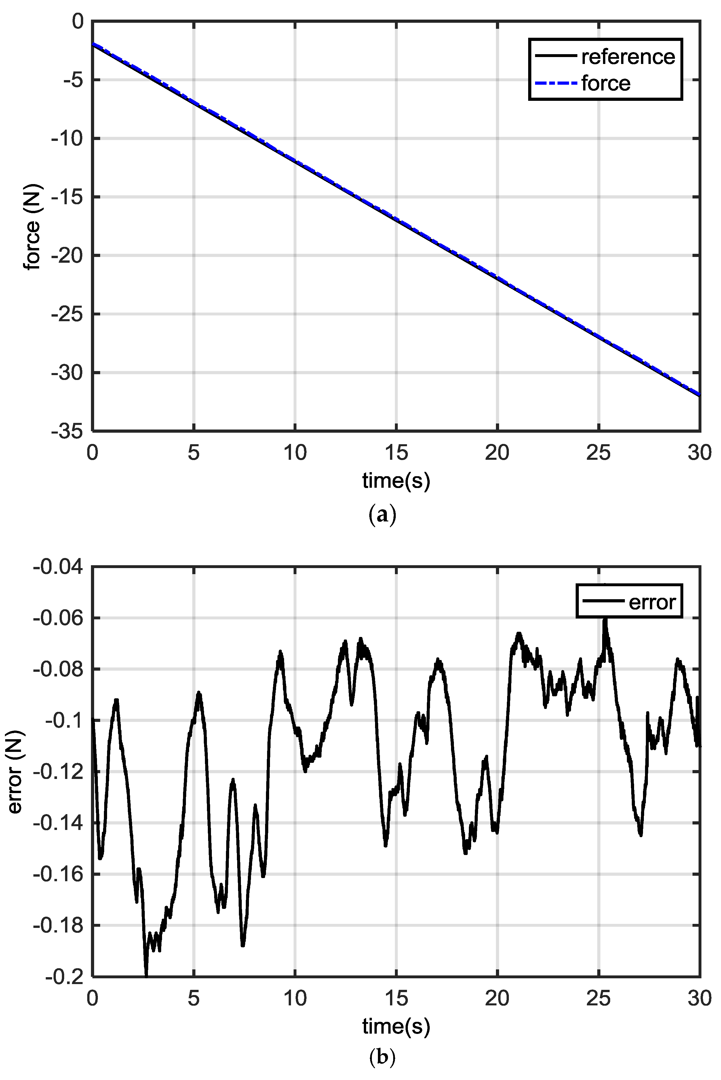
Based on the above two control strategies, the design of a constant proportional allocation strategy with a saturation interval and error compensation can guarantee the control accuracy in a certain range. is selected as 3.8 to enhance the regulatory effect. The actual response and dynamic error profiles are shown in Figure 9a,b, respectively. From Figure 9b, at the beginning, mover2 can provide a pulling force for mover1. This can effectively and rapidly reduce the total dynamic force error. As the force reference level increases, the regulation effect switches to the constant proportion allocation scheme. In order to avoid the instability of mover2 by an inappropriate deformation of spring2, a limit function is applied according to (14). The dynamic error can be controlled within the range of 0.051 mm and −0.06 mm.
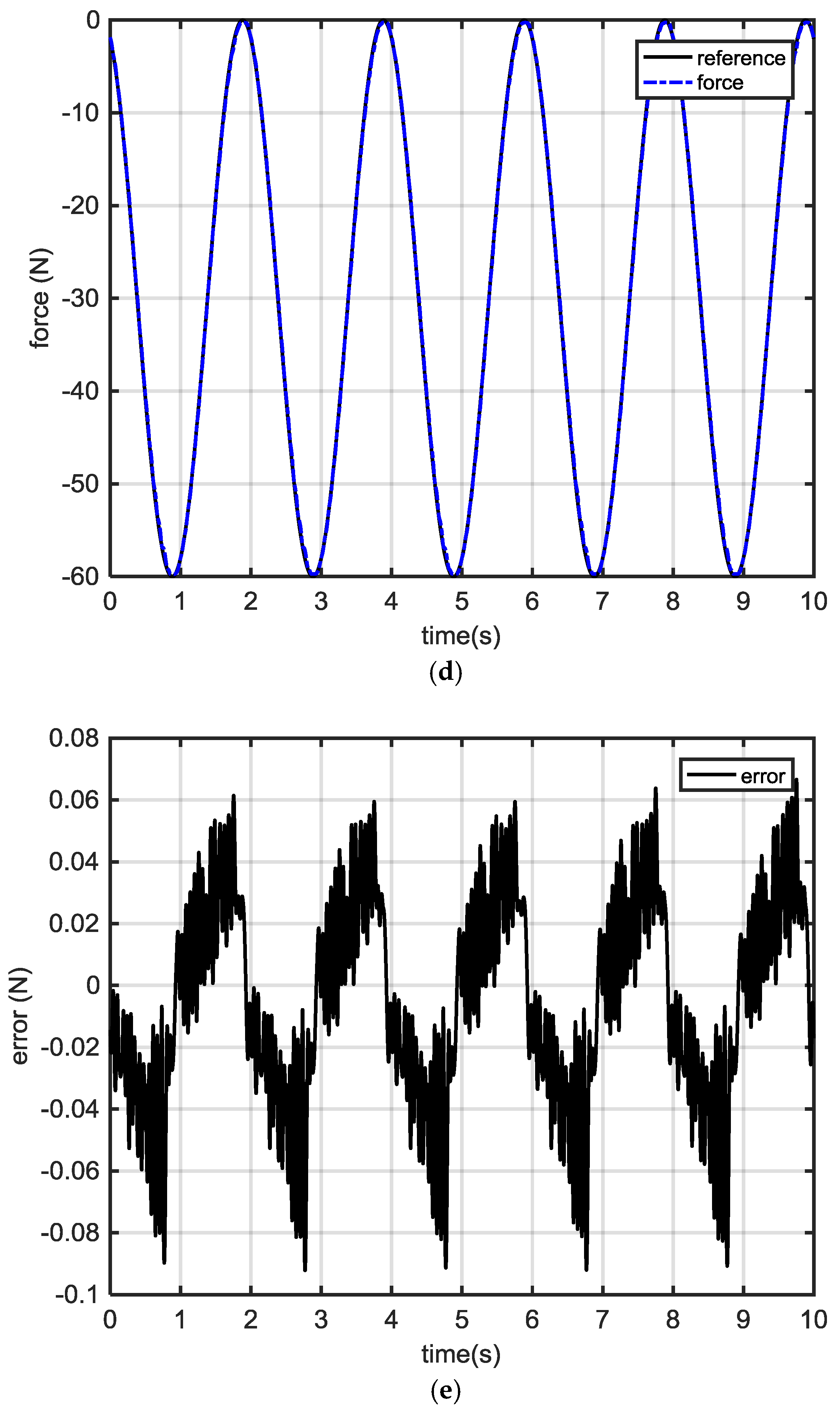
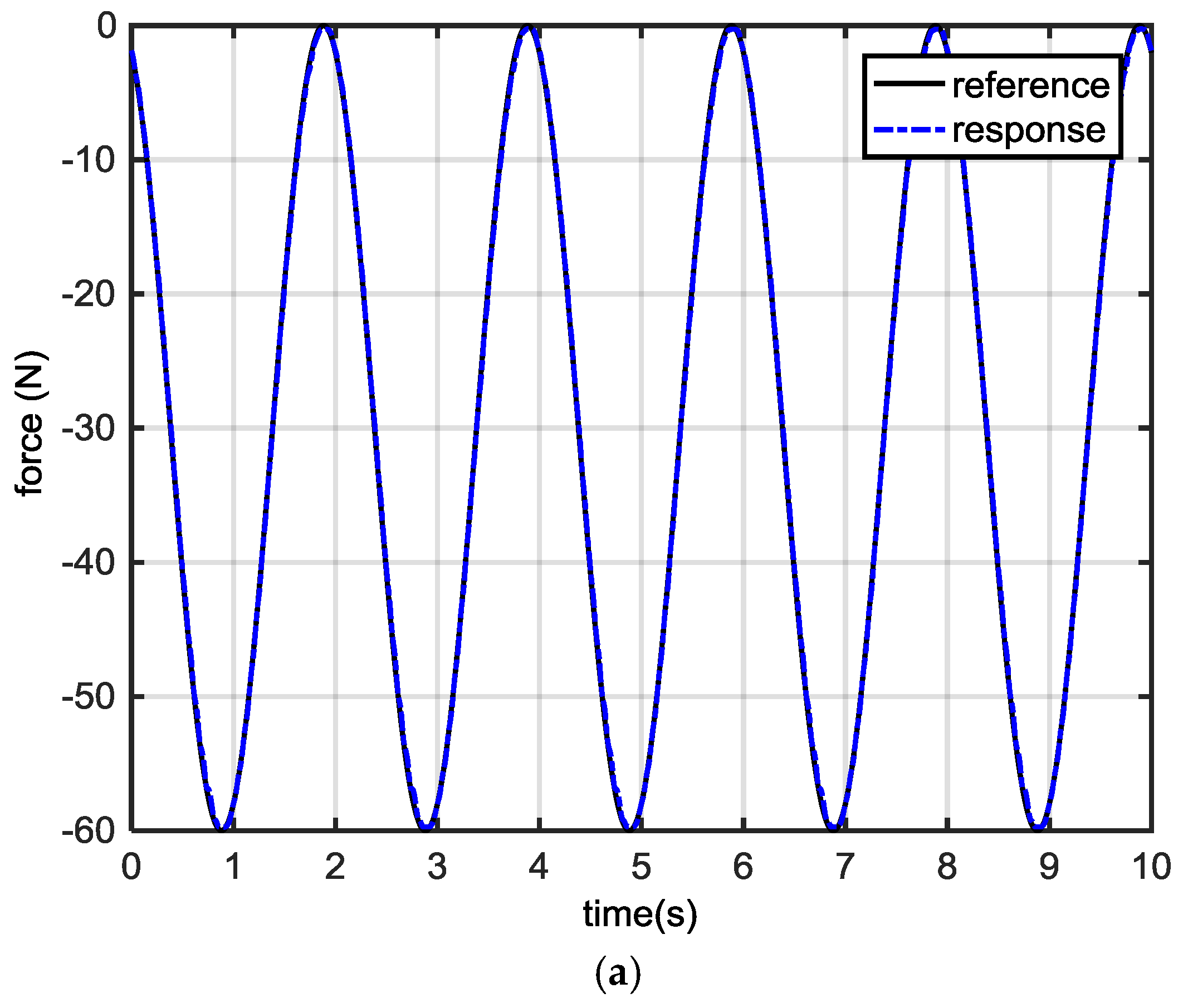
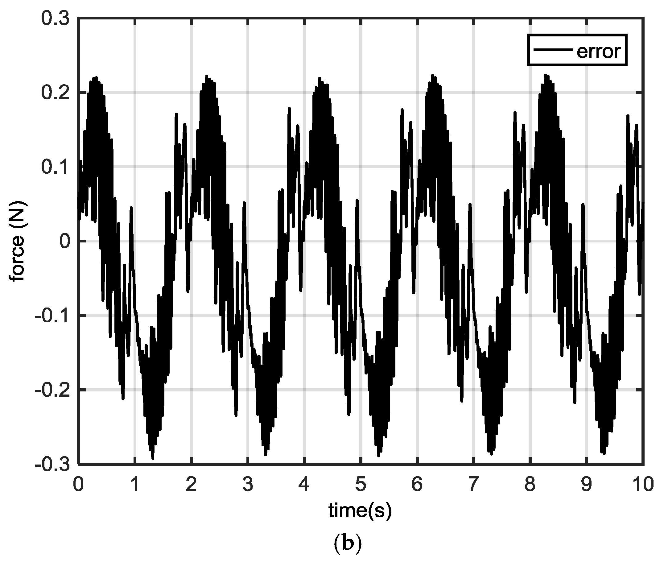
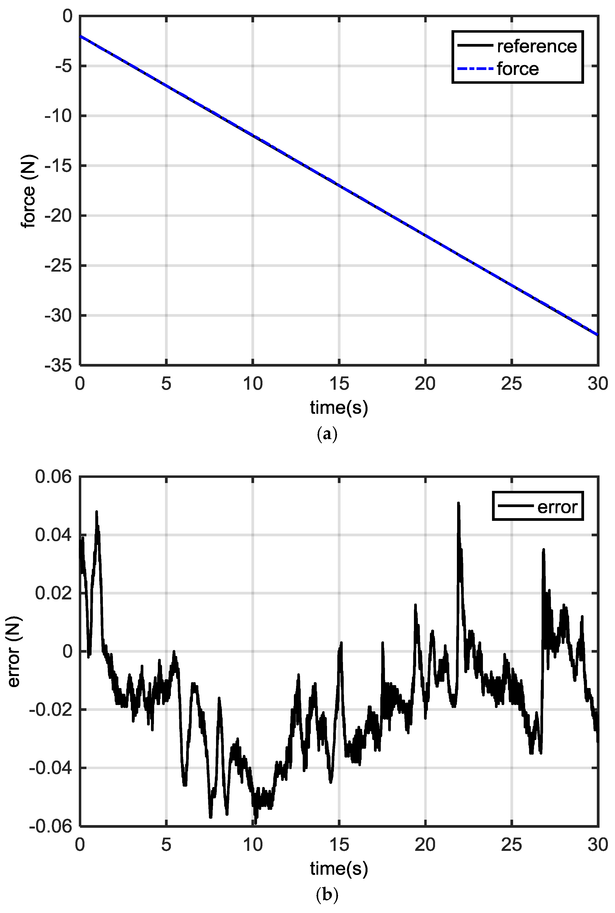
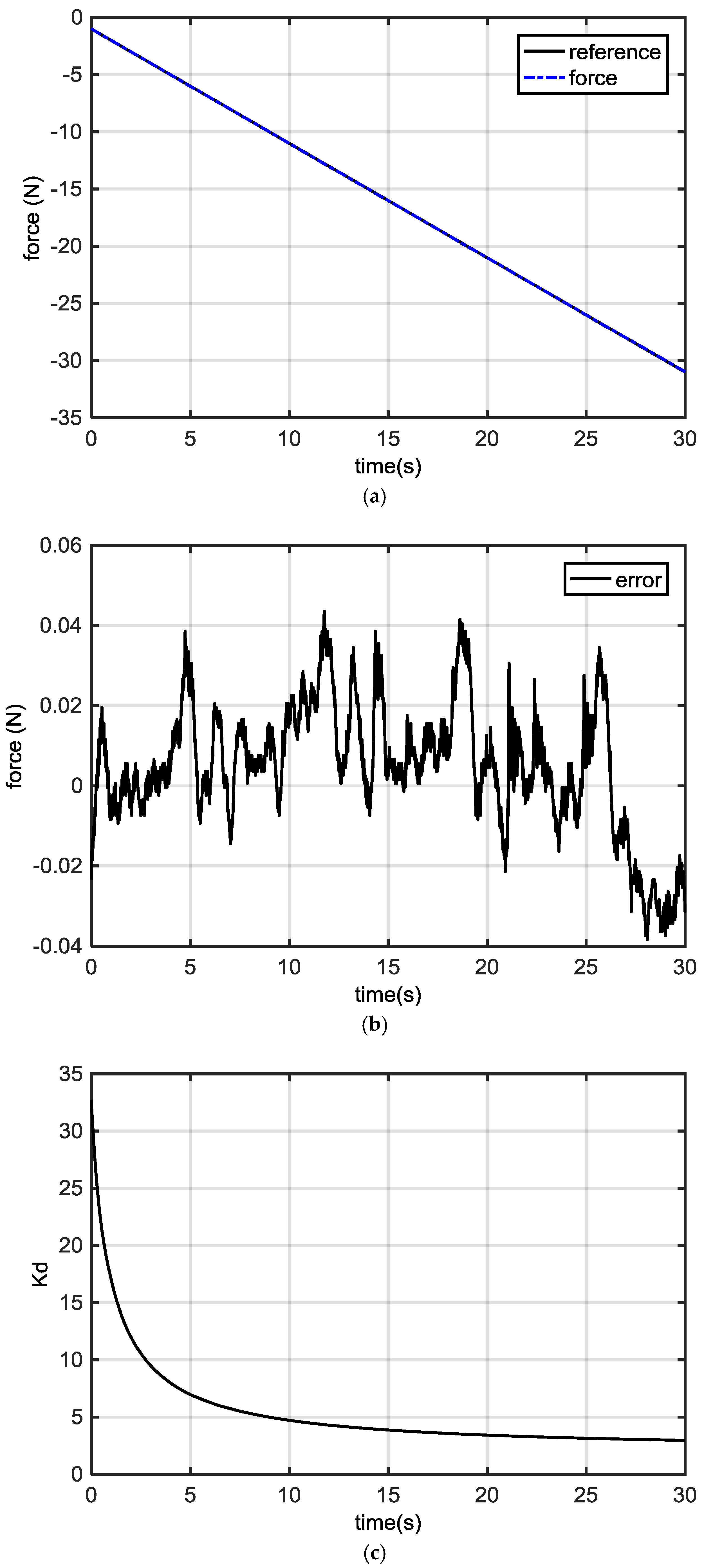
The variable proportion allocation strategy can effectively improve the system control accuracy. Figure 10a,b demonstrates the response and dynamic error profiles. Mover2 provides the required force for mover1 and helps mover1 overcome the friction force according to (15). It is clear that the dynamic force error can be controlled within the range of 0.044 mm to −0.04 mm. Figure 10c shows the variable proportion coefficient. Its large initial value values guarantee a quick decrease of force error values. The response under the sinusoidal force reference can be found in Figure 10d,e, respectively. It can be seen that a dynamic force error falling into 0.062 N and 0.091 N can be achieved under the variable proportion allocation strategy.
6. Conclusions and Discussion
To improve the force performance, this paper first attempts to improve the total force performance by the coordination force output of two movers from an integrated, dual-mover LSRM. Three force allocation strategies are investigated, including the constant proportion, constant proportion with a saturation interval and error compensation, and the variable proportion allocation methods. Through a theoretical and experimental analysis, the force control precision under the variable proportion allocation strategy is found to be the highest, since mover2 acts in a compensation role for mover1 in real-time. The constant proportion method is not suitable for extreme conditions at either a small or large . From the sectional function with a saturation interval and error compensation method, parameter is still restricted by the ratio of , , maximum force, and position output. Meanwhile, the adaptation to the variations of the force reference input is not considered.
Since each mover is controlled by the PID method, they exhibit asymmetric force response profiles during positive and negative transitions. This is mainly because the behaviors due to an unbalanced assembly, friction, or air gaps, etc. are not uniform. Further study is suggested to focus on advanced force control methodologies to annihilate the asymmetric performance. The idea of the cooperation of two linear movers to obtain a precise force control performance can be applied to multiple movers. In addition, the proposed force allocation schemes can also be applied to other types of LMs with different parameters, such as a linear synchronous permanent magnet machine. From the above analysis, it can be found that a more accurate total force control precision result can be derived if more movers can be introduced. It is expected that the proposed force allocation scheme from the cooperation of multiple LMs can be applied in those industrial manipulation and measurement areas that are required to follow a precise force profile.
Acknowledgments
This work was supported in part by the National Natural Science Foundation of China under Grant Nos. 51477103, 51577121, 11572248, 61690211, and 61403258. The authors also would like to thank the Guangdong and Shenzhen Governments under the Code of S2014A030313564, 2015A010106017, 2016KZDXM007, JCYJ20160308104825040, and JCYJ20170302145012329 for support.
Author Contributions
J. F. Pan conceived and wrote the main body of the paper, and Bo Zhang and Jianping Yuan designed the main body of the study. Li Qiu guided the system design, analyzed the data, and revised the manuscript. Weiyu Wang performed the simulations and experiments. Xiaoyu Wu and Eric Cheng helped to revise the paper.
Conflicts of Interest
The authors declare no conflict of interest.
References
- Lim, H.S.; Krishnan, R.; Lobo, N.S. Design and Control of a Linear Propulsion System for an Elevator Using Linear Switched Reluctance Motor Drives. IEEE Trans. Ind. Electron. 2008, 55, 534–542. [Google Scholar] [CrossRef]
- Ge, B.; Almeida, A.T.; Ferreira, F.J.T.E. Design of Transverse Flux Linear Switched Reluctance Motor. IEEE Trans. Magn. 2009, 45, 113–119. [Google Scholar]
- Chung, S.U.; Kim, J.M. Double-Sided Iron-Core PMLSM Mover Teeth Arrangement Design for Reduction of Detent Force and Speed Ripple. IEEE Trans. Ind. Electron. 2016, 63, 3000–3008. [Google Scholar] [CrossRef]
- Hasanien, H.M.; Abd-Rabou, A.S.; Sakr, S.M. Design Optimization of Transverse Flux Linear Motor for Weight Reduction and Performance Improvement Using Response Surface Methodology and Genetic Algorithms. IEEE Trans. Energy Convers. 2010, 25, 598–605. [Google Scholar] [CrossRef]
- Gan, W.C.; Cheung, N.C.; Li, Q. Position control of Linear Switched Reluctance Motors for High-precision Applications. IEEE Trans. Ind. Appl. 2003, 39, 1350–1362. [Google Scholar]
- Zhao, S.W.; Cheung, N.C.; Gan, W.; Yang, J.M. High-precision Position Control of a Linear-switched Reluctance Motor using a Self-tuning Regulator. IEEE Trans. Power Electron. 2010, 25, 2820–2827. [Google Scholar] [CrossRef]
- Lee, S.G.; Kim, S.A.; Saha, S.; Zhu, Y.W.; Cho, Y.H. Optimal Structure Design for Minimizing Detent Force of PMLSM for a Ropeless Elevator. IEEE Trans. Magn. 2014, 50. [Google Scholar] [CrossRef]
- Ravanji, M.H.; Nasiri-Gheidari, Z. Design Optimization of a Ladder Secondary Single-Sided Linear Induction Motor for Improved Performance. IEEE Trans. Energy Convers. 2015, 30, 1595–1603. [Google Scholar] [CrossRef]
- Pourmoosa, A.A.; Mirsalim, M. Design Optimization, Prototyping, and Performance Evaluation of a Low-Speed Linear Induction Motor With Toroidal Winding. IEEE Trans. Energy Convers. 2015, 30, 1546–1555. [Google Scholar] [CrossRef]
- Enrici, P.; Dumas, F.; Ziegler, N.; Matt, D. Design of a High-Performance Multi-Air Gap Linear Actuator for Aeronautical Applications. IEEE Trans. Energy Convers. 2016, 31, 896–905. [Google Scholar] [CrossRef]
- Hasanien, H.M. Particle Swarm Design Optimization of Transverse Flux Linear Motor for Weight Reduction and Improvement of Thrust Force. IEEE Trans. Ind. Electron. 2011, 58, 4048–4056. [Google Scholar] [CrossRef]
- Pan, J.F.; Cheung, N.C.; Zou, Y. An Improved Force Distribution Function for Linear Switched Reluctance Motor on Force Ripple Minimization with Nonlinear Inductance Modeling. IEEE Trans. Magn. 2012, 48, 3064–3067. [Google Scholar] [CrossRef]
- Miller, T.J.E. Switched Reluctance Motors and Their Control; Oxford University Press: Oxford, MI, USA, 1993; pp. 25–28. [Google Scholar]
- Byeong-Seok, L.; Han-Kyung, B.; Praveen, V.; Krishnan, R. Design of a Linear Switched Reluctance Machine. IEEE Trans. Ind. Appl. 2000, 36, 1571–1580. [Google Scholar]
- Shi, Y.; Huang, J.; Yu, B. Robust tracking control of networked control systems Application to a networked DC motor. IEEE Trans. Ind. Electron. 2013, 60, 5864–5874. [Google Scholar] [CrossRef]
- Karimi, H.; Vaez-Zadeh, S.; Salmasi, F.R. Combined Vector and Direct Thrust Control of Linear Induction Motors with End Effect Compensation. IEEE Trans. Energy Convers. 2016, 31, 196–205. [Google Scholar] [CrossRef]
- Zhang, H.; Shi, Y.; Mehr, A.S. Robust static output feedback control and remote PID design for networked motor systems. IEEE Trans. Ind. Electron. 2011, 58, 5396–5405. [Google Scholar] [CrossRef]
- Xu, L.; Lin, M.; Fu, X.; Liu, K.; Guo, B. Analytical Calculation of the Magnetic Field Distribution in a Linear and Rotary Machine with an Orthogonally Arrayed Permanent Magnet. Energies 2017, 10, 493. [Google Scholar] [CrossRef]
- Pan, J.F.; Zou, Y.; Cao, G. An Asymmetric Linear Switched Reluctance Motor. IEEE Trans. Energy Convers. 2013, 28, 444–451. [Google Scholar] [CrossRef]
- Bo, Z.; Pan, J.F.; Jianping, Y.; Wu, R.; Li, Q.; Jianjun, L.; Honghua, D. Tracking control with zero phase-difference for linear switched reluctance machines network. Energies 2017, 10, 949. [Google Scholar] [CrossRef]
- Masoudi, S.; Feyzi, M.R.; Sharifian, M.B.B. Force ripple and jerk minimisation in double sided linear switched reluctance motor used in elevator application. IET Electr. Power Appl. 2016, 10, 508–516. [Google Scholar] [CrossRef]
- Qiu, L.; Shi, Y.; Pan, J.; Zhang, B.; Xu, G. Collaborative tracking control of dual linear switched reluctance machines over communication network with time delays. IEEE Trans. Cybern. 2017, 47, 4432–4442. [Google Scholar] [CrossRef] [PubMed]
- Du, Y.; Yang, G.; Quan, L.; Zhu, X.; Xiao, F.; Wu, H. Detent force reduction of a C-core linear flux-switching permanent magnet machine with multiple additional teeth. Energies 2017, 10, 318. [Google Scholar] [CrossRef]
- Cheema, M.A.M.; Fletcher, J.E.; Xiao, D.; Rahman, M.F. A Linear Quadratic Regulator-Based Optimal Direct Thrust Force Control of Linear Permanent-Magnet Synchronous Motor. IEEE Trans. Ind. Electron. 2016, 63, 2722–2733. [Google Scholar] [CrossRef]
- Pan, J.; Meng, F.; Cao, G. Decoupled Control for Integrated Rotary–linear Switched Reluctance Motor. IET Electr. Power Appl. 2014, 8, 199–208. [Google Scholar] [CrossRef]
- Brauer, H.J.; Hennen, M.D.; de Doncker, R.W. Control for Polyphase Switched Reluctance Machines to Minimize Torque Ripple and Decrease Ohmic Machine Losses. IEEE Trans. Power Electron. 2012, 27, 370–378. [Google Scholar] [CrossRef]
Figure 1.
(a) Machine topology of the linear machine (b) picture of the dual-mover linear switched reluctance machine (LSRM).
Figure 1.
(a) Machine topology of the linear machine (b) picture of the dual-mover linear switched reluctance machine (LSRM).
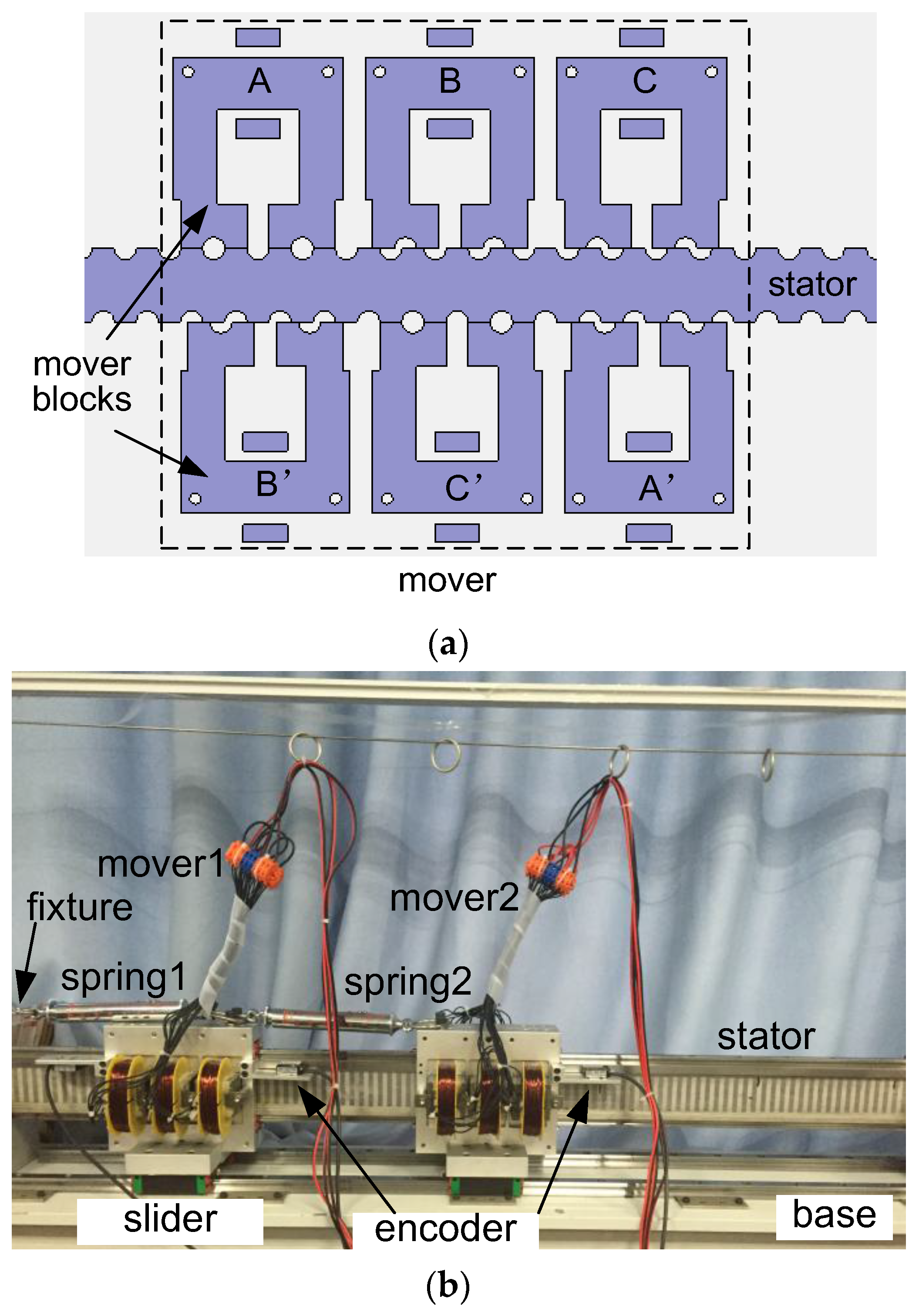
Figure 2.
Diagram of the complimentary force control scheme.

Figure 3.
Flow chart of current command derivation by interpolation. 2D: two-dimensional.

Figure 4.
Experimental force control setup.
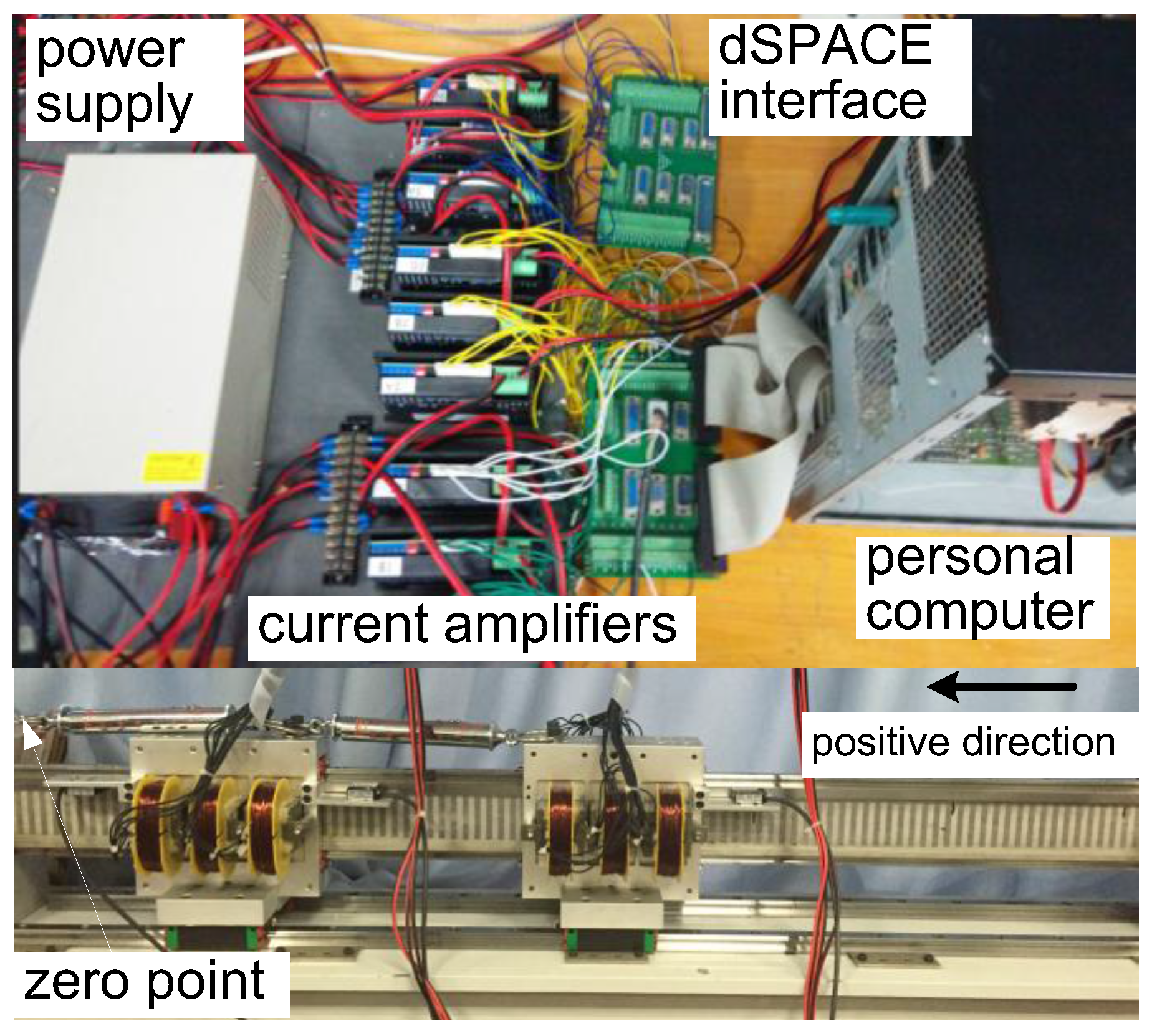
Figure 5.
(a) Mover response profiles without load (b) error response profile.


Figure 6.
(a) Response profiles of mover1 and (b) the error response waveform with spring1.
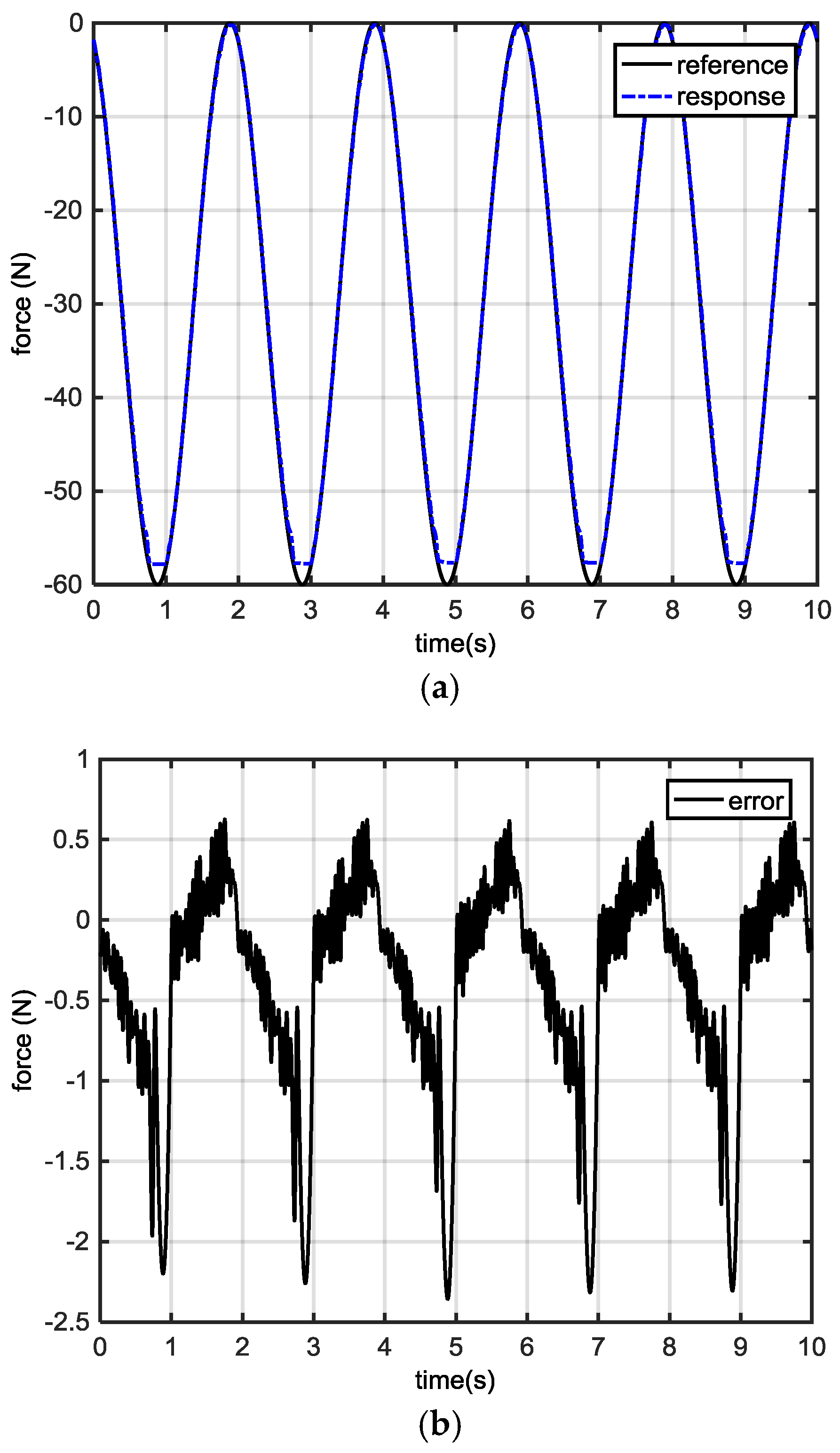
Figure 7.
Dynamic response under unit ramp (a) force profiles (b) error waveforms.

Figure 8.
Dynamic response under the constant proportion allocation scheme: (a) force profiles; (b) error waveforms.
Figure 8.
Dynamic response under the constant proportion allocation scheme: (a) force profiles; (b) error waveforms.

Figure 9.
Dynamic response under constant proportion allocation with a saturation interval and error compensation scheme: (a) force profiles; (b) error waveforms.
Figure 9.
Dynamic response under constant proportion allocation with a saturation interval and error compensation scheme: (a) force profiles; (b) error waveforms.

Figure 10.
Dynamic response profiles under variable proportion: (a) force profiles from the unit ramp; (b) error waveforms from the unit ramp; (c) Kd; (d) force profiles from the sinusoidal reference; (e) error waveforms from the sinusoidal reference.
Figure 10.
Dynamic response profiles under variable proportion: (a) force profiles from the unit ramp; (b) error waveforms from the unit ramp; (c) Kd; (d) force profiles from the sinusoidal reference; (e) error waveforms from the sinusoidal reference.


Table 1.
Major Specifications of the dual-mover LSRM.
| Parameter | Value |
|---|---|
| Rated power | 250 W |
| Mass of the mover1 and 2 | 5 kg |
| Pole width | 6 mm |
| Pole pitch | 12 mm |
| Phase resistance | 2 Ohm |
| Air gap length | 0.3 mm |
| Number of turns | 250 |
| Stator length | 2000 mm |
| Stack length | 50 mm |
| Elastic coefficient | 1 N/mm |
| Rated Voltage | 50 V |
| Mass of the mover1 and 2 | 5 kg |
Table 2.
Multi-phase excitation scheme for each mover.
| Range (mm) | Positive Control Output Command | Negative Control Output Command |
|---|---|---|
| 0–2 mm | | |
| 2–4 mm | | |
| 4–6 mm | , | |
| 6–8 mm | , | |
| 8–10 mm | , | |
| 10–12 mm | , |
© 2017 by the authors. Licensee MDPI, Basel, Switzerland. This article is an open access article distributed under the terms and conditions of the Creative Commons Attribution (CC BY) license (http://creativecommons.org/licenses/by/4.0/).
Share and Cite
MDPI and ACS Style
Pan, J.F.; Wang, W.; Zhang, B.; Cheng, E.; Yuan, J.; Qiu, L.; Wu, X. Complimentary Force Allocation Control for a Dual-Mover Linear Switched Reluctance Machine. Energies 2018, 11, 23. https://doi.org/10.3390/en11010023
AMA Style
Pan JF, Wang W, Zhang B, Cheng E, Yuan J, Qiu L, Wu X. Complimentary Force Allocation Control for a Dual-Mover Linear Switched Reluctance Machine. Energies. 2018; 11(1):23. https://doi.org/10.3390/en11010023
Chicago/Turabian StylePan, J. F., Weiyu Wang, Bo Zhang, Eric Cheng, Jianping Yuan, Li Qiu, and Xiaoyu Wu. 2018. "Complimentary Force Allocation Control for a Dual-Mover Linear Switched Reluctance Machine" Energies 11, no. 1: 23. https://doi.org/10.3390/en11010023
Note that from the first issue of 2016, this journal uses article numbers instead of page numbers. See further details here.