Article

Research on Strategies and Methods Suppressing Permanent Magnet Demagnetization in Permanent Magnet Synchronous Motors Based on a Multi-Physical Field and Rotor Multi-Topology Structure

1
School of Electrical Engineering, Beijing Jiaotong University, Beijing 100044, China
2
School of Electrical Engineering and Automation, Harbin Institute of Technology, Harbin 150001, China
*
Author to whom correspondence should be addressed.
Energies 2018, 11(1), 40; https://doi.org/10.3390/en11010040
Submission received: 24 November 2017 / Revised: 19 December 2017 / Accepted: 21 December 2017 / Published: 25 December 2017

Abstract

:
In this paper, a permanent magnet synchronous motor (PMSM) with sleeves on the rotor outer surface is investigated. The purpose of sleeves is to fix the permanent magnets and protect them from being destroyed by the large centrifugal force. However, the sleeve material characteristics have a great influence on the PMSM, and therewith, most of the rotor eddy-current losses are generated in the rotor sleeve, which could increase the device temperature and even cause thermal demagnetization of the magnets. Thus, a sleeve scheme design with low eddy-current losses is necessary, and a method suppressing the local temperature peak of permanent magnets is presented. The 3-D electromagnetic finite element model of a 12.5 kW, 2000 r/min PMSM with a segmented sleeve is established, and the electromagnetic field is calculated by using the finite element method. The results show the effectiveness of the presented method in reducing the eddy current losses in the rotor. Using the thermal method, it can be found that the maximum temperature position and zone of permanent magnet will change. Thus, some strategies are comparatively analyzed in order to obtain the change rule of the position and zone. The obtained conclusions may provide a useful reference for the design and research of PMSMs.

1. Introduction

The permanent magnet synchronous motor (PMSM), which integrates the advantages of high-power density, high efficiency, light weight, easy maintenance, and good reliability, has been widely used in commerce, industry, transportation, and so on [1,2], thus it attracts the interest of many researchers from the international electrotechnical field [3,4,5].
Generally, because the tensile capability of permanent magnets is poor, they can be destroyed by a large centrifugal force. A rotor sleeve could provide a suitable pre-pressure and reduce the influence of the centrifugal force on the permanent magnets. Therefore, a rotor sleeve often has been coated on the rotor outer surface to fix the magnets. However, eddy-current losses, caused by harmonic magnetic field, will appear in the rotor sleeve. This may increase the temperature of the PMSM and even cause the magnets to be demagnetized, which could not only decrease the PMSM performance, but also shorten the working life of the machine [6,7,8]. Thus, it is very significant to seek measures for reducing the eddy-current losses in the rotor sleeve and permanent magnets.
There are many possible measures for reducing the eddy-current losses in the rotor. It is well known that carbon fiber has advantages of high strength, low conductivity, good performance, and simple processing. A machine with a carbon fiber sleeve has been researched [9,10,11], and the influence of carbon fiber on the electromagnetic and temperature fields of the machine was calculated. Kirtley, and Lovelace, and Zhu et al, have tested prototypes with an alloy rotor sleeve [12,13]. Copper plating, has high conductivity, and the advantages of copper sleeves in reducing eddy-current losses was presented [14,15], and the influence of copper layer thickness on rotor eddy-current losses and temperature distribution was analyzed. In [16], the electromagnetic and temperature fields of machine with different sleeve materials were researched.
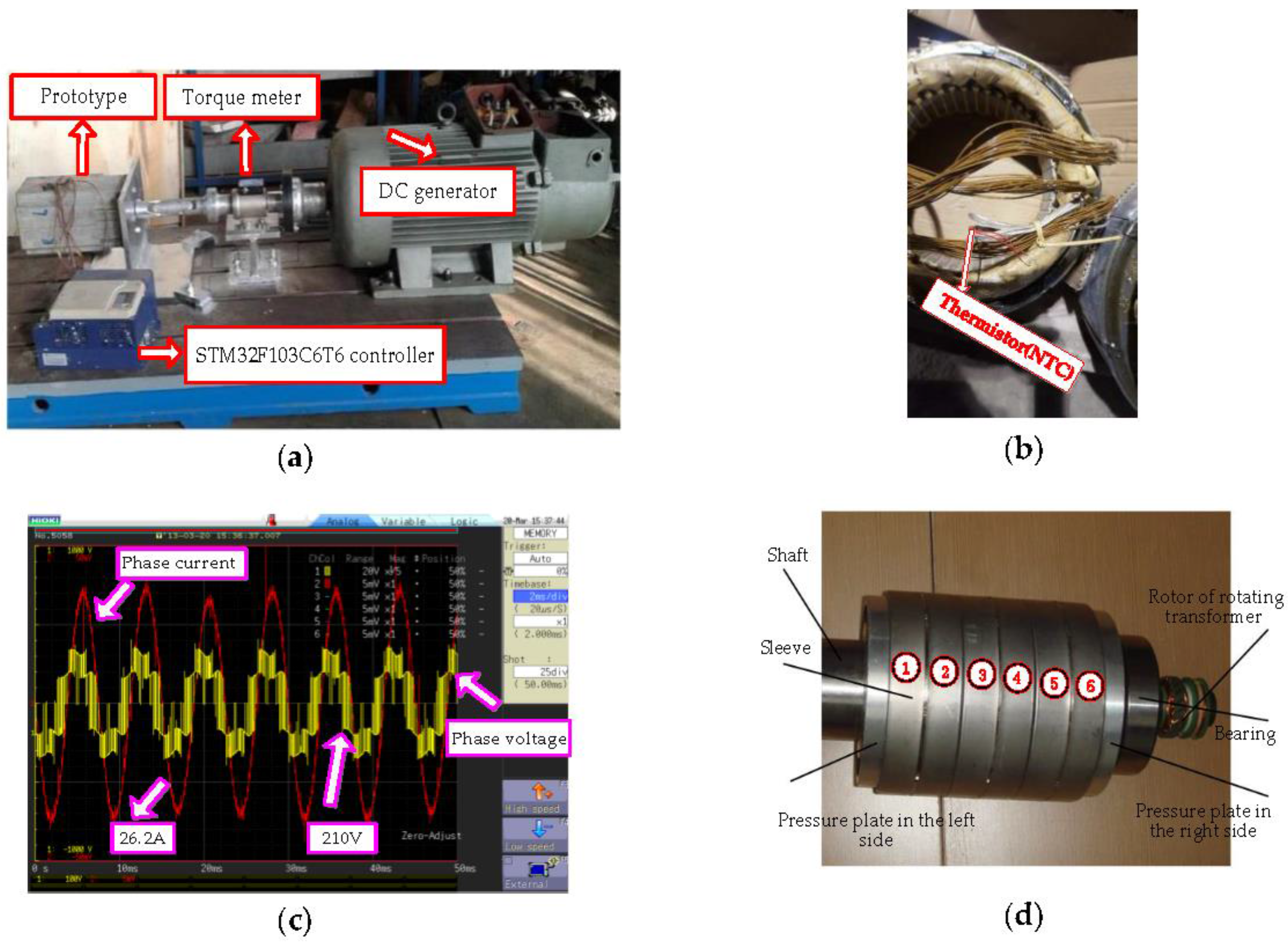
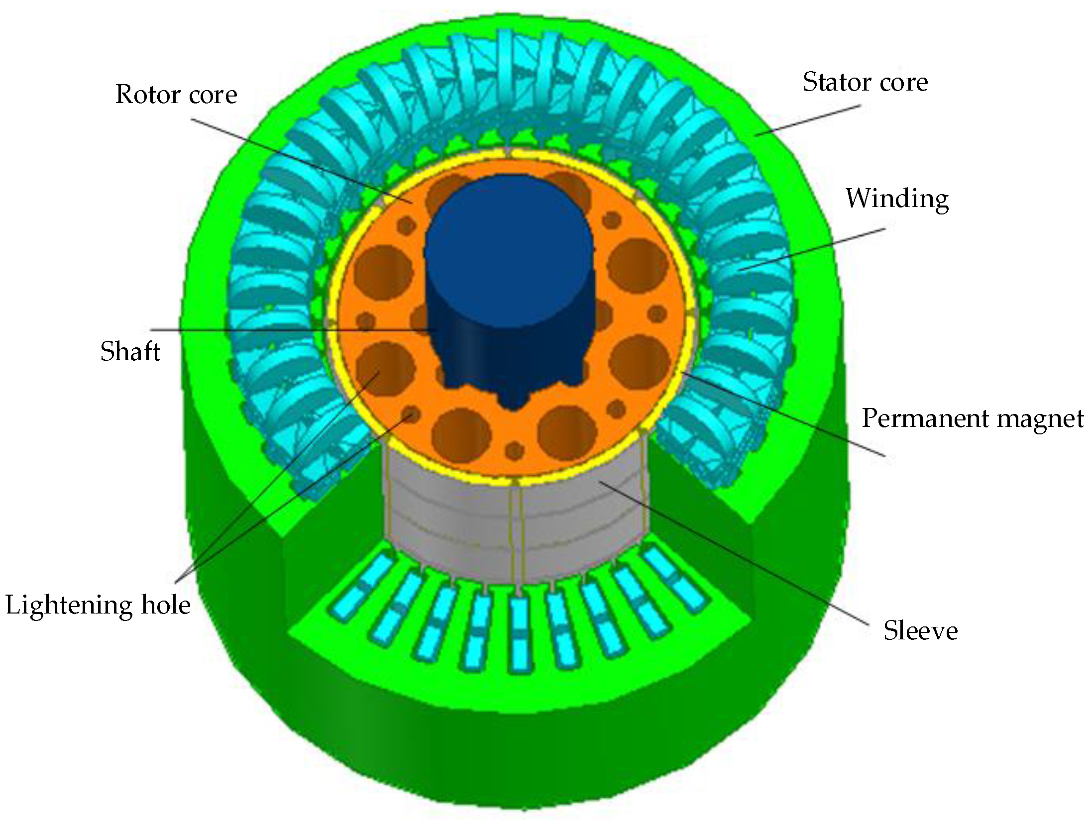
In this paper, taking a 12.5 kW, 2000 r/min PMSM with a 0.2 mm stainless steel sleeve as the study object, a method suppressing the local temperature peak of permanent magnets to solve the problem of the high temperature in the rotor is presented. Firstly, 3-D transient electromagnetic field mathematical and physical models are established, and then the electromagnetic field in the PMSM is calculated under rated-load conditions by using the time-stepping finite element method. Next, the losses in different part of PMSM are applied to the thermal field as heat sources, combined with the 3-D temperature field model, and the influence of the presented method on temperature distribution is studied. The calculated results show the effectiveness of the presented method in reducing the eddy-current losses and temperature in the rotor. In this process, it can be found that the position and zone of permanent magnet maximum temperature can change. Thus, in order to obtain the change rule of the maximum temperature position and zone, three designs are presented based on Multi- Physical Field. The obtained conclusions may provide a theoretical basis for the design and optimization of PMSMs, and in addition, they can also provide a useful reference for thermal studies on permanent magnet motors.

2. Electromagnetic Field and Thermal Analysis

2.1. Parameters and Structure of PMSM

Figure 1 shows the prototype PMSM experimental platform and test results operating at rated speed (2000 r/min) and rated load (R = 0.32 Ω and cos φ = 0.79). The PMSM studied in this paper was a SPMSM driven by a STM32F103C6T6 controller.
The frequency of the CPU of the STM32F103C6T6 was 72 MHz. The IGBT-inverter with double closed loop control system was applied to the test PMSM. In the process, the proportional parameters of speed loop and current loop of the STM32F103C6T6 controller were chosen as 3, 2, and their integral parameters were chosen as 0.3, 0.8 in the tests, respectively. While the tests were being carried out, the reference DC-link voltage was 500 V, and the sample frequency of the signal carrier was 10 kHz. The rotor magnetic field was excited by a PM (N33SH), whose remanence (Br) and coercivity (Hc) is 1.1 T, 838 kA/m, respectively, and the limited working temperature is 150 °C. Meanwhile, the conductivity is 6.25 × 10⁵ S/m, and it is divided into three segments in the axial direction. To prevent damage to the rotor’s permanent magnets due to the large rotational centrifugal forces, the sleeves, which are coated on the outer surface of permanent magnets, adopt a stainless steel material and are divided into six segments in the axial direction, moreover, the number of each segment sleeve is shown in Figure 1d. The conductivity and thermal conductivity of the stainless steel sleeve are 1.1 × 10⁶ S/m and 59 W/m·K, respectively. The basic parameters of the PMSM are listed in Table 1.
A thermistor (NTC) was buried in the end winding, which is shown in Figure 1b. The resistance value of the thermistor (NTC) could be obtained by a multimeter, then, according to the converted ration between the thermistor (NTC) and the temperature, the maximum temperature of the winding was measured.
Generally, the hysteresis loss is much larger than the eddy- current loss below the base speed, and the eddy-current loss in the stator can be ignored [17]. Therefore, in this paper, the stator core loss is obtained according to (1):
{ P F e = P h + P a P h = k = 1 N P e k = k = 1 N K h ( B k f k ) 2 P a = k = 1 N P a k = k = 1 N K a ( B k f k ) 3 2
where, Ph is the hysteresis loss, Pa is the additional loss, Kh is hysteresis loss coefficient, Ka is the additional loss, Bk is the amplitude of k harmonic magnetic density in stator core, fk is the frequency of k harmonic magnetic density, N is the harmonics times. In this paper, through a least squares fitting method, Kh = 200, Ka = 0.865. The eddy-current losses in the rotor surface can be calculated in a cycle as follows:
P i = 1 T i i = 1 k J i 2 Δ i σ r 1 l t d t
where, Pi denotes the rotor eddy-current losses in permanent magnet or sleeve (in watts), Ji is the current density in each element (in amperes per square meter), Δi is the element area (in square meters), σr is the conductivity of the eddy current zone (in Siemens per meter), lt is the rotor axial length (in meters), Ti is the cycle of time.
In order to simplify the analysis during the electromagnetic research, the following assumptions are proposed:
(1)
The variation of the permeability and conductivity for the materials with temperature is ignored.
(2)
The skin effect of the stator winding is ignored.
(3)
The influence of the displacement current is ignored.
Based on the above assumptions, according to Maxwell equations, the equations of the magnetic vector in the solution domain can be derived, as follows:
{ Ω : { y { 1 μ ( A y x A x y ) } z { 1 μ ( A x z A z x ) } = J x σ d A x d t z { 1 μ ( A z y A y z ) } x { 1 μ ( A y x A x y ) } = J y σ d A y d t x { 1 μ ( A x z A z x ) } y { 1 μ ( A z y A y z ) } = J z σ d A z d t S :   A = 0
where, A is magnetic vector potential, A = [Ax Ay Az]T, J is the source current density, J = [Jx Jy Jz]T, Ω is the calculation region, S is the Dirichlet boundary condition, μ is magnetic permeability, σ is electrical conductivity.
Based on the structure and size of PMSM, a 3-D transient electromagnetic field calculation model can be established. In order to more clearly see the machine model structure, one eighth of the stator core and winding model is removed, as shown in Figure 2.
By using the finite-element method, the phase voltage and current of PMSM were calculated at rated load of 60 N·m, and the phase voltage, the phase current, the losses in different parts of PMSM are compared with the test data in Table 2. It can prove that the calculated results are in good agreement with the PMSM test data.

2.2. Thermal Analysis of PMSM

If a permanent magnet motor works at a high temperature for a long time, the performance and reliability of machine may be affected and even reduce the operating life. Therefore, it is of great significance [18] to explore some schemes for decreasing the rotor temperature by the temperature field analysis of the machine. To simplify the analysis during the calculation process, the following assumptions are proposed.
(1)
The influences of the temperature on material conductivity and permeability are ignored.
(2)
The solid parts in the PMSM are contacted very well, and the contacting thermal resistance is ignored.
(3)
Considering the effect of the end winding model crossing, assuming the end winding heat source is equal to the slot winding. The heat transfer of the air in the air gap, which is turbulence, is equivalent to the static coefficient of thermal conductivity. The static coefficient of thermal conductivity can be obtained according to [19]:
λ g = 0.069 η 2.9084 R e 0.4614 I n ( 3.33336 η )
where, λg is the static coefficient of thermal conductivity, γ is the radius ratio, η = r 0 / R i , r 0 is the rotor outer diameter, Ri is the stator inner diameter, Re is the Reynolds number.
The end of PMSM is equipped with a fan, whose inlet flow speed is kept at 2.74 m/s, and there is no ventilation system in the machine. Therefore, the heat coefficient [20] of the frame surface can be calculated using Equation (5):
α = 14 ( 1 + 0.5 v ) 3 θ 25
where, α is heat coefficient of frame surface, θ is outer surface temperature, ν is the flow speed of the frame inner wall.
3-D steady state heat transfer equation of PMSM can be shown as follows:
{ Ω : x ( k x T x ) + y ( k y T y ) + z ( k z T z ) = q v S 1 : k T n = α ( T T f )
where, kx, ky and kz is thermal conductivity in the x, y and z directions, respectively, qν is the heat resource density, T is temperature of any position in solving region (in °C), n is unit normal vector on the surface, α is the heat transfer coefficient of the solving boundary, Tf is the ambient temperature, S 1 is the frame surface, Ω is the calculation region.
Based on the above analysis, 3-D temperature field finite element analysis model of PMSM can be given, as shown in Figure 3, which has an ambient temperature of 10 °C and an inlet flow of 2.74 m/s. By finite element method, the whole region 3-D temperature distribution of PMSM operating at rated speed (2000 r/min) and rated load (R = 0.32 Ω and cos φ = 0.79) is obtained.
In this paper, the thermal performance of a PMSM operating with rated load (60 N·m) was tested, by using the test bed shown in Figure 1. The temperatures of stator winding, frame, and permanent magnet were measured by thermistors (negative temperature coefficient) with an accuracy of 0.1 °C. The comparisons of the measured maximum temperature with the calculated value are shown in Table 3, from which it can be seen that the calculated results are closed to the measured data under rated condition, inferring that the thermal analysis is credible.
According to calculation and analysis, it can be known that the rotor temperature is the highest in whole machine region, and the eddy current loss in the sleeve is the direct reason causing the high temperature of the rotor. The temperatures of permanent magnets and sleeves, which are the parts most seriously affected by the temperature, are given in Figure 4.
From Figure 4, it can be found that, because the sleeves are coated on the outer surface of permanent magnets, their temperature distribution is almost the same. The maximum temperature is 99 °C, and it is distributed the position of the circumferential two ends and close to the middle of the rear cover. Moreover, the temperature at the air inlet position is lower compared with the air outlet position, the axial temperature difference could reach 2.5 °C. The reason is mainly due to two aspects: firstly, the eddy current loss in the sleeve is mainly concentrated in the sleeve middle and close to the rear cover. In addition, the front cover is equipped with a fan, which can play a role in decreasing the temperature.

3. Research Suppressing Permanent Magnet Local Maximum Temperature

Through the above analysis, it can be known that the maximum temperature of the PMSM appears at the position of the permanent magnets. A high temperature could cause thermal demagnetization of permanent magnets and even endanger the safe operation of the PMSM. Therefore, it is necessary to devise a strategy to decrease the temperature of permanent magnets.
There are two main reasons which can affect the temperature distribution: the one is heat source distribution, the other one is the cooling mode. Through calculation and analysis, it can be known that the temperature of permanent magnets is low at the two ends and high in the middle. Thus, in this paper, from the point of view of improving the heat source distribution, a method for suppressing the permanent magnet local maximum temperature is presented. Although stainless steel has high temperature resistance and small coefficient of expansion, its high conductivity can cause a large eddy current loss in the rotor. It is well known that carbon fiber has the advantages of high temperature resistance and large tensile strength. This material if used as a sleeve could benefit the thermal conductivity and the reduction of eddy-current losses. 
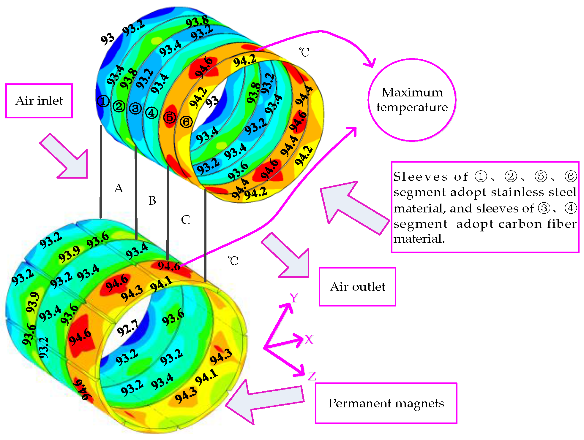
Table 4 gives the parameters of the material. Therefore, in this paper, the sleeves, which are coated on the outer surface of permanent magnet local maximum temperature, adopt carbon fiber material, and the other sleeves adopt stainless steel material. The proposed method (stainless steel and carbon fiber sleeves were used at the same model) integrates the inherent advantages of the two materials, so it can not only reduce the rotor eddy-current losses and decrease the temperature of permanent magnets, but also well fix the permanent magnets and protect them from being destroyed by the large centrifugal force.
By using the finite-element method, the electromagnetic field are calculated and the losses in different parts of PMSM are given in Table 5.
As shown in Table 5, when ①, ②, ⑤, ⑥ segment sleeves adopt stainless steel and ③, ④segment sleeves adopt carbon fiber material, the eddy-current losses in ③, ④ segment sleeves are obviously much lower than those in ①, ②, ⑤, ⑥ segment sleeves. The eddy-current losses in permanent magnets are decreased correspondingly, thus, the total rotor eddy-current losses can also be decreased. From a 3-D temperature field, the temperature distributions in different parts of PMSM can be obtained. As shown in Figure 5, the temperature of the stator winding decreases with the carbon fiber, but the reduction is not obvious. One point to take notice of is that the temperature distributions of the stator winding are the same compared with the prototype PMSM, namely, a similar “saddle” with high points at the two ends and low in the middle. The reason is that the two end windings conduct heat by air and the straight segment of the winding conducts heat via the stator silicon steel sheet, moreover, the thermal conductivity of the silicon steel sleeve is larger than that of air. In addition, cooling wind flows through from air inlet (close to the fan) to the air outlet, thus, the temperature in the one end winding which is closer to the fan is lower than that at the back end.
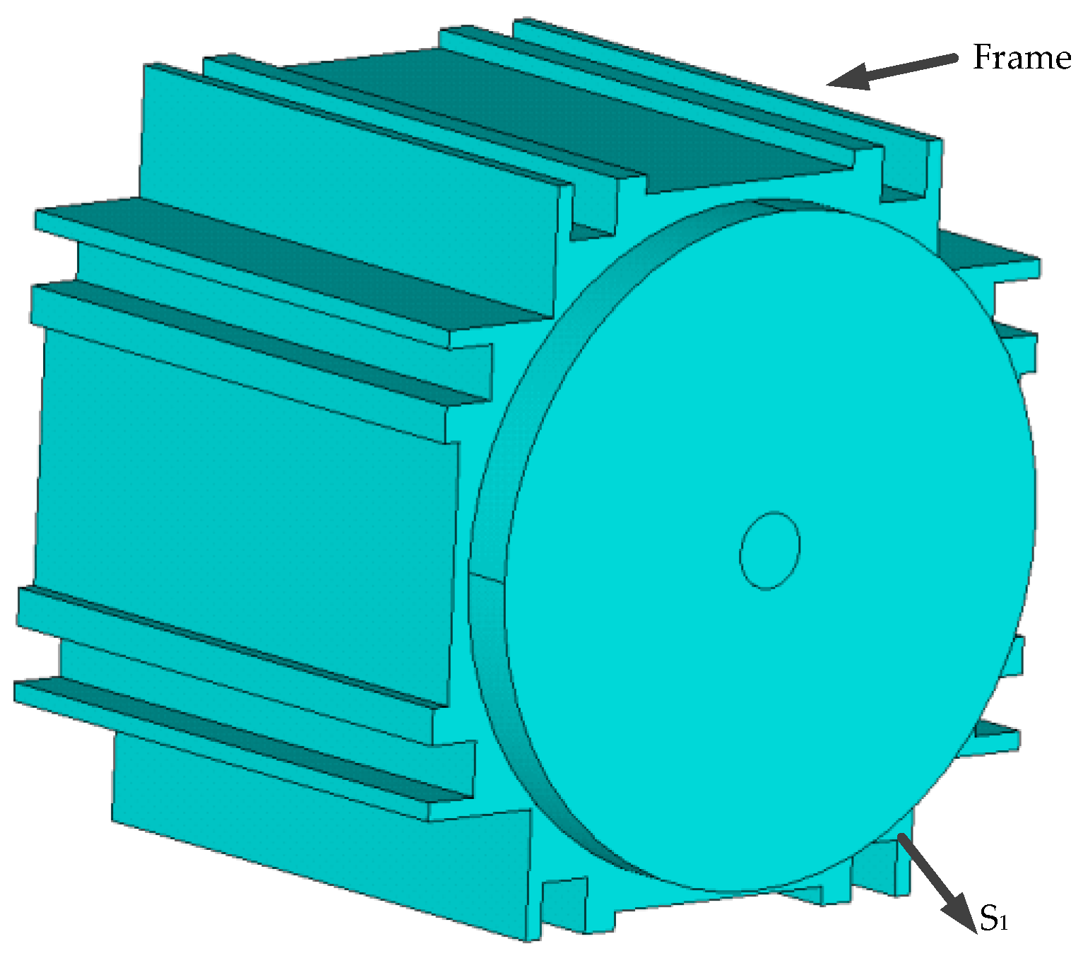
In the same way, after using carbon fiber, the temperature distribution of the frame can also decrease, but the reduction is not also obvious. The temperature distribution rule of the frame is low at the two ends and high in the middle, as shown in Figure 6. The reason is that the heat in the middle is mainly from the stator core and winding losses, meanwhile, because of the fan at the frame back-end, the temperature of the frame back-end is lower compared with the frame front-end. In addition, the heat dissipation effect of the frame with a bare radiator is better.
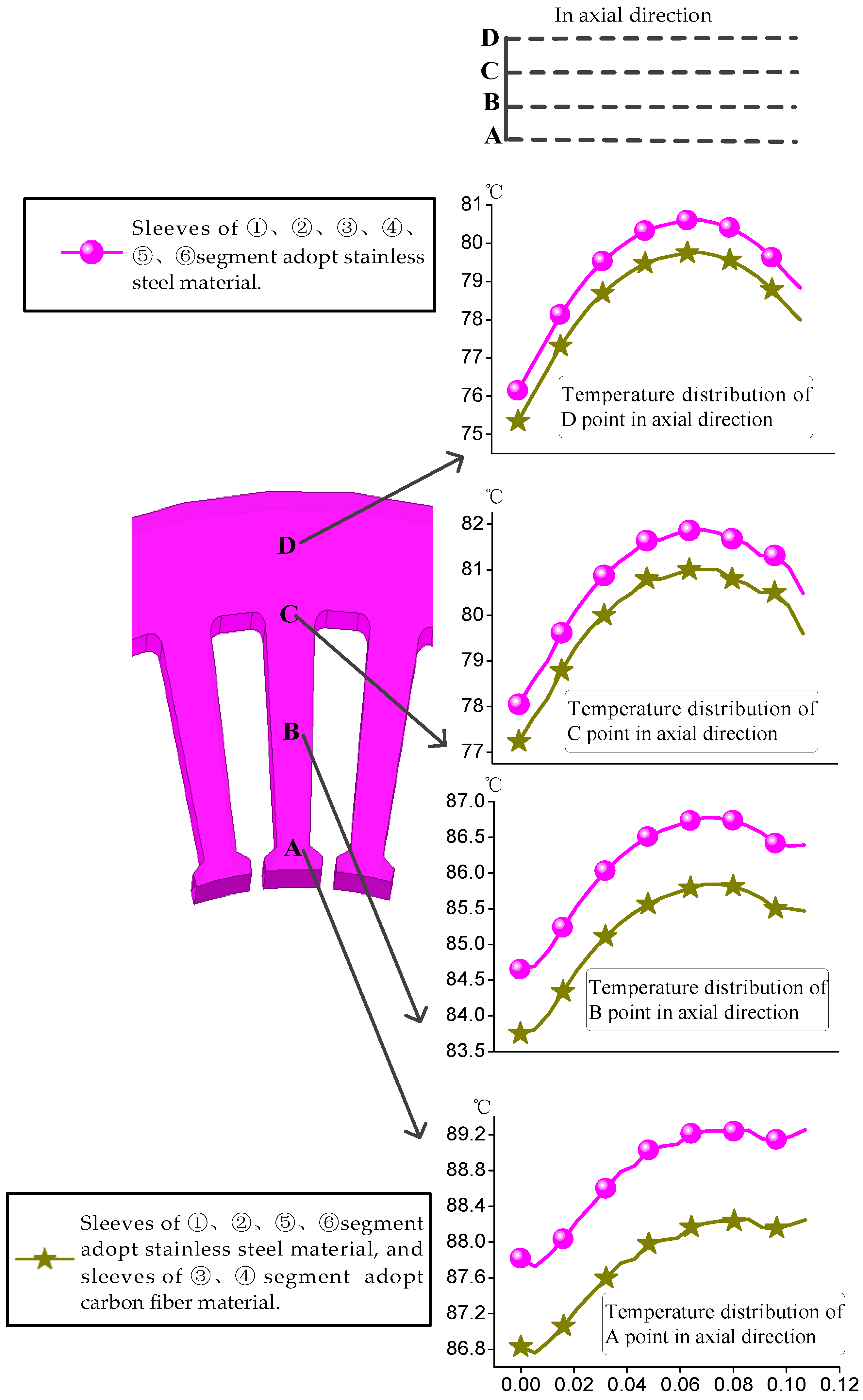
To study the temperature distribution of the stator core, uniformly taking A, B, C, D four points from tooth tip to yoke, when ①, ②, ⑤, ⑥ segment sleeves adopt stainless steel and ③, ④ segment sleeves adopt carbon fiber material, the temperatures of the tooth center line in the axial and radial direction both decrease, which is shown in Figure 7.
From Figure 7, it can also be found that the temperature from the stator tooth to the stator yoke gradually decreases in radius before and after the proposed method for suppressing the permanent magnet local maximum temperature is applied. The reason is that, A point is close to the air gap, resulting in difficulty in cooling the coil, and the stator yoke is close to the frame, so accordingly, the heat dissipation condition is better. In the axial direction, due to the eddy-current loss distribution and cooling effect, the temperature first increases and then decreases.
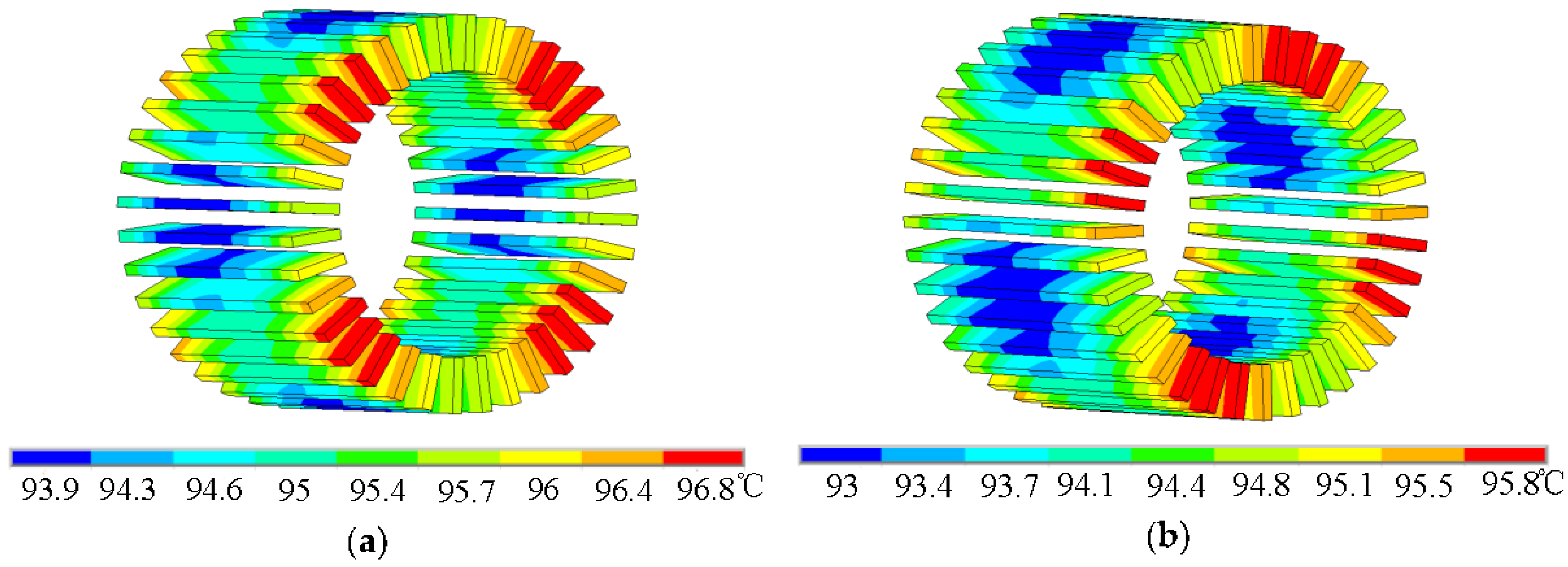
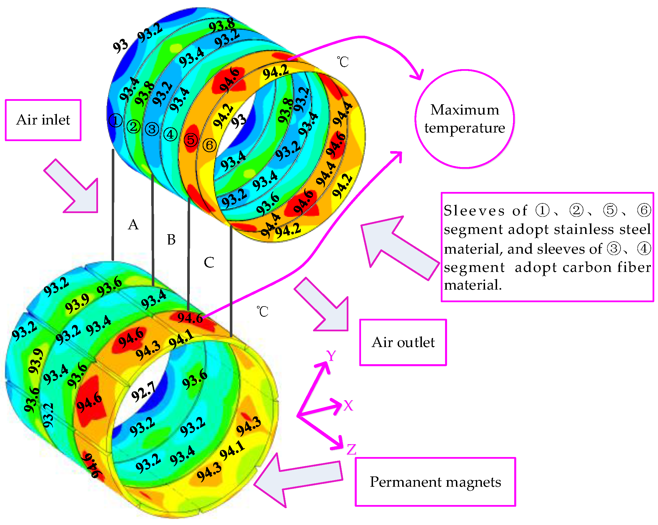
At the same time, this will have a significant effect on the rotor temperature, as shown in Figure 8. Firstly, the maximum temperature of the permanent magnets decreases by 4.4 °C compared with the temperature of the prototype PMSM, which is below the N33SH magnets’ limiting working temperature (150 °C), moreover, the effect on decreasing the rotor temperature is larger than that decreasing the stator temperature. Next, the maximum temperature zone of the permanent magnets is greatly reduced. In addition, the position of the maximum temperature shows a fluttering phenomenon, whereby the maximum temperature position changes from the B segment to the C segment of the permanent magnet. Compared with the maximum temperature position of the prototype PMSM, this fluttering value is 16.1 mm. This can be explained as follows: on the one hand, because the conductivity of carbon fiber is relatively low, the total rotor eddy-current losses decrease. On the other hand, because the end of PMSM is close to a fan, its temperature is lower than that of the end far away a fan, and because the thermal conductivity of stainless steel is much larger than that of carbon fiber and the distribution of sleeves material is uneven in the axial direction, it can cause a heat transfer in the axial direction. Thus, the position of the maximum temperature of the permanent magnet is finally close to the air outlet, and the maximum temperature zone is reduced.
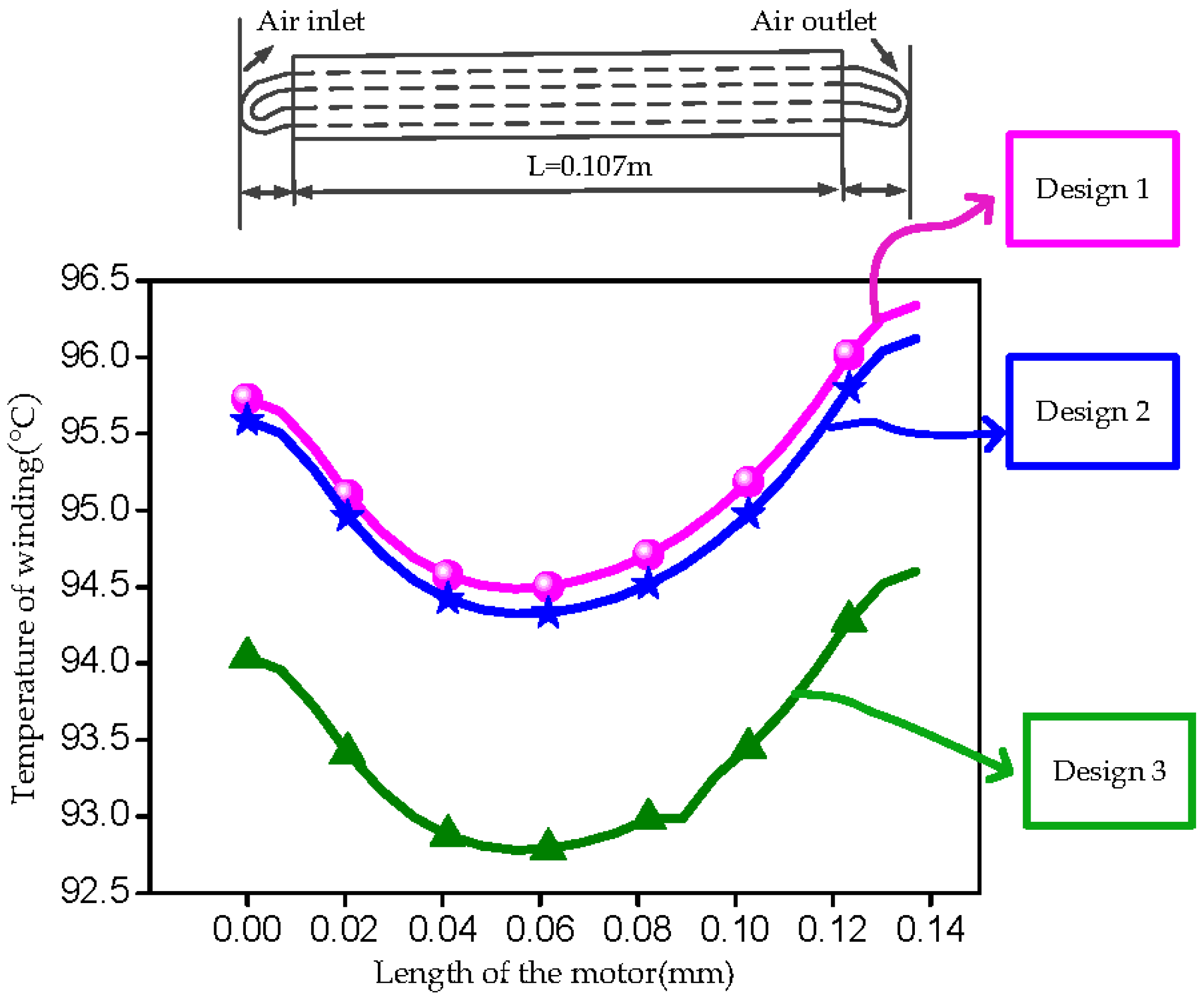
From the analysis results, it can be known that whether the motor power in different machines is large or small, the proposed method will have a relatively positive effect in decreasing the rotor eddy-current losses and the temperature of permanent magnets, which can suppress well permanent magnet demagnetization and protect the properties of permanent magnets. In order to find the variation law of the maximum temperature position and zone, in this paper, three rotor composite structures in the axial direction are presented, as follows:
Design 1:
③, ④, ⑤, ⑥ segment sleeves adopt stainless steel material, and ①, ② segment sleeves adopt carbon fiber material.
Design 2:
①, ②, ③, ④ segment sleeves adopt stainless steel material, and ⑤, ⑥ segment sleeves adopt carbon fiber material.
Design 3:
①, ②, ③, ④, ⑤, ⑥ segment sleeves adopt carbon fiber material.
By time stepped finite element analysis, the losses in different parts of the PMSM can be obtained under the three designs, as shown in Table 6, Table 7 and Table 8. From the loss calculation results, it can be seen that the eddy-current losses in the sleeve that adopted carbon fiber material are much lower than in those that adopted stainless steel, and the eddy-current losses in the sleeve that adopted carbon fiber material are almost 0 W, since the conductivity of carbon fiber is very low (1.5 × 10⁵ S/m). Simultaneously, the three designs can reduce the total rotor losses, with the reduction degree of Design 2 being slightly better than that of Design 1. The reduction of Design 3 is most obvious, compared with the eddy-current losses of the prototype PMSM, the eddy-current losses in the sleeve and permanent magnet decrease by 14.36 W, 3.53 W, respectively. In addition, when ①, ②, ⑤, ⑥ segment sleeves adopt stainless steel material and ③, ④ segment sleeves adopt carbon fiber material, the influence on reducing the eddy-current loss is the same as with Design 1 and Design 2.
By a 3-D steady thermal finite element model, the whole region 3-D heat flow density distribution in different parts of the PMSM operating at rated speed (2000 r/min) and rated load (R = 0.32 Ω and cos φ = 0.79) can be obtained under the three designs, which has an ambient temperature of 10 °C.
As shown in Figure 9, the three designs can decrease the temperature of the stator winding, Design 3 is the best compared with the prototype PMSM, and the maximum temperature of the stator winding decreases by 2.5 °C. In addition, Design 2 is better than Design 1. However, the temperature distribution rule of the stator winding is not changed under the three designs.
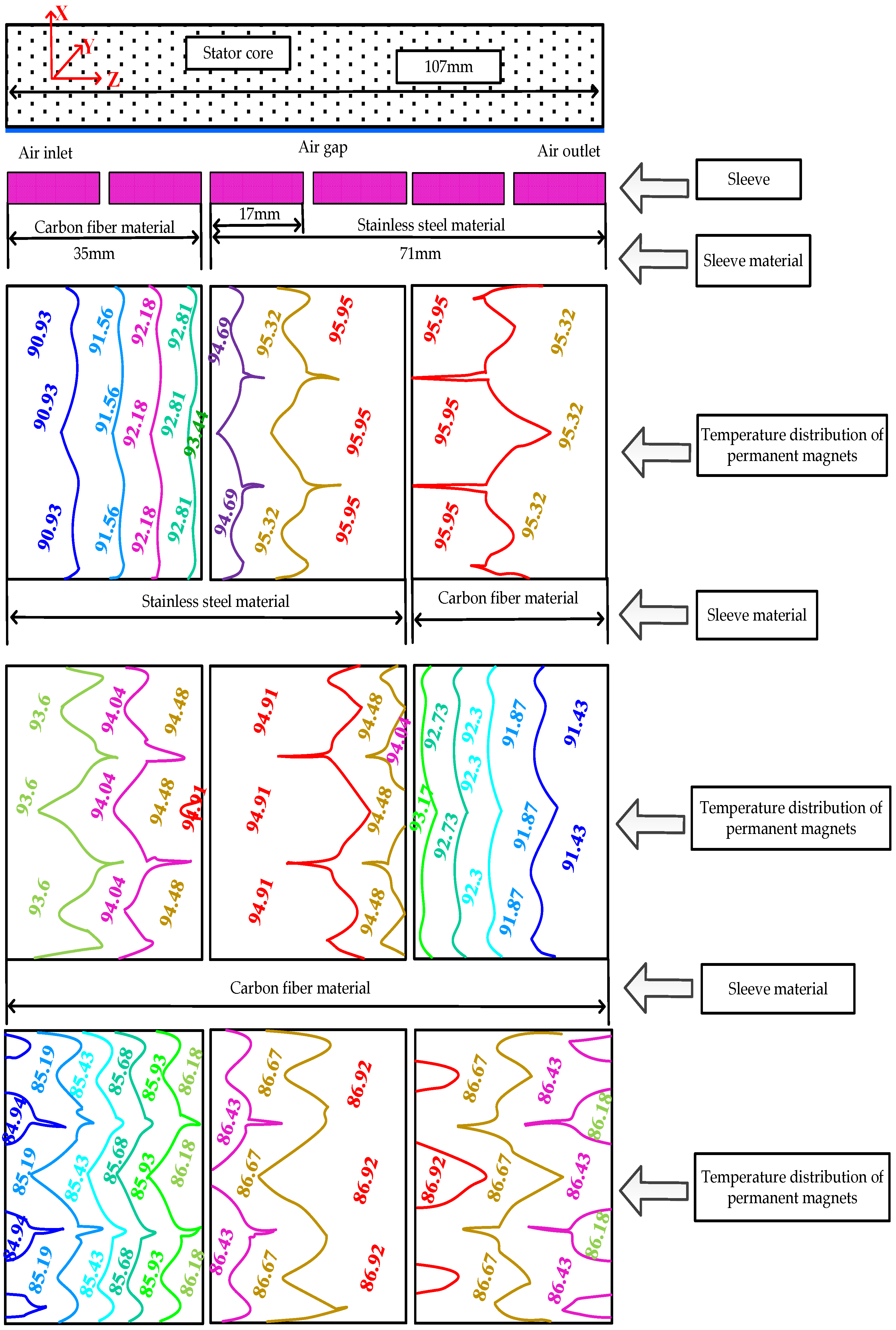
From 
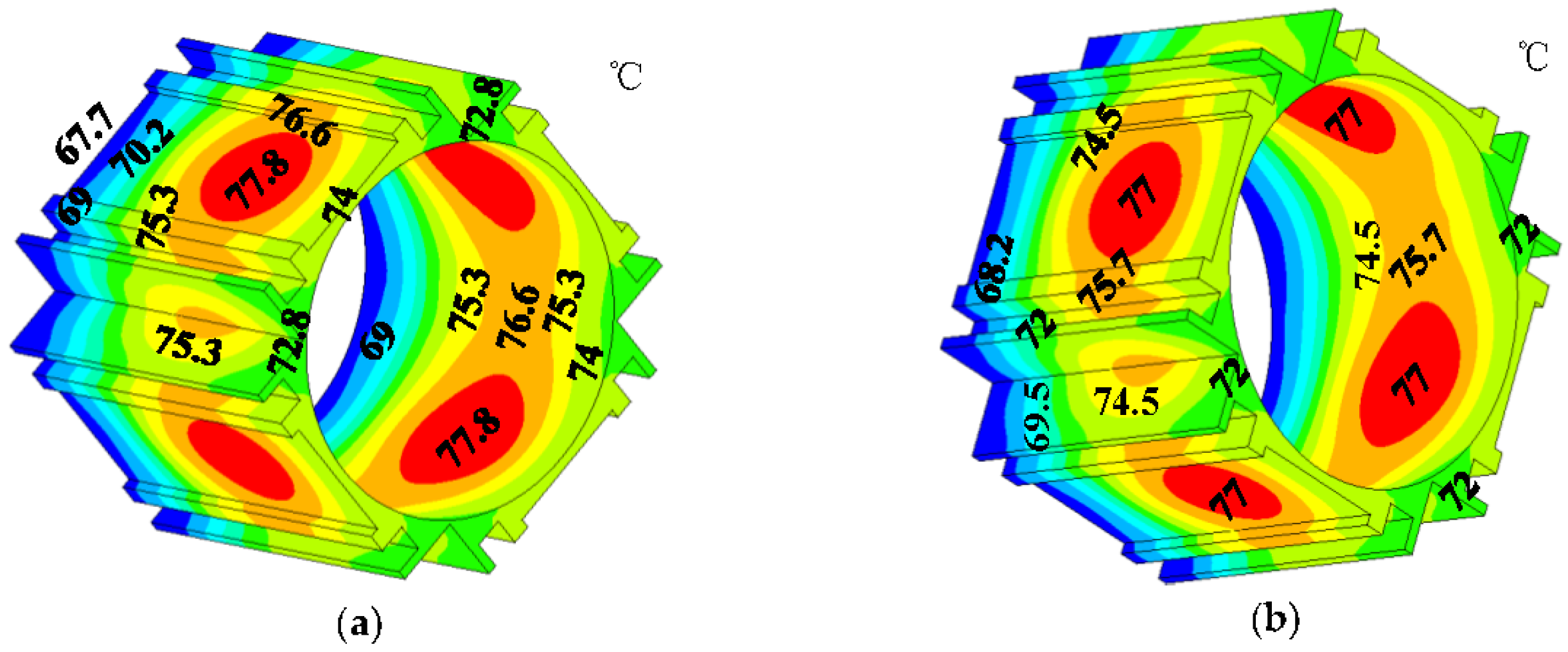
Figure 10, it can be known that the maximum temperature of the permanent magnets decreases by 3.05 °C under Design 1 compared with the temperature of the prototype PMSM. Moreover, the maximum temperature position is located on the permanent magnets which are coated on the inner surface of ④, ⑤ segment sleeves. However, the maximum temperature zone of the permanent magnets can increase. For Design 2, the maximum temperature position is located on the permanent magnets which are coated on the inner surface of ③, ④ segment sleeves, and the maximum temperature zone of the permanent magnets can increase. At the same time, the minimum temperature position is coated on the inner surface of ⑥ segment sleeve and decreases by 5.07 °C. This is because the conductivity of the carbon fiber is much lower and it can reduce the eddy current loss in the rotor, although the fan is close to segment sleeves ①, ②.
Design 1 and Design 2 can decrease the rotor temperature. However, their degree of decreasing is not better than with the strategy that ①, ②, ⑤, ⑥ segment sleeves adopt stainless steel and ③, ④ segment sleeves adopt carbon fiber. One point to be noticed is that, whether Design 1 or Design 2 is used, the maximum temperature zone can increase compared with the prototype PMSM. The reason is that the thermal conductivity of stainless steel (59 W/(m·K)) is much larger than that of carbon fiber (1.7 W/(m·K)), and because the distribution of sleeves material is uneven in the axial direction, it can cause a thermal transfer in the axial direction.
For Design 3, compared with the prototype PMSM, the maximum temperature of permanent magnets decreases by 12.08 °C, but the maximum temperature position and zone are not changed. The position is located on the permanent magnets which are coated on the inner surface of ④, ⑤segment sleeves. The reason is that sleeves adopt the same material, which cannot cause thermal transfer in the axial direction, and the fan only plays an air cooling effect. Therefore, it can be known that is all sleeves adopt the same material, the maximum temperature position and zone of the permanent magnets will not change.
From the above analysis, it can be known that the three designs can decrease rotor losses and temperature compared with the prototype PMSM. Thus, adopting a sleeve composition structure of carbon fiber and stainless steel could improve the cooling efficiency of the system. Simultaneously, compared with the method for suppressing permanent magnet local maximum temperature, the three designs revealed the change rule of the position and zone of the rotor maximum temperature. The obtained conclusions may provide useful references for the design and research of PMSMs.

4. Conclusions

In this paper, taking a 12.5 kW, 2000 r/min PMSM with stainless steel sleeve as an example, an by combining a time-stepping finite-element analysis method, the electromagnetic field and temperature field are comparatively analyzed based on different strategies and methods for suppressing permanent magnet demagnetization under a multi-physical field and rotor multi-topology structure. The following conclusions could be obtained:
(1)
The method that suppresses the permanent magnet local maximum temperature can not only reduce the rotor eddy-current loss, but also the temperature in different parts of a PMSM, and the zone of the maximum temperature of permanent magnets will also be reduced. In addition, the maximum temperature position of permanent magnets is close to the air outlet.
(2)
The temperature in different parts of the PMSM will decrease under Design 1 and Design 2, simultaneously, the maximum temperature position of permanent magnets will change, and the zone can increase. The maximum temperature position and zone are not changed under Design 3. From the viewpoint of preventing thermal demagnetization of permanent magnets, the strategy suppressing the local temperature peak of permanent magnets is best, followed by Design 3, and then Design 1 and Design 2.
(3)
Whether the power of the machine is big or small, the carbon fiber will have a relatively positive effect in decreasing the machine rotor temperature.

Acknowledgments

This work was supported by the National Natural Science Foundation of China under Grant 2015DFR70060.

Author Contributions

Lin Li implemented simulation; Weili Li supervised all process; Dong Li performed the experiments; Jinyang Li analyzed the data; Yu Fan checked paper format.

Conflicts of Interest

The authors declare no conflict of interest.

References

  1. Vidal, A.; Freijedo, F.D.; Yepes, A.G.; Fernandez-Comesana, P.; Malvar, J.; López, Ó.; Doval-Gandoy, J. Assessment and optimization of transient response of proportional-resonant current controllers for distributed power generation systems. IEEE Trans. Ind. Electron. 2013, 60, 1367–1383. [Google Scholar] [CrossRef]
  2. Krahenbuhl, D.; Zwyssig, C.; Kolar, J.W. Half-controlled boost rectifier for low-power high-speed permanent-magnet generators. IEEE Trans. Ind. Electron. 2011, 58, 5066–5075. [Google Scholar] [CrossRef]
  3. Cho, H.W.; Ko, K.J.; Choi, J.Y. Rotor natural frequency in high speed permanent magnet synchronous motor for turbo-compressor application. IEEE Trans. Magn. 2011, 47, 4258–4261. [Google Scholar] [CrossRef]
  4. Kolondzovski, Z.; Arkkio, A.; Larjola, J.; Sallinen, P. Power limits of high-speed permanent-magnet electrical machines for compressor applications. IEEE Trans. Energy Convers. 2011, 26, 73–82. [Google Scholar] [CrossRef]
  5. Jang, S.M.; Koo, M.M.; Park, Y.S.; Choi, J.Y.; Lee, S.H. Characteristic analysis of permanent magnet synchronous machines under different construction conditions of rotor magnetic circuits by using electromagnetic transfer relations. IEEE Trans. Magn. 2011, 47, 3665–3668. [Google Scholar] [CrossRef]
  6. Xing, J.; Wang, F.; Wang, T.; Zhang, Y. Study on anti-demagnetization of magnet for high speed permanent magnet synchronous machines. IEEE Trans. Appl. Supercond. 2010, 20, 856–860. [Google Scholar] [CrossRef]
  7. Guo, Y.; Zhu, J.; Wu, W. Thermal analysis of soft magnetic composite motors using a hybrid model with distributed heart sources. IEEE Trans. Magn. 2005, 41, 2124–2128. [Google Scholar] [CrossRef]
  8. Kolondzovski, Z.; Sallinen, P.; Arkkio, A. Thermal analysis of a high-speed PM machine using numerical method. In Proceedings of the International Conference on Electrical Machines, Italy, Rome, 6–8 September 2010; pp. 1–6. [Google Scholar]
  9. Bettayeb, A.; Jannot, X.; Vannier, J.C. Analytical calculation of rotor magnet eddy-current losses for high speed IPMSM. In Proceedings of the International Conference on Electrical Machines, Italy, Rome, 6–8 September 2010; pp. 1–6. [Google Scholar]
  10. Binder, A. Analytical calculation of eddy-current losses in massive rotor parts of high speed permanent magnet machines. In Proceedings of the International Conference on Symposium on Power Electronics, Electrical Drives, Automation and Motion, Ischia, Italy, 13–16 June 2000; pp. C2-1–C2-6. [Google Scholar]
  11. Aglen, O. Loss calculation and thermal analysis of a high-speed generator. In Proceedings of the International Conference on Electric Machines and Drives, Madison, WI, USA, 1–4 June 2003; pp. 1117–1123. [Google Scholar]
  12. Kirtley, J.L.; Lovelace, E.C. Drag loss in retaining rings of permanent magnet motors. In Proceedings of the International Conference on Electric Machines and Drives, Madison, WI, USA, 1–4 June 2003; pp. 1068–1072. [Google Scholar]
  13. Zhu, Z.Q.; Ng, K.; Schofield, N.; Howe, D. Improved analytical modeling of rotor eddy current loss in brushless machines equipped with surface mounted permanent magnets. IEE Proc. Electr. Power Appl. 2004, 151, 641–650. [Google Scholar] [CrossRef]
  14. VanderVeen, J.L.F.; Offringa, L.J.J.; Vandenput, A.J.A. Minimizing rotor losses in high speed high power permanent magnet synchronous generator with rectifier load. IEE Proc. Electr. Power Appl. 1997, 144, 331–337. [Google Scholar] [CrossRef]
  15. Li, W.L.; Qiu, F.B.; Zhang, X.C.; Yi, R. Influence of copper plating on electromagnetic and temperature fields in a high-speed permanent-magnet generator. IEEE Trans. Magn. 2012, 48, 2247–2253. [Google Scholar] [CrossRef]
  16. Li, W.L.; Qiu, F.B.; Zhang, X.C.; Cao, J.C.; Yi, R. Analyses on electromagnetic and temperature fields of superhigh-speed permanent-magnet generator with different sleeve materials. IEEE Trans. Ind. Electron. 2014, 61, 3056–3063. [Google Scholar] [CrossRef]
  17. Chunting, M.; Gordon, R.S.; Richard, B. Modeling of iron losses of permanent-magnet synchronous motors. IEEE Trans. Ind. Appl. 2003, 39, 734–742. [Google Scholar] [CrossRef]
  18. Li, W.L.; Ding, S.Y.; Zhou, F. Diagnostic numerical simulation of large hydro generator with insulation aging. IEEE Trans. Heat Transf. Eng. 2008, 29, 902–909. [Google Scholar] [CrossRef]
  19. Li, W.L.; Qiu, F.B.; Yi, R.; Zhang, X.C. Three-dimensional and analysis of axial–radial electromagnetic field calculation flux-type high-temperature superconducting synchronous motor. IEEE Trans. Appl. Supercond. 2013, 23, 3056–3063. [Google Scholar] [CrossRef]
  20. Li, W.L.; Cao, J.C.; Zhang, X.C. Electro-thermal analysis of induction motor with compound cage rotor used for PHEV. IEEE Trans. Ind. Electron. 2010, 57, 660–668. [Google Scholar] [CrossRef]
Figure 1. The experimental platform, results of calculation and experiment results, and rotor actual structure. (a) The experimental system; (b) The thermistor position in the winding; (c) Experiment results of phase current and voltage; (d) Rotor actual structure.
Energies 11 00040 g001
Figure 2. 3-D electromagnetic field calculation model.
Energies 11 00040 g002
Figure 3. 3-D temperature field analysis model of the PMSM.
Energies 11 00040 g003
Figure 4. Temperature distribution of permanent magnets and sleeves for the prototype PMSM.
Energies 11 00040 g004
Figure 5. Temperature distribution of the stator winding before and after the proposed permanent magnet local maximum temperature suppressing method is applied: (a) Temperature distribution of the stator winding before the proposed permanent magnet local maximum temperature suppressing method is applied; (b) Temperature distribution of the stator winding after the proposed permanent magnet local maximum temperature suppressing method is applied.
Energies 11 00040 g005
Figure 6. Temperature distribution of frame before and after the applying the proposed permanent magnet local maximum temperature suppressing method: (a) Temperature distribution of frame before the applying the proposed permanent magnet local maximum temperature suppressing method; (b)Temperature distribution of frame after the applying the proposed permanent magnet local maximum temperature suppressing method.
Energies 11 00040 g006
Figure 7. Temperature distribution of tooth center line in axial direction before and after the proposed method suppressing permanent magnet local maximum temperature.
Energies 11 00040 g007
Figure 8. Temperature distribution of the permanent magnet and sleeve after applying the proposed permanent magnet local maximum temperature suppressing method.
Energies 11 00040 g008
Figure 9. Temperature distribution of stator winding under three designs.
Energies 11 00040 g009
Figure 10. Temperature distribution of permanent magnets under three designs.
Energies 11 00040 g010
Table 1. Parameters of the permanent magnet synchronous motor (PMSM).
ItemsValue
Rated power12.5 kW
Rated voltage364 V
Rated current26.2 A
Rated torque60 N·m
Rated speed2000 r/min
Pole pairs4
Frequency133.33 Hz
Inertia0.008 kg·m2
Inductance0.0053 H
End leakage inductance0.00022 H
Resistance0.32 Ω
Stator outer diameter180 mm
Stator inner diameter103 mm
Stator core length107 mm
Sleeve thickness0.2 mm
Permanent magnet thickness3 mm
Rotor typePM
Table 2. Comparison of calculated results and test data.
Symbol (Units)Test DataCalculated Data
Stator windings loss (W)642.4614.49
Stator core loss (W)120.3126.8
Magnets loss (W)18.720.57
Sleeves loss (W) 32.231.16
Phase voltage (V)210212.3
Phase current (A)26.225.3
Table 3. The maximum temperature comparison of calculated results and test data (°C).
Maximum TemperatureTest DataCalculated Data
Stator windings9996.8
Frame7777.8
Permanent magnets103.799
Table 4. Material characteristics of carbon fiber.
SymbolValue
Conductivity (S/M)1.5 × 105
Relative permeability1
Thermal conductivity (W/(m·K))1.7
Table 5. Losses in different parts of PMSM (W).
Sleeve MaterialStainless SteelCarbon FiberStainless Steel
Sleeve number
Sleeve losses 4.584.671.231.224.214.22
Sleeve total losses 20.13
Magnets losses 6.324.76.13
Magnets total losses17.15
Copper loss 614.49
Stator core loss126.8
Table 6. Losses in different parts of PMSM under Design 1 (W).
Sleeve MaterialCarbon FiberStainless SteelStainless Steel
Sleeve number
Sleeve losses 0.960.955.065.214.164.17
Sleeve total losses20.51
Magnets losses 4.487.816.07
Magnets total losses18.36
Copper loss 614.49
Stator core loss126.8
Table 7. Losses in different parts of PMSM under Design 2 (W).
Sleeve MaterialStainless SteelStainless SteelCarbon Fiber
Sleeve number
Sleeve losses 4.594.674.44.520.860.86
Sleeve total losses19.9
Magnets losses 6.316.554.22
Magnets total losses17.08
Copper loss 614.49
Stator core loss126.8
Table 8. Losses in different parts of PMSM under Design 3 (W).
Sleeve MaterialCarbon FiberCarbon FiberCarbon Fiber
Sleeve number
Sleeve losses 0.950.971.110.880.87
Sleeve total losses5.77
Magnets losses 4.594.74.33
Magnets total losses13.62
Copper loss 614.49
Stator core loss 126.8

