Development and Analysis of a Novel Spherical 2-Degree-of-Freedom (2-DOF) Hybrid Stepping Motor

College of Electrical Engineering, Shandong University, Jinan 250061, China
*
Author to whom correspondence should be addressed.
Energies 2018, 11(1), 41; https://doi.org/10.3390/en11010041
Submission received: 17 November 2017
/
Revised: 15 December 2017
/
Accepted: 21 December 2017
/
Published: 25 December 2017
(This article belongs to the Section I: Energy Fundamentals and Conversion)
Abstract
:A novel spherical two-degree-of-freedom (2-DOF) hybrid stepping motor is proposed in this paper, which has a simple and compact mechanical structure and is easy to manufacture, assemble, control and apply. The motor is composed of two sub-motors, each of which is a hybrid stepping type with an arc-shaped stator and a specially designed bearing structure. The rotational axes of these two sub-motors cross at the sphere center, and this structure enables the 2-DOF motor to move in any direction. Due to the mutual influence of permanent magnet (PM) leakage flux between the two sub-motors, the 3-D magnetic field distribution inside the motor becomes more complex, and thus the 2-D equivalent magnetic field analysis method is proposed, with two types of 2-D equivalent motor models established. The accurate one can take into account of the PM leakage flux influence yet is only suitable for solving motor’s static and steady state problem, whilst the simplified one can solve all the problems and is applicable for the more typical situation where the PM leakage flux influence can be almost neglected via optimal structure design. A prototype of the proposed spherical 2-DOF motor with outside diameter of 50 mm is newly manufactured and experimented to validate the feasibility of motor’s operational principle, and the accuracy of both 2-D equivalent motor models is verified by the 3-D finite element analysis (3-D FEA) calculation results. Based on the 2-D equivalent motor models, the 2-D FEA is employed for the performance analysis, such as no-load back electromotive force (EMF), tooth-layer permeance harmonics, detent torque, pull-out torque, unbalanced force, etc., which is characterized by time- saving, high accuracy and good versatility.
1. Introduction
The requirements for motion on a spherical surface are increasing in many fields. For example, the motion of robot’s eyes, automated astronomical telescopes, artificial limb-joints such as wrists, satellite-tracking antennas, etc., are basically in a shape of spherical surface. Traditionally, the moving actuator is composed of several motors. To accomplish this complicated spherical surface motion, two or three sets of rotary motors are needed, but this results in a complex structure, large size, heavy devices, difficult maintenance and therefore low efficiency. In addition, it is difficult to control multi-motors independently and synchronously with high precision by using only one set of control devices. To effectively realize spherical surface motions, great attention has been paid to the motors with multiple degrees-of-freedom (DOFs), which can greatly simplify the mechanical structure and improve the precision and response speed.
A number of notable works have been done for the development and investigation of multi- DOF motors. For example, Williams et al. [1] developed the first spherical induction motor in order to obtain a variable-speed drive regarding to a single-axis ac motor. Davey et al. [2] have derived the torque model of this kind of induction motor through an integration of Maxwell stress moment over the rotor surface. Lee and Kwan [3] have developed a 3-DOF spherical stepper motor based on the variable reluctance principle, which simplifies the mechanical structure and improves the servo characteristics of the spherical induction motor, and which takes advantages of the high magnetic property of the rare-earth permanent magnets (PMs). Several variations of spherical motors with structures similar to [3] have been investigated. Wang et al. [4,5,6] developed spherical actuators that can achieve 3-DOF motion. The torque models, optimal design procedures and control strategies of these spherical actuators were proposed and confirmed by experimental measurements. Chirikjian and Stein [7] have proposed a spherical stepper motor with electromagnet-pole stator and PM-pole rotor. Difference in symmetric layout of stator and rotor poles allows the 3-DOF stepping motion. Kahlen et al. [8] have developed a spherical motor, which consists of an inner rotor mounted with 112 PM poles and a stator with 96 individually controlled windings. The torque produced by the interaction of stator windings and rotor PMs was calculated numerically. Yan et al. [9] presented the torque model of a ball-joint-like 3-DOF PM spherical motor, which consists of a spherical rotor with multiple fan-shaped PM poles and a spherical-shell-like stator with multi-layer air-core coils. In addition, Toyama et al. [10] and Maeno et al. [11] proposed different types of ultrasonic spherical actuators. Shi et al. [12] and Yano et al. [13] developed 2-DOF small-sized spherical stepping motors, which consist of arc-shaped variable-reluctance stepping motors or hybrid stepping motors, controlled precisely by a micro-stepping current in open-loop operation.
Due to the complexity in structure, design and analysis, the difficulty in manufacturing and control, most of the proposed multi-DOF motors are still in the laboratory research stage. Among them the 2-DOF spherical stepping motors [12,13] are well-suited for low toque, high positioning resolution applications, due to their superior features of compact structure, small volume, no cumulative error and easy open-loop control. Nevertheless, due to the stator-end-cover configuration and the small desired air-gap length, the mechanical structure of these 2-DOF spherical stepping motors is generally complicated, which increases the volume, manufacturing difficulty, costs and decreases the force-energy index as well as positional holding accuracy. As a result, the development and practical application of these types of motor is subject to several limitations.
In order to simplify the mechanical structure and manufacturing process, reduce the volume and weight, improve the force-energy index and promote the practical application, a novel spherical 2-DOF hybrid stepping motor is proposed in this paper. It is difficult to analyze the 2-DOF motor by using approaches applicable to normal hybrid stepping motors [14,15,16,17,18,19,20], due to the complex electromagnetic coupling relationships inside the motor. Although the 3-D finite element analysis (FEA) approach can deal with complex magnetic field problems, it is quite time-consuming for a motor’s initial design and performance analysis, especially when simultaneously taking into account two sub-motors, and therefore a 2-D equivalent magnetic field analysis method is proposed in this paper. This paper will be organized as follows: in Section 2, structure and operational principle of the 2-DOF motor are introduced. In Section 3, two forms of 2-D equivalent motor model are established via structural transformation from the 3-D motor model, based on which, the 2-D FEA can be used for solving motor’s static and steady state and transient problem. In Section 4, both the feasibility of motor’s operational principle and accuracy of the established 2-D equivalent motor model are verified by experimental and 3-D FEA results. In Section 5, the 2-D FEA is employed for motor’s performance analysis, such as tooth-layer permeance harmonics, detent torque, holding torque and torque-angle property, pull-out torque, unbalanced force, and is compared with the analytical method, which has distinct advantage of high accuracy when considering the saturation effects.
2. Description of the Spherical 2-DOF Hybrid Stepping Motor
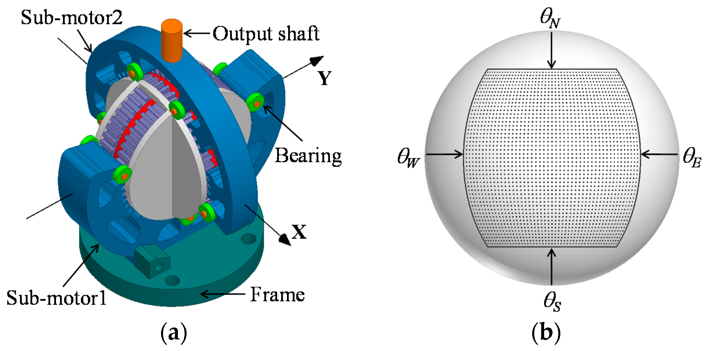
The configuration of the developed spherical 2-DOF hybrid stepping motor is shown in Figure 1a. It can be seen that the motor is composed of four parts, i.e., sub-motor1, sub-motor2, the output shaft and the frame. Two sub-motors are both inner-rotor type hybrid stepping motors (HSMs) with identical stator and rotor diameter, assembled together orthogonally. The motor’s operational principle to realize the 2-DOF motion is as follows: the stator of sub-motor1 is fixed on the frame, whilst the rotor can drive sub-motor2 as well as the output shaft to rotate around the X-axis (which is spatially stationary) when the stator windings are energized. At the same time, the stator of sub-motor2 can drive the output shaft to rotate around the Y-axis (which rotates synchronously with two rotors) when the stator windings are energized. As a result, the output shaft can realize the 2-DOF motion on a spherical surface, since the X-axis and Y-axis are orthogonally crossed at the motor’s sphere center. The 2-DOF motion trajectory is schematically illustrated in Figure 1b, where the tracking points are limited to the spherical region surrounded by north latitude θN, south latitude θS, east longitude θE, west longitude θN, and the positioning resolution is proportional to the points density, which can be generally improved by decreasing the tooth pitch and using the micro-stepping driving method [21]. Load devices such as a charge coupled device (CCD) camera can be mounted on the output shaft to realize the positioning in any direction.
Figure 2 shows the structure decomposition diagram of the 2-DOF motor. It can be seen that both sub-motors have arc-shaped stators with an arc angle slightly bigger than 180°. The two rotors are reversely connected with each other via the non-magnetic end covers, and all the rotor cores have the same outside diameter as the end cover. The small bearings are symmetrically mounted on both sides of the stator cores via the support shafts, which can slide around the surface of the end cover and enable the rotor to rotate smoothly around the stator (sub-motor1) or the opposite (sub-motor2). Generally, both sub-motors are designed into small length-diameter ratio to obtain a relatively large operation range, e.g., ≥±45° in this case. Moreover, the stator and rotor can be made up of solid iron core, laminated silicon steel sheet, or soft magnetic composite material (SMC).
The energy stored in the magnetic field of each sub-motor can be expressed as:
where Wpm is the energy stored in PM, Ww is the energy stored in winding at I, I = [ia, ib, …, im]T is the phase currents matrix, L = [Lxy] (x = a, b, …, m; y = a, b, …, m) is the phase inductances matrix. By using coenergy method, the total torque T can be derived as [22]:
where ψ = LI + ψpm is the total flux matrix, ψpm = [ψpma, ψpmb, …, ψpmm]T is the PM flux matrix, tpr is the rotor tooth pitch (mechanical angle), Tpm is the PM torque caused by the interaction effect between phase currents and PM fluxes, Tr is the reluctance torque caused by the phase inductances variation, and Tcog is the cogging (detent) torque caused by the variation of stored PM energy as a function of rotor position. Accordingly, Tpm can be determined when motor’s m phases are energized with ideal sinusoidal currents as:
where Im is the current amplitude, δ is defined as the torque angle, ψmax and ψmin are the maximum and minimum value of the PM flux.
Compared to most spherical multi-DOF motors, the developed spherical 2-DOF hybrid stepping motor has the following advantages: each sub-motor can be separately fabricated and the two sub-motors can be directly connected via the rotor end cover, which simplifies the assembly; stator end covers are omitted since the rotors are directly supported by the small bearings, which simplifies and makes the motor structure compact and convenient for the stator winding placement; positioning resolution may be easily improved by synchronously decreasing the rotor tooth pitch of each sub-motor to the same value, due to the fact the two sub-motors have the same rotor outer diameter and thus the same rotor tooth pitch. However, compared with normal HSM, mechanical robustness of each sub-motor might be reduced and frictional resistance may be higher due to the specially designed bearing structure, which should be improved via the optimal design of the bearing structure.
3. 2-D Equivalent Magnetic Field Analysis
3.1. 3-D Equivalent Motor Model
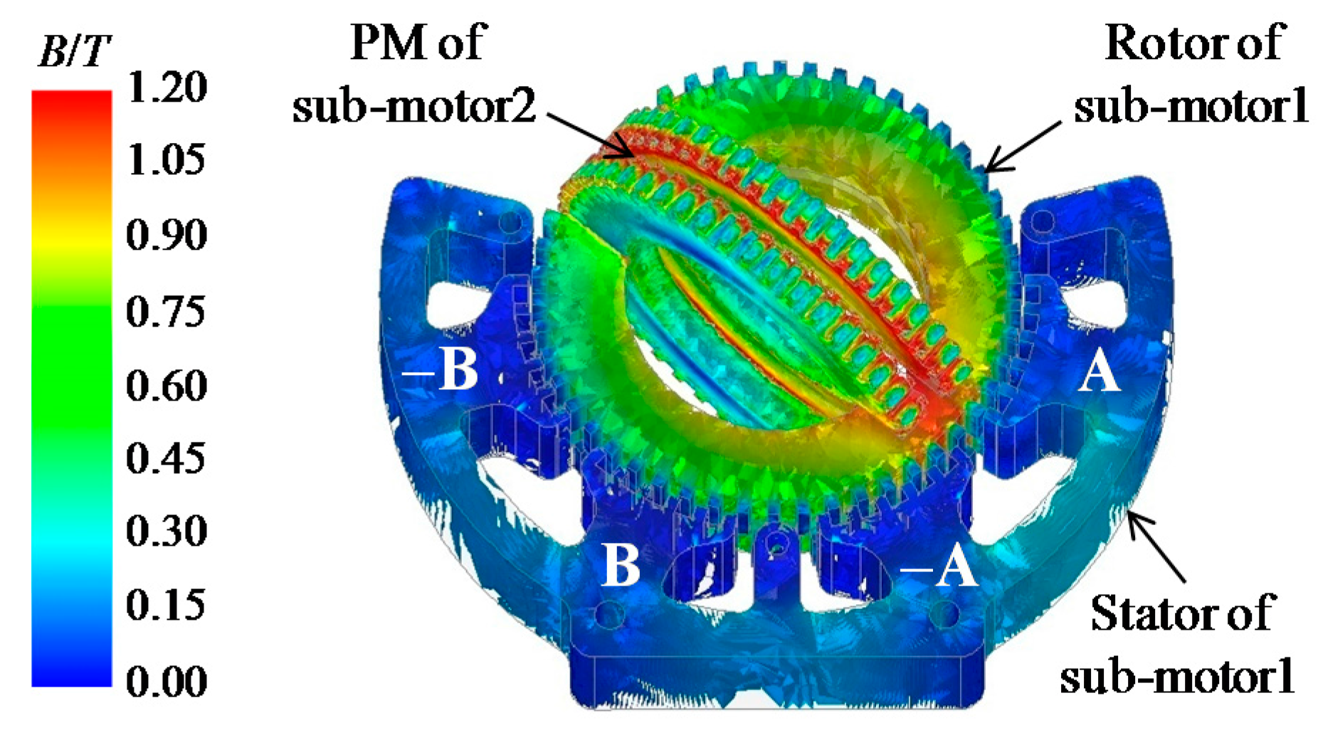
Since the PMs and rotor cores of the two sub-motors are designed as an open-ring structure and mutually orthogonal, the PM leakage flux produced at the PM opening place of one sub-motor will form a closed magnetic circuit via the stator and rotor core of the other one and influence its magnetic field distribution. e.g., setting the PM of sub-motor1 as vacuum, the magnetic field produced by the PM of sub-motor2 is calculated by 3-D FEA, as shown in Figure 3. It can be seen that the PM leakage flux mainly forms closed magnetic circuit via the rotor core of sub-motor1 and influences its rotor magnetic field distribution.
Taking sub-motor1 for instance, its 3-D equivalent motor model considering the influence of PM leakage flux of sub-motor2 is shown in Figure 4, where the PM of sub-motor2 is equivalently modeled by two fan-shaped rotor PMs magnetized in the radial direction, and the auxiliary rotor can provide a magnetic circuit for the PM flux. The rotor polarities N, S are produced by the PM of sub-motor1, and N′, S′ by the equivalent PMs of sub-motor2.The N-pole rotor and S-pole rotor are staggered by one-half the rotor tooth pitch. θ is the operation angle, and θ = 0 represents the position where the stator symmetrical line (baseline) is aligned with the rotor one. α, β represent the rotor’s relative position with respect to the centerline of pole A and pole B, respectively.
3.2. Acurate 2-D Equivalent Motor Model
To simplify the 3-D magnetic field analysis, save computing time and obtain high calculation accuracy, the accurate 2-D equivalent motor model as well as 2-D equivalent magnetic field analysis method is proposed. Neglecting the electromagnetic influence of the stator poles where the small bearings are placed, the accurate 2-D equivalent motor model corresponding to part II–V in Figure 4 can be established, as shown in Figure 5a–d, respectively. Taking part I for instance, its 2-D equivalent model as shown in Figure 5a is characterized by:
- The rotor polarities N, S are equivalently produced by the two stator PMs symmetrically placed in the stator yoke and inversely magnetized.
- The two rotor PMs have the same polarities and relative position with respect to stator pole A (as illustrated by angle α) as those of part I.
- The right half of the model is exactly the same as part I, which has opposite rotor polarity and inverse winding direction (to the two stator poles separated by 180°) to the left half, thus the electromagnetic properties of the two half models are equal according to Equation (2).
- The stator and rotor core length is one half the rotor core length of part I.
For an accurate 2-D equivalent motor model, it should be specially pointed out that:
- The influence of mutual inductance is small enough to be neglected.
- The sum of calculation results of all the 2-D models corresponding to each part can be directly applied to the actual motor, without any post-processing.
- It is suitable for solving motor’s static and steady state problem and analyzing the influence of PM leakage flux between two sub-motors, whereas unable for the transient problem, because of each model is the single-phase motor and cannot realize the two-phase operation.
3.3. Simplified 2-D Equivalent Motor Model
To further simplify the 2-D equivalent magnetic field analysis, realize the two-phase operation and solve the transient problem, a simplified 2-D equivalent motor model is proposed. Supposing that the mutual influence of PM leakage flux between the two sub-motors can be almost neglected after structural optimization, the two sub-motors can be analyzed independently. In this case, part I as shown in Figure 4b is equal to part III (I = III) in operational principle according to Equation (2), so for II = IV. Furthermore, supposing that the rotor in Figure 4c rotates one-half a rotor tooth pitch and all the windings are inversely supplied, Figure 6a can be obtained. As can be seen, Figure 6a is exactly equivalent to Figure 4c, namely, III = V, IV = VI. Since Figure 4b has the same rotor position and opposite rotor polarity as Figure 6a, one part of each, for example, part I and part VI, can be selected and assembled together in order to constitute a novel structured motor, in which the rotor polarity can be produced by the stator PMs, as shown in Figure 6b. As a result, the simplified 2-D equivalent motor model is obtained. In fact, the mutual influence of PM leakage flux between two sub-motors will inevitably lead to the performance reduction (which will be analyzed in later Chapters), which should be weakened in most of the expected situations, and thus the simplified 2-D equivalent motor model will be more universally used for the 2-D equivalent magnetic field analysis of the 2-DOF motor.
PM parameters of both the accurate and simplified 2-D equivalent motor model can be determined as follows: Taking sub-motor1 for instance, firstly, its 3-D motor model is built, and the magnetic field distribution produced by the PM of sub-motor2 is obtained by 3-D FEA (see Figure 3), then the rotor PM parameters of its accurate 2-D model can be determined by making the rotor saturation level equal to its 3-D model; Secondly, the air-gap flux density distribution produced by the PM of itself is obtained by 3-D FEA, then the stator PM parameters of both 2-D models can be determined by making the air-gap PM flux density equal to its 3-D model. Obviously, the motor’s end effect can be considered in this PM parameter determination.
4. FEA and Experimental Verification
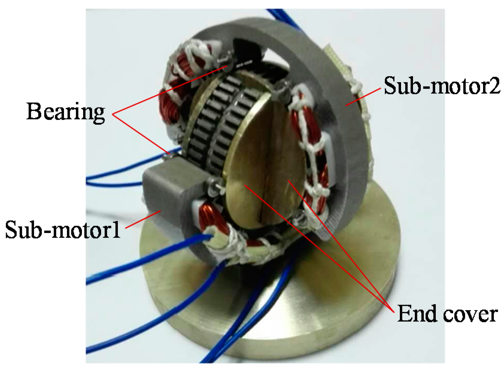
A prototype of the developed spherical 2-DOF hybrid stepping motor is newly fabricated as shown in Figure 7, with the design parameters listed in Table 1 and Table 2.
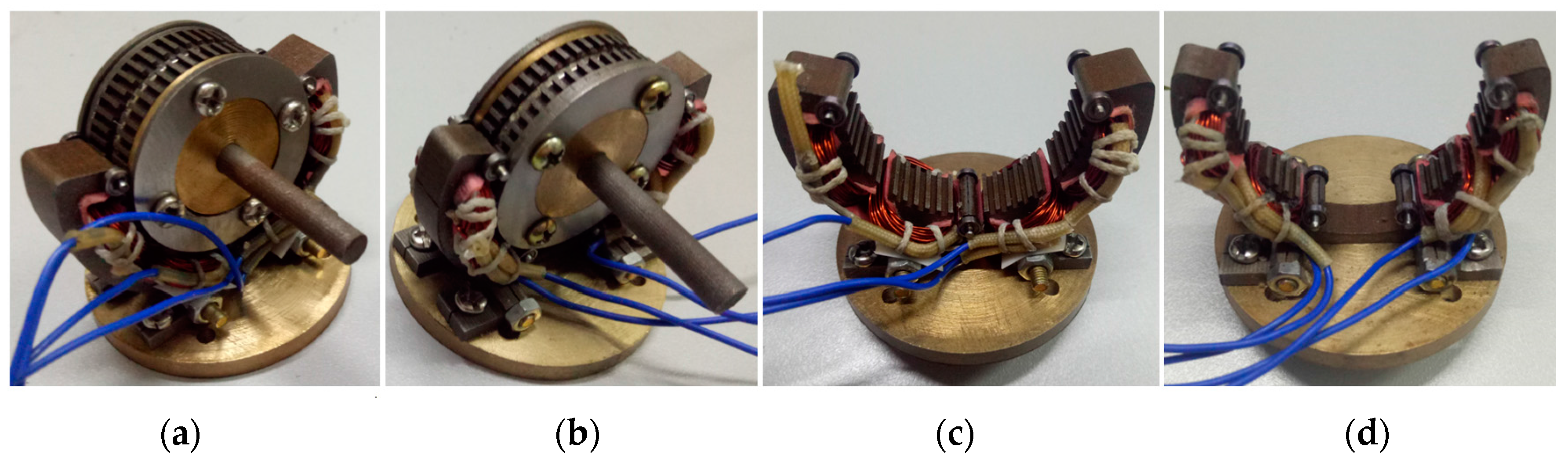
To verify the actual operational feasibility and the theoretical analysis of the 2-DOF motor, test motors corresponding to each sub-motor were designed and fabricated for the experimental test, neglecting the mutual influence of PM leakage flux between two sub-motors, as shown in Figure 8. Each testing motor has the same design parameters as the primary sub-motor, except that the rotor core and the PM are kept complete to realize the normal rotation, and the output shaft is adopted for the convenience of experimental study.
4.1. 3-D FEA Verification of the 2-D Equivalent Motor Model
Based on Table 1 and Table 2, one step of no-load calculation in terms of the spherical 2-DOF motor (taking into account of the mutual influence of PM leakage flux), sub-motor1, sub-motor2 is carried out, respectively, by using 3-D FEA, with the results shown in Figure 3 and Figure 9. It can be seen that the motor’s end effect can be effectively taken into consideration by adding the end-effect solution region (the solution region outside the stator is not illustrated in the figure). Accordingly, the following parameters can be determined: The maximum rotor flux density produced by the PM leakage flux is about 1.1 T (sub-motor1), 1.3 T (sub-motor2); The air-gap flux density produced by the PM of each sub-motor is about Bδ = 1.35 T (sub-motor1), Bδ = 1.4 T (sub-motor2). As a result, both accurate and simplified 2-D equivalent motor model of each sub-motor can be obtained.
Taking sub-motor1 for instance, the no-load magnetic field distribution produced by the rotor PMs of its accurate 2-D equivalent motor model at the same rotor position (θ = 49.5°) as its 3-D model (see Figure 3) is obtained by 2-D FEA, as shown in Figure 10. It can be seen that the maximum rotor flux density is about 1.1–1.2 T, nearby which the magnetic field distribution characteristic is close to that obtained by 3-D FEA. Moreover, there is few magnetic flux distributed in the stator, which also coincides well with the 3-D FEA results. Therefore, the proposed accurate 2-D equivalent model can effectively take into account of the mutual influence of PM leakage flux between two sub-motors.
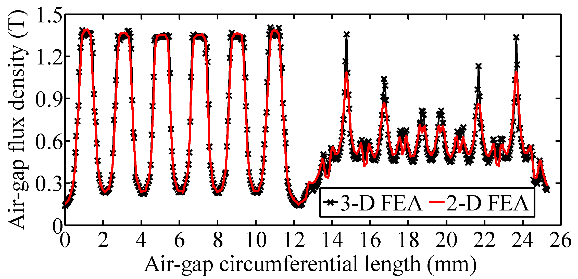
Figure 11 shows the comparison results of air-gap PM flux density distribution of pole A and (−A) calculated by 3-D and 2-D FEA using 3-D and both 2-D equivalent motor model of sub-motor1. It can be seen that the 2-D FEA results coincide well with the 3-D FEA ones by adjusting the stator PM parameters, which verifies the accuracy of both 2-D motor models. In addition, supposing that the dimensions of the tooth-layer region (the most intense area for magnetic field variation) are changed and all the other design parameters remain the same, the air-gap PM flux density can be still predicted well by 2-D FEA, as shown in Figure 12, in which, g is the air-gap length, wt is the tooth width, and tps is the stator tooth pitch. Thus, the proposed 2-D equivalent motor model, both accurate and simplified one, is characterized by high accuracy and good versatility.
Figure 13 shows the comparison of holding torque and torque-angle property calculated by 3-D and 2-DFEA, neglecting the mutual influence of PM leakage flux between two sub-motors. It can be seen that the 2-D FEA results coincide well with the 3-D FEA ones for the currents below and a little higher than the rated one (about 4.5 A in amplitude), which verifies the accuracy of the simplified 2-D equivalent motor model. However, calculation error of the 2-D model becomes larger and cannot be neglected for high currents, mainly due to the fact that the total flux generated by stator PMs and currents is inherently distributed in a same radial-circumferential plane in the 2-D model, leading to much easier and faster iron saturation of its stator pole and yoke region compared with the 3-D model [22]. To solve this problem, the dimensions of stator pole and yoke region of the 2-D equivalent motor model can be appropriately adjusted with the variation of winding currents based on the theoretical analysis in [22].
Consequently, the proposed 2-D equivalent motor model and corresponding 2-D FEA can be used for the motor’s initial electromagnetic design and performance analysis, which can effectively take into account of the end effect, the saturation effect, and the influence of coupling PM leakage flux, save the computing time and reduce the computer configuration requirements.
4.2. Experimental Results
Figure 14 shows the comparison of calculated and measured no-load back-EMF. The former is obtained by2-D FEA at θ = 49.5° (sub-motor1) and θ = 45° (sub-motor2), taking into account of the PM leakage flux influence (accurate 2-D model) or not (simplified 2-D model). To sub-motor1, although the PM leakage flux influence on the EMF of phase A reaches the maximum at θ = 49.5° (see Figure 10), which can be almost neglected according to the 2-D FEA results. There are some errors in EMF amplitude between the calculated and measured results, mainly due to the mismachining tolerance. In addition, both the calculated and measured EMF waveforms have good sine property due to the tooth-layer permeance harmonics have been weakened by using unequal-tooth-pitch method [23], which proves to be favorable to reduce the torque ripple and improve the operating stability as well as positioning resolutions.
The motor driver uses a micro-stepping drive, which divides one circle of the existing current by Nd steps, Nd is the number of divisions. The ideal positioning resolution is defined by (rotor tooth pitch)/Nd. Figure 15 shows the measured current waveforms at speed of 100 rpm under different Nd, which obtain good sine property when Nd ≥ 32. The ideal positioning resolution of both sub-motors corresponding to Nd = 4, Nd = 32 and Nd = 256, is 1.8°, 0.225°, 0.0281°, respectively. However, the actual positioning resolutions depends on several influencing factors, such as machining accuracy, driver performance, load condition, output torque stability, etc. Still much more research regarding to the positioning resolution deserves to be carried out in future works. And obviously, the proposed 2-D equivalent motor models and corresponding 2-D FEA can serve as important analysis tool.
5. Performance Analysis by 2-D FEA
5.1. Harmonic Analysis of Tooth-Layer Permeances
The parallel tooth-layer permeances of one stator pole (e.g., pole A) in equal-tooth-pitch and unequal-tooth-pitch situation can be respectively expressed as:
where ls is the stator core length, Zs is the stator teeth number per pole, Λt0 and Λtn are the constant and nth tooth-layer permeance components, Δθ is the difference value of stator tooth pitch to rotor tooth pitch. According to Equation (5), the harmonics can be effectively weakened supposing that Δθ is appropriately selected, whether the iron core is in saturation or not.
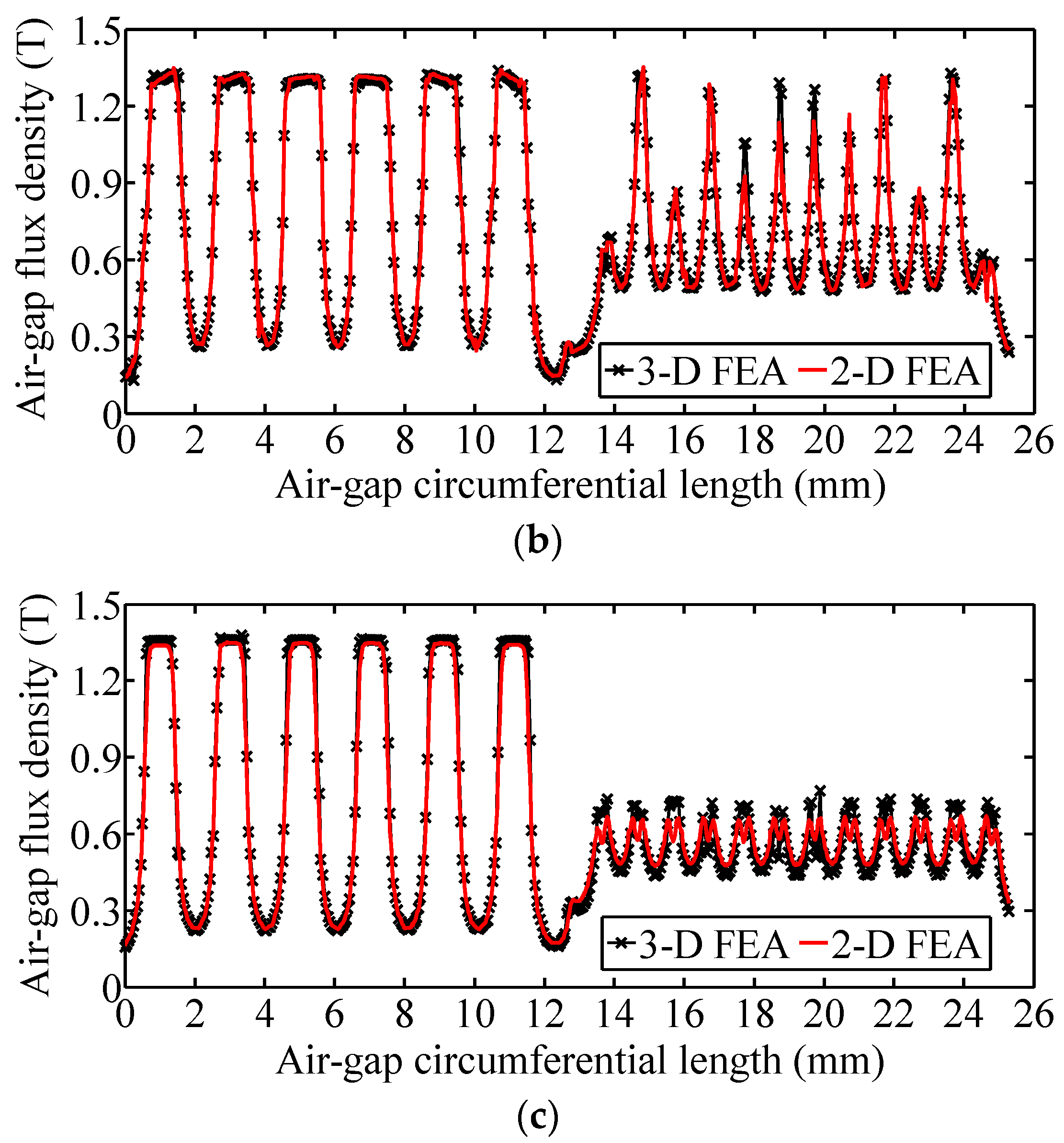
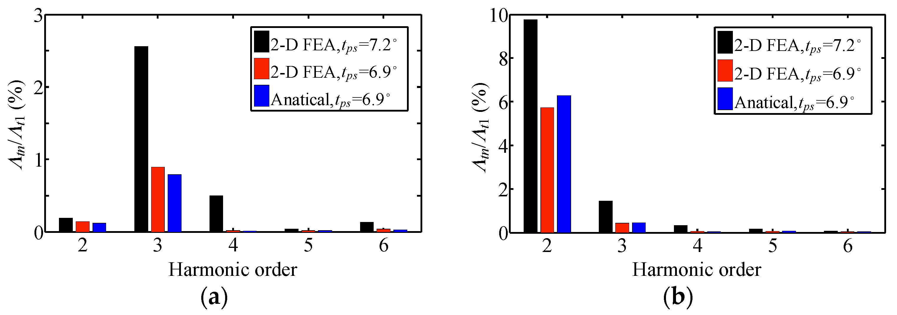
Figure 16 shows the harmonic analysis results of the parallel tooth-layer permeances of pole A under equal-tooth-pitch and unequal-tooth-pitch situation, taking into account of iron saturation (Bδ = 2 T) or not (Bδ = 0.2 T). In which, the analytical results are obtained by Equation (5) based on the 2-D FEA results of equal tooth pitch (tps = 7.2°). It can be seen that the harmonics are weakened by using the unequal-tooth-pitch method in all situations and that the analytical results coincide well with those obtained by 2-D FEA, which verifies the theoretical analysis.
5.2. Detent Torque
According to Equation (5), the Λa_unequal can be alternatively expressed as:
where Λa0 and Λan are the constant and nth parallel tooth-layer permeance components of pole A in unequal-tooth-pitch situation. Based on the harmonic analysis of tooth-layer permeances by 2-D FEA, the following parameters can be determined: Λa0 = 38.2 μWb/A (sub-motor1), Λa1 = 6.1 μWb/A (sub-motor1), Λa0 = 25.4 μWb/A (sub-motor2), Λa1 = 4.2 μWb/A (sub-motor2), and Λan (n = 2, 3, 4, 5, 6) can be obtained according to Figure 16.
In terms of [14,22], the stored PM energy in the air gap of each sub-motor can be expressed as:
where Fδ = gBδ/μ0 is the air-gap PM magnetomotive force (MMF). Accordingly, the detent torque can be derived by Equation (2) as:
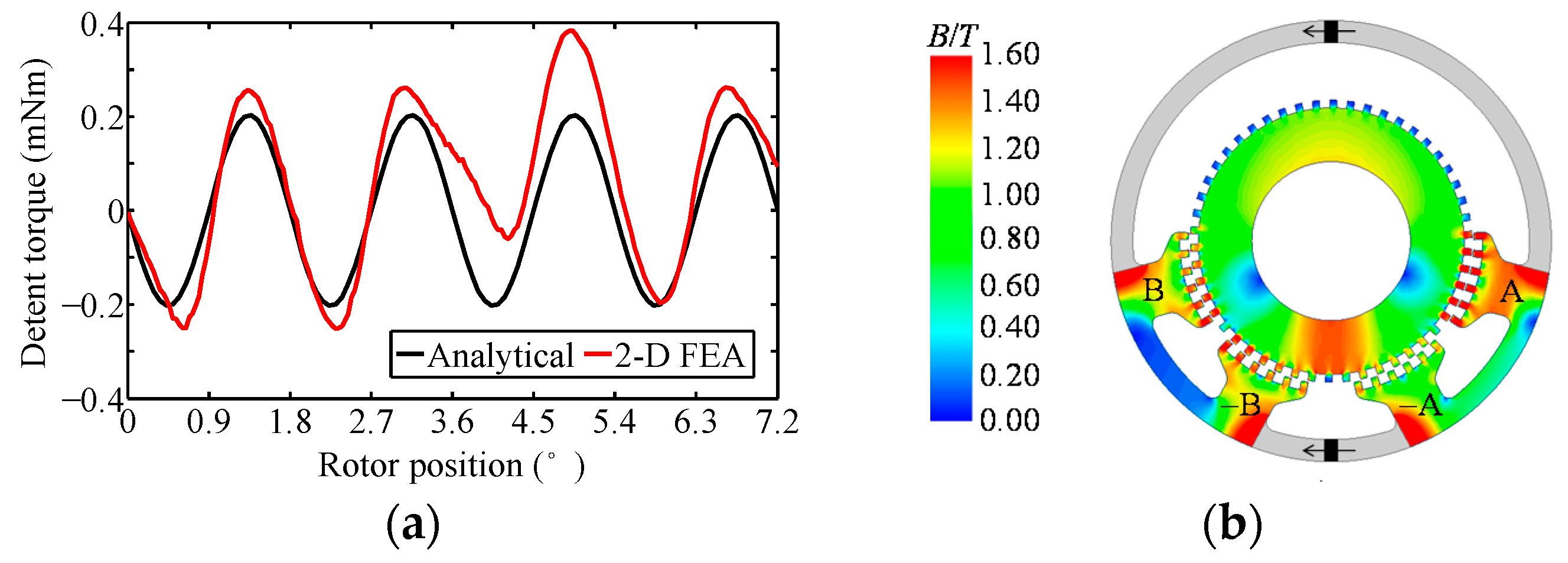
Figure 17a shows the comparison result of detent torque of sub-motor1 calculated by2-D FEA and Equation (8) at one tooth-pitch cycle, neglecting the influence of PM leakage flux between the two sub-motors. Figure 17b shows the no-load magnetic field distribution of the simplified 2-D equivalent motor model obtained by 2-D FEA. It can be seen that the maximum flux density of the stator and rotor teeth has reached about 1.6 T (already saturated for the core material), and the non- linearity B-H change will lead to distortion of the detent torque waveform, which is verified by the 2-D FEA result, whilst the analytical result is only applicable for the linear situation.
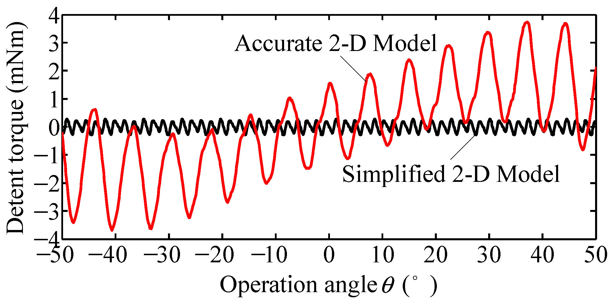
Figure 18 shows the calculated detent torque of sub-motor1 (Tcog1) by2-D FEA at the whole operation range, taking into account of the influence of PM leakage flux (accurate 2-D model) or not (simplified 2-D model). It can be seen that the PM leakage flux of sub-motor2 will lead to non- uniform and non-periodic distribution characteristics of Tcog1, which increase Tcog1 to a large extent. Especially at the operation range of θ = (−50–−40°), θ = (40–50°), where the most severe saturation region of the rotor core serves as one part of the closed magnetic circuit of phase B or phase A (see Figure 10), this influence reaches the maximum and so does the amplitude of the detent torque. In addition, the average value of detent torque in one tooth-pitch range (except the one at θ = 0°) is no longer zero, namely, the detent torque will provide effective torque even when the motor is in no- load condition, which may reduce the positioning resolution.
5.3. Holding Torque and Torque-angle Property
In terms of [14,22], the PM flux and self-inductance of each sub-motor can be derived from the simplified equivalent magnetic circuit as:
where Np is the number of winding turns per stator pole.
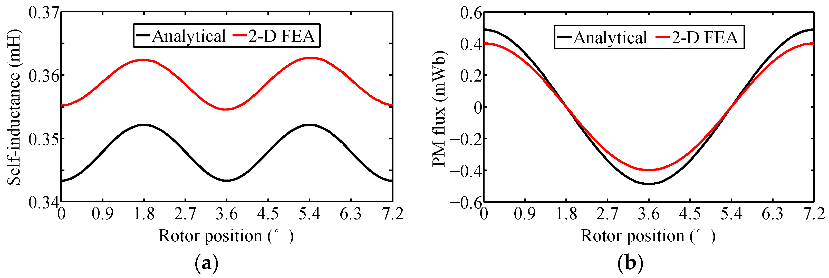
Figure 19 shows the comparison results of self-inductance and PM flux of sub-motor1 obtained by analytical method and 2-D FEA. It can be seen that the calculated Laa by Equation (10) coincides well with the 2-D FEA one in linear condition (about 3% in error), due to the linearity of B-H curve. However, the calculated ψpma by Equation (9) is obviously bigger than the 2-D FEA one (about 22% in error), due to the nonlinearity B-H change (see Figure 17b) has increased the reluctance of the PM magnetic circuit, and this effect can be accurately reflected by the 2-D FEA.
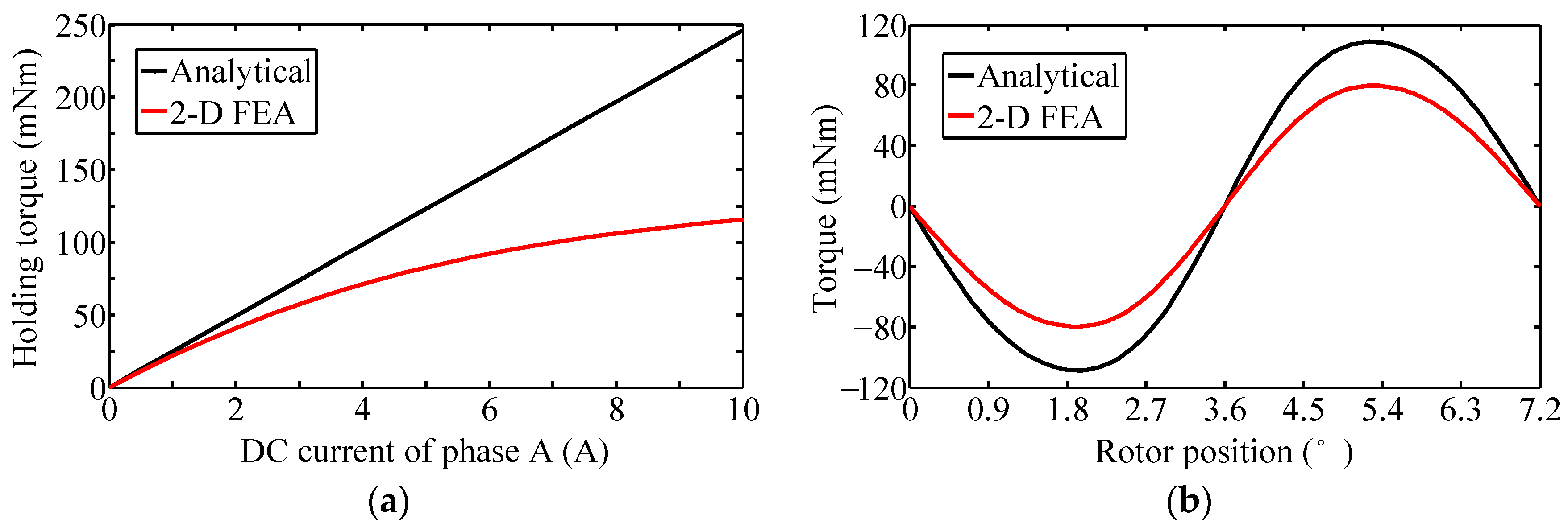
According to Equations (2), (8)–(10), the holding torque and torque-angle property can be obtained when single phase is energized with DC current, e.g., ia = Idc and ib = 0, which are compared with the 2-D FEA results as shown in Figure 20. It can be seen that the analytical calculation error caused by the nonlinearity B-H change increases rapidly with the current, about 35% and 112% for the rated and maximum current, respectively. Therefore, although the analytical method has great advantages, such as providing results almost instantaneously, the physical background underlying the calculation can be usually traced, and the cause and effect are well-defined, it reaches the limit when the saturation effect has to be taken into account. In this case, the proposed 2-D FEA has a distinct advantage over the analytical method, and a coefficient considering the nonlinearity B-H change should be adopted to revise the analytical calculation, which can be easily obtained from the holding torque comparison results as illustrated in Figure 20a.
5.4. Pull-out Torque
According to Equations (2), (8)–(10), the maximum pull-out torque can be obtained when both two phases are energized with rated sinusoidal currents ia = Imcos(θ + δ) and ib = Imsin(θ + δ) at δ = π/2, which is compared with the 2-D FEA result as shown in Figure 21. The torque ripple can be defined as Trip = Tmax − Tmin, where Tmax, Tmin are the maximum, minimum value of the pull-out torque. It can be seen that the analytical calculation error of average pull-out torque (Tavg) caused by the nonlinearity B-H change is about 35% (sub-motor1), 29% (sub-motor2). Moreover, Trip of sub-motor1 obtained by analytical calculation and 2-D FEA is respectively 7.2 mN·m, 8.1 mN·m, and Trip of sub-motor2 is respectively 1.9 mN·m, 2.3 mN·m. Consequently, the nonlinearity B-H change mainly influences the average value of pull-out torque, and therefore the analytical calculation with correction coefficient obtained from the holding torque comparison results can be adopted to approximately predict the pull-out torque property at different currents.
Figure 22 shows the maximum pull-out torque calculated by 2-D FEA at half operation range with rated sinusoidal current excitation. Supposing that the torque ripple factor can be determined as KT = Trip/Tavg [24], it can be seen KT of sub-motor1 with and without the influence of the PM leakage flux of sub-motor2 is 10.1%, 24.3%, respectively, and KT of sub-motor2 is 10.7%, 17.6%, respectively.
The increased torque ripple will inevitably decrease the operation performance, e.g., increase the vibration and noise and reduce the positioning resolution, which deserves to be minimized by weakening the coupling PM leakage flux between two sub-motors via optimal design.
5.5. Unbalanced Force
Due to the gravity effect, the stator of sub-motor2 will produce unbalanced force during the operation, as shown in Figure 1. To approximately evaluate this influence, the stator of sub-motor2 is simplified for analysis, as shown in Figure 23.
Accordingly, the unbalanced torque produced by the unbalanced force along X-axis and Y-axis can be respectively derived as:
where ρFe is the iron density, gc is the gravitational constant, Dsi and Dso are inner and outer stator diameter, θ1 and θ2 are the operation angle of sub-motor1 and sub-motor2, respectively. Figure 24 shows the variation of TX and TY in the range of θ1 = θ2 = (−50–50°). It can be seen that the maximum value of the unbalanced torque (about 2.56 mN·m) is much smaller than the rated pull-out torque, especially taking into account of the fact that the air-gap length can be much smaller and the torque producing ability much higher after motor design optimization, i.e., the influence of gravity effect can be almost neglected for this kind of 2-DOF motor.
On the other hand, based on Maxwell Stress Method [25], the normal force Fn and tangential force Ft of the magnetic stress acting on surface S can be respectively expressed as:
where Bn and Bt are the normal and tangential component of air-gap flux density.
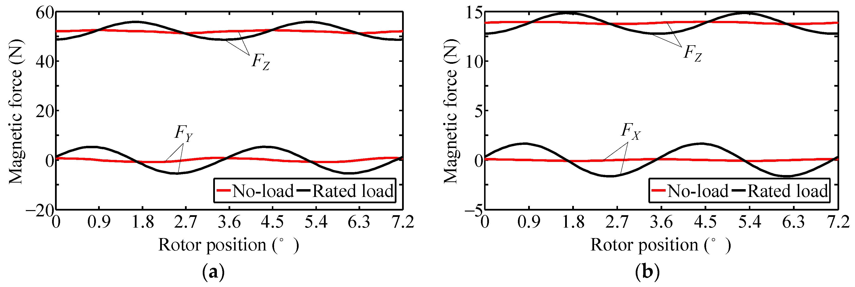
Since the simplified 2-D equivalent motor model can predict well the air-gap PM flux density distribution and has the same stator pole position as the 3-D motor model, it is suitable to be used for magnetic stress analysis. Figure 25 shows the calculated magnetic stress by 2-D FEA at θ1 = θ2 = 0°, where the centerline of output shaft coincides with Z-axis. It can be seen that the average magnetic force along X-axis and Y-axis is zero, due to the structural symmetry of stator with respect to the baseline. However, the average magnetic force along Z-axis (unilateral magnetic pull) is relatively big to the motor volume, which should be effectively balanced by the small bearings. Moreover, the magnetic force fluctuation in load condition is much bigger than the no-load one, even along X-axis and Y-axis, which may cause some problems such as vibration and noise during the operation.
6. Conclusions
This paper has proposed a novel spherical 2-DOF hybrid stepping motor and its 2-D equivalent magnetic field analysis method. Taking into account of theoretical, FEA and experimental studies, conclusions can be obtained as follows:
- The developed 2-DOF motor has advantages such as simple assembling, relatively simple and compact mechanical structure, easy open-loop control, etc., whereas it has the disadvantages of relatively lower mechanical robustness and higher frictional resistance due to the specially designed bearing structure, which should be further improved via the bearing structure optimal design to meet the requirements for practical engineering applications.
- The coupling magnetic field between two sub-motors is mainly the PM leakage flux produced at the PM opening place of each sub-motor, which mainly influences the rotor’s magnetic field distribution and can lead to performance reduction, e.g., increases torque ripple and reduces positioning resolution, and which should be minimized via optimal design.
- The accurate 2-D equivalent motor model can take into account of the mutual influence of PM leakage flux between the two sub-motors, whereas is only suitable for solving static and steady state problem. The simplified 2-D equivalent motor model can realize 2-phase operation and solve the transient problem, which is more universally used for expected situations where the mutual influence of PM leakage flux can be almost neglected via optimal design.
- The proposed 2-D equivalent magnetic field analysis method is characterized by time-saving, high accuracy and good versatility, its calculation error produced at high currents situation is mainly caused by different PM and current magnetic field distribution characteristics between the 2-D and 3-D model, which can be corrected by adjusting the dimension of stator pole and yoke region of the 2-D model with the variation of winding currents.
- The unbalanced force caused by gravity effect can be almost neglected, whereas the unilateral magnetic pull is relatively big to the motor’s volume, which may cause some problems such as vibration and noise during the operation, especially at high speed.
Acknowledgments
This work was supported in part by the foundation of National High Technology Research and Development Program of China (863 Program) under Projects 2015AA042307.
Author Contributions
Binglin Lu mainly conducted the analysis of the proposed spherical 2-DOF hybrid stepping motor and performed the experiments and FEA simulations. The manuscript was improved and revised by Yanliang Xu.
Conflicts of Interest
The authors declare no conflict of interest.
References
- Williams, F.C.; Laithwaite, E.R.; Eastham, J.F. Development and design of spherical induction motors. Proc. Inst. Elect. Eng. 1959, 106, 471–847. [Google Scholar] [CrossRef]
- Davey, K.; Vachtsevanos, G.; Powers, R. The analysis of fields and torques in spherical induction motors. IEEE Trans. Magn. 1987, 23, 273–282. [Google Scholar] [CrossRef]
- Lee, K.M.; Kwan, C.K. Design concept development of a spherical stepper for robotic applications. IEEE Trans. Robot. Autom. 1991, 7, 175–181. [Google Scholar] [CrossRef]
- Wang, W.; Wang, J.; Jewell, G.W.; Howe, D. Design and control of a novel spherical permanent magnet actuator with three degrees of freedom. IEEE/ASME Trans. Mechatron. 2003, 8, 457–468. [Google Scholar] [CrossRef]
- Wang, J.; Jewell, G.W.; Howe, D. A novel spherical actuator: Design and control. IEEE Trans. Magn. 1997, 33, 4209–4211. [Google Scholar] [CrossRef]
- Wang, J.; Wang, W.; Jewell, G.W.; Howe, D. A novel spherical actuator with three degrees-of-freedom. IEEE Trans. Magn. 1998, 34, 2078–2080. [Google Scholar] [CrossRef]
- Chirikjian, G.S.; Stein, D. Kinematic design and commutation of a spherical stepper motor. IEEE/ASME Trans. Mechatron. 1999, 4, 342–353. [Google Scholar] [CrossRef]
- Kahlen, K.; Voss, I.; Priebe, C.; De Doncker, R.W.D. Torque control of a spherical machine with variable pole pitch. IEEE Trans. Power Electron. 2004, 19, 1628–1634. [Google Scholar] [CrossRef]
- Yan, L.; Chen, I.M.; Yang, G.; Lee, K.M. Analytical and experimental investigation on the magnetic field and torque of a permanent magnet spherical actuator. IEEE/ASME Trans. Mechatron. 2006, 11, 409–419. [Google Scholar]
- Putwanto, E.; Toyama, S. Control Method of a Spherical Ultrasonic Motor. In Proceedings of the 2003 International Conference on Advanced Intelligent Mechatronics (AIM), Kobe, Japan, 20–24 July 2003; pp. 1321–1326. [Google Scholar]
- Takemura, K.; Maeno, T. Characteristics of an Ultrasonic Motor Capable of Generating a Multi-Degrees of Freedom Motion. In Proceedings of the 2000 International Conference on Robotics and Automation (ICRA), San Francisco, CA, USA, 24–28 April 2000; pp. 3660–3665. [Google Scholar]
- Shi, L.; Motomura, Y. A Small-Sized Spherical Stepping Motor and the Controls. In Proceedings of the 2003 International Conference on Electrical Machines and Systems (ICEMS), Beijing, China, 9–11 November 2003; pp. 191–194. [Google Scholar]
- Yano, T.; Suzuki, T. Basic characteristics of the small spherical stepping motor. In Proceedings of the 2002 International Conference on Intelligent Robots and Systems, Lausanne, Switzerland, 30 September–4 October 2002; pp. 1980–1985. [Google Scholar]
- Matsui, N.; Nakamura, M.; Kosaka, T. Instantaneous torque analysis of hybrid stepping motor. IEEE Trans. Ind. Appl. 1996, 32, 1176–1182. [Google Scholar] [CrossRef]
- Lim, K.C.; Hong, J.P.; Kim, G.K. Characteristic analysis of 5-phase hybrid stepping motor considering the saturation effect. IEEE Trans. Magn. 2001, 37, 3518–3521. [Google Scholar]
- Jang, K.B.; Lim, S.Y.; Lim, T.B.; Jin, C.S.; Cho, Y.H.; Kim, Y.T.; Lee, J. 2-D FE analysis of hybrid stepping motor using virtual magnetic barrier. IEEE Trans. Magn. 2003, 39, 3268–3270. [Google Scholar] [CrossRef]
- Kang, S.G.; Lieu, D.K. Torque Analysis of Combined 2D FEM and Lumped Parameter Method for a Hybrid Stepping Motor. In Proceedings of the 2005 International Conference on Electric Machines and Drives, San Antonio, TX, USA, 15 May 2005; pp. 1199–1203. [Google Scholar]
- Stuebig, C.; Ponick, B. Comparison of calculation methods for hybrid stepping motors. IEEE Trans. Ind. Appl. 2012, 48, 2182–2189. [Google Scholar] [CrossRef]
- Kosaka, T.; Pollock, C.; Matsui, N. 3 Dimensional Finite Element Analysis of Hybrid Stepping Motors Taking Inter-Lamination Gap into Account. In Proceedings of the 2004 International Conference on Power Electronics, Machines & Drives (PEMD), Edinburgh, UK, 31 March–2 April 2004; pp. 534–539. [Google Scholar]
- Lu, B.; Xu, Y.; Feng, X.; Gong, X. A New Calculation Method for Electromagnetic Torque of Stepping Motors—Teeth Layer Calculated Torque Method. In Proceedings of the 2014 International Conference on Electrical Machines and Systems (ICEMS), Hangzhou, China, 22–25 October 2014; pp. 1652–1656. [Google Scholar]
- Freitas, M.A.A.; Andrade, D.A.; Borges, T.T. Driving the Step Motor with Controlled Phase Currents. In Proceedings of the 1998 International Conference on Power Electronic Drives and Energy Systems for Industrial Growth (PEDES), Perth, Australia, 1–3 December 1998; pp. 493–498. [Google Scholar]
- Lu, B.; Xu, Y. Presentation and performance evaluation of a novel stator-permanent-magnet hybrid stepping motor. Energies 2017, 10, 693. [Google Scholar]
- Rajagopal, K.R.; Singh, B.; Singh, B.P. Optimal tooth-geometry for specific performance requirements of a hybrid stepper motor. IEEE Trans. Magn. 2003, 39, 3010–3012. [Google Scholar] [CrossRef]
- Chau, K.T.; Sun, Q.; Fan, Y.; Cheng, M. Torque ripple minimization of doubly salient permanent-magnet motors. IEEE Trans. Energy Convers. 2005, 20, 352–358. [Google Scholar] [CrossRef]
- Sun, X.; Xue, Z.; Zhu, J.; Guo, Y.; Yang, Z.; Chen, L.; Chen, J. Suspension force modeling for a bearingless permanent magnet synchronous motor using Maxwell stress tensor method. IEEE Trans. Appl. Supercond. 2016, 26, 0608705. [Google Scholar] [CrossRef]
Figure 1.
The developed spherical 2-DOF (two-degree-of-freedom) hybrid stepping motor. (a) Configuration; (b) Diagram of the 2-DOF motion trajectory.
Figure 1.
The developed spherical 2-DOF (two-degree-of-freedom) hybrid stepping motor. (a) Configuration; (b) Diagram of the 2-DOF motion trajectory.

Figure 2.
Structure decomposition diagram of the 2-DOF motor. (a) Sub-motors; (b) Rotors.
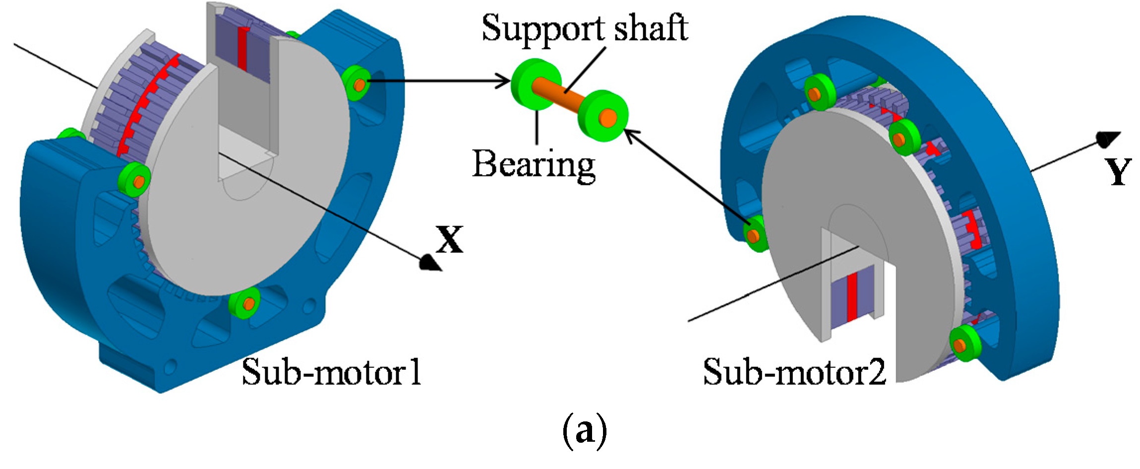
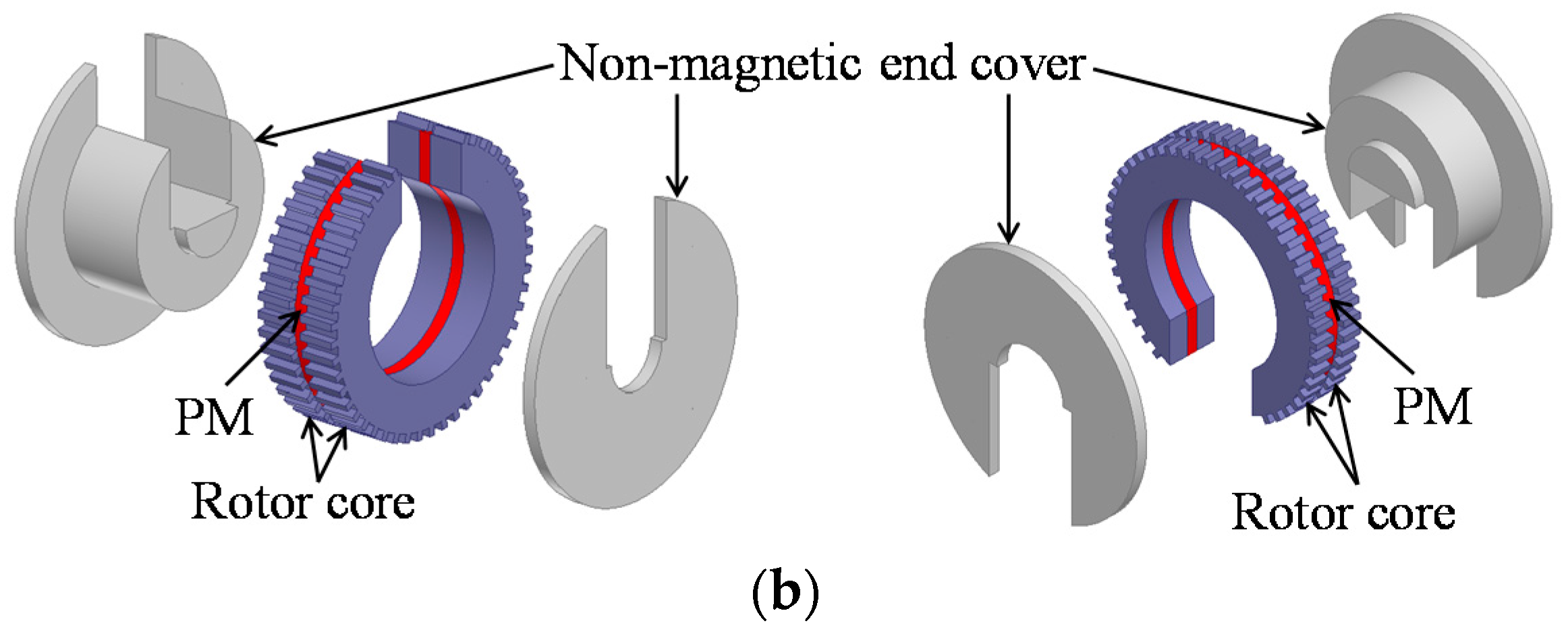
Figure 3.
Magnetic field distribution produced by the PM of sub-motor2.

Figure 4.
3-D equivalent motor model of sub-motor1. (a) Diagram; (b) Sectional view of the motor part with N-pole rotor; (c) Sectional view of the motor part with S-pole rotor.
Figure 4.
3-D equivalent motor model of sub-motor1. (a) Diagram; (b) Sectional view of the motor part with N-pole rotor; (c) Sectional view of the motor part with S-pole rotor.
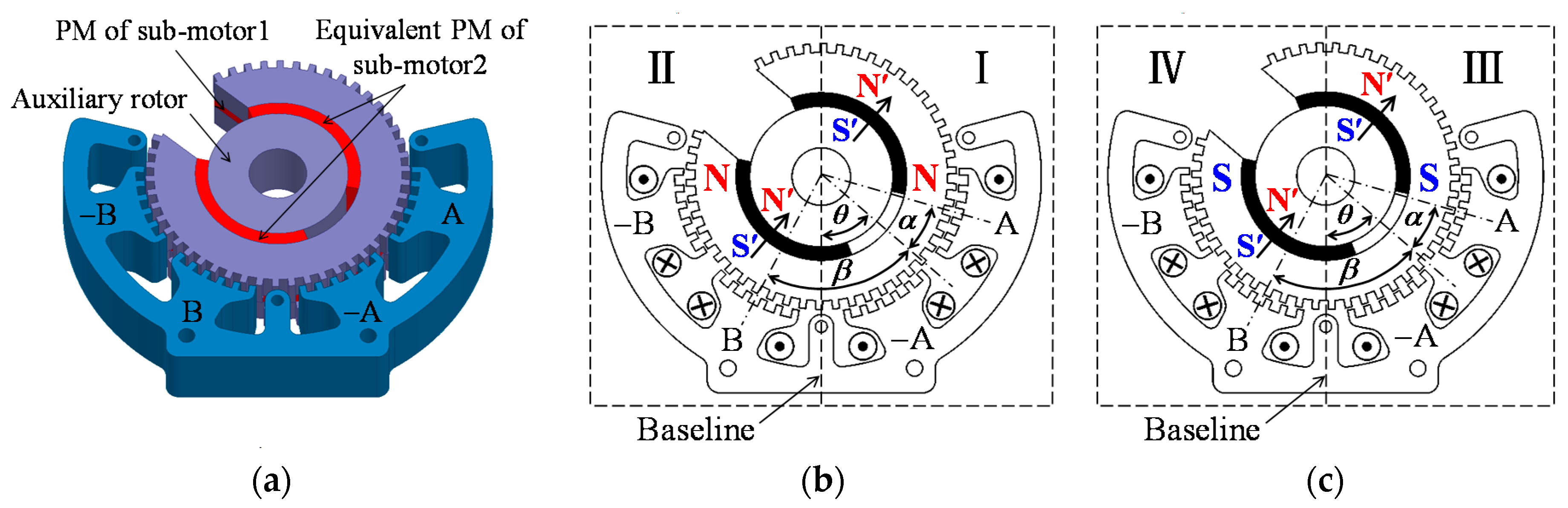
Figure 5.
Accurate 2-D equivalent motor model of sub-motor1. (a) 2-D model of part I; (b) 2-D model of part II; (c) 2-D model of part III; (d) 2-D model of part IV.
Figure 5.
Accurate 2-D equivalent motor model of sub-motor1. (a) 2-D model of part I; (b) 2-D model of part II; (c) 2-D model of part III; (d) 2-D model of part IV.
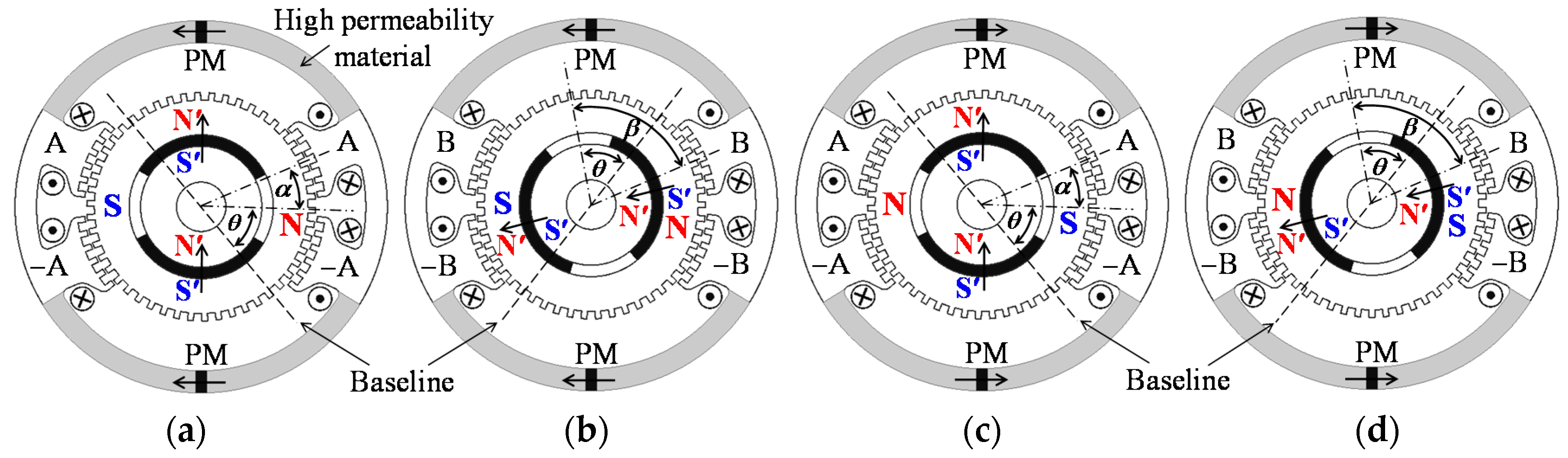
Figure 6.
Simplified 2-D equivalent motor model of sub-motor1. (a) Equivalent form of Figure 4c; (b) The simplified 2-D motor model corresponding to part I + VI.
Figure 6.
Simplified 2-D equivalent motor model of sub-motor1. (a) Equivalent form of Figure 4c; (b) The simplified 2-D motor model corresponding to part I + VI.
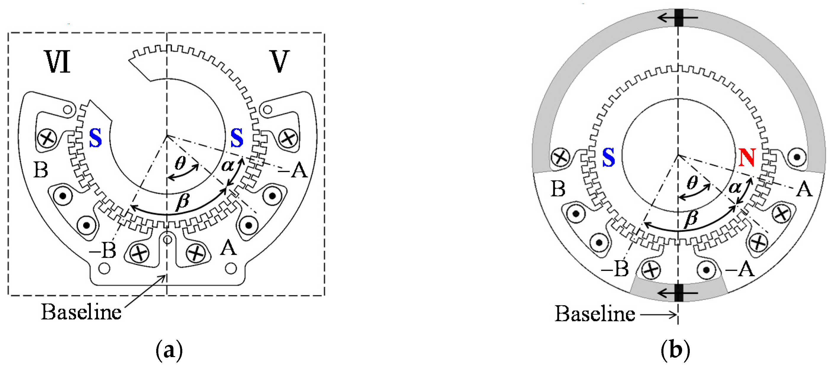
Figure 7.
Prototype of the developed spherical 2-DOF hybrid stepping motor.

Figure 8.
Prototypes of testing motors. (a) Testing motor of sub-motor1; (b) Testing motor of sub-motor2; (c) Stator of sub-motor1; (d) Stator of sub-motor2.
Figure 8.
Prototypes of testing motors. (a) Testing motor of sub-motor1; (b) Testing motor of sub-motor2; (c) Stator of sub-motor1; (d) Stator of sub-motor2.

Figure 9.
No-load calculation results obtained by 3-D FEA. (a) Magnetic field distribution produced by the PM of sum-motor1; (b) Mesh generation graph for sub-motor1; (c) Mesh generation graph for sub-motor2.
Figure 9.
No-load calculation results obtained by 3-D FEA. (a) Magnetic field distribution produced by the PM of sum-motor1; (b) Mesh generation graph for sub-motor1; (c) Mesh generation graph for sub-motor2.
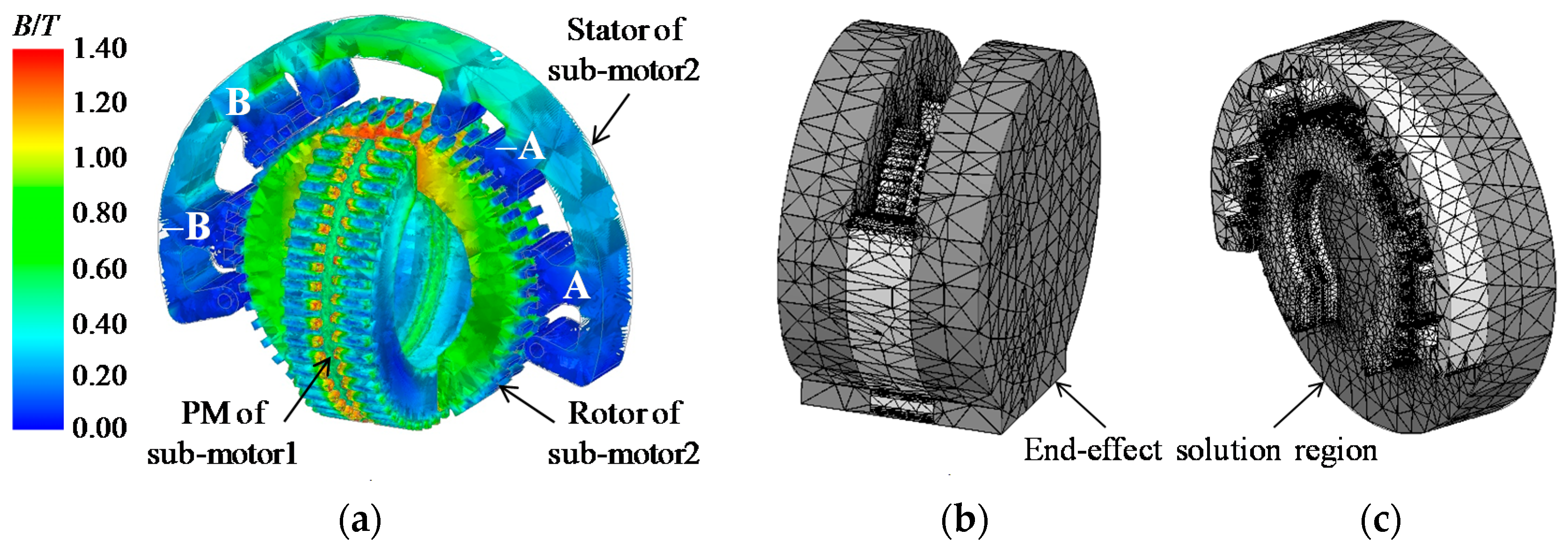
Figure 10.
Magnetic field distribution of the accurate 2-D equivalent motor model of sub-motor1 at θ = 49.5° produced by the rotor PMs.
Figure 10.
Magnetic field distribution of the accurate 2-D equivalent motor model of sub-motor1 at θ = 49.5° produced by the rotor PMs.
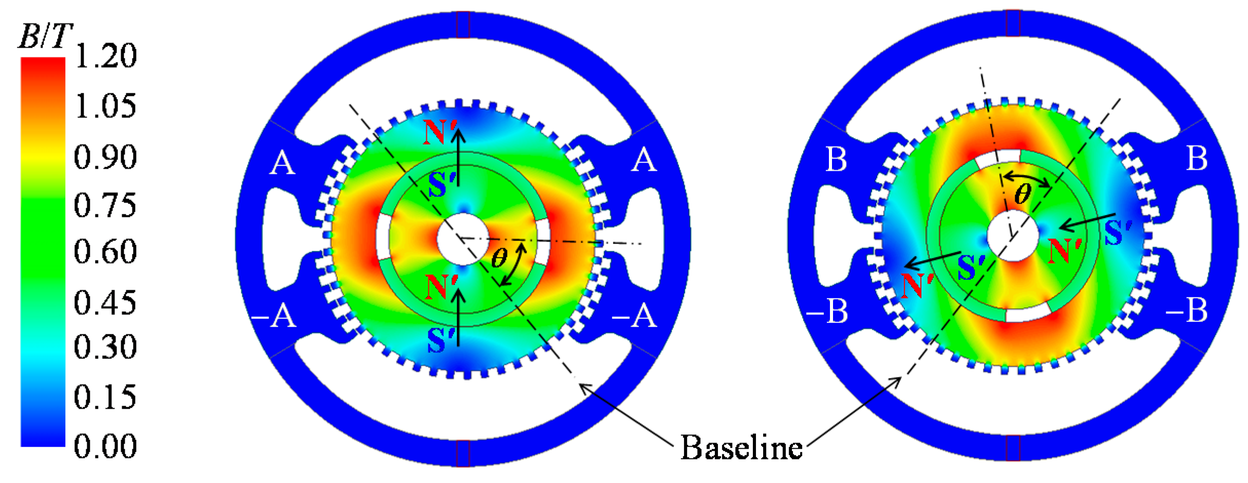
Figure 11.
Comparison of air-gap PM flux density of sub-motor1 by 3-D and 2-D FEA.

Figure 12.
Comparison of air-gap PM flux density of sub-motor1 after tooth-layer variation. (a) g = 0.1 mm, wt = 0.8 mm, tps = 6.9°; (b) g = 0.2 mm, wt = 1.0 mm, tps = 6.9°; (c) g = 0.2 mm, wt = 0.8 mm, tps = 7.2°.
Figure 12.
Comparison of air-gap PM flux density of sub-motor1 after tooth-layer variation. (a) g = 0.1 mm, wt = 0.8 mm, tps = 6.9°; (b) g = 0.2 mm, wt = 1.0 mm, tps = 6.9°; (c) g = 0.2 mm, wt = 0.8 mm, tps = 7.2°.
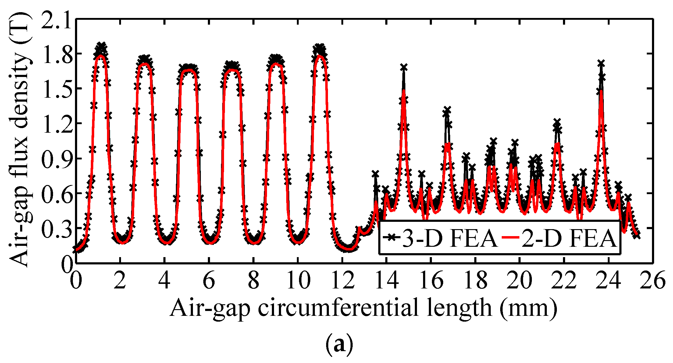

Figure 13.
Comparison of the torque properties by 3-D and 2-D FEA. (a) Holding torque property; (b) Torque-angle property with rated current excitations.
Figure 13.
Comparison of the torque properties by 3-D and 2-D FEA. (a) Holding torque property; (b) Torque-angle property with rated current excitations.
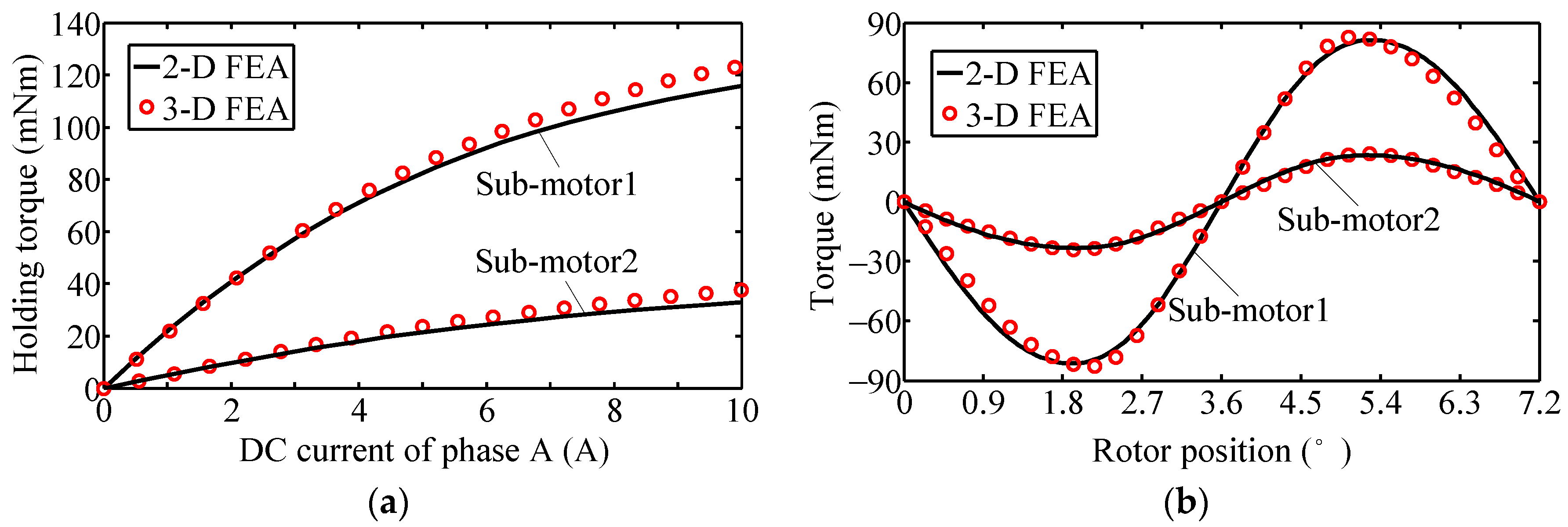
Figure 14.
Comparison of calculated and measured no-load back-EMF. (a) Calculated EMF of sub-motor1 at θ = 49.5°; (b) Measured EMF of sub-motor1; (c) Calculated EMF of sub-motor2 at θ = 45°; (d) Measured EMF of sub-motor2.
Figure 14.
Comparison of calculated and measured no-load back-EMF. (a) Calculated EMF of sub-motor1 at θ = 49.5°; (b) Measured EMF of sub-motor1; (c) Calculated EMF of sub-motor2 at θ = 45°; (d) Measured EMF of sub-motor2.
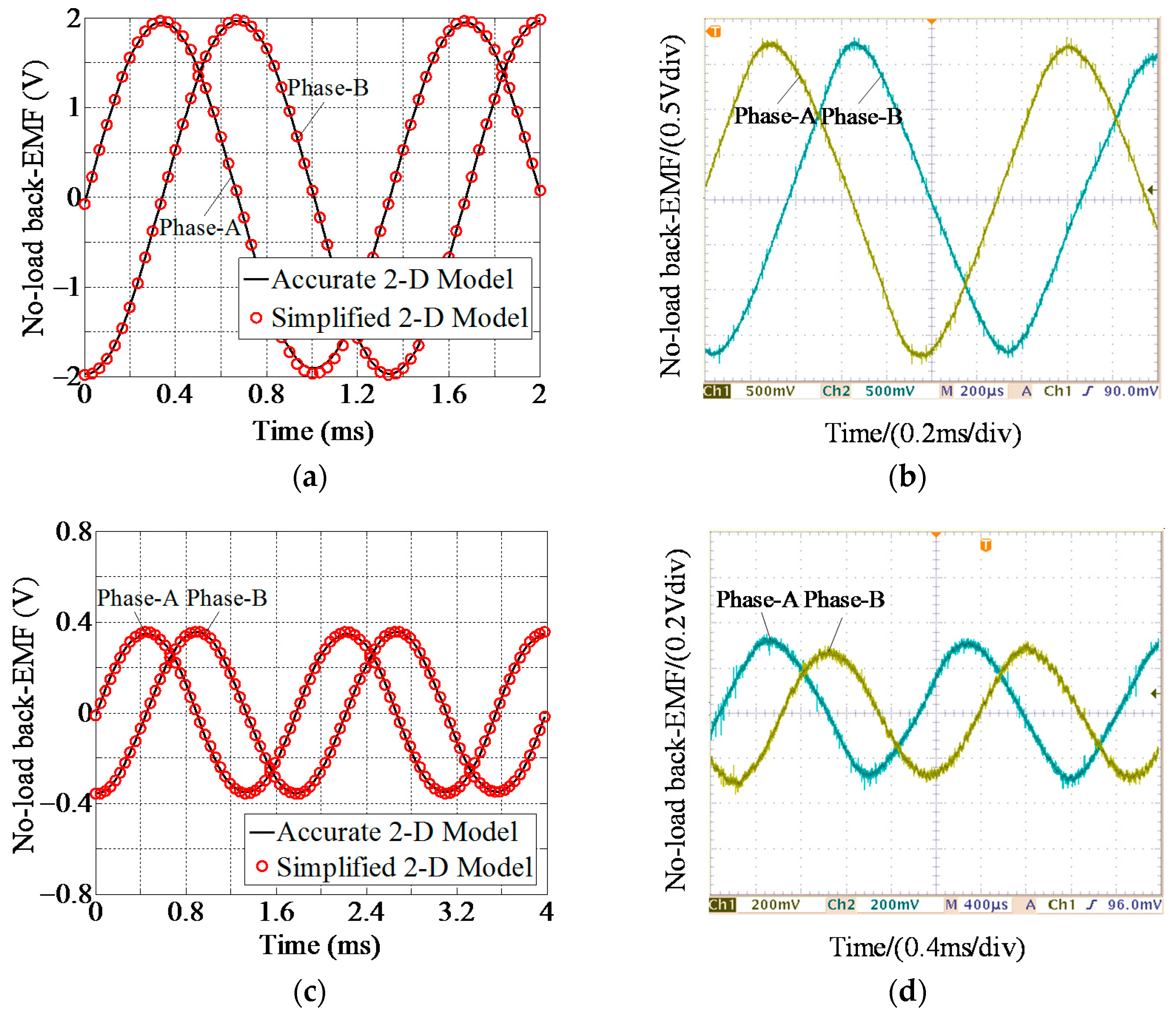
Figure 15.
Measured phase current waveforms at speed of 100 rpm under different divides of micro- stepping drive. (a) Nd = 4; (b) Nd = 32; (c) Nd = 256.
Figure 15.
Measured phase current waveforms at speed of 100 rpm under different divides of micro- stepping drive. (a) Nd = 4; (b) Nd = 32; (c) Nd = 256.
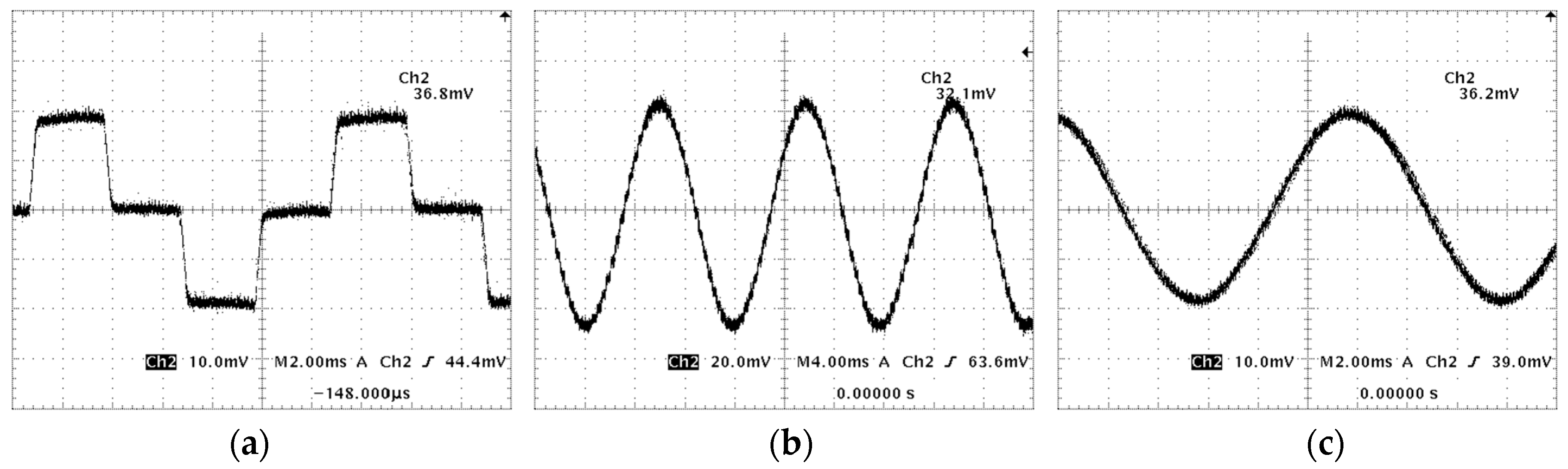
Figure 16.
Harmonic analysis of parallel tooth-layer permeances. (a) Sub-motor1, Bδ = 0.2 T, Δθ = π/12 (0.3°); (b) Sub-motor1, Bδ = 2 T, Δθ = π/12 (0.3°); (c) Sub-motor2, Bδ = 0.2 T, Δθ = π/9 (0.4°); (d) Sub-motor2, Bδ = 2 T, Δθ = π/9 (0.4°).
Figure 16.
Harmonic analysis of parallel tooth-layer permeances. (a) Sub-motor1, Bδ = 0.2 T, Δθ = π/12 (0.3°); (b) Sub-motor1, Bδ = 2 T, Δθ = π/12 (0.3°); (c) Sub-motor2, Bδ = 0.2 T, Δθ = π/9 (0.4°); (d) Sub-motor2, Bδ = 2 T, Δθ = π/9 (0.4°).

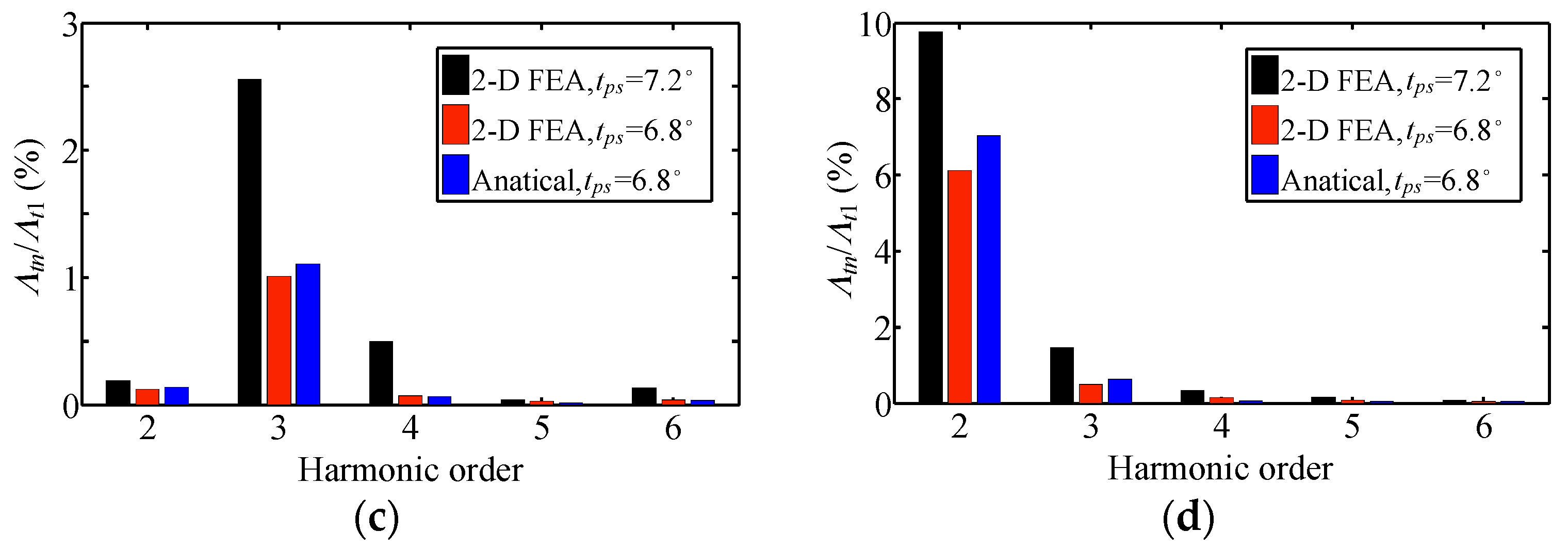
Figure 17.
Comparison of detent torque of sub-motor1 by analytical method and 2-D FEA. (a) Detent torque; (b) No-load magnetic field distribution of simplified 2-D equivalent model of sub-motor1.
Figure 17.
Comparison of detent torque of sub-motor1 by analytical method and 2-D FEA. (a) Detent torque; (b) No-load magnetic field distribution of simplified 2-D equivalent model of sub-motor1.

Figure 18.
Calculated detent torque of sub-motor1 by using 2-D FEA.

Figure 19.
Comparison of self-inductance and PM flux by analytical method and 2-D FEA. (a) Laa of sub-motor1; (b) ψpma of sub-motor1.
Figure 19.
Comparison of self-inductance and PM flux by analytical method and 2-D FEA. (a) Laa of sub-motor1; (b) ψpma of sub-motor1.

Figure 20.
Comparison of torque properties by analytical method and 2-D FEA. (a) Holding torque property of sub-motor1; (b) Torque-angle property of sub-motor1 with rated current excitation.
Figure 20.
Comparison of torque properties by analytical method and 2-D FEA. (a) Holding torque property of sub-motor1; (b) Torque-angle property of sub-motor1 with rated current excitation.

Figure 21.
Comparison of maximum pull-out torque by analytical method and 2-D FEA with rated sinusoidal current excitation. (a) Sub-motor1; (b) Sub-motor2.
Figure 21.
Comparison of maximum pull-out torque by analytical method and 2-D FEA with rated sinusoidal current excitation. (a) Sub-motor1; (b) Sub-motor2.
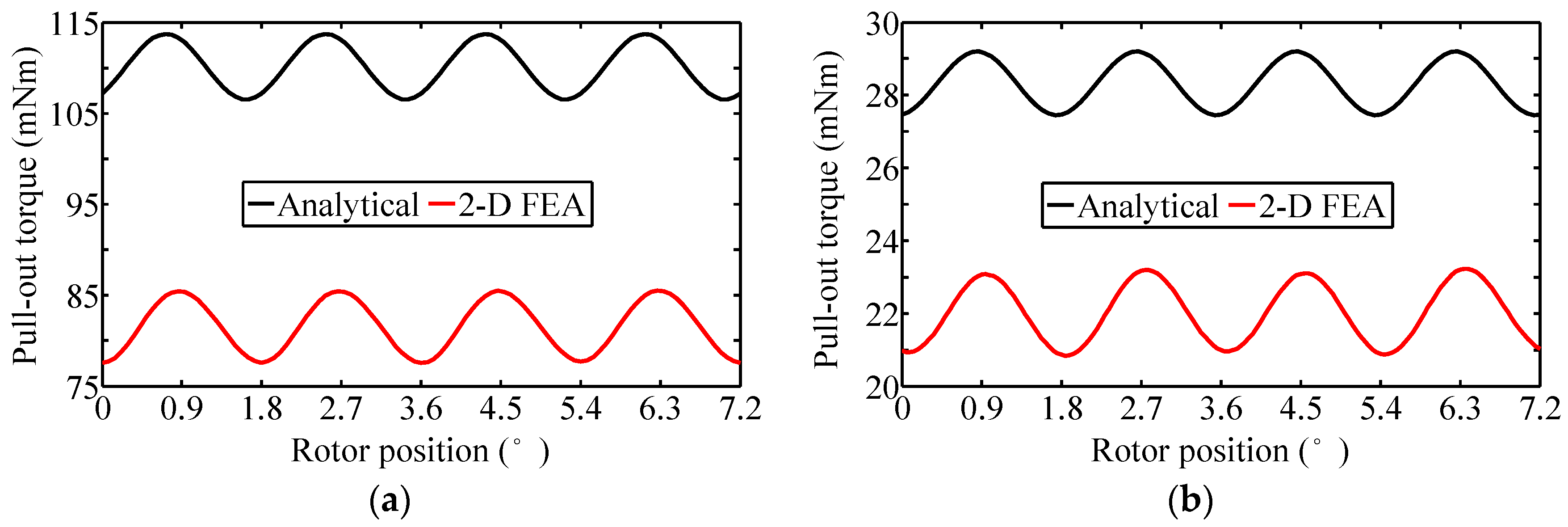
Figure 22.
Maximum pull-out torque calculated by 2-D FEA with rated sinusoidal current excitation. (a) Sub-motor1; (b) Sub-motor2.
Figure 22.
Maximum pull-out torque calculated by 2-D FEA with rated sinusoidal current excitation. (a) Sub-motor1; (b) Sub-motor2.
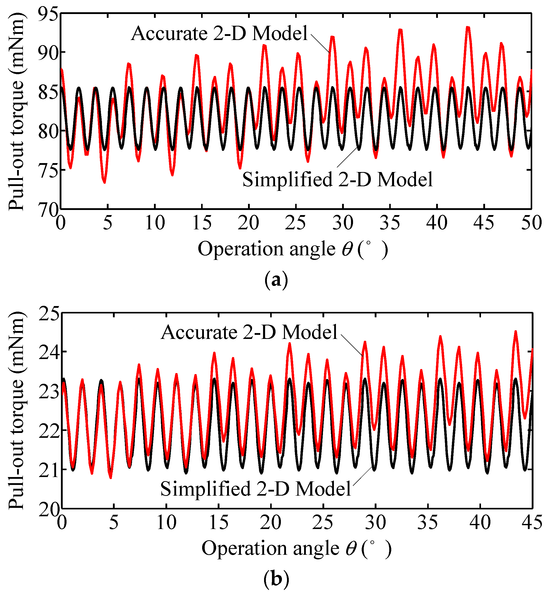
Figure 23.
Simplified motor model for unbalanced force analysis. (a) 2-DOF motor with simplified stator of sub-motor2; (b) Equivalent mass surface of the stator of sub-motor2.
Figure 23.
Simplified motor model for unbalanced force analysis. (a) 2-DOF motor with simplified stator of sub-motor2; (b) Equivalent mass surface of the stator of sub-motor2.
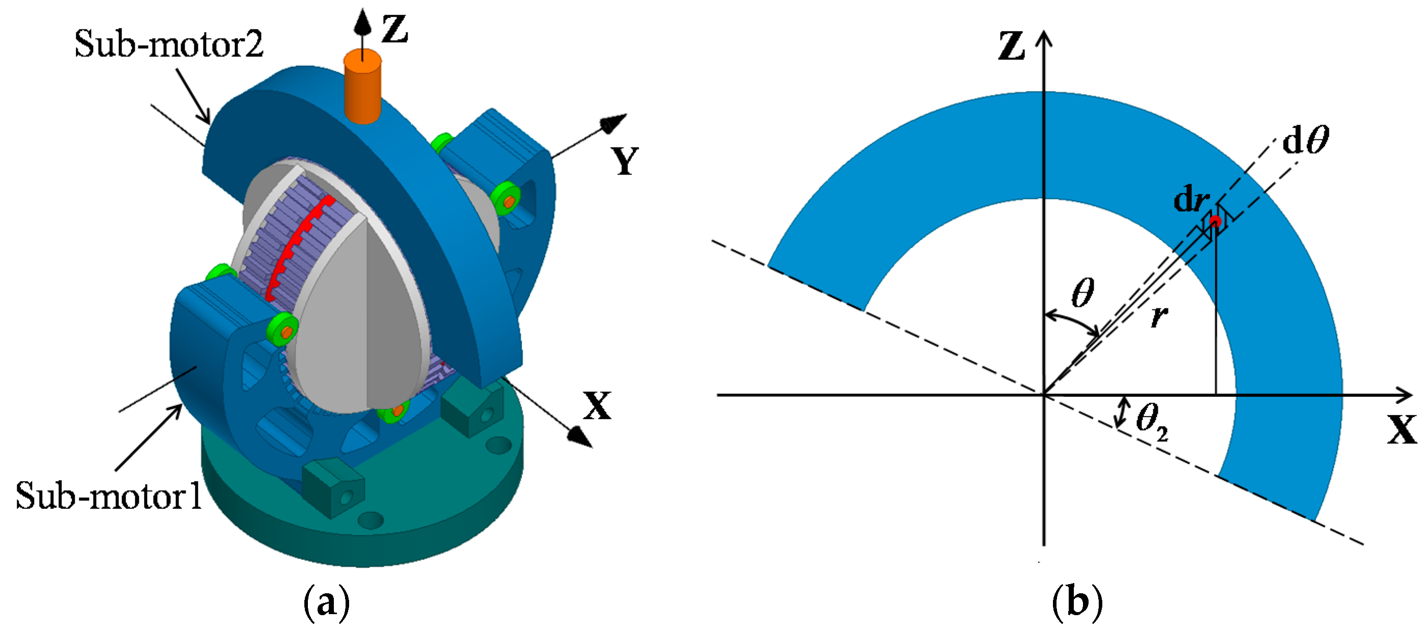
Figure 24.
Calculation results of unbalanced torque produced by gravity effect. (a) TX; (b) TY.
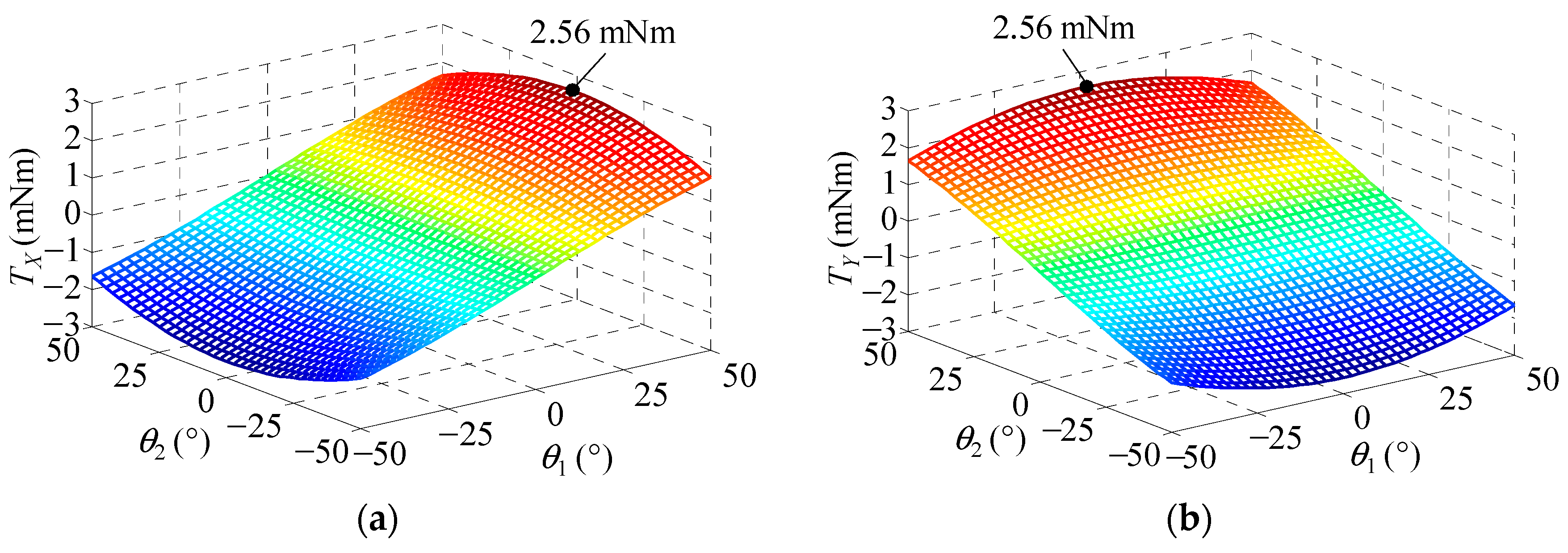
Figure 25.
Calculated magnetic stress by2-D FEA. (a) Sub-motor1; (b) Sub-motor2.

Table 1.
The same parameters of sub-motor1 and sub-motor2.
| Parameters | Value | Parameters | Value |
|---|---|---|---|
| Rated current (A) | 3.2 | Air-gap length (mm) | 0.2 |
| Rotor tooth pitch (°) | 7.2 | End cover diameter (mm) | 32 |
| Step angle (°) | 1.8 | Tooth width/height (mm) | 0.8/1 |
| Stator outer diameter (mm) | 50 | PM outer diameter (mm) | 28 |
| Stator inner diameter (mm) | 32.4 | PM inner diameter (mm) | 20 |
| Rotor outer diameter (mm) | 32 | PM thickness (mm) | 1.5 |
| Rotor inner diameter (mm) | 20 | PM material | N35SH |
Table 2.
The different parameters of sub-motor1 and sub-motor2.
| Parameters | Value of Sub-Motor1 | Value of Sub-Motor2 |
|---|---|---|
| Holding torque (mN·m) | 80–85 | 21–24 |
| Operation angle (°) | ±50 | ±45 |
| No. of phase winding turns | 48 | 34 |
| No. of stator teeth per pole | 6 | 4 |
| Stator tooth pitch (°) | 6.9 | 6.8 |
| Stator core length (mm) | 9.5 | 5.5 |
| Rotor core length (mm) | 4 | 2 |
© 2017 by the authors. Licensee MDPI, Basel, Switzerland. This article is an open access article distributed under the terms and conditions of the Creative Commons Attribution (CC BY) license (http://creativecommons.org/licenses/by/4.0/).
Share and Cite
MDPI and ACS Style
Lu, B.; Xu, Y. Development and Analysis of a Novel Spherical 2-Degree-of-Freedom (2-DOF) Hybrid Stepping Motor. Energies 2018, 11, 41. https://doi.org/10.3390/en11010041
AMA Style
Lu B, Xu Y. Development and Analysis of a Novel Spherical 2-Degree-of-Freedom (2-DOF) Hybrid Stepping Motor. Energies. 2018; 11(1):41. https://doi.org/10.3390/en11010041
Chicago/Turabian StyleLu, Binglin, and Yanliang Xu. 2018. "Development and Analysis of a Novel Spherical 2-Degree-of-Freedom (2-DOF) Hybrid Stepping Motor" Energies 11, no. 1: 41. https://doi.org/10.3390/en11010041
Note that from the first issue of 2016, this journal uses article numbers instead of page numbers. See further details here.