A Three-Phase Dynamic Wireless Charging System with Constant Output Voltage


School of Electrical Engineering, Southwest Jiaotong University, Chengdu 610031, China
*
Authors to whom correspondence should be addressed.
Energies 2018, 11(1), 45; https://doi.org/10.3390/en11010045
Submission received: 7 November 2017
/
Revised: 17 December 2017
/
Accepted: 21 December 2017
/
Published: 1 January 2018
(This article belongs to the Special Issue Wireless Power Transfer and Energy Harvesting Technologies)
Abstract
:A dynamic wireless power transfer (WPT) system is an effective method, which can reduce charging time and extend the driving range of the electric vehicles. In the dynamic WPT systems, the output voltage may fluctuate when the receiver moves along the transmitter coils. This paper proposes a three-phase dynamic WPT charging system with overlapped three-phase transmitter coils. The overlap length is optimized to depress the fluctuation of the output voltage. These coils are powered by a three-phase inverter to generate an even magnetic field, and a unipolar coil is employed as a receiver to simplify the coil structure of the secondary side. Based on the proposed three-phase coil structure, the output voltage characteristics of the system are analyzed in detail. A 500 W dynamic charging prototype is established to validate the proposed dynamic charging system. Experimental results show that the output voltage fluctuation is within ±3.05%. The maximum system efficiency reaches 89.94%.
1. Introduction
Internal combustion engine vehicles, the most prevailing transportation in past decades, contribute to the undesired emission of global greenhouse gas, spurring research into electric vehicles (EVs) and the smart grid [1]. The wireless power transfer (WPT) has many advantages compared with wired charger technology (e.g., opportunity charging, safety, immunity to ice, water, spark and other chemicals), [2,3] which makes WPT an ideal charging implementation in mobile phones, pacemakers and underwater robots [4,5].
WPT systems mainly focus on stationary charging applications such as medical implants [6], household appliances and stationary EVs [7]. In a stationary EVs charging situation, the vehicle is required to park in the designated position, and the receiver coil should be well-aligned with the transmitter coil, which is worrisome [8]. Also, the battery limits the cruising range of the vehicles and needs to be frequently recharged. Although a huge battery increases the cruising range, the system suffers from increased weight, longer charging time and higher cost. Besides, frequent fast charging and deep discharging of batteries degrade the lifespan of the expensive onboard batteries [9,10].
The dynamic WPT system can solve these issues mentioned above. When the vehicle is moving on the track, it can be recharged continuously. Thus, the cruising range of the EV can be extended, and the weight and cost of the vehicles can be reduced with a small battery. The total length of the transmitter is 90 m in a 3460 m route in Korea [11,12], and the maximum charging power reaches 100 kW [13]. This system has few circuit components and a simple structure, but the maximum efficiency of the system is only about 74% at 27 kW output [14]. In [15,16], multiple short transmitters are arranged on the lane of the vehicle, and the system is flexible for design and installation. However, it requires a great quantity of compensation components, and the output power reduces to almost zero between two transmitters due to the existence of a dead point [17]. A novel T-type compensation network is proposed in [18], which keeps a stable transmission power. Apart from the methods mentioned above, the design of coil structures is another useful method to reduce the output power fluctuation for the dynamic WPT system. Circular coils are adopted to charge electrical vehicle when the vehicles move along the track [19]. However, the output power diminishes at the border of two adjacent coils. To solve this issue, a three-phase bipolar WPT system is adopted in [20], which can create a broader power delivery zone than a single-phase track. The switchable transmitter coils are adopted in [21]. To keep the coupling of the transmitters and receiver, the geometry of the receiver is optimized. A prototype is set up for medium power transfer (tens of Watts). A novel array-type coils design is presented to overcoming the coil misalignment in [22] for the static charging. In [23], a homogeneous wireless power transfer system is proposed. The alternate transmitter coils are utilized to enhance the magnetic field density. The paper mainly focuses on the coupling between the transmitter coils. In order to balance the three-phase currents, the system had to add additional compensation. The fluctuation of output power is almost ±20%. In [24], both the transmitters and the receiver are using the LCC network. The inter-coupling between adjacent coils are investigated in detail. The maximal value of output power is about three times larger than the minimal value of output power. To reduce the fluctuation of magnetic fields along the track, the coils are arranged closely in [25]. The mutual inductance between transmitter coils is compensated by extra capacitors.
This paper is mainly focused on the suppression of the fluctuation by optimizing the overlap of the transmitter coils, which is not taken into account by the aforementioned research. Six transmitter coils are adopted to form a track, and all the coils are powered by a three-phase inverter. Each transmitter coil has its own compensation circuits, and different transmitter coils are connected in parallel. The overlap of the adjacent transmitter coils and the circuit parameters are designed to minimize the output voltage fluctuations. Theoretical analysis has been experimentally verified, and the output voltage fluctuation is within ±3.05% of the average voltage.
This paper is organized as follows: Section 2 describes the optimization of transmitter coils arrays. Section 3 analyzes the output voltage based on the fundamental harmonic model of dynamic WPT system. The proposed design is validated by experiments in Section 4. The conclusion is drawn in Section 5, finally.
2. Design and Optimization of Coil Structure
For the dynamic charging systems, the transmitter coils are usually arranged in an array [11,12]. The mutual inductance between the transmitter coil and the receiver coil varies with the position of the receiver coil. Accordingly, the induced voltage of the receiver coil varies with the fluctuation of mutual inductance.
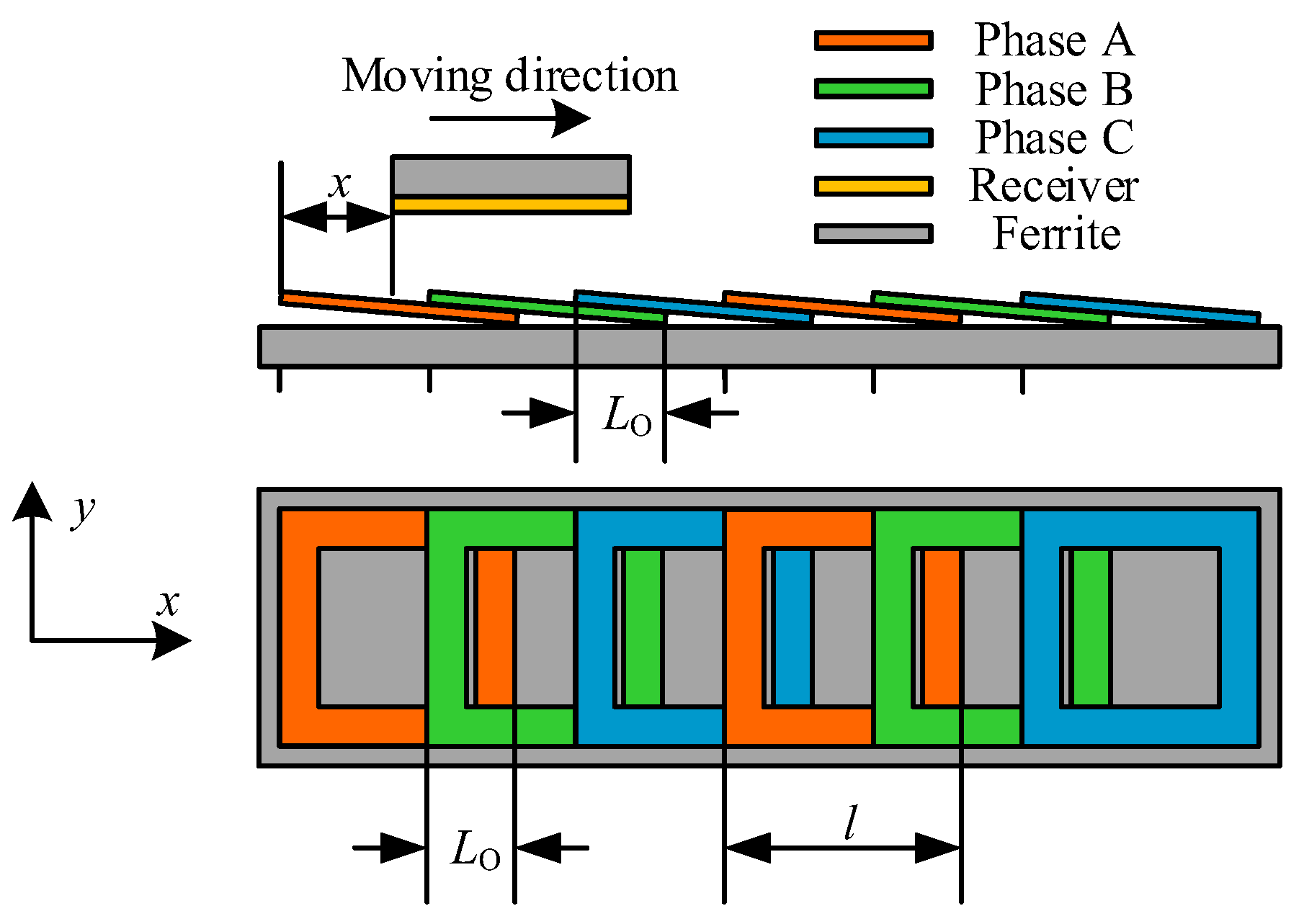
The coil structure of the dynamic charging system is depicted in Figure 1. Six square unipolar coils are arranged closely on the ferrite plates. The size of a single square coil is .
The equivalent circuit for the three-phase system is shown in Figure 2. The phasors of the induced voltages , and in the receiver can be expressed as:
where is the angular frequency of the system, and , and are the phasors of the current in transmitter A, B and C, respectively. Therefore, the sum of induced voltage on the receiver side is as follows:
The mutual inductance between the transmitter and receiver coils is calculated using a 3-D FEA tool, ANSYS Maxwell (Ozen Engineering, Inc., Silicon Valley, CA, USA). The specifications in simulation and experiment are listed in Table 1. is defined as the relative position between the transmitter and receiver. The simulated mutual inductance between the transmitter and receiver coils is shown in Figure 3.
Assuming that the amplitude of each coil current is equal. The relationship between , and can be expressed as:
where is the RMS value of the current in the transmitter coil. The amplitude of the induced voltage can be expressed as:
is the sum of all mutual inductances:
The Equation (4) shows that the amplitude of the induced voltage is related to directly, when and are constant.
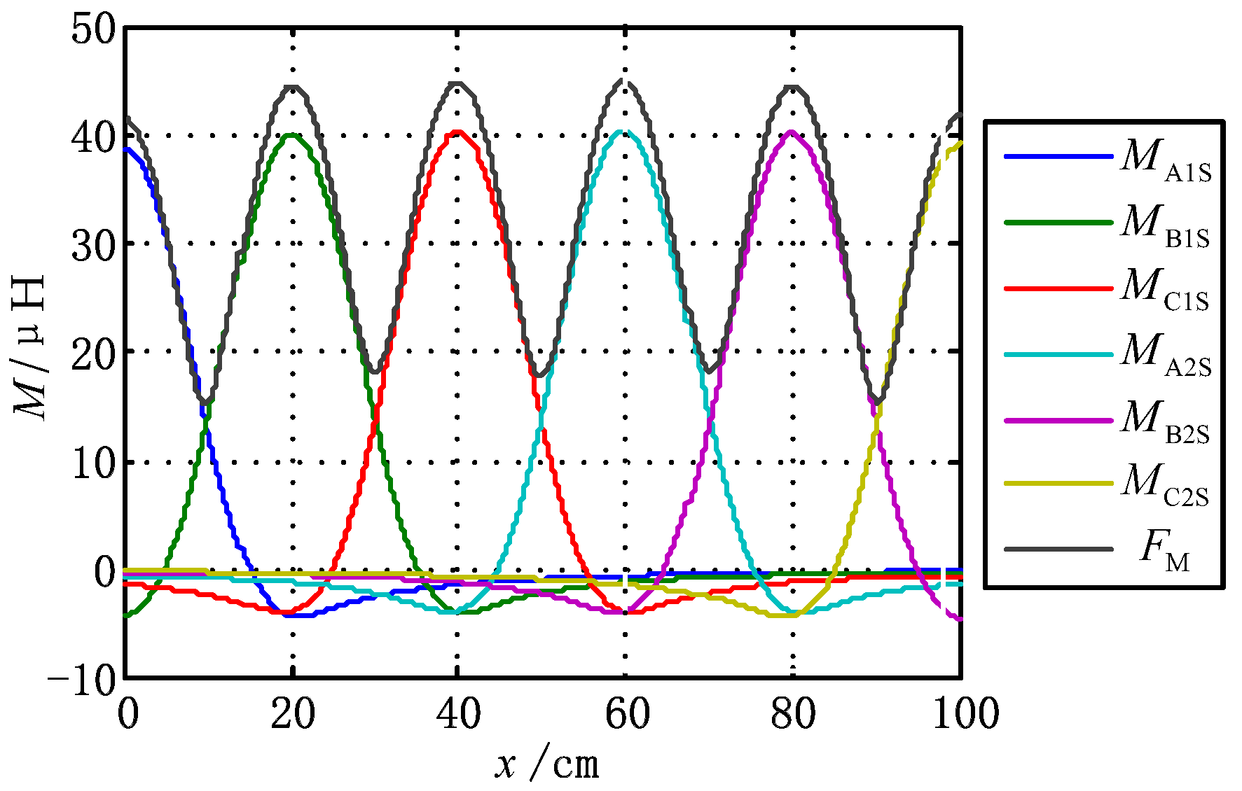
The mutual inductances against the location of the receiver and calculated by Equation (5) are shown in Figure 4. Large fluctuation of exists with the given parameters, which will lead to the fluctuation of the induced voltage. In order to alleviate the fluctuation of , overlapping is employed, which is depicted in Figure 5. The overlap length is defined as .
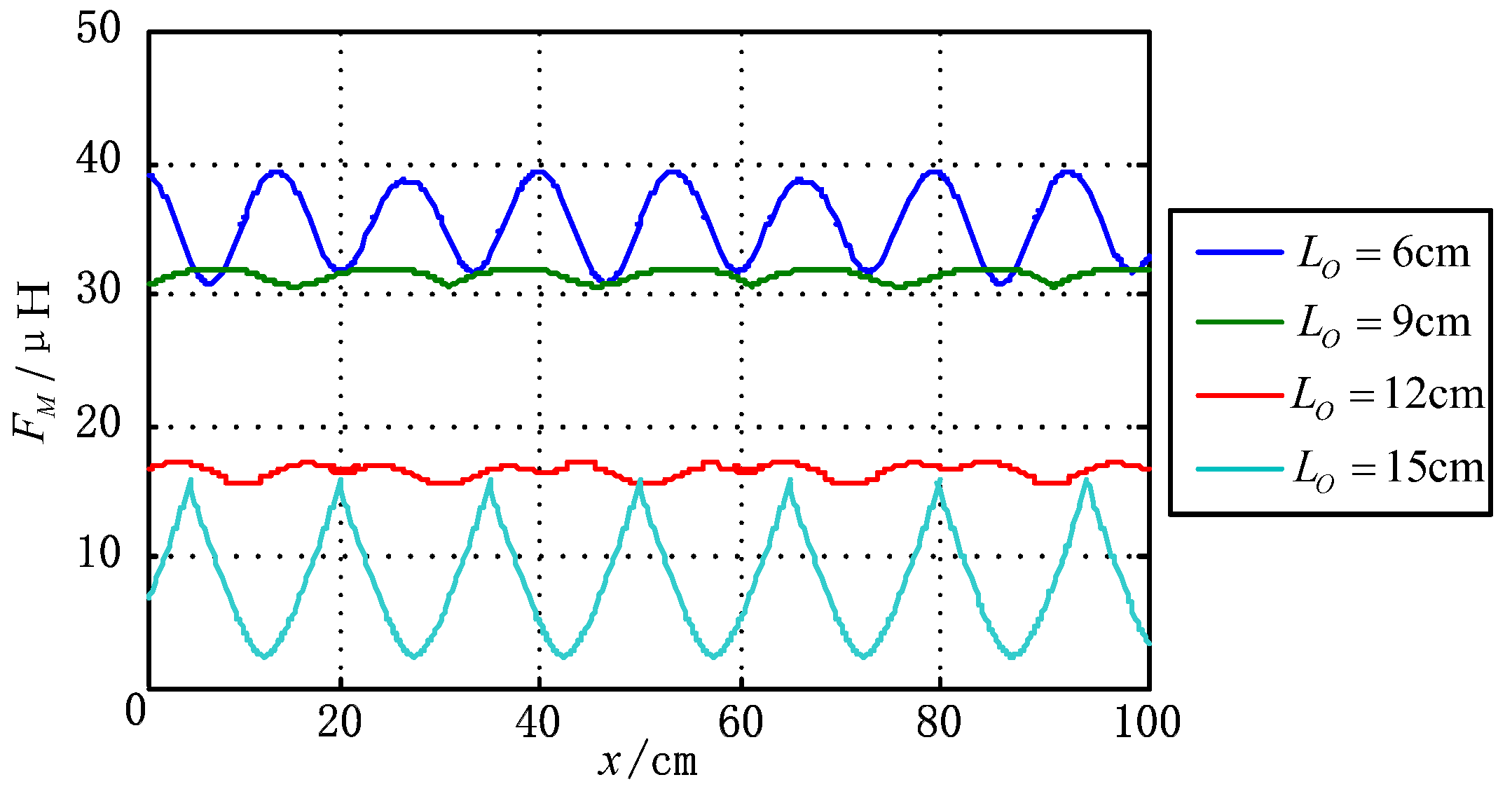
From the Figure 6, the fluctuation of varies as per the overlap of coils. It is of importance to find the optimal overlap length to minimize the fluctuation of . The variance is used to measure the fluctuation of , when the receiver moves from the second transmitter coils to the fifth transmitter coils. The variance of with various overlapped length is calculated and shown in Figure 7.
is the square of the standard deviation of . As shown in Figure 7, varies with the overlap proportion of the coil length, and the smallest variance occurs when is about 0.45. The calculated variance reaches the smallest value when the overlap proportion is 0.445 from the details of Figure 7. Meanwhile, the fluctuation of is the minimum, and the induced voltage is nearly uniform versus the variation of .
According to the analysis, the induced voltage is dependent on the sum of all mutual inductances. The fluctuation of and the voltage can be reduced by overlapping three-phase transmitter coils.
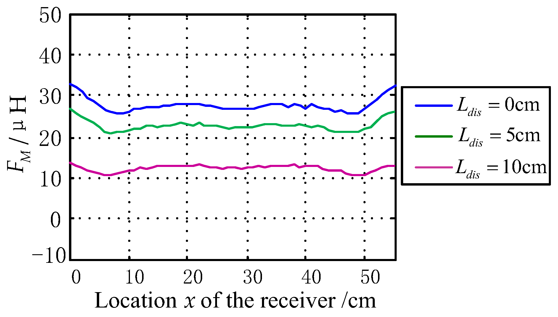
The fluctuation of is robust to the movement of the receiver along the x direction, but is affected by the misalignment between the transmitter coils and the receiver coil along the y direction as shown in Figure 5. Considering the misalignment along the y direction, the mutual inductances is simulated by ANSYS Maxwell, and is calculated. The calculated results are shown in Figure 8 where indicates the lateral displacement of the receiver along the y direction. The mutual inductances between the transmitters and the receiver will decrease with the increment of . The fluctuation of is still constant, but smaller than that with no misalignment, when the receiver moves along the track.
3. Circuit Analysis
The circuit topology of the dynamic WPT system is shown in Figure 9. The input of the system is a direct current (DC) source , which is connected to a three-phase full-bridge inverter to apply three high-frequency ac voltage , and to the resonant circuit. The LCC networks [24,25] are chosen as the resonant compensation topologies for the transmitters. Each transmitter coil is compensated independently. There are transmitter coil (, ), resonant compensation inductors (, ), and resonant capacitors (, ) and (, ) in each transmitter side. A series resonant compensation, consisting of and , is adopted on the receiver side. , and are the mutual inductances between the transmitter coils and receiver coil. , and are the mutual inductances between the transmitter coils.
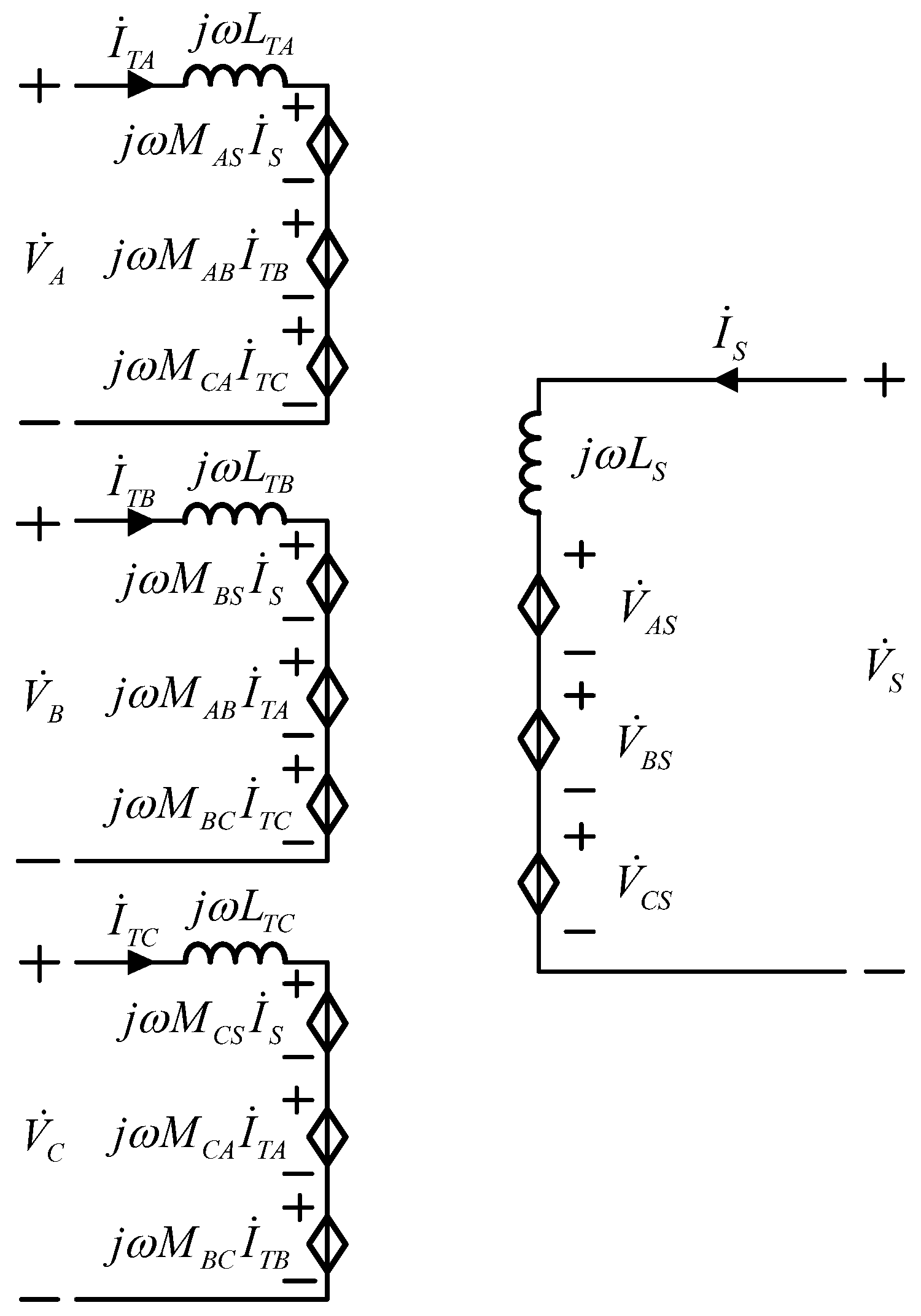
The fundamental harmonics approximation method is used to analyze the circuit shown in Figure 10. The inverter is regarded as first-order harmonic voltage sources. (, ) and are the equivalent series resistors of the transmitter coil A (B, C) and the receiver coil respectively. The rectifier and the dc load resistor can be represented as an equivalent AC load resistor [27], which is defined as:
(, ) and (, ) are the circuit impedance of the A (B, C)-phase in transmitter side. The circuit impedance of receiver side is which is defined as:
Each transmitter circuit parameters of the three-phase dynamic charging system are the same. Thus, the relationship is expressed as:
The values of , and are designed by:
Based on the Kirchhoff’s voltage law, the system can be expressed as:
The induced voltage in the receiver can be calculated from Equation (10) as:
where , and are the output voltages of the three-phase inverter. The relationship between , and can be shown as:
By substituting Equation (12) into Equation (11), the induced voltage can be derived as:
Considering Equations (5) and (13), the output voltage is related to , when the , and are constant. Consequently, the fluctuation of output voltages reaches the minimum value with minimal fluctuation of .
It should be noted that the angle frequency of the system is fixed and is equal to that of the inverter. Except for the generation of pulse width modulation (PWM) waves of the three-phase inverter, there’s no extra measurement circuit or control loop which is easy for implementation for practice.
4. Experimental Verification
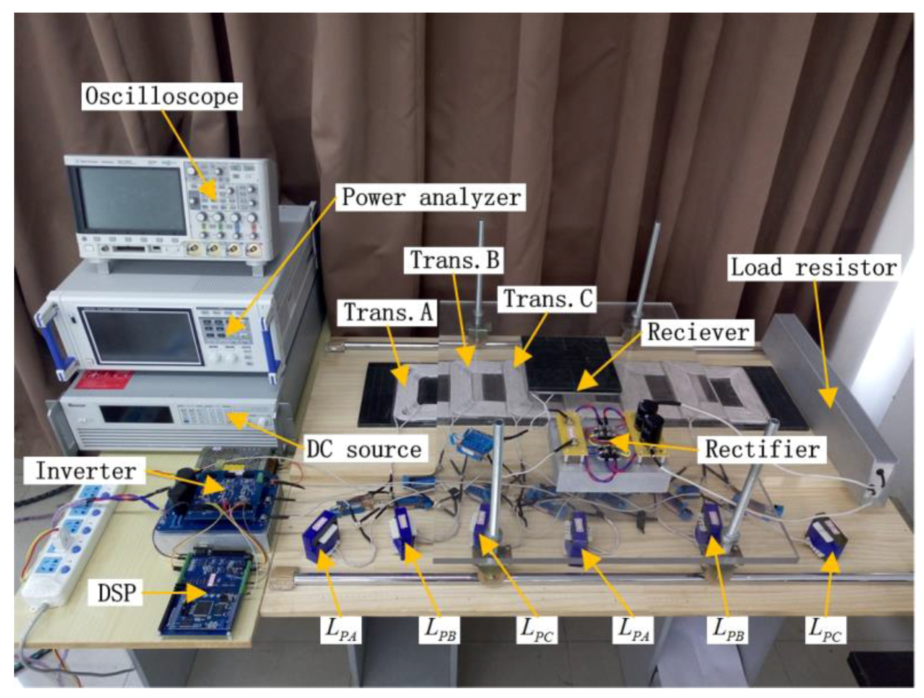
A 500 W system is established to validate the proposed dynamic charging system as shown in Figure 11. All of the six transmitter coils have the same shape. Each transmitter coil with its compensation circuit is connected with a three-phase inverter in parallel. A square coil works as a receiver. The size and shape of each coil is identical as that described in Section 2. Six transmitter coils share a three-phase inverter. The air gap distance in the dynamic charging system is 70 mm. The rectifier and the compensation circuit of receiver coil are connected to a dc load resistor. The circuit parameters of the experimental system are listed in Table 2.
A three-phase inverter is used to provide an ac excitation at the primary side. The oscilloscope Agilent DSO-X 3014T (Keysight Technologies, Beijing, China) is used to recording waveforms, and the efficiency between dc source and dc load is gauged by the power analyzer HIOKIPW6001 (HIOKI, Tokyo, Japan). When the receiver position mm, the stable waveforms of the output voltage of the three-phase inverter, the output current of the three-phase inverter, the input voltages and the input current of the rectifier are illustrated in Figure 12.
In Figure 13a, is aligned with transmitter coil . is much larger than and . Therefore, is much larger than the other two, where and are almost equal. As the receiver moves to the transmitter coil , the increases gradually and the is gradually reduced which is shown in Figure 13b,c.
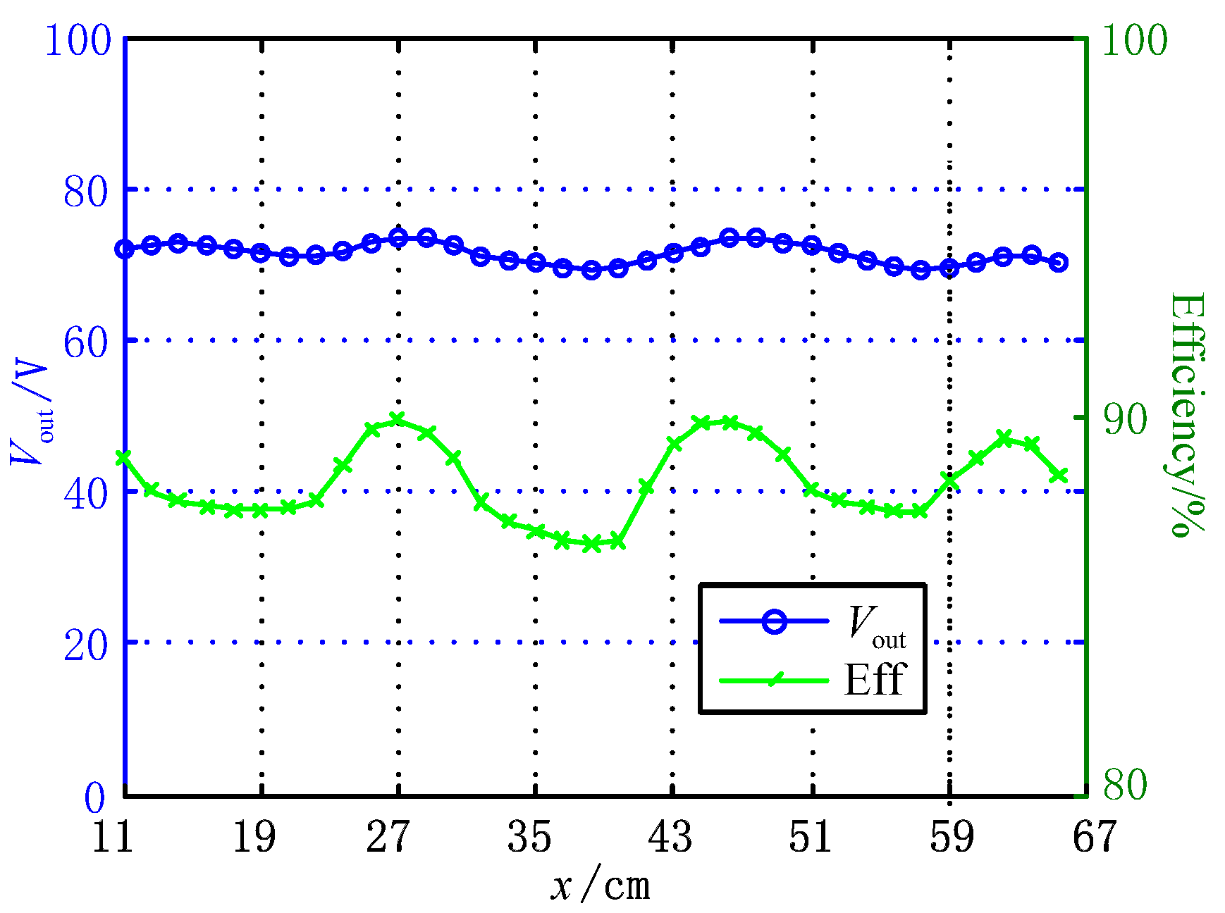
When the receiver moves along the transmitters track, the system output voltage and efficiency are shown in Figure 14. The system output voltage stays about 72 V with a fluctuation of ±3.05%. The highest system efficiency between the dc source and the dc load reaches up to 89.94% and the lowest efficiency is 86.67%. In [28], the system output power fluctuation is about ±5.89% with a load resistance of 50 Ω, and the maximum of the output power is 230 W. The verification system’s maximum output power is around 120 W in [29]. The maximum efficiency is 84% and the fluctuation of power is more than ±50%.
5. Conclusions
Aimed at reducing the voltage fluctuations in a dynamic WPT system, a three-phase dynamic charging system with two closely arranged overlapping transmitter coils to eliminate voltage dips between coils is proposed in this paper. The overlap length is optimized to reduce the fluctuation of the output voltage. The LCC-S compensation network is adopted in this paper. A 500 W output power dynamic charging system is set up to validate the proposed method. The experimental results show that the fluctuation of system output voltage is ±3.05%. The system’s highest efficiency from dc source to dc load reaches 89.94%.
Acknowledgments
This paper was supported by National Key R&D Program of China (2017YFB1201002), the National Natural Science Foundation of China under Grant (No. 51677155), the Sichuan Youth Science & Technology Foundation (No. 2016JQ0033), the Fundamental Research Funds for the Central Universities (No. 2682017QY01).
Author Contributions
Ruikun Mai and Ling Fu designed the methodology and wrote the manuscript. Hongchao Li and Yeran Liu conceived and designed the experiments. Hongchao Li and Kunzhuo Zhou implemented the experiments. All authors contributed to improving the quality of the manuscript.
Conflicts of Interest
The authors declare no conflict of interest.
References
- Yilmaz, M.; Krein, P.T. Review of Battery Charger Topologies, Charging Power Levels, and Infrastructure for Plug-in Electric and Hybrid Vehicles. IEEE Trans. Power Electron. 2013, 28, 2151–2169. [Google Scholar] [CrossRef]
- Li, Y.; Mai, R.; Lin, T.; Sun, H.; He, Z. A Novel WPT System Based on Dual Transmitters and Dual Receivers for High Power Applications: Analysis, Design and Implementation. Energies 2017, 10, 174. [Google Scholar] [CrossRef]
- Aditya, K.; Williamson, S. Linearization and Control of Series-Series Compensated Inductive Power Transfer System Based on Extended Describing Function Concept. Energies 2016, 9, 962. [Google Scholar] [CrossRef]
- Keeling, N.A.; Covic, G.A.; Boys, J.T. A Unity-Power-Factor IPT Pickup for High-Power Applications. IEEE Trans. Ind. Electron. 2010, 57, 744–751. [Google Scholar] [CrossRef]
- Qiang, H.; Huang, X.; Tan, L.; Ji, Q.; Zhao, J. Achieving Maximum Power Transfer of Inductively Coupled Wireless Power Transfer System Based on Dynamic Tuning Control. Sci. China Technol. Sci. 2012, 55, 1886–1893. [Google Scholar] [CrossRef]
- Xue, R.; Cheng, K.; Je, M. High-Efficiency Wireless Power Transfer for Biomedical Implants by Optimal Resonant Load Transformation. IEEE Trans. Circuits Syst. I Regul. Pap. 2013, 60, 867–874. [Google Scholar] [CrossRef]
- Wu, H.H.; Gilchrist, A.; Sealy, K.D.; Bronson, D. A High Efficiency 5 kW Inductive Charger for EVs Using Dual Side Control. IEEE Trans. Ind. Inform. 2012, 8, 585–595. [Google Scholar] [CrossRef]
- Deng, J.; Lu, F.; Li, W.; Ma, R.; Mi, C. Zvs Double-Side LCC Compensated Resonant Inverter with Magnetic Integration for Electric Vehicle Wireless Charger. In Proceedings of the 2015 IEEE Applied Power Electronics Conference and Exposition (APEC), Charlotte, NC, USA, 15–19 March 2015; pp. 1131–1136. [Google Scholar]
- Buchmann, I. Fast and Ultra-Fast Chargers, 2017. Fast and Ultra-Fast Chargers—Battery University. Available online: http://batteryuniversity.com/learn/article/ultra_fast_chargers (accessed on 6 November 2017).
- Levitan, D. For Electric Car Batteries, the Race for a Rapid Charge, 2012. For Electric Car Batteries, the Race for a Rapid Charge—Yale E360. Available online: http://e360.yale.edu/features/for_electric_car_batteries__the_race_for_a_rapid_charge (accessed on 6 November 2017).
- Lee, W.Y.; Huh, J.; Choi, S.Y.; Thai, X.V.; Kim, J.H.; Al-Ammar, E.A.; El-Kady, M.A.; Rim, C.T. Finite-Width Magnetic Mirror Models of Mono and Dual Coils for Wireless Electric Vehicles. IEEE Trans. Power Electron. 2013, 28, 1413–1428. [Google Scholar] [CrossRef]
- Ko, Y.D.; Jang, Y.J. The Optimal System Design of the Online Electric Vehicle Utilizing Wireless Power Transmission Technology. IEEE Trans. Intell. Transp. Syst. 2013, 14, 1255–1265. [Google Scholar] [CrossRef]
- Jang, Y.J.; Suh, E.S.; Kim, J.W. System Architecture and Mathematical Models of Electric Transit Bus System Utilizing Wireless Power Transfer Technology. IEEE Syst. J. 2016, 10, 495–506. [Google Scholar] [CrossRef]
- Huh, J.; Lee, S.W.; Lee, W.Y.; Cho, G.H.; Rim, C.T. Narrow-Width Inductive Power Transfer System for Online Electrical Vehicles. IEEE Trans. Power Electron. 2011, 26, 3666–3679. [Google Scholar] [CrossRef]
- Onar, O.C.; Miller, J.M.; Campbell, S.L.; Coomer, C.; White, C.P.; Seiber, L.E. A Novel Wireless Power Transfer for in-Motion EV/PHEV Charging. In Proceedings of the 2013 Twenty-Eighth Annual IEEE Applied Power Electronics Conference and Exposition (APEC), Long Beach, CA, USA, 17–21 March 2013; pp. 3073–3080. [Google Scholar]
- Miller, J.M.; Jones, P.T.; Li, J.; Onar, O.C. Ornl Experience and Challenges Facing Dynamic Wireless Power Charging of EV’s. IEEE Circuits Syst. Mag. 2015, 15, 40–53. [Google Scholar] [CrossRef]
- Lee, K.; Pantic, Z.; Lukic, S.M. Reflexive Field Containment in Dynamic Inductive Power Transfer Systems. IEEE Trans. Power Electron. 2014, 29, 4592–4602. [Google Scholar] [CrossRef]
- Zhao, J.; Cai, T.; Duan, S.; Feng, H.; Chen, C.; Zhang, X. A General Design Method of Primary Compensation Network for Dynamic WPT System Maintaining Stable Transmission Power. IEEE Trans. Power Electron. 2016, 31, 8343–8358. [Google Scholar] [CrossRef]
- Miller, J.M.; Onar, O.C.; White, C.; Campbell, S.; Coomer, C.; Seiber, L.; Sepe, R.; Steyerl, A. Demonstrating Dynamic Wireless Charging of an Electric Vehicle: The Benefit of Electrochemical Capacitor Smoothing. IEEE Power Electron. Mag. 2014, 1, 12–24. [Google Scholar] [CrossRef]
- Covic, G.A.; Boys, J.T.; Kissin, M.L.G.; Lu, H.G. A Three-Phase Inductive Power Transfer System for Roadway-Powered Vehicles. IEEE Trans. Ind. Electron. 2007, 54, 3370–3378. [Google Scholar] [CrossRef]
- Pacini, A.; Mastri, F.; Trevisan, R.; Masotti, D.; Costanzo, A. Geometry Optimization of Sliding Inductive Links for Position-Independent Wireless Power Transfer. In Proceedings of the 2016 IEEE MTT-S International Microwave Symposium (IMS), San Francisco, CA, USA, 22–27 May 2016; pp. 1–4. [Google Scholar]
- Mou, X.; Groling, O.; Sun, H. Energy-Efficient and Adaptive Design for Wireless Power Transfer in Electric Vehicles. IEEE Trans. Ind. Electron. 2017, 64, 7250–7260. [Google Scholar] [CrossRef]
- Zhang, Z.; Chau, K.T. Homogeneous Wireless Power Transfer for Move-and-Charge. IEEE Trans. Power Electron. 2015, 30, 6213–6220. [Google Scholar] [CrossRef]
- Zhu, Q.; Wang, L.; Guo, Y.; Liao, C.; Li, F. Applying LCC Compensation Network to Dynamic Wireless EV Charging System. IEEE Trans. Ind. Electron. 2016, 63, 6557–6567. [Google Scholar] [CrossRef]
- Lu, F.; Zhang, H.; Hofmann, H.; Mi, C.C. A Dynamic Charging System with Reduced Output Power Pulsation for Electric Vehicles. IEEE Trans. Ind. Electron. 2016, 63, 6580–6590. [Google Scholar] [CrossRef]
- Boys, J.T.; Covic, G.A. The Inductive Power Transfer Story at the University of Auckland. IEEE Circuits Syst. Mag. 2015, 15, 6–27. [Google Scholar] [CrossRef]
- Erickson, R.W.; Maksimovic, D. Fundamentals of Power Electronics; Springer: Berlin, Germany, 2001. [Google Scholar]
- Park, C.; Lee, S.; Jeong, S.Y.; Cho, G.; Rim, C.T. Uniform Power I-Type Inductive Power Transfer System with DQ-Power Supply Rails for On-Line Electric Vehicles. IEEE Trans. Ind. Electron. 2015, 30, 6446–6455. [Google Scholar] [CrossRef]
- Zhou, S.; Chris Mi, C. Multi-Paralleled LCC Reactive Power Compensation Networks and their Tuning Method for Electric Vehicle Dynamic Wireless Charging. IEEE Trans. Ind. Electron. 2016, 63, 6546–6556. [Google Scholar] [CrossRef]
Figure 1.
Structure of the transmitters and receiver.
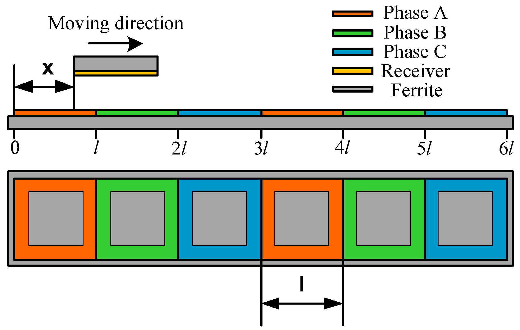
Figure 2.
Circuit topology of the proposed coil structure.

Figure 3.
Simulated mutual inductance between the receiver and transmitters.
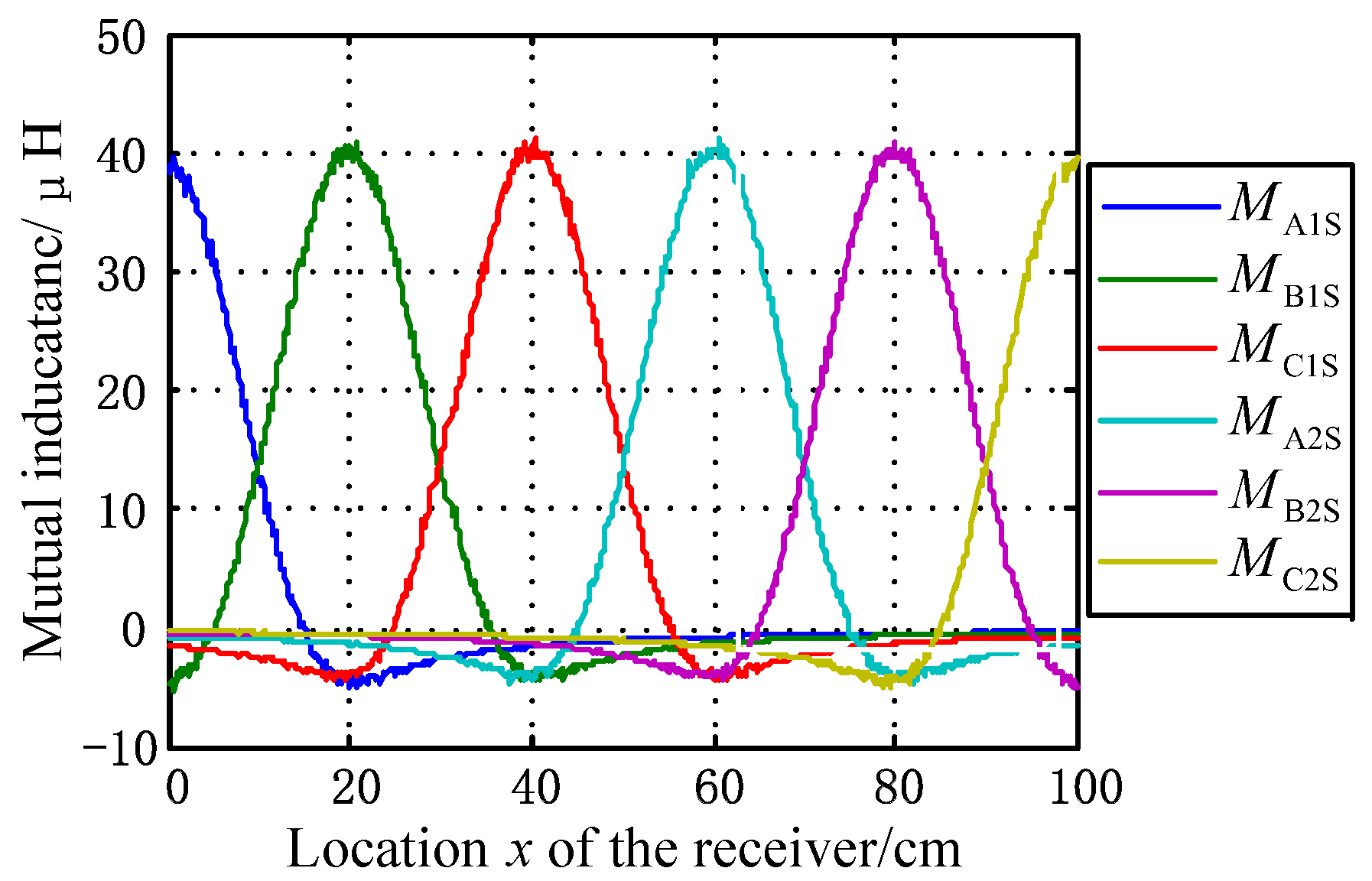
Figure 4.
Processed mutual inductance.

Figure 5.
Illustration of the transmitters and receiver after overlapping.

Figure 6.
The sum of mutual inductance with different overlapped length.

Figure 7.
Variance with various overlap proportion.
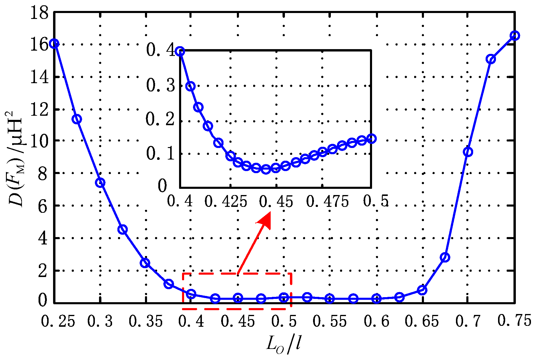
Figure 8.
The sum of mutual inductance considering misalignment along the y direction.

Figure 9.
Schematic of the proposed system.
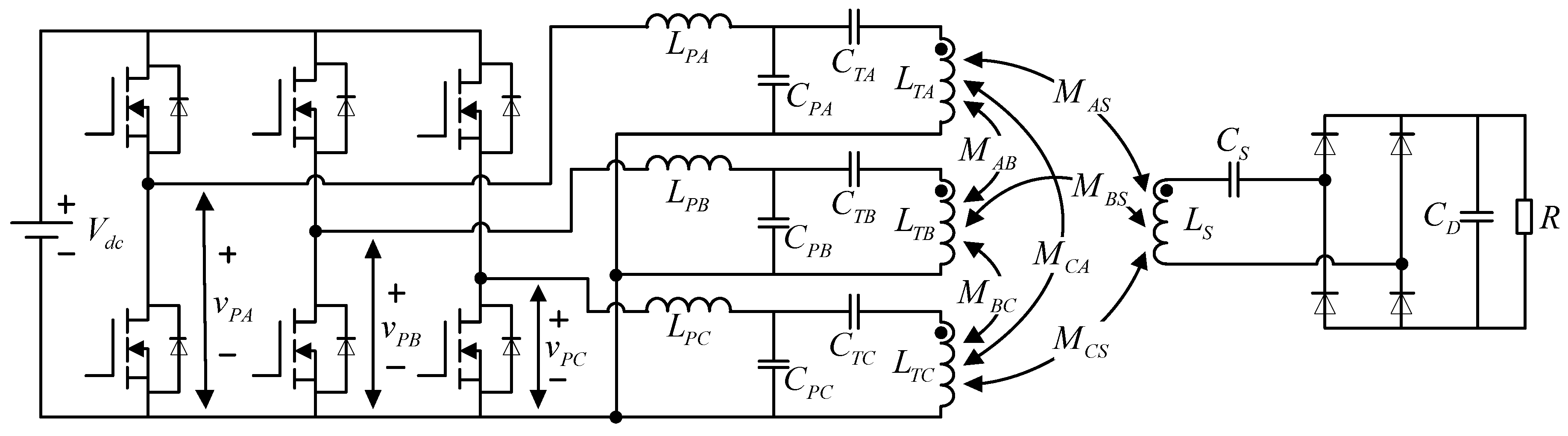
Figure 10.
Equivalent circuit of the proposed system.
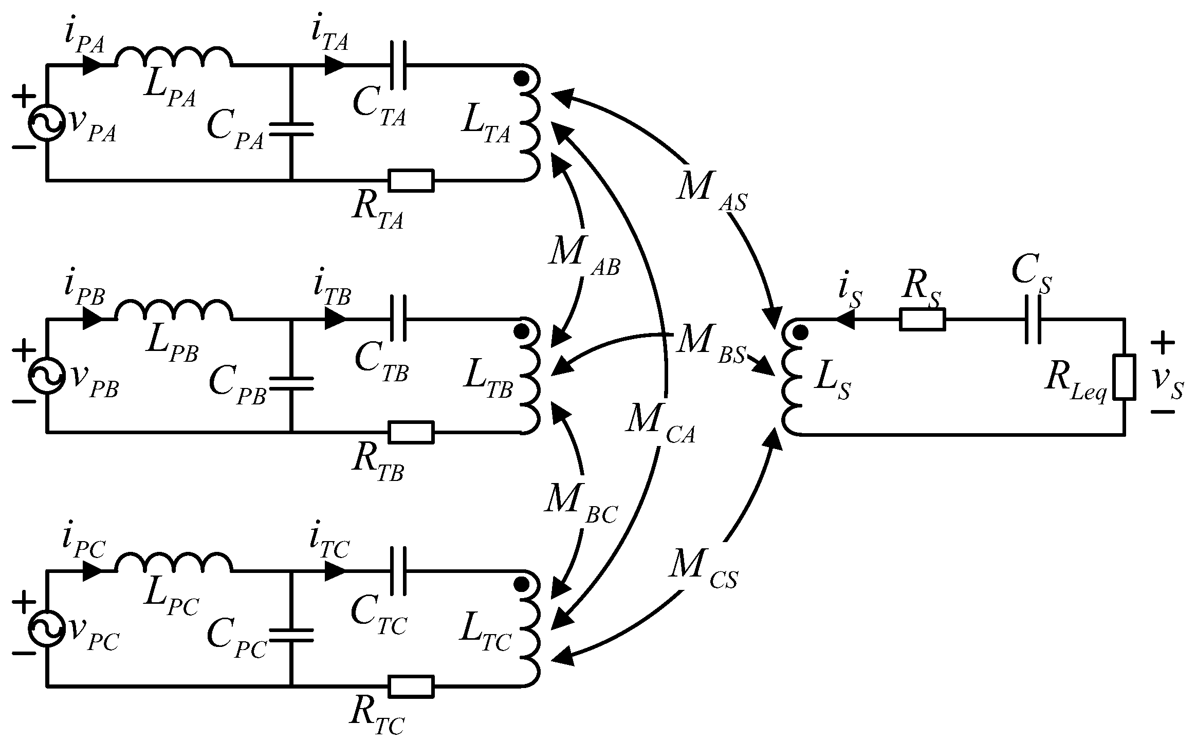
Figure 11.
Experimental prototype.

Figure 12.
Stable waveforms of the output voltages and currents of inverter and rectifier.
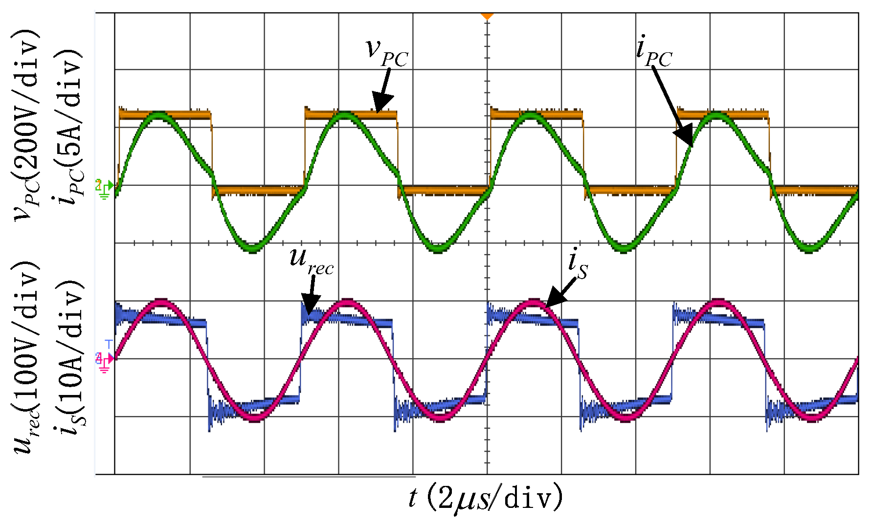
Figure 13.
Measured the input current of inverter waveforms. (a) Waveforms with ; (b) waveforms with ; (c) waveforms with .
Figure 13.
Measured the input current of inverter waveforms. (a) Waveforms with ; (b) waveforms with ; (c) waveforms with .
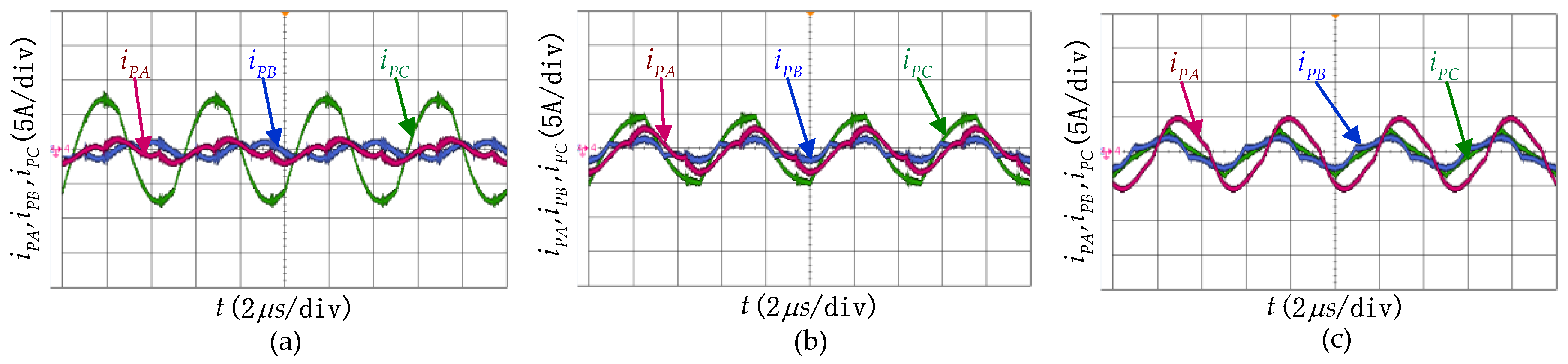
Figure 14.
System output voltage and efficiency with various receiver positions.


Table 1.
Parameters of the transmitter and the receiver.
| Parameters | Value |
|---|---|
| Length of a Q coil [26] /mm | 200 |
| Air gap distance /mm | 70 |
| Q coil turns in transmitter A | 17 |
| Q coil turns in transmitter B | 17 |
| Q coil turns in transmitter C | 17 |
| Q coil turns in receiver | 17 |
| Relative position /mm | [0,1200] |
Table 2.
Parameters of the experiment system.
| Parameters | Value | Parameters | Value |
|---|---|---|---|
| /kHz | 200 | /Ω | 0.15 |
| /V | 315 | /μH | 50.29 |
| /V | 72 | /nF | 12.94 |
| /cm | 8.9 | /μH | 119.47 |
| /μH | 50.39 | /nF | 15.32 |
| /nF | 12.36 | /Ω | 0.1 |
| /μH | 120.1 | /μH | 110.53 |
| /nF | 14.98 | /nF | 5.96 |
| /Ω | 0.1 | /Ω | 0.18 |
| /μH | 49.6 | Maximum value of /μH | 37.68 |
| /nF | 13.73 | Maximum value of /μH | 38.1 |
| /μH | 122.8 | Maximum value of /μH | 38.55 |
| /nF | 13.95 | Output capacitor /μF | 940 |
© 2018 by the authors. Licensee MDPI, Basel, Switzerland. This article is an open access article distributed under the terms and conditions of the Creative Commons Attribution (CC BY) license (http://creativecommons.org/licenses/by/4.0/).
Share and Cite
MDPI and ACS Style
Mai, R.; Li, H.; Liu, Y.; Zhou, K.; Fu, L.; He, Z. A Three-Phase Dynamic Wireless Charging System with Constant Output Voltage. Energies 2018, 11, 45. https://doi.org/10.3390/en11010045
AMA Style
Mai R, Li H, Liu Y, Zhou K, Fu L, He Z. A Three-Phase Dynamic Wireless Charging System with Constant Output Voltage. Energies. 2018; 11(1):45. https://doi.org/10.3390/en11010045
Chicago/Turabian StyleMai, Ruikun, Hongchao Li, Yeran Liu, Kunzhuo Zhou, Ling Fu, and Zhengyou He. 2018. "A Three-Phase Dynamic Wireless Charging System with Constant Output Voltage" Energies 11, no. 1: 45. https://doi.org/10.3390/en11010045
Note that from the first issue of 2016, this journal uses article numbers instead of page numbers. See further details here.