Output Power Smoothing and Voltage Regulation of a Fixed Speed Wind Generator in the Partial Load Region Using STATCOM and a Pitch Angle Controller


Department of Electrical Engineering, Indian Institute of Technology Roorkee, Roorkee 247667, India
*
Author to whom correspondence should be addressed.
Energies 2018, 11(1), 58; https://doi.org/10.3390/en11010058
Submission received: 30 October 2017
/
Revised: 15 December 2017
/
Accepted: 25 December 2017
/
Published: 29 December 2017
(This article belongs to the Special Issue Wind Generators Modelling and Control)
Abstract
:The output power and terminal voltage of the fixed speed induction generator fluctuate in the partial load region where the wind speed is below the rated vale, resulting in fluctuations in the grid frequency and voltage. In this paper, a novel pitch angle control strategy has developed by introducing an exponential moving average (EMA) concept from which the controller reference power (signal) can be set for below-rated wind speeds. Therefore, the employed pitch angle controller together with static synchronous compensator (STATCOM), named the unified voltage and pitch angle controller (UVPC), addresses the objective of smoothing the output power and terminal voltage regulation of a wind generator, subjected to below-rated wind speed variations. Moreover, an interval type-2 fuzzy logic technique has incorporated in the pitch angle controller design, since it is more efficient in handling the uncertainties in membership functions and rules than its traditional fuzzy logic counterparts. Simulation results clearly show that the proposed UVPC effectively smoothens out the generator output power and also regulates the terminal voltage at its constant magnitude.
1. Introduction
Wind energy systems (WESs) are renewable energy sources that, at present, are enjoying drastic growth due to economical and environmental considerations. Today, more than 341,320 wind turbines are operating all over the world [1]. The different types of induction generator-based wind energy systems have been studied [2,3].
Nowadays modern wind energy systems mostly utilize variable-speed induction generators (doubly-fed) [4] but fixed-speed induction generators (FSIGs) are also still being used due to their low cost, low maintenance and robustness. For example, in Australia, Germany and Denmark respectively, about 87 MW, 48 MW and 47.1 MW of installed wind turbines (rated at 1.5 MW) are FSIG-based wind turbines [5]. Although fixed speed wind energy systems exist around the world in considerable number due to their own merits, they require dynamic reactive power support.
One of the concerns with fixed speed generators is wind speed variation. The output power of wind generators fluctuate as the wind speed varies (the output of a wind turbine is proportional to the cube of the wind speed). Moreover, the reactive power absorption by the induction generator is coupled to the active power generation resulting in any variation of wind speed also causing fluctuations in the reactive power of the generator. These fluctuating active and reactive powers interact with the power network and lead to fluctuations in the grid voltage and frequency [6].
The voltage regulation can be done by controlling the reactive power at the wind turbine generator. In this approach, dynamic reactive power compensation devices such as static var compensators (SVCs) have been employed [7]. However, compared to SVC the static synchronous compensator (STATCOM) provides faster and smoother dynamic voltage control because it exhibits a quick response time (1–2 cycles) [8]. The main purpose of STATCOM connected at the wind farms is to improve the transient stability as well as provide fault ride-through capability. In addition, it is well suited for voltage fluctuation reduction at the generator terminal due to wind speed variations that results in voltage flicker mitigation at the wind farm connection point. In this regard, a lot of research work on STATCOM with wind energy systems has been reported [9,10,11,12,13,14,15].
The classical STATCOM only operated in lagging and leading mode. Therefore, its role in the wind power system was limited to reactive power support. As a result, the wind generator output power fluctuations due to wind speed variations cannot be smoothened out by employing STATCOM, since it does not have an active power control capability. Thus, the STATCOM adopted with energy storage system (ESS) is one solution to control both active and reactive power as reported in the literature [16,17,18,19,20]. Energy storage systems (ESSs) have their own demerits. For example, battery energy storage systems (BESSs) have issues like a chemical process basis, short life spans and slow response. Superconducting magnetic energy storage (SMES) demands a huge initial installation cost and its application is still critical from a practical point-of-view. On the other hand, STATCOM with the pitch-angle controller is the best choice for controlling the active and reactive power of a wind energy system (WES).
Therefore, recent studies employed a simultaneous control of STATCOM (reactive power control) and pitch angle control (active power control) to enhance the wind farm low voltage ride- through capability when subjected to network faults [21,22]. The idea of mixing electrical and mechanical parts seems to be interesting but it has not been explored in respect of wind speed variations, due to which the output power and voltage of the wind generator fluctuate. This is becoming more concerning as the wind generator installations are increasing in number. Motivated by [21,22], this paper contributes to smoothing the output power fluctuations and voltage regulation of the fixed speed wind generator, subjected to below-rated wind speed variations using STATCOM and a pitch angle controller.
In general, a pitch angle controller limits the aerodynamic power at its rated level irrespective of wind speed variations when the wind speed exceeds the rated speed, but at below-rated wind speed (i.e., in the partial load region), there the pitch angle control system has no role in controlling the active power (in this region the maximum power extraction is allowed). As a result, any variation in the wind speed causes fluctuations in output power. Therefore, recently different pitch angle controller schemes were employed for smoothing the generator output power fluctuations subjected to below-rated wind speed variations [23,24,25].
Another contribution of this paper, the fuzzy logic controller (FLC) employed for below-rated wind speed in [25], is best suited as it provides improved performance in tracking reference, simple structure and is easily implemented as compared to other control techniques. However, once the membership functions have been defined for designing the controller, the uncertainties in actual degree of membership functions (MFs) cannot be modeled [26]. This may degrade the controller performance, especially when the plant is subjected to disturbances. Therefore, an advanced fuzzy logic (interval Type-2 FLC) was developed which deals with the issues of uncertainty in MFs and fuzzy rules [27,28]. Thus, an attempt has been made to design the pitch angle controller using an interval type-2 FLC.
Therefore, the novelty of this paper lies in providing a method for smoothening out the output power fluctuations and terminal voltage regulation of the fixed speed wind generator, subjected to below-rated wind speed variations by employing a type-2 FLC based typical pitch controller (specially designed for below rated wind speeds) and STATCOM. We name this approach the UVPC strategy.
2. Configuration of the System
To evaluate the proposed UVPC control strategy the typical power system considered in this study is as shown in Figure 1. The stator winding of the generator is connected to the point of common coupling (PCC) through a step-up transformer (0.69/25 kV) which exports power to the 120 kV grid through a transmission line. Each induction generator (IG) works at the rated operating point and supplies 1.5 MW of active power. The considered wind farm in this study consists of twenty-four 1.5 MW rated fixed speed wind turbines and thus a 36 MW wind farm has been connected to the 120 kV grid. The power factor correction capacitor (C) is connected to the low voltage terminal of each wind turbine generator. Under steady-state conditions, the capacitors provide the required amount of reactive power to the FSIGs, but they fail to supply the dynamic reactive power demanded by the FSIGs under disturbances conditions. To supply the reactive power and maintain the voltage regulation at the PCC under disturbances such as wind speed and faults, a STATCOM has been employed and connected to the 25 kV bus. The design parameters of the generator and wind turbine are presented in Appendix A.
The addition of STATCOM with pitch angle control is expected to control the voltage and output power of wind farm subjected to wind speed disturbances. Therefore, in this paper the UVPC strategy is proposed to control both the mechanical torque (resulting in active power control) and reactive power (resulting in voltage control), by employing a pitch angle controller and STATCOM, respectively.
2.1. Aerodynamic Conversion of Wind Turbine
The mechanical power developed by the rotor of the wind turbine is directly proportional to the cube of wind speed as:
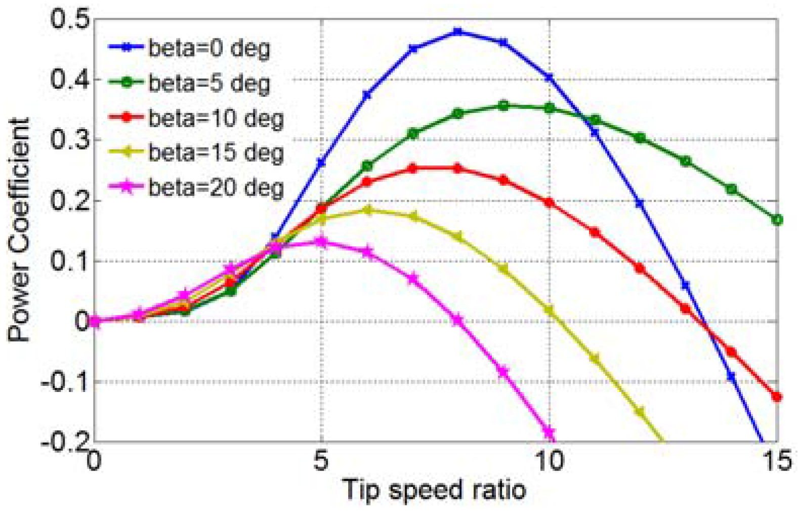
where, Vw (m/s) is the wind speed, ρ (kg/m3) is the air density, Ar = πR2 (m2) is the rotor swept area, R (m) is the radius of the blade, and is the power coefficient which depends upon the ratio of rotor-tip speed () and blade pitch-angle (). For commercial wind turbines, manufacturers generally not provide any information about the power coefficient, therefore, several mathematical approximations have been developed to determine this value. Many references have described the power coefficient curve with different appropriate equations. In this work, the power coefficient () characteristic is determined as follows [29]:
where:
The coefficients c6–c1 are: c6 = 0.0068, c5 = 21, c4 = 5, c3 = 0.4, c2 = 116 and c1 = 0.5176 and the blade tip-speed ration () can be defined as:
where, ω (rad/s) is the turbine shaft angular speed. Utilizing Equations (1)–(4), the power coefficient versus tip-speed ratio (Cp − λ) curve for different values of the pitch-angle (β) is obtained as shown in Figure 2. The maximum power can be extracted if the power coefficient (Cp) is kept at maximum power coefficient (Cpmax), which is obtained with the optimal values of the pitch-angle β and the tip-speed ratio λ i.e.,
In this paper, the maximum value of Cpmax reaches 0.48, with λopt = 8.1 and βopt = 0° as shown in Figure 2.
2.2. Modeling of Induction Generator
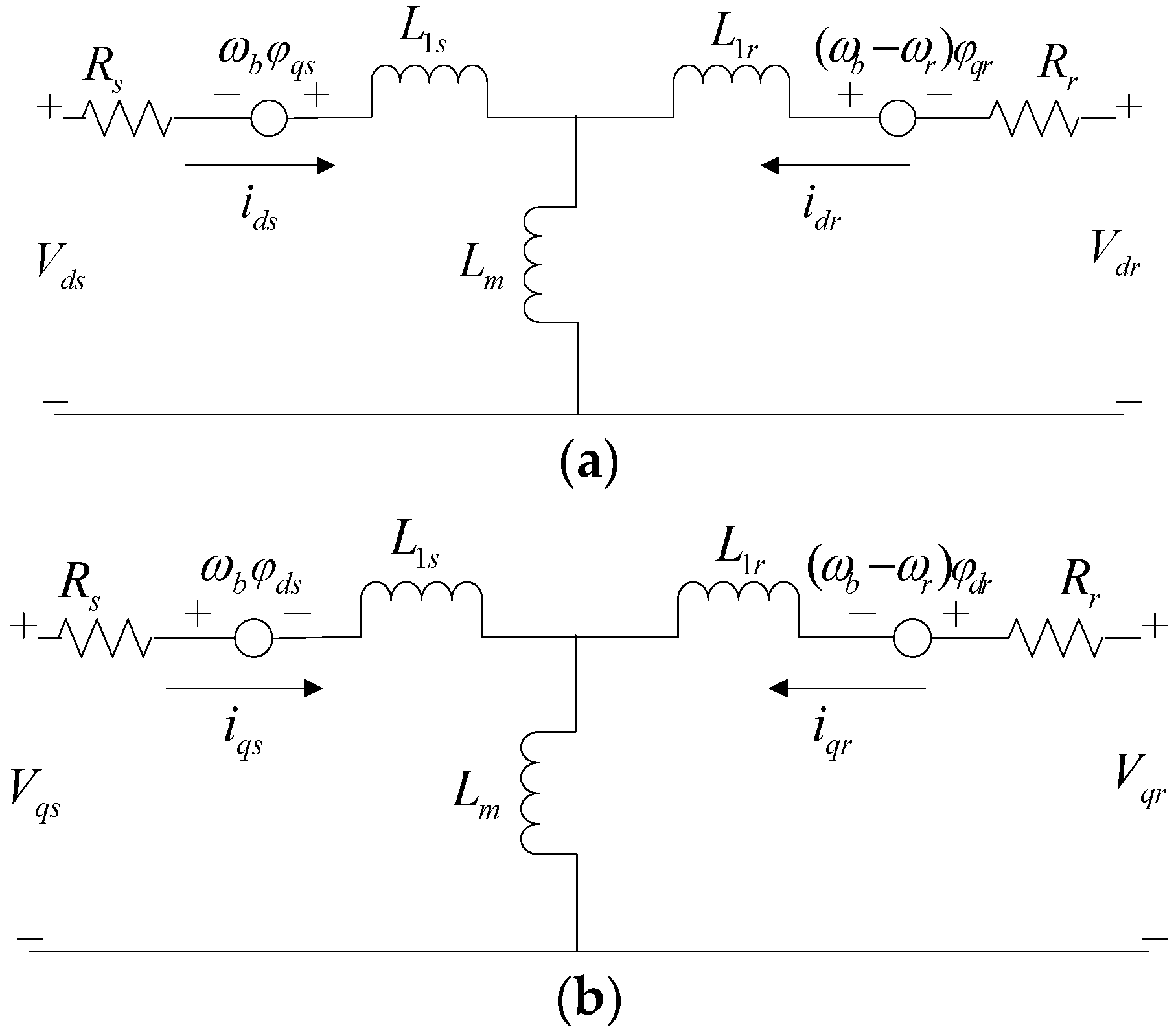
For the modeling of induction generator (IG), the a-b-c reference frame is transformed into the d-q axis reference frame and the equivalent model is as shown in Figure 3 [29].
All electrical variables and parameters are referred to the stator, where φds, φqs, φdr, φqr, Vds, Vqs, Vdr, Vqr and ids, iqs, idr, iqr are the flux linkages, voltages and currents of the stator and rotor in d-q reference frame, respectively.
L1s and L1r are the stator and rotor leakage inductances, ωb is the base speed of the reference and ωr is the generator rotor speed, Ls, Lr and Lm, are the stator, rotor and mutual inductances, respectively. Moreover, Rs and Rr are the stator and rotor resistances.
The per-unit equation of the electromagnetic torque is expressed as:
Since, the wind turbine and generator rotor can be modelled as single mass system, the dynamic equation of motion can be written as:
where, H represents the induction generator rotor and wind turbine equivalent inertia constant.
3. The Employed STATCOM Control Scheme
The well-known STATCOM model employed is shown in Figure 4, which includes a power electronic voltage source converter (VSC), coupling transformer and control system. The AC line voltage (V) is compared with the reference voltage (Vref). The error/deviation in line voltages (ΔV) is processed through the controller PIAC. For an AC voltage control loop the controller (PIAC) output () determines the amount of reactive power to be generated by STATCOM. In order to support the STATCOM DC bus, DC bus voltage (Vdc) is compared with the reference DC voltage (Vdcref) and the error voltage (ΔVDC) is passed through another controller (PIDC). The output () of this controller determines the source current active power component. The voltage regulation controller (PIAC), which reacts to a sudden voltage variation and injects the appropriate amount of reactive power, is therefore well adapted for system disturbances such as faults and wind speeds above and below the rated wind speed. A detailed STATCOM control scheme is available [30].
The AC voltage error (ΔV) at the n-th instant is:
where, V(n) is the magnitude of the sensed three phase voltages at the PCC at the n-th instant, Vref is the amplitude of the reference voltage.
The AC voltage controller (PIAC) output () at the n-th sampling to regulate the PCC voltage can be expressed as:
where, KPac and KIac are the proportional and integral gain constants of the AC voltage controller, ΔV(n) and ΔV(n−1) are the error voltages at the n-th and (n − 1)-th instant and () is the quadrature components of the reference current at the (n − 1)-th instant.
Similarly, the DC bus voltage error (ΔVDC) at the n-th sampling is:
where, Vdc(n) is the sensed DC link voltage of the STATCOM at the n-th instant and Vdcref is the reference DC voltage. The output of the PIDC controller is to support the STATCOM DC voltage at the n-th sampling and expressed as:
where and are the active power components of the source current at the n-th and (n − 1)-th instant. KPdc and KIdc are the proportional and integral gain constants of the DC voltage controller. Two PI controllers gains (KPac = 4.6, KIac = 50, KPac = 0.01 and KIac = 0.2) of the STATCOM are obtained at a specific operating point in order to achieve satisfactory performance when the system is subjected to small and large disturbances.
4. Pitch Angle Controller Design for Below-Rated Wind Speeds
In the case of above rated wind speed (full load region), the pitch angle controller is employed to regulate the output power at its rated value by generating a suitable pitch angle, but at below-rated wind speeds (in the partial load region), the pitch angle controller plays no role and extracts the maximum amount of output power according to wind speed variations. As a result, any variation in the wind speed causes high fluctuations in the output power.
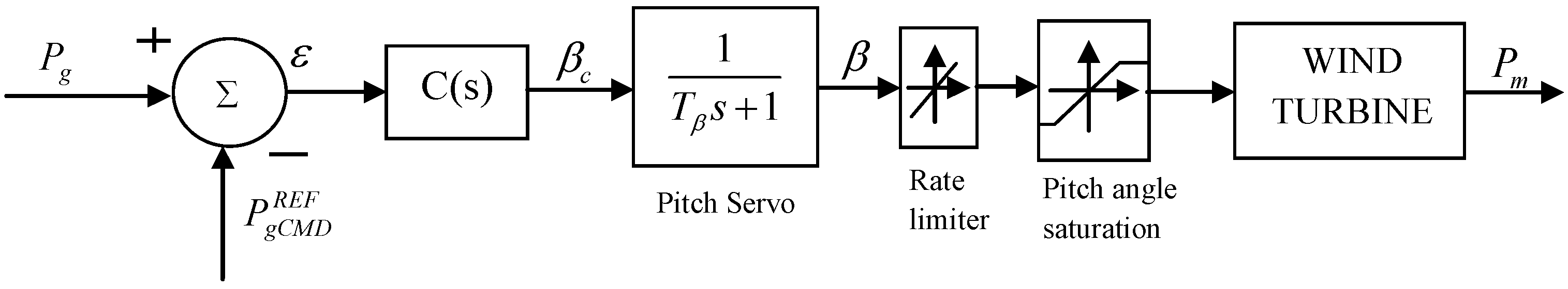
This study develops a novel type pitch angle controller for below-rated wind speeds, with which the generator output power can be smoothened out by generating an appropriate pitch angle. The major problem with this type of pitch angle controller is setting a reference power. The constant rated reference power setting is not a good choice since in this region the generator output power is less than the rated power. Therefore, in this paper an exponential moving average (EMA) concept has been introduced to generate a reference power () and thus a smoothed generator output power can be obtained. The employed pitch angle controller is as shown in Figure 5.
The difference between the measured output power (Pg) and reference power command () goes through the controller C(s), which regulates the output power in accordance with error (ε). The optimum pitch angle βC from the controller C(s) is used as reference for the pitch actuator/servo system. The purpose of the servo system is for proper orientation of the blades. By taking the blades’ direction into account the first order transfer function of the electric or hydraulic pitch servo is developed and given by:
The blade angle β follows the reference pitch or optimum pitch βC by a first order lag with time constant Tβ, which depends on the pitch actuator. In order to get a realistic response from the pitch control system, the pitch rate and the regulation range of pitch angle are set to ±2°/s and 0–45°, respectively.
Computing Controller Reference Power Command ()
In order to control the active power of the wind generator under below-rated wind speed conditions, an essential task is to calculate the reference power command (). Different approaches such as exponential moving average (EMA) and simple moving average (SMA) can be employed to determine the input power command [31]. However, in this paper the EMA concept has been incorporated since it exhibits a smoother and faster response than SMA.
The numerical expression for EMA is given as:
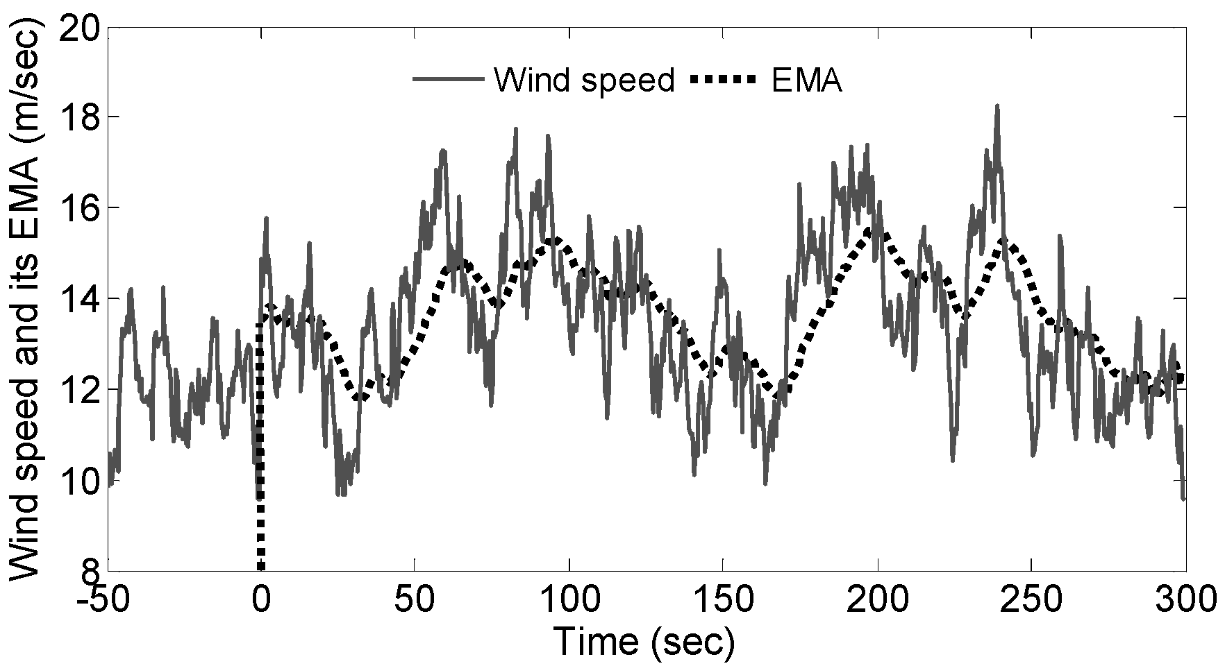
where, C represents the current value, and the preceding period of EMA is P, and K denotes a weighting factor. For period-based EMA, the weighting factor (K) is equal to 2/(1 + N), where N is the number of periods. A detailed explanation is presented in [31]. For example, for 50 periods the EMA weighting factor is calculated as: 2/(1 + 50) = 0.0196. Figure 6 demonstrates the average EMA values calculated for a given wind speed. It can be observed that the EMA starts from 50 s (each of 1 period) onwards. However, in this paper, the average EMA values are calculated for generated wind power (not for wind speed).
The input reference power command () for the pitch angle controller is calculated as follows:
- Step 1:
- The wind turbine capture power (PWT) can be obtained from Equation (1).
- Step 2:
- The average EMA value () of captured wind turbine power (PWT) is calculated from Equation (13). In this paper, 50 periods of average value are used in the simulation. Therefore, for every 50 s the EMA of the wind power computation has done. The EMA calculation as: for e.g., if the generated wind power is equal to 0.82 MW at 50th period and 0.81 MW at 51st period, respectively then the value of EMA at the time 51 s becomes [(0.81 − 0.82) × 0.0196] + 0.82 = 0.819 MW. If wind power generated becomes 0.8 MW at 52nd period, then the value of EMA at this instant calculated as [(0.8 − 0.819) × 0.0196] + 0.8 = 0.799 MW and so on.
- Step 3:
- The standard deviation can be calculated as:
- Step 4:
- Finally, the input command power of controller can be obtained as:
Figure 7 explains the whole calculation process of input power command.
5. The Proposed Unified Voltage and Pitch Angle Control (UVPC) Strategy
A reactive power compensator like STATCOM installed at the wind farm connection point can supply the amount of reactive power to the wind generator results in voltage regulation subjected to above/below rated wind speed disturbances. In the same trend, the novel pitch angle controller which is discussed in Section 4 can control the mechanical torque of the generator and thus can smooth the generator output power under below-rated wind speed conditions.
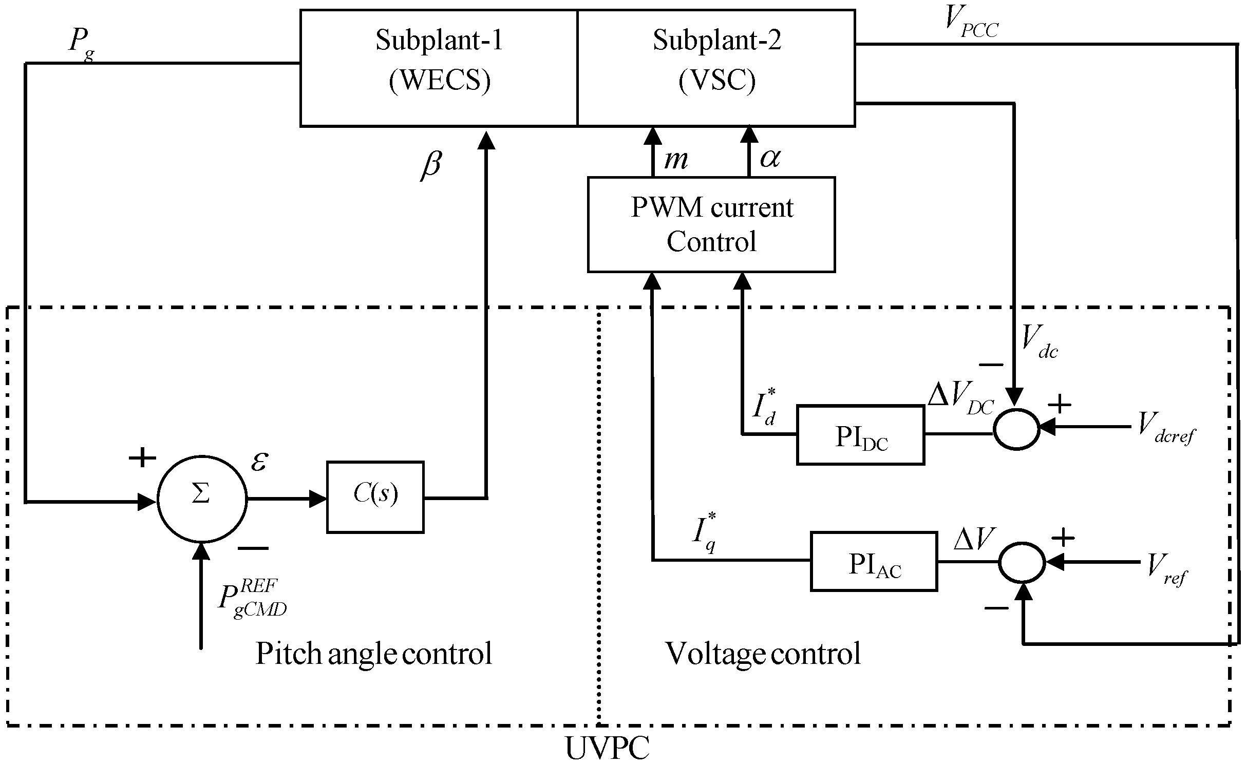
In this study, therefore, simultaneous control of STATCOM and pitch angle controller are employed to smooth the voltage and output power fluctuations of the wind generator subjected to below-rated wind speed disturbances. Figure 8 shows a proposed UVPC control scheme (dotted box) comprising pitch angle and voltage control loops. During the wind speed disturbances, the UVPC voltage control loops especially AC voltage controller generate a proper quadratic current command () which decide the amount of reactive power to be compensated by STATCOM. Besides, the pitch angle control loop of UVPC can smooth the active power of generator by controlling the mechanical torque through suitable pitch angle generation.
In order to achieve the successful reduction in power fluctuations and voltage regulation, the pitch angle and voltage controllers of UVPC need to be designed with an effective control technique. However, while the STATCOM voltage control loops designed by using conventional PI controller offered satisfactory performance, but in pitch angle control loop the PI controller design is not a good choice since the controller is required to work under below-rated wind speed variations [25]. In this trend, an advanced type-2 fuzzy logic controller is the best choice than a traditional fuzzy logic counterpart, since it can handle higher uncertainty levels to produce better performance than the traditional fuzzy logic controller (type-1 FLC) [32]. The primary membership grade of a type-2 FLC is a normal fuzzy set in [0, 1] and the secondary membership is a crisp number in [0, 1] [33]. The range of uncertainty and secondary membership function are decided by the third dimension of type-2 fuzzy sets and footprint-of-uncertainty (FOU), respectively. Thus, in the design of type-2 FLC, these features can offer additional degree-of-freedom to handle various uncertainties. The following subsections discuss the designing part of the interval type-2 FLC for the pitch angle controller.
5.1. A type-2 FLC Design Algorithm for Pitch Angle Controller
Figure 9 shows the steps involved in the type-2 FLC design algorithm.
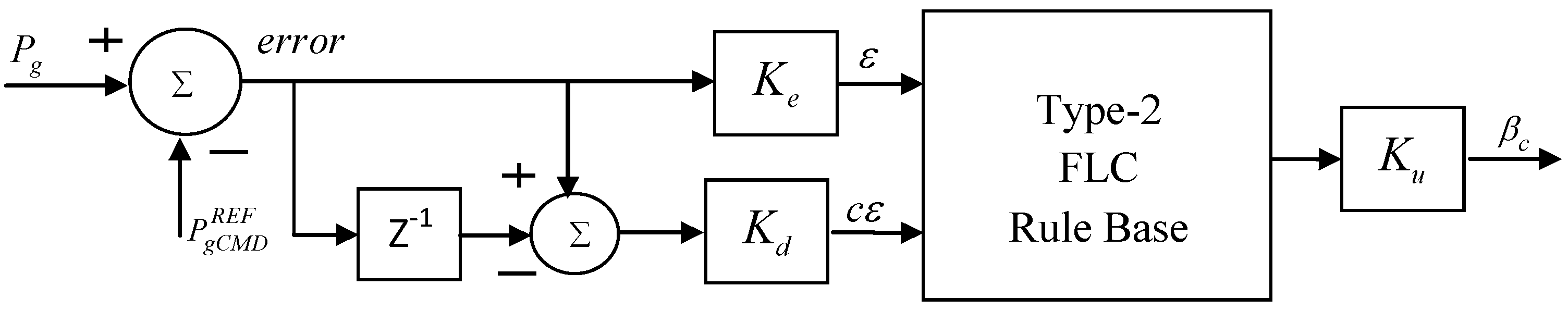
At first, with help of various membership functions the crisp input is converted to fuzzy inputs using the type-2 membership functions of various system parameters so as to account for the uncertainty involved in the expert knowledge. Then using logical operators, a set of fuzzy rules have been framed to combine the fuzzy output sets into a single set under the inference mechanism. Using type reduction operation the output of inference engine is converted to type-1 fuzzy set then the crisp output is obtained from type reduced sets using various defuzzification methods as done in the traditional fuzzy logic (type-1 FLC). To achieve the better smoothing in generator output power during the below-rated wind speed disturbances, the pitch angle controller C(s) of the UVPC (see Figure 8) is replaced with an interval type-2 fuzzy logic controller and the proposed structure is as shown in Figure 10.
The controller gains Ke and Kd are used as a scaling gains for input and Ku for the output signals. These scaling gains can be variables or constants, and during the FLC design these can play an important role to achieve suitable steady-state and transient-state responses. In this work these gains considered to be constant and chosen by a trial and error method as Ke =1, Kd = 100 and Ku =10.
5.1.1. Fuzzificztion
The difference between Pg and goes through the Type-2 FLC as an error (ε) and change in error (cε) signals which are fuzzified by employing seven triangular linguistic variables MFs. The notation for the fuzzy sets is: Negative Large (NL), Negative Medium (NM), Negative Small (NS), Zero (ZR), Positive Small (PS), Positive Medium (PM), and Positive Large (PL). The designed MFs of type-2 FLCs are shown in Figure 11. The MFs are selected based on prior knowledge and observations from the various simulation results. For all the inputs and outputs the universe of discourse is chosen as [−1, +1].
5.1.2. Fuzzy logic rules/Inference Engine
The major function in the inference engine is the rules’ implementation, aggregation and type reduction. With help of the experts’ knowledge on the controllers, a control strategy framed as a set of IF-THEN rules and is as:
If (ε is x1) and (cε is y1) then (βC is w1)
Similarly, 49 rules have been defined for all input-output MFs as shown in Table 1. In the type-2 FLCs, the union and intersection functions are defined by join and meet operations to map the input and output sets with fired rules. A detailed mathematical relation between the meet and join operations is presented in [33]. During the aggregation operation, all the fired rules are converted to become a single output fuzzy set. However, due to computational limitations the output of inference engine cannot be converted directly to crisp value. Thus, type reduction (TR) method has been suggested in the type-2 FLC system to obtain type-1 fuzzy sets from type-2 output fuzzy sets, and later the normal defuzzification techniques can be applied. Height, center-of-sets, center-of-sums and modified-height are the most accepted TR methods [34], in which centroids of the embedded type-2 sets are calculated. In the present work ‘height’ TR method has been used for the calculation of the centroid of type-2 FLCs as it involves much lesser computations as compared to other methods [34].
5.1.3. Defuzzification
The common defuzzification methods used for the type-2 FLC are the first (or last) of maxima, centroid-of-area and mean-of-max methods. In this study, centroid-of-area method has been utilized which is the most reasonable and popular method among the others. The centroid of the type-2 fuzzy set is the collection of centroids of all of its embedded sets. The defuzzification method converts the output fuzzy to crisp value.
6. Results and Discussion
In order to observe the power smoothing and voltage regulation capability contributed by the proposed UVPC, the test system employed is as shown in Figure 1. Figure 12 shows the employed below-rated wind speed data for the simulation study. To evaluate the effectiveness of UVPC strategy three cases have been considered as case 1: System without compensation (i.e., without STATCOM and pitch angle controller), case 2: System with STATCOM, and case 3: System with STATCOM and pitch angle control i.e., UVPC.
6.1. Case 1: System without Compensation
In this case, the wind power system without compensation (i.e., without STATCOM and pitch angle control) has been considered and subjected to below-rated wind speed variations as shown in Figure 12. The responses of the generator voltage, active power, and rotor speed are as shown in Figure 13a–c.
Figure 13a represents the magnitude of the generator terminal voltage obtained without STATCOM. It is clear that the generator voltage fluctuates significantly as there is no dynamic reactive power compensation. This leads to voltage fluctuations at the PCC in a reasonable range resulting in flicker problems. Therefore, it (voltage flicker) is a major limiting factor with the connection of the wind turbines into weak grids, where the wind penetration level is very high.
Since there is no pitch angle generation without pitch angle controller which ensures no point of limiting the rotor speed as shown in Figure 13c and the wind turbine operates with its maximum possible efficiency. As a result, the generator active power followed the wind speed disturbances and exhibits huge fluctuations as shown Figure 13b. If a large number of wind farms were realized and connected to power system networks leads to grid frequency problems.
6.2. Case 2: System with STATCOM
In this case, the STATCOM is employed and connected to the PCC point where the studied wind power system is integrated (see Figure 1). The dynamic responses of the system, subjected to below-rated wind speed variations are as shown in Figure 14a–c. Since the STATCOM provides dynamic reactive power compensation, the voltage fluctuations caused by the wind speed variations were regulated as shown in Figure 14a. Thus, it mitigates the voltage flicker occurring in the wind farm for a smooth grid interaction.
Although, the STATCOM improves the voltage fluctuations due to wind speed variations by controlling the reactive power, it does not have any capability to control the active power. As a result, the generator output power follows the wind speed variations since no pitch angle controller was employed and exhibits fluctuations as shown in Figure 14b. Thus, the consequence of power fluctuations leads to network frequency stability problems. Figure 14c shows the amount of reactive power compensation provided by the STATCOM to regulate the generator voltage terminal.
6.3. Case 3: System with STATCOM and Pitch Angle Control (i.e., with UVPC)
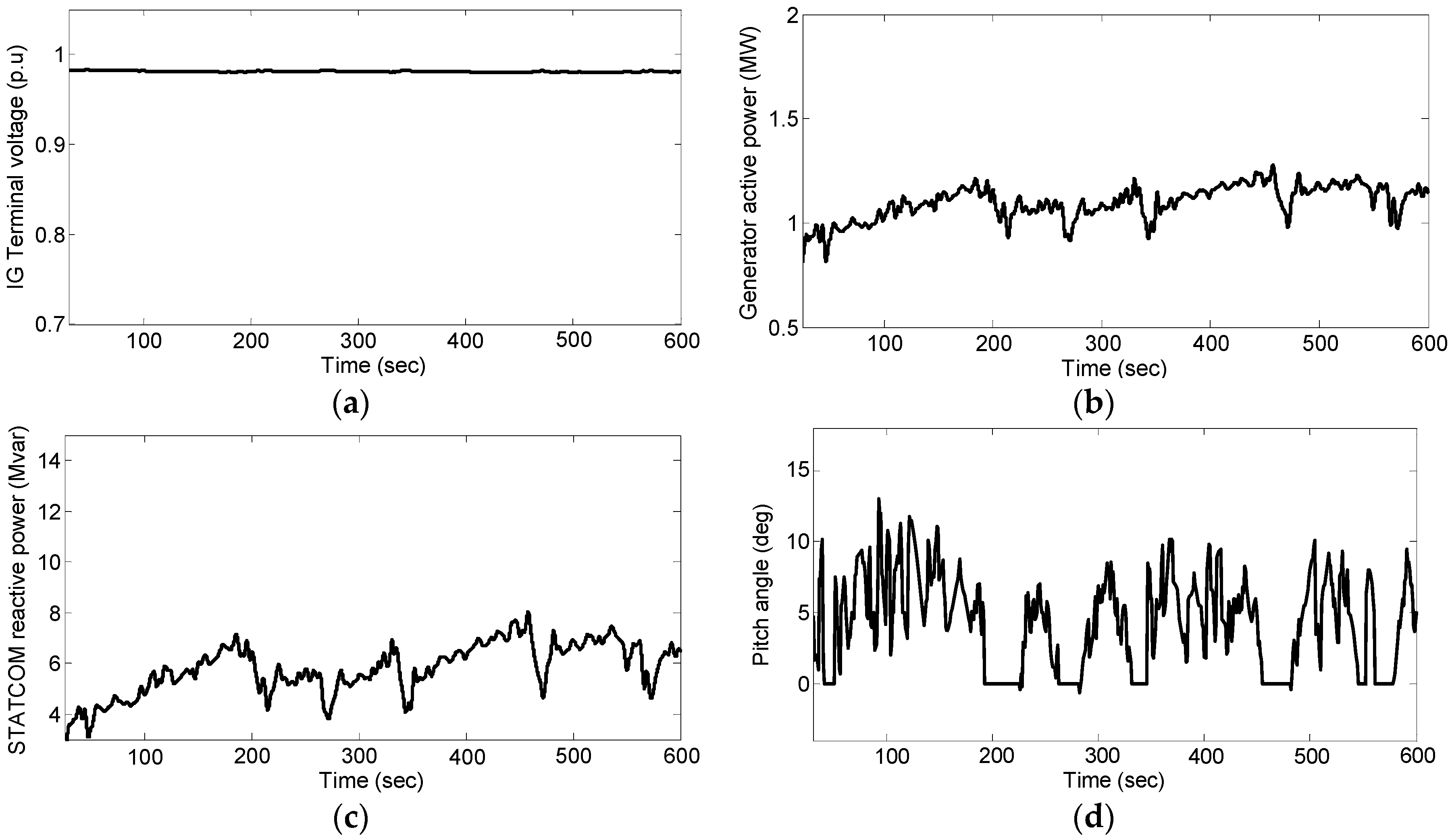
In this case, a control strategy (UVPC) has been employed through which a simultaneous control of STATCOM reactive current and pitch angle were achieved. In addition, to compensate the reactive power required during wind speed disturbances, the proposed strategy can control the mechanical torque by changing the rotor blade angle of the wind turbine leads to active power control. The simulation results obtained with proposed UVPC are as shown in Figure 15a–d.
As discussed earlier, to smoothen the output power fluctuations under below-rated wind speed conditions, first it is required to determine the output command power () and thereafter, fuzzy logic approach (type-2 FLC) has implemented. From Figure 15b, it is observed that the active power output of the wind energy system follows the reference command power and real power fluctuations are being smoothened out more effectively compared to the previous case (see Figure 14b). The pitch angle profile generated by the pitch angle controller for output power smoothing is as shown in Figure 15d. Figure 15a shows the generator voltage regulation achieved with STATCOM reactive power control. The reactive power compensation provided by the STACOM is shown in Figure 15c. By observing the results, it is clear that by employing UVPC strategy simultaneous control of STATCOM and pitch angle control has been achieved which leads to reduction of the generator voltage and active power fluctuations. Moreover, by employing this control strategy the maximum amount of reactive power required for compensation using STATCOM is around 7.5 Mvar where as only with STATCOM (case 2) the amount of reactive power required is around 10 Mvar (see Figure 14c). Thus, for a given operating condition the proposed strategy can reduce the capacity of STATCOM. This is an economical benefit.
6.4. Performance Indices
To estimate the performance of the proposed UVPC, the output power smoothing (Psmooth) and maximum energy (Wmax) functions are calculated as [23]:
where, Pg is the generated output power and T is the total simulation time. In (16), Psmooth is the generated output power (Pg) integration of absolute value for the differentiation. Thus, if Psmooth is small in magnitude, it indicates that the generated output power fluctuations are smoothened-out more.
Figure 16a shows the output power comparison without UVPC i.e., without compensation (case 1) and with UVPC (case 3). It is clearly noticeable from Figure 16a that real output power smoothing has been achieved with the proposed UVPC strategy. Figure 16b shows that the power smoothing function (performance index) obtained with and without UVPC. The proposed method has smaller magnitude as compared to without UVPC throughout the wind speed pattern considered.
Using Equation (17), the maximum energy output of WES obtained over the wind speed disturbance was also determined considering case 1 (without UVPC) and case 3(with UVPC) but one at a time. The plot is as shown in Figure 16c. The maximum energy has been obtained without UVPC as there is no pitch angle generation it remains fixed at zero degrees, but with UVPC there is a drop in the output power due to pitch angle generation. However, the purpose of this work is to smooth the output power and thus drop cannot be avoided.
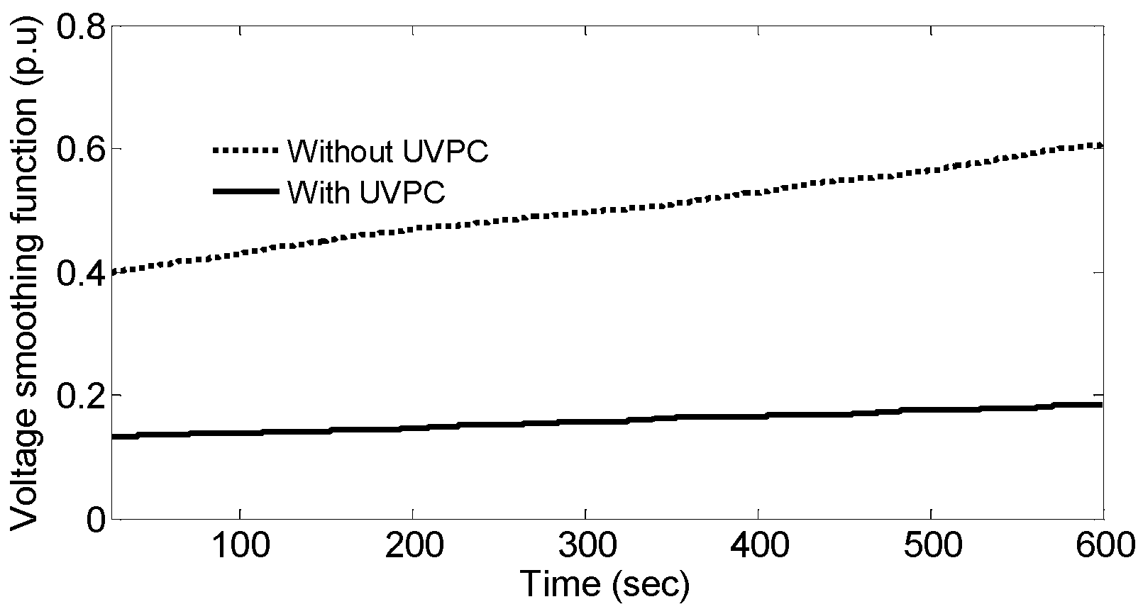
Similarly, the voltage regulation function (performance index) for the wind generator can also be expressed by Equation (18). The corresponding regulation function outcome, with and without UVPC is as shown in Figure 17. It indicates that the voltage regulation function with UVPC possesses smaller magnitude compared to without UVPC throughout the simulation and hence, provides good constant voltage magnitude:
7. Conclusions
In this paper, a unified voltage and pitch angle control (UVPC) strategy has been implemented for a fixed speed wind farm. A novel pitch angle control approach has been incorporated which works under below-rated wind speed. Moreover, an interval type-2 fuzzy logic technique has been employed to design a pitch angle controller, as it is more suitable than traditional fuzzy logic counterparts. Therefore, a new type of pitch angle controller and STATCOM termed as UVPC can smooth the generator active power and regulate the voltage to a constant magnitude subject to below-rated wind speed variations. The simulation results show the suitability of the proposed UVPC control scheme in wind power system applications.
Like the effective output power smoothing achieved with the proposed UVPC scheme, if the system frequency is affected by power fluctuations it can also controlled within an acceptable limit. It is also noticed from the simulation results that by employing the pitch angle controller and STATCOM (case 3), the maximum amount of reactive power required to regulate the generator voltage is around 7.5 Mvar, whereas only with STATCOM (case 2) the amount of reactive power required is around 10 Mvar. This reveals that with the pitch angle controller the capacity of the STATCOM can be minimized. Moreover, if a power storage system is employed to minimize the power fluctuations by including this type of pitch angle controller, then the size of the power storage capacity can be minimized. Although, the drops in the output power due to this type of pitch angle controller cannot be avoided, but if employed along with STATCOM, BESS, SMES and STATCOM with BESS/SMES it can reduce the capacity of the these devices as an economical benefit.
Author Contributions
In this research contribution, Kanasottu Anil Naik is involved in processing phase, data collection, system modelling, simulation and results analysis. Chandra Prakash Gupta supervised the progress of research. Both authors have concluded the scientific findings and prepared the manuscript.
Conflicts of Interest
The authors declare no conflict of interest.
Appendix A
System Parameters
In this appendix, Table A1 provides the simulation parameters of the NM64c/1500 type wind turbine manufactured by Neg Micon (Mecklenburg-Vorpommern, Germany) and the generator parameters in Table A2.

Table A1.
Commercial fixed speed wind turbine parameters [5].
Table A1.
Commercial fixed speed wind turbine parameters [5].
| Parameters | Values |
|---|---|
| Rated power | 1.5 MW |
| Rotor diameter | 64 m |
| Number of blades | 3 |
| Cut-in wind speed () | 4 m/s |
| Cut-out wind speed () | 25 m/s |
| Rated wind speed () | 14 m/s |
| Generator | SCIG |
Table A2.
SCIG generator parameters [35].
Table A2.
SCIG generator parameters [35].
| Parameters | Values |
|---|---|
| Prated, Vrated | 1.5 MW, 0.69 kV |
| Rs, Rr | 0.004843 p.u., 0.004377 p.u. |
| Ls, Lr | 0.1248 p.u., 0.1791p.u. |
| Lm, H | 6.77 p.u., 5.04 (s) |
| C | 200 kVAR |
References
- The Global Wind Energy Council Belgium. Available online: http://www.gwec.net/global-Figures/wind-in-numbers/ (accessed on 5 August 2017).
- De Mello, F.P.; Feltes, J.W.; Hannett, L.N.; White, J.C. Application of induction generators in power system. IEEE Trans. Power Appar. Syst. 1982, 101, 3385–3393. [Google Scholar] [CrossRef]
- Rekioua, D. Wind Power Electrical Systems, Modeling, Simulation and Control 2014 Series: Green Energy and Technology; Springer: London, UK, 2014. [Google Scholar]
- Taraft, S.; Rekioua, D.; Aouzellag, D.; Bacha, S. A proposed strategy for power optimization of a wind energy conversion system connected to the grid. Energy Convers. Manag. 2015, 101, 489–502. [Google Scholar] [CrossRef]
- The Wind Power. Available online: http://www.thewindpower.net/windfarm_en_86_challicum-hills.php (accessed on 5 May 2017).
- Kim, Y.; Kang, M.; Muljadi, E.; Park, J.W.; Kang, Y.C. Power Smoothing of a Variable-Speed Wind Turbine Generator in Association with the Rotor-Speed-Dependent Gain. IEEE Trans. Sustain. Energy 2017, 8, 990–999. [Google Scholar] [CrossRef]
- Vanitha, V.; Shreyas, S.; Vasanth, V. Fuzzy Based Grid Voltage Stabilization in a Wind Farm Using Static VAR Compensator. In Proceedings of the International Conference on Advances in Recent Technologies in Communication and Computing, Kottayam, Kerala, 27–28 October 2009; pp. 14–18. [Google Scholar]
- Molinas, M.; Suul, J.A.; Undeland, T. Low Voltage Ride Through of Wind Farms with Cage Generators: STATCOM versus SVC. IEEE Trans. Power Electron. 2008, 23, 1104–1117. [Google Scholar] [CrossRef]
- Qiao, W.; Harley, R.G. Power Quality and Dynamic Performance Improvement of Wind Farms Using a STATCOM. In Proceedings of the IEEE Power Electronics Specialists Conference, Orlando, FL, USA, 17–21 June 2007; pp. 1832–1838. [Google Scholar]
- Fadaeinedjad, R.; Moschopoulos, G.; Moallem, M. Using STATCOM to mitigate voltage fluctuations due to aerodynamic aspects of wind turbines. In Proceedings of the IEEE Power Electronics Specialists Conference, Rhodes, Greece, 15–19 June 2008; pp. 3648–3654. [Google Scholar]
- Xu, Z. Improvement of power quality and dynamic voltage of wind farms using an inductive filtering method. In Proceedings of the IEEE International Conference on Environment and Electrical Engineering (EEEIC), Rome, Italy, 10–13 June 2015; pp. 1611–1615. [Google Scholar]
- Mondol, N.; Sheikh, M.R.I.; Hasan, M.R. Stabilization of wind firm integrated Hybrid Power System by using STATCOM. In Proceedings of the International Conference on Electrical & Electronic Engineering (ICEEE), Rajshahi, Bangladesh, 4–6 November 2015; pp. 105–108. [Google Scholar]
- Muyeen, S.M.; Ali, M.H.; Takahashi, R.; Murata, T.; Tamura, J. Stabilization of Wind Farms Connected with Multi Machine Power System by Using STATCOM. In Proceedings of the IEEE Lausanne Power Tech, Lausanne, Switzerland, 1–5 July 2007; pp. 299–304. [Google Scholar]
- Tian, G.; Wang, S.; Liu, G. Power quality and transient stability improvement of wind farm with fixed-speed induction generators using a STATCOM. In Proceedings of the International Conference on Power System Technology, Hangzhou, China, 24–28 October 2010; pp. 1–6. [Google Scholar]
- Wang, L.; Hsiung, C.T. Dynamic Stability Improvement of an Integrated Grid-Connected Offshore Wind Farm and Marine-Current Farm Using a STATCOM. IEEE Trans. Power Syst. 2011, 26, 690–698. [Google Scholar] [CrossRef]
- Zhang, L.; Shen, C.; Crow, M.L.; Dong, L.; Pekarek, S.; Atcitty, S. Performance Indices for the Dynamic Performance of FACTS and FACTS with Energy Storage. Electr. Power Compon. Syst. 2005, 33, 299–314. [Google Scholar] [CrossRef]
- Arulampalam, A.; Barnes, M.; Jenkins, N.; Ekanayake, J.B. Power quality and stability improvement of a wind farm using STATCOM supported with hybrid battery energy storage. IEE Proc. Gener. Transm. Distrib. 2006, 153, 701–710. [Google Scholar] [CrossRef]
- Muyeen, S.M.; Ali, M.H.; Takahashi, R.; Murata, T.; Tamura, J. Wind Generator Output Power Smoothing and Terminal Voltage Regulation by Using STATCOM/ESS. In Proceedings of the IEEE Lausanne Power Tech, Lausanne, Switzerland, 1–5 July 2007; pp. 1232–1237. [Google Scholar]
- Sheikh, M.R.I.; Eva, F.; Motin, M.A.; Hossain, M.A. Wind generator output power smoothing and terminal voltage regulation by using STATCOM/SMES. In Proceedings of the International Conference on the Developments in Renewable Energy Technology (ICDRET 2012), Dhaka, Bangladesh, 5–7 January 2012; pp. 1–5. [Google Scholar]
- Ning-Ning, L.; Yi-Qi, L.; Yan-Chao, J.; Jian-Ze, W.; Ke, S. Power fluctuation alleviation using cascade STATCOMs with energy storages for wind farm applications. In Proceedings of the International Conference on Electrical Machines and Systems (ICEMS), Hangzhou, China, 22–25 October 2014; pp. 1334–1339. [Google Scholar]
- Hossain, M.J.; Pota, H.R.; Ugrinovskii, V.A.; Ramos, R.A. Simultaneous STATCOM and Pitch Angle Control for Improved LVRT Capability of Fixed-Speed Wind Turbines. IEEE Trans. Sustain. Energy 2010, 1, 142–151. [Google Scholar] [CrossRef]
- Doostabad, H.H.; Khalghani, M.R.; Khooban, M.H. A novel control system design to improve LVRT capability of fixed speed wind turbines using STATCOM in presence of voltage fault. Int. J. Electr. Power Energy Syst. 2016, 77, 280–286. [Google Scholar] [CrossRef]
- Senjyu, T.; Sakamoto, R.; Urasaki, N.; Funabashi, T.; Fujita, H.; Sekine, H. Output power leveling of wind turbine Generator for all operating regions by pitch angle control. IEEE Trans. Energy Convers. 2006, 21, 467–475. [Google Scholar] [CrossRef]
- Senjyu, T.; Sakamoto, R.; Kaneko, T.; Yona, A.; Funabashi, T. Output power leveling of wind farm using pitch angle controller with fuzzy neural networks. Electr. Power Compon. Syst. 2008, 36, 1048–1066. [Google Scholar] [CrossRef]
- Duong, M.Q.; Grimaccia, F.; Leva, S.; Mussetta, M.; Ogliari, E. Pitch angle control using hybrid controller for all operating regions of SCIG wind turbine system. Renew. Energy 2014, 70, 197–203. [Google Scholar] [CrossRef]
- Hagras, H.; Wagner, C. Towards the wide spread use of type-2 fuzzy logic systems in real world applications. IEEE Comput. Intell. Mag. 2012, 7, 14–24. [Google Scholar] [CrossRef]
- Mendel, J.M.; John, R.I.; Liu, F. Interval type-2 fuzzy logic systems made simple. IEEE Trans. Fuzzy Syst. 2006, 14, 808–821. [Google Scholar] [CrossRef]
- Qilian, L.; Mendel, J.M. Interval type-2 fuzzy logic systems: Theory design. IEEE Trans. Fuzzy Syst. 2000, 8, 535–550. [Google Scholar] [CrossRef]
- Ackerman, T. Wind Power in Power System; John Wiley & Sons Ltd.: Chichester, UK, 2005. [Google Scholar]
- Singh, B.; Murthy, S.S.; Gupta, S. STATCOM-Based Voltage Regulator for Self-Excited Induction Generator Feeding Nonlinear Loads. IEEE Trans. Ind. Electron. 2006, 53, 1437–1452. [Google Scholar] [CrossRef]
- INVESTOPEDIA. Available online: http://www.investopedia.com/articles/trading/10/simple-exponential-moving-averages-compare.asp (accessed on 15 June 2017).
- Mendel, J.M. Computing with words when words can mean different things to different people. In Proceedings of the International ICSC Congress on Computational Intelligence: Methods and Applications, 3rd Annual Symposium on Fuzzy Logic and Applications, Rochester, NY, USA, 22–25 June 1999; pp. 1–7. [Google Scholar]
- Mizumoto, M.; Tanaka, K. Some properties of fuzzy sets of type 2. Inf. Control 1976, 31, 312–340. [Google Scholar] [CrossRef]
- Karnik, N.N.; Mendel, J.M. Type-2 fuzzy logic systems. IEEE Trans. Fuzzy 1999, 7, 643–658. [Google Scholar] [CrossRef]
- Haque, M.H. Evaluation of power flow solutions with fixed speed wind turbine generating systems. Energy Convers. Manag. 2014, 79, 511–518. [Google Scholar] [CrossRef]
Figure 1.
Single line diagram of the studied system.
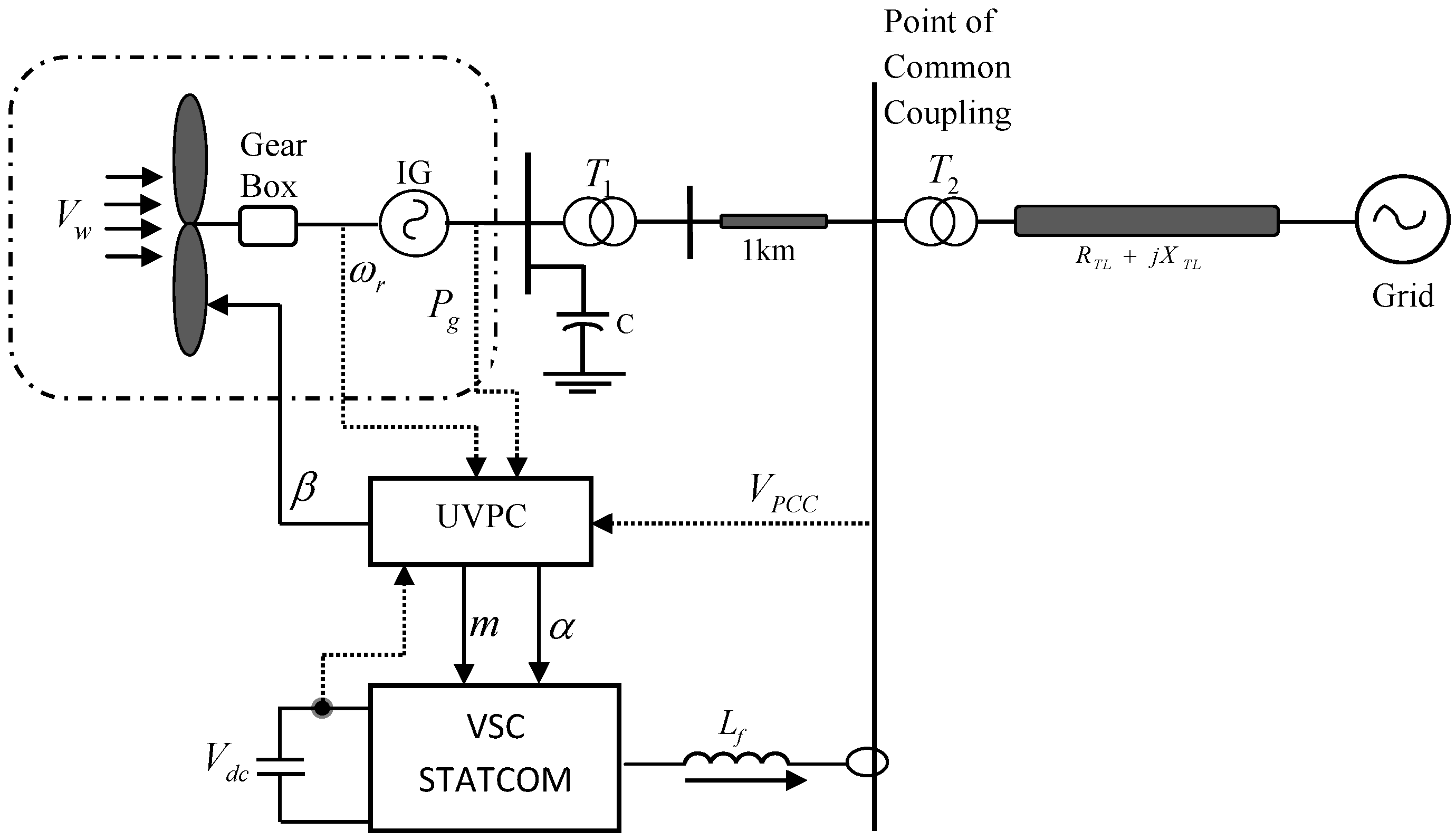
Figure 2.
Performance coefficient Cp (λ, β) curve.

Figure 3.
d-q reference frame of the induction generator: (a) d-axis; (b) q-axis.

Figure 4.
Block diagram of the control scheme of STATCOM.
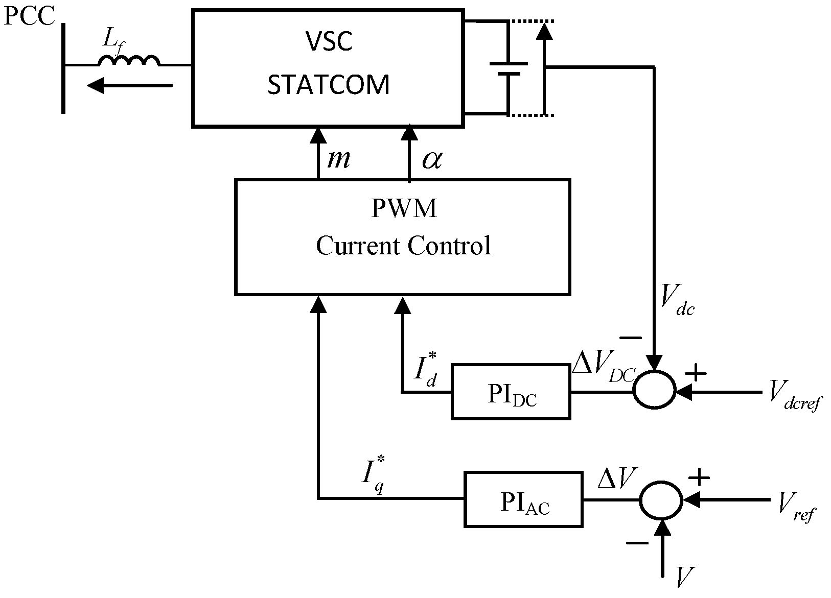
Figure 5.
Proposed pitch angle controller.

Figure 6.
Comparison of wind speed and EMA.

Figure 7.
Computation of controller input power command.
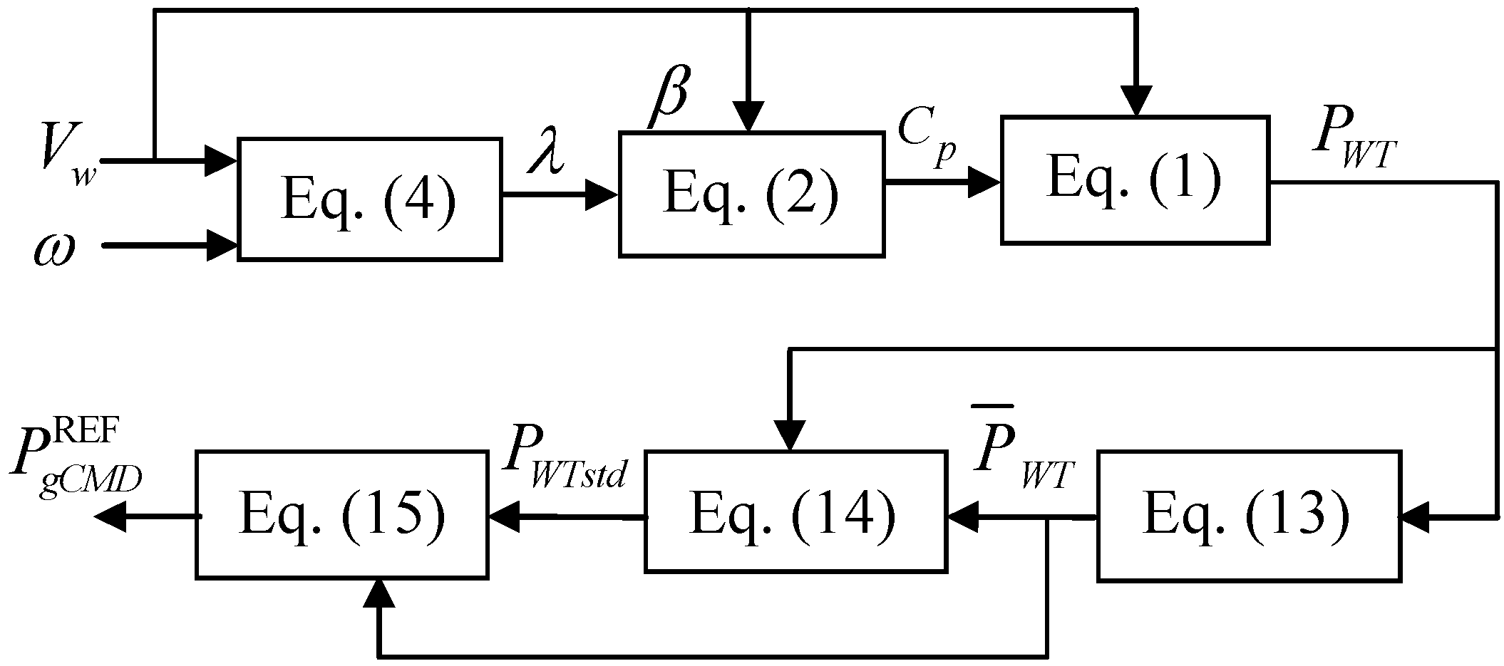
Figure 8.
Block diagram of the proposed UVPC.

Figure 9.
Schematic diagram of type-2 FLC.
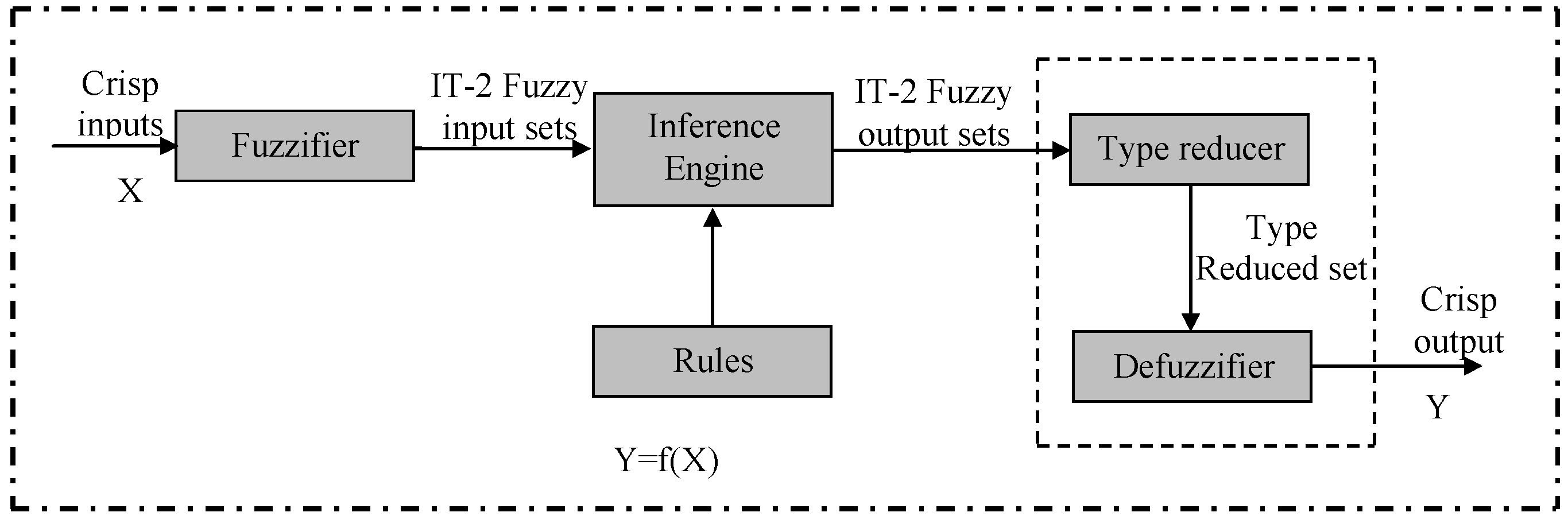
Figure 10.
Proposed structure of type-2 FLC based pitch angle controller.

Figure 11.
Type-2 FLC designed membership function.

Figure 12.
Wind speed profile.
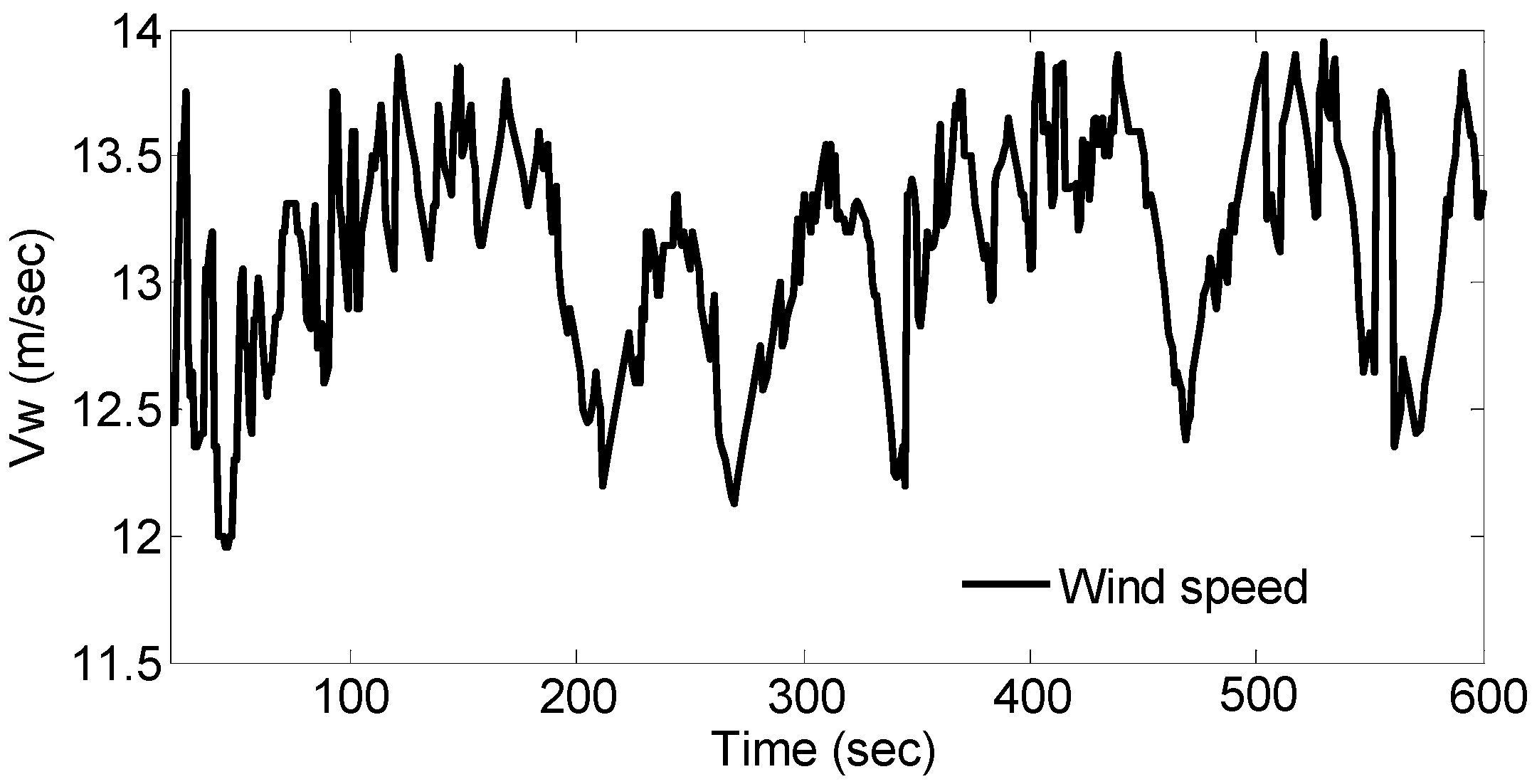
Figure 13.
Dynamic response of the system without compensation subjected to below-rated wind speed: (a) Generator terminal voltage; (b) Generator output power; (c) Generator rotor speed.
Figure 13.
Dynamic response of the system without compensation subjected to below-rated wind speed: (a) Generator terminal voltage; (b) Generator output power; (c) Generator rotor speed.
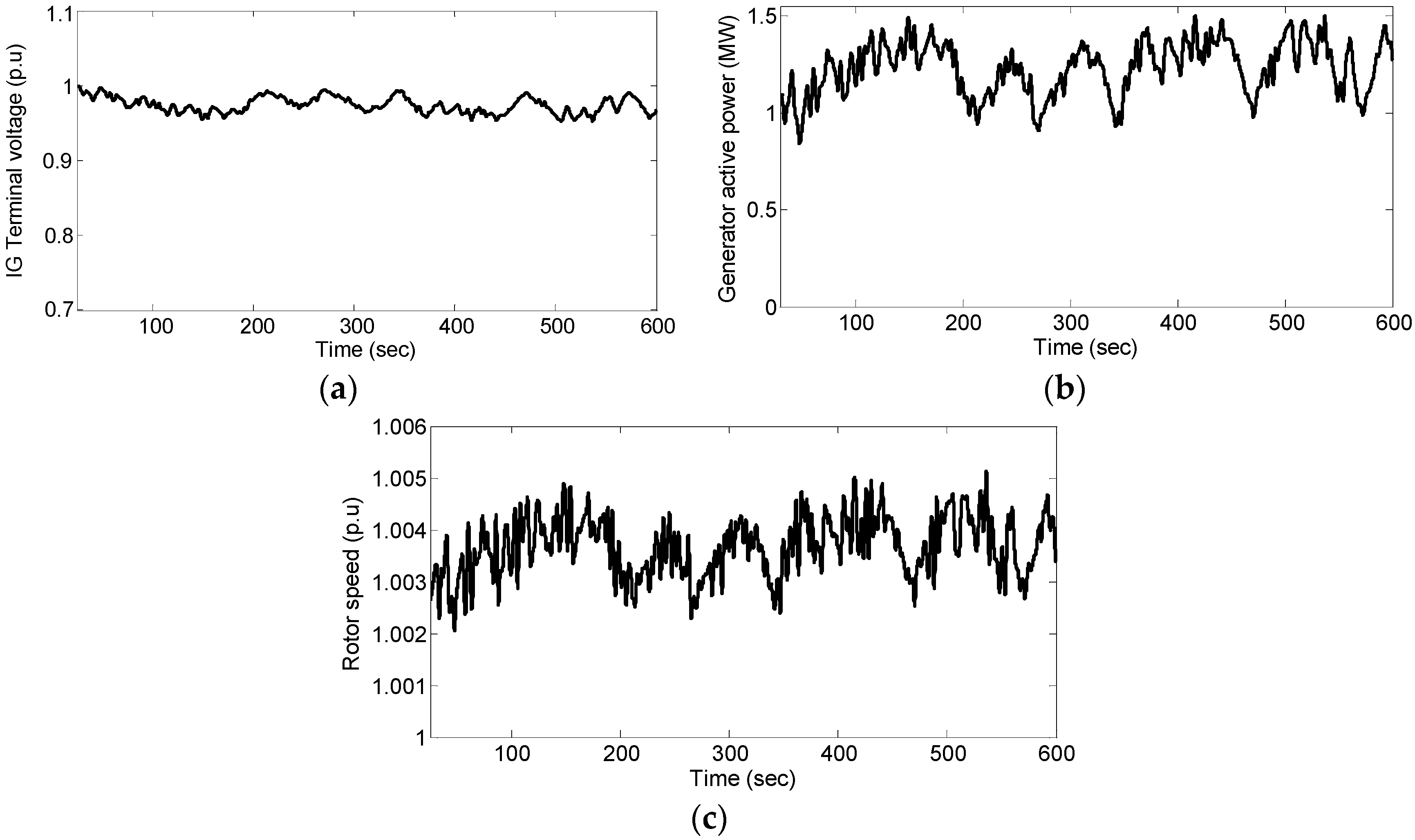
Figure 14.
Dynamic response of the system with STATCOM subjected to below-rated wind speed: (a) Generator terminal voltage; (b) Generator output power; (c) STATCOM reactive power compensation.
Figure 14.
Dynamic response of the system with STATCOM subjected to below-rated wind speed: (a) Generator terminal voltage; (b) Generator output power; (c) STATCOM reactive power compensation.
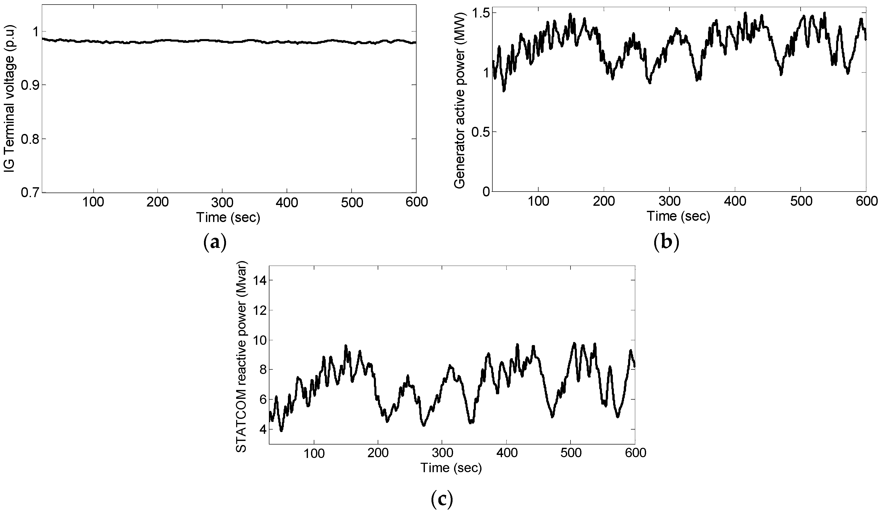
Figure 15.
Dynamic response of the system with STATCOM and pitch angle control i.e., UVPC subjected to below-rated wind speed: (a) Generator terminal voltage; (b) Generator output power; (c) STATCOM reactive power compensation; (d) Pitch angle.
Figure 15.
Dynamic response of the system with STATCOM and pitch angle control i.e., UVPC subjected to below-rated wind speed: (a) Generator terminal voltage; (b) Generator output power; (c) STATCOM reactive power compensation; (d) Pitch angle.

Figure 16.
Performance comparison of system without UVPC and with UVPC: (a) Generator active power; (b) Generator output power smoothing function; (c) Maximum energy function.
Figure 16.
Performance comparison of system without UVPC and with UVPC: (a) Generator active power; (b) Generator output power smoothing function; (c) Maximum energy function.
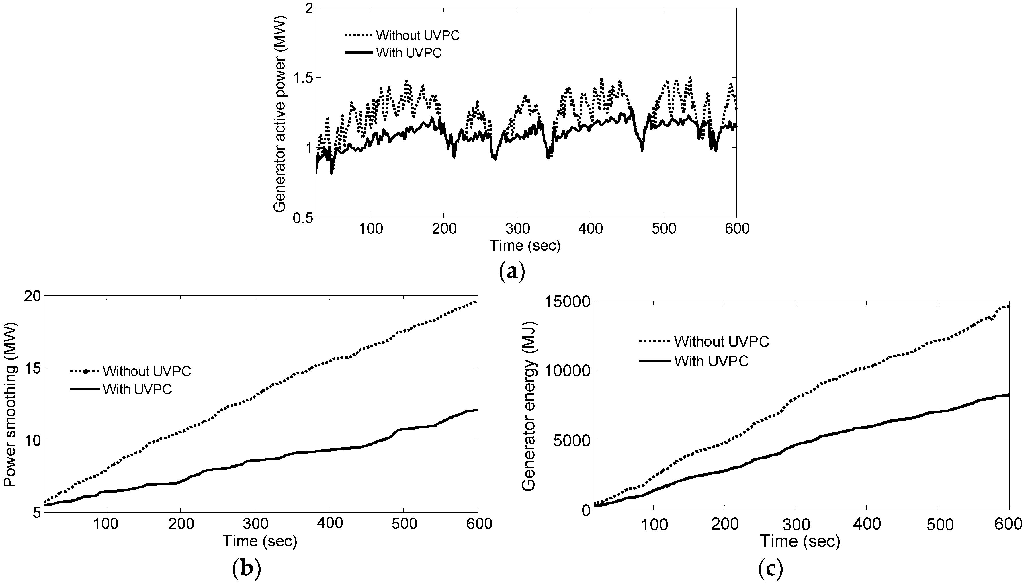
Figure 17.
Generator terminal voltage regulation function.

Table 1.
Controller rules.
| Change in Error () | Error () | ||||||
|---|---|---|---|---|---|---|---|
| NL | NM | NS | ZR | PS | PM | PL | |
| NL | NL | NL | NL | NL | NM | NS | ZR |
| NM | NL | NL | NL | NL | NS | ZR | PS |
| NS | NL | NL | NM | NM | ZR | PS | PM |
| ZR | NL | NM | NS | ZR | PS | PM | PL |
| PS | NM | NS | ZR | PM | PM | PL | PL |
| PM | NS | ZR | PS | PM | PL | PL | PL |
| PL | ZR | PS | PM | PL | PL | PL | PL |
© 2017 by the authors. Licensee MDPI, Basel, Switzerland. This article is an open access article distributed under the terms and conditions of the Creative Commons Attribution (CC BY) license (http://creativecommons.org/licenses/by/4.0/).
Share and Cite
MDPI and ACS Style
Naik, K.A.; Gupta, C.P. Output Power Smoothing and Voltage Regulation of a Fixed Speed Wind Generator in the Partial Load Region Using STATCOM and a Pitch Angle Controller. Energies 2018, 11, 58. https://doi.org/10.3390/en11010058
AMA Style
Naik KA, Gupta CP. Output Power Smoothing and Voltage Regulation of a Fixed Speed Wind Generator in the Partial Load Region Using STATCOM and a Pitch Angle Controller. Energies. 2018; 11(1):58. https://doi.org/10.3390/en11010058
Chicago/Turabian StyleNaik, Kanasottu Anil, and Chandra Prakash Gupta. 2018. "Output Power Smoothing and Voltage Regulation of a Fixed Speed Wind Generator in the Partial Load Region Using STATCOM and a Pitch Angle Controller" Energies 11, no. 1: 58. https://doi.org/10.3390/en11010058
Note that from the first issue of 2016, this journal uses article numbers instead of page numbers. See further details here.