Article

Analysis on the Amplitude and Frequency Characteristics of the Rotor Unbalanced Magnetic Pull of a Multi-Pole Synchronous Generator with Inter-Turn Short Circuit of Field Windings

School of Electrical Engineering, Beijing Jiaotong University, Beijing 100044, China
*
Author to whom correspondence should be addressed.
Energies 2018, 11(1), 60; https://doi.org/10.3390/en11010060
Submission received: 3 December 2017 / Revised: 19 December 2017 / Accepted: 25 December 2017 / Published: 1 January 2018
(This article belongs to the Section I: Energy Fundamentals and Conversion)

Abstract

:
Inter-turn short circuit of field windings (ISCFW) is a common generator fault which can result in serious safety accidents for power systems, if the fault is not eliminated in time. Taking advantage of the electrical and mechanical characteristics of the generator after a fault as a fault criterion is a new idea for fault monitoring, so finding out the frequency and amplitude frequency characteristics of rotor unbalanced magnetic pull (UMP)—the vibration excitation source of the fault—is the basis and key of the research. Taking a six-pole generator as an example, the effects of harmonic magnetic motive force (MMF) interaction on rotor UMP, as well as the frequency characteristics of rotor UMP after generator faults in different stator windings, are obtained based on the analysis of the air-gap MMF of the generator after a fault, and the results of theoretical analysis are verified by simulation. Based on the above results, the simulation calculation on rotor UMP of generators with three stator winding forms under different operating conditions has been achieved, to get the relation between rotor UMP amplitude and active power and field current, and to find out the mechanism of rotor UMP amplitude change along with operating conditions and effect of stator winding forms on UMP amplitude by theoretical analysis. The conclusions are of important significance for studying fault mechanical characteristics of generators and lay a foundation for online monitoring on ISCFW by integrating mechanical and electrical information.

1. Introduction

In recent years, the power industry has been developing rapidly, while building size and installed capacity for all kinds of power stations are increasingly being enhanced, therefore, the safety and reliable running of generators is more and more important. Inter-turn short circuit of generator field windings (ISCFW) incidents easily occur, as a result of coil extrusion and friction against each other during high-speed running or frequent start-ups. The slight short circuit faults won’t apparently affect generator running [1], but if these faults can’t be removed in time, it will cause the field current of the generator to increase, output reactive power to reduce, unit vibration to intensify and shaft neck and bearing bush to be burned, which will seriously threaten the safe and stable running of the generator and power system [2]. For the reason that the ISCFW can result in serious hidden dangers, running failures of generator could be effectively avoided to guarantee safe and stable running of power systems [3], if such faults can be monitored during generator running to find and remove small-turn short circuits in time.
Domestic and overseas scholars have made lots of studies on theories and methods in monitoring ISCFW of generators [4,5,6] and put forward the coil detection method and shock pulse method based on magnetic field detection and electrical quantity monitoring method during operation. However, these existing monitoring methods have corresponding defects and limitations. The coil detection method is an earlier way to detect this fault which is realized by extracting the fault magnetic field features by means of a detection conductor or coil in the air gap. Reference [7] described that the comparative measurement of the magnetic flux density produced by each winding can provide a coil detection method by placing a measuring coil tangentially and near to the rotor; Reference [8] analyzed the magnetic field in detail for several operating conditions under healthy and faulty states which are difficult or even impossible to carry out by available measurement methods in industrial environments and realizes on-line condition monitoring by the permanent installation of a flux probe on the stator to measure the rotor magnetic flux. The disadvantages of this method is that detection coils must be installed on the generator, which is hard to realize for generators that have already been put into operation.
The shock impulse method achieves the fault monitoring by the analysis of the response curve of the pulse signal at both ends of the excitation winding. The technique for the ISCFW detection of generators through the twin-signal sensing method is described in detail in [9]. The reflected signals can produce a signature signal that contains information about the rotor’s state. The development of power electronic circuits for generation of the twin signals and detection of the reflected signals has been described in [10]. The design and fabrication of a lab model to test this technique is summarized along with the results of laboratory experiments. However, this method is generally applicable to off-line monitoring of faults, and it’s not an ideal method for on-line monitoring.
The current main ISCFW detection method is to use the electrical quantities of the generator in operation. Several scholars have proposed that the harmonic characteristic of field currents could be used to detect ISCFW [11,12]. However, the ac components of a field current in fault are usually so small that the monitoring sensitivity is very low. There is another straightforward fault monitoring method which is to use the even order harmonic circular current of two generator stator parallel branches [13,14]. This monitoring method faces problems such as a low monitoring sensitivity, large monitoring blind zone, and current transformers cannot be installed on most turbines as well. Therefore, domestic and overseas scholars have been looking for a new monitoring scheme.
It is a new thought of research to make use of the mechanical vibration characteristics of a generating unit during a fault as an auxiliary criterion for fault monitoring. The greatest advantage of using the integration of mechanical and electrical characteristics after faults as the criteria for fault monitoring is that it can effectively reduce fault monitoring dead zones and make up for individual use defects such as the impossible of installing current transformer for some turbines. After ISCFW occurs, the air-gap field will be distorted, and generator rotor will be affected by unbalanced magnetic pull (UMP), thus the rotor will generate a radial vibration [15]. This provides the possibility to realize ISCFW on-line monitoring by means of collecting the generator rotor vibration signal of rotor and finding out the unique rotor mechanical fault characteristics. Therefore, the analysis on excitation source of vibration—UMP is the basis and key for studying the mechanical characteristics of faults and is of important significance for the realization of fault diagnosis based on the integration of mechanical and electrical information. There are some scholars who have explored and studied the characteristics of rotor UMP and vibration in faults. Reference [16] investigated the radial rotor vibration characteristics under static air-gap eccentricity and stator inter-turn short circuit composite faults. The vibration response characteristics based on the UMP model for the generator rotor are calculated and analyzed in [17]. Reference [18] analysed the rotor UMP of a turbo-generator with an air gap eccentricity fault under multiple loading conditions.
However, there are still many deficiencies in the current UMP studies. First, none of the above studies have considered the effect on vibration of the various space harmonic fields, which are generated by the rotor and stator time harmonic current after the failure. Especially, the prior studies on UMP have failed to probe the impacts of different magnetic field interactions on the UMP variations, which is crucial to reveal the influence of the failure mechanism on vibration. Second, there is a lack of enough explorations on the effect of stator winding form on UMP, which is key to the applications of research results to different types of generators. Third, the existing investigations on the effect of generator operating conditions on rotor UMP are not detailed enough because most of them concentrate on superficial phenomena and lack a strict theoretical analysis.
In order to cover the three shortcomings in existing research and the problems faced, this paper presents a more detailed and in-depth study on the amplitude and frequency characteristics of generator rotor UMP with ISCFW. In the first section, a detailed theoretical analysis on the post-fault harmonic magnetic motive force (MMF) in the air gap of a generator is carried out, to get the effect of interacted space MMF on rotor UMP for the first problem above. In the second section, for solving the second problem, the frequency characteristics of rotor UMP of a generator with different stator winding forms after faults were analyzed in detail, and the analytical results were verified by simulations. In the third section, a comparatively comprehensive analysis on the UMP amplitude variation characteristics with different operating conditions through sufficient theoretical analysis and simulations has been achieved to supplement the third insufficient current research on UMP. The influences of stator winding form on the UMP amplitude variation trends with operating conditions are discussed and the relationships between generator operating conditions and UMP amplitudes are obtained, which are vital to probe the rotor vibration response characteristics of generators with ISCFW. The above three points are the main innovations of this paper compared with previous studies. The conclusions of this research provide a basis for the investigations on rotor vibration features with ISCFW and lay a foundation for on-line monitoring of rotor inter-turn short circuits, based on the integration of mechanical and electrical information.

2. Frequency Characteristics Analysis of Rotor UMP

2.1. MMF Analysis during ISCFW

When the generator rotor of P pairs of poles encounters ISCFW, the symmetry of the field winding is destroyed, so that MMF generated by direct component of field current not only contains the space fundamental wave and odd harmonics of normal running (the alternating component is relatively smaller, so its effect isn’t considered), but also contains spatial even harmonics and fractional harmonics (1-pole generator contains no fractional harmonics) such as 1/P-th and 2/P-th. The rotor MMF is expressed on stator coordinate as follows:
F r ( θ , t ) = λ F r , λ sin [ P λ ( θ ω 0 t P ) ]
where Fr,λ is amplitude of the λ-th harmonic MMF, generated by direct component of field current; ω0 is synchronous angular velocity and θ is mechanical angle of the stator coordinates.
The space harmonic MMF arising from a fault can induce odd harmonics and fractional harmonics in different branches of the same phase of the stator windings. These harmonic current and stator fundamental current will generate space MMF with different rotational speed, rotational direction and pole pairs:
F s ( θ , t ) = μ ν F s , μ , ν sin ( P v θ ± μ ω 0 t + φ s , μ , v )
where Fs,μ,ν and φs,μ,ν, respectively, represents amplitude and phase of ν-th space MMF generated by the μ-th time harmonic current of the stator armature. When space MMF rotates clockwise, ± is +, otherwise, ± is −.

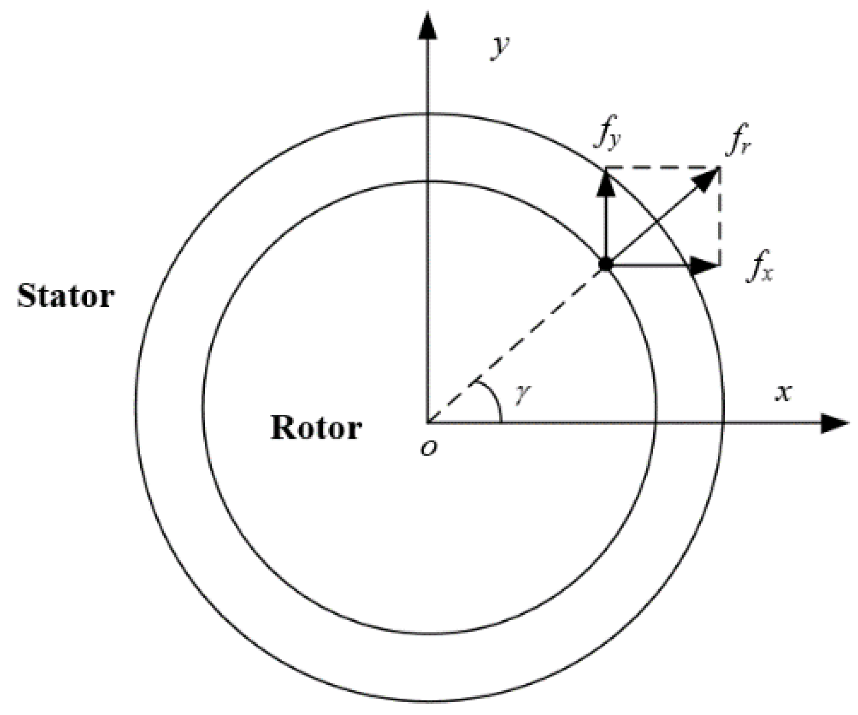
2.2. Calculation of Rotor UMP

Generally, for the non-salient pole generator, the air gap magnetic circuit is uniform and if the position along stator coordinate is the same, its air gap length l will be the same. By the air gap MMF obtained from Section 2.1, the air gap magnetic field density B during a fault can be calculated as follows:
B ( θ , t ) = μ 0 l [ F s ( θ , t ) + F r ( θ , t ) ]
where μ0 is the space permeability. By the Maxwell stress tensor method, the radial electromagnetic density along any point of rotor surface fr can be calculated:
f r = B 2 ( θ , t ) 2 μ 0
The radial electromagnetic density is disintegrated into fx along axis x and fy along axis y, as shown in Figure 1 and Equation (5):
{ f x = f r cos θ f y = f r sin θ
The electromagnetic density is integrated along rotor surface to get axial component Fx of rotor UMP at fault along axis x and axial component Fy along axis y:
{ F x = 1 2 L r D r 0 2 π f x d θ F y = 1 2 L r D r 0 2 π f y d θ
where Lr and Dr respectively represent the axial length and diameter of the generator rotor .

2.3. Analysis on Role of Space MMF on UMP

The component along axis x of rotor UMP and that along axis y can be analyzed in a similar manner, therefore, this paper only analyzes Fx along axis x. To simplify the formula, some parameter settings are necessary as follows: mμ,ν = Pνθ ± μω0t + φs,μ,ν and nr,λ = (θω0t/P), then Fx can be expressed as follows:
F x = μ 0 L r D r 2 l 2 0 2 π [ μ ν F s , μ , ν sin m μ , v + λ F r , λ sin n r , λ ] 2 cos θ d θ

2.3.1. Effect of the Same Harmonic MMF Respectively Generated by Rotor and Stator on UMP

In Equation (7), the common harmonic MMF generated by the stator or rotor can be respectively expressed as follows:
K x , s , v = F s , μ , ν 2 sin 2 m μ , v cos θ = 1 4 F s , μ , ν 2 [ cos ( 2 m μ , v θ ) + 2 cos θ cos ( 2 m μ , v + θ ) ]
K x , r , λ = F r , λ 2 sin 2 n r , λ cos θ = 1 4 F r , λ 2 [ cos ( 2 n r , λ θ ) + 2 cos θ cos ( 2 n r , λ + θ ) ]
When variable θ is integrated within [0, 2π], the integral results of 2 cos θ in Equations (8) and (9) are 0. The harmonic orders of space MMF generated by stator and rotor during inter-turn short circuit of field windings (ISCFW) are respectively v = i / P , i = 1 , 2 , 3 , and λ = j / P , j = 1 , 2 , 3 , , then the coefficient 2 P v ± 1 of θ in cos ( 2 m μ , v ± θ ) and cos ( 2 n r , λ ± θ ) is not 0, thus the integral results will always be 0.
From the above analysis, it is conclusion that the same harmonic MMF generated by stator or rotor won’t affect UMP.

2.3.2. Effect of Two Kinds of Harmonic MMF Generated by Stator or Rotor on UMP

The items with two kinds of harmonic MMF of stator or rotor can be expressed as Equstions (10) and (11):
K x , s , ν 1 , ν 2 = 2 F s , μ 1 , ν 1 F s , μ 2 , ν 2 sin m μ 1 , ν 1 sin m μ 2 , ν 2 cos θ = 1 2 F s , μ 1 , ν 1 F s , μ 2 , ν 2 [ cos ( m μ 1 , ν 1 m μ 2 , ν 2 θ ) cos ( m μ 1 , ν 1 + m μ 2 , ν 2 θ ) + cos ( m μ 1 , ν 1 m μ 2 , ν 2 + θ ) cos ( m μ 1 , ν 1 + m μ 2 , ν 2 + θ ) ]
K x , r , λ 1 , λ 2 = 2 F r , λ 1 F r , λ 2 sin n r , λ 1 sin n r , λ 2 cos θ = 1 2 F r , λ 1 F r , λ 2 [ cos ( n r , λ 1 n r , λ 2 θ ) cos ( n r , λ 1 + n r , λ 2 θ ) + cos ( n r , λ 1 n r , λ 2 + θ ) cos ( n r , λ 1 + n r , λ 2 + θ ) ]
In the integrand of Equation (10), the θ coefficients in the four trigonometric functions are respectively 12 − 1, 1 + 2 − 1, 12 + 1 and 1 + 2 + 1. 12 − 1 and 1 + 2 + 1 are not 0, so the corresponding items are integrated into 0. When 12 − 1 and 12 + 1 are 0, integral results of the corresponding items are not 0.
From the above analysis, it is concluded that the electromagnetic force generated by an item with two different kinds of stator harmonic MMF is a function of time t. Its harmonic coefficient ε is a coefficient of t: ε = ±μ1 μ2), and its plus or minus selection is the same as Equation (2). The analysis of Equation (11) is the same as for Equation (10), so it is not necessary to repeat its analysis procedure here. The analysis results indicate that the electromagnetic force generated by an item with two different kinds of harmonic rotor MMF is a function of time t and its harmonic coefficient is ε =λ1 (−λ2).

2.3.3. Effect of Two Different Kinds of Harmonic MMF Generated by Stator and Rotor on UMP

Interaction items of two different kinds harmonic MMF generated by stator and rotor can be expressed as follows:
K x , sr , ν 1 , ν 2 = 2 F s , μ , ν F r , λ sin m μ , ν sin n r , λ cos θ = 1 2 F s , μ , ν F r , λ [ cos ( m μ , ν n r , λ θ ) cos ( m μ , ν + n r , λ θ ) + cos ( m μ , ν n r , λ + θ ) cos ( m μ , ν + n r , λ + θ ) ]
In Equation (12), the coefficients θ of the trigonometric functions are − 1, + − 1, + 1 and + + 1. + − 1 and + + 1 are not 0, and the corresponding trigonometric functions are integrated into 0. When − 1 and + 1 are 0, the integrated results of the corresponding functions are not always 0.
From the above analysis, the harmonic order of force waves arising from interaction of two different kinds of harmonic MMF generated by stator and rotor is ε = ±μ − (−λ).

3. Analysis and Simulation of Rotor UMP Frequency Characteristics during an Inter-Turn Short Circuit

The UMP of a generator rotor can’t be measured directly by experiment, and the signals of displacement and velocity obtained from mechanical vibration experiments can’t accurately reflect the change characteristics of the excitation source. Therefore, rotor UMP can only be calculated by simulation. In [19], the calculation model of post-fault rotor UMP was established by analyzing the space MMF of the harmonic current of stator and rotor generated in the air gap, and the model accuracy was verified by a combination of experiment and simulation. To verify the accuracy of following theoretical analysis, the above model is utilized to carry out simulation calculations on rotor UMP of a post-fault experimental A1553 prototype.

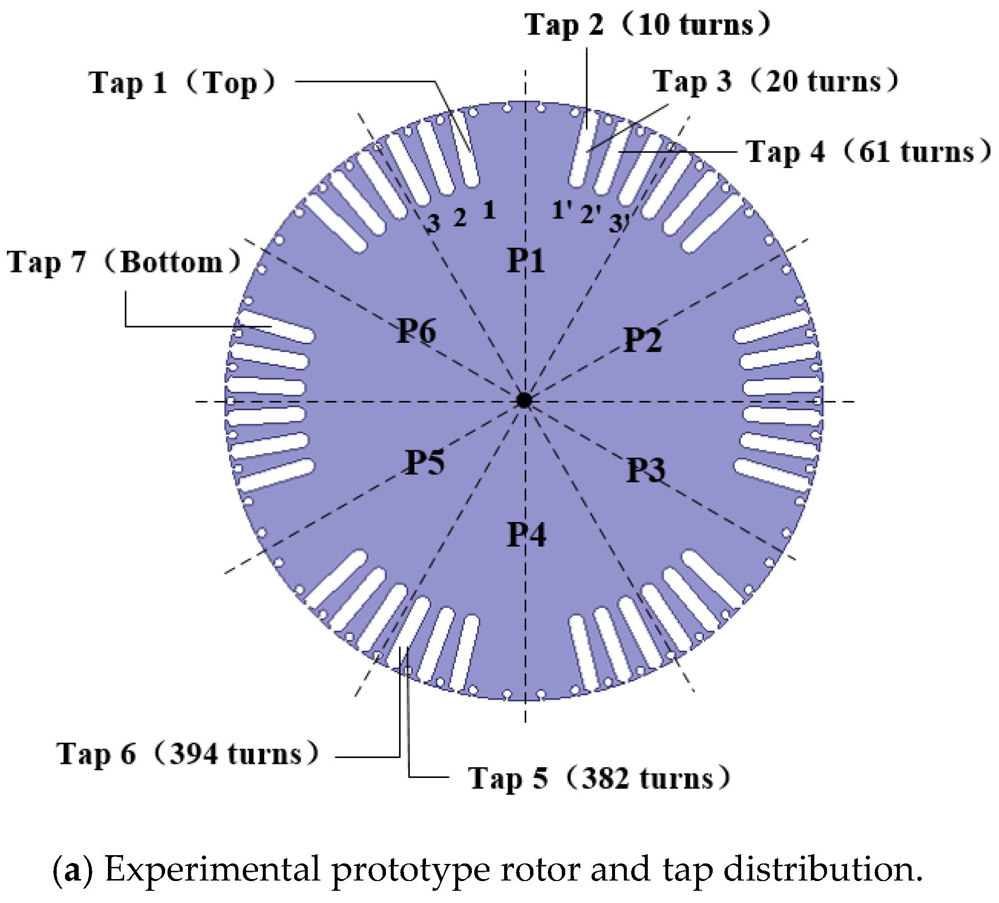
3.1. Analysis on Experimental Prototype

Figure 2 shows the schematic diagram of the A1553 experimental prototype rotor (P = 3). The equal dividing number of radial slots where field windings are located is 54, but to make the spatial distribution of field MMF near to sinusoid, three slots are reduced in the central part of each pole and the actual field slot number is 36. The six slots under each field winding pole are symmetrical about the center line of the magnetic pole, where three concentric coils are placed (taking the first pole of Figure 2 as an example, coils are located in Slot 1 and 1′, Slot 2 and 2′, Slot 3 and 3′, respectively), with the number of series turns for each coil set to 41, so that three coils are in series to form the distributed field winding of each pole. Windings of six poles are in series to form the overall field winding with a number of series turns of 738. Additionally, 54 evenly distributed circular damping slots are opened on rotor surface.
Each phase of stator windings of the experimental prototype is composed of three branches in parallel, which structure is as shown in Figure 3. Branches of each phase are composed of coil assemblies in series-opposing connection. The coil assembly of a1 branch a 1 1 a 1 1 exceeds a 1 2 a 1 2 by π electrical radians and the coil assembly of b1 branch b 1 1 b 1 1 exceeds b 1 2 b 1 2 by π electrical radians, but the coil assembly of c1 branch c 1 1 c 1 1 lags behind c 1 2 c 1 2 by π electrical radians. This can make a unit generator correspond to one branch of each phase and can guarantee the spatial position of each phase of the stator winding is symmetrical to space the fundamental MMF, but it can’t guarantee the symmetry of the fractional harmonic MMF.
From [20], it can be concluded that after an inter-turn short circuit of the rotor occurs, different branches of the same phase of the stator have fractional unbalanced currents, and the order of these unbalanced currents is consistent with the harmonic MMF order: if and only if | μ v | = k 1 , k 1 = 0 , 1 , 2 , , the synthetic MMF only contains forward components; if and only if μ + v = k 2 , k 2 = 1 , 2 , , the synthetic MMF only contains reversed components. There exist more kinds of unbalanced current of stator after faults, and only the harmonic current of frequency near to fundamental frequency is bigger, while the others are relatively smaller. Therefore, only MMF generated by the fundamental current, 1/3-th, 2/3-th and 4/3-th harmonic current is analyzed. The alternating component in field current is far smaller than the direct component. Therefore, only the effect of the direct component is considered here. The MMF generated by the A1553 experimental prototype stator branch current is as shown in Table 1.

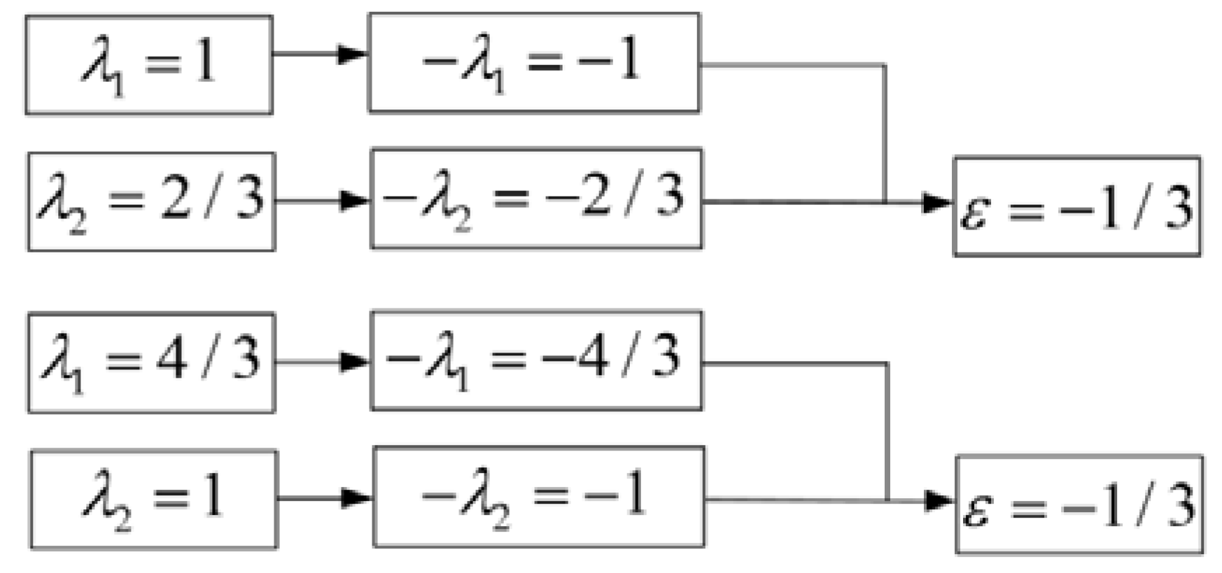
3.1.1. Interaction Results Analysis of Two Different Kinds of Stator Harmonic MMF

As shown in Section 2.3.2, if P v 1 P v 2 1 = 0 or P v 1 P v 2 + 1 = 0 , the electromagnetic force waves with time order of ε = ± μ 1 ( ± μ 2 ) are generated from two different kinds of stator harmonics MMF. The results of interaction for MMF which meet P v 1 P v 2 1 = 0 and P v 1 P v 2 + 1 = 0 are analyzed in Figure 4 and Figure 5, respectively, which show that the fundamental MMF generated by the stator interacts with the 2/3-th and 4/3-th MMF, respectively, to generate i/3-th ( i = 1 , 2 , 4 , ) fractional electromagnetic force waves.

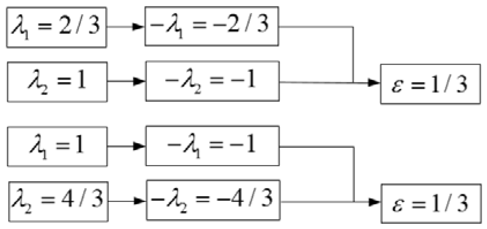
3.1.2. Interaction Result Analysis of Two Different Kinds of Rotor Harmonic MMF

As shown in Section 2.3.2, if P λ 1 P λ 2 1 = 0 or P λ 1 P λ 2 + 1 = 0 , the electromagnetic force waves with time order of ε = λ 1 ( λ 2 ) are generated from two different kinds of rotor harmonics MMF. The results of interaction for MMF which meet P λ 1 P λ 2 1 = 0 and P λ 1 P λ 2 + 1 = 0 are analyzed in Figure 6 and Figure 7, respectively, where it is shown that the fundamental MMF generated by the rotor interacted with the 2/3-th and 4/3-th MMF, respectively, to generate a 1/3-th electromagnetic force wave.

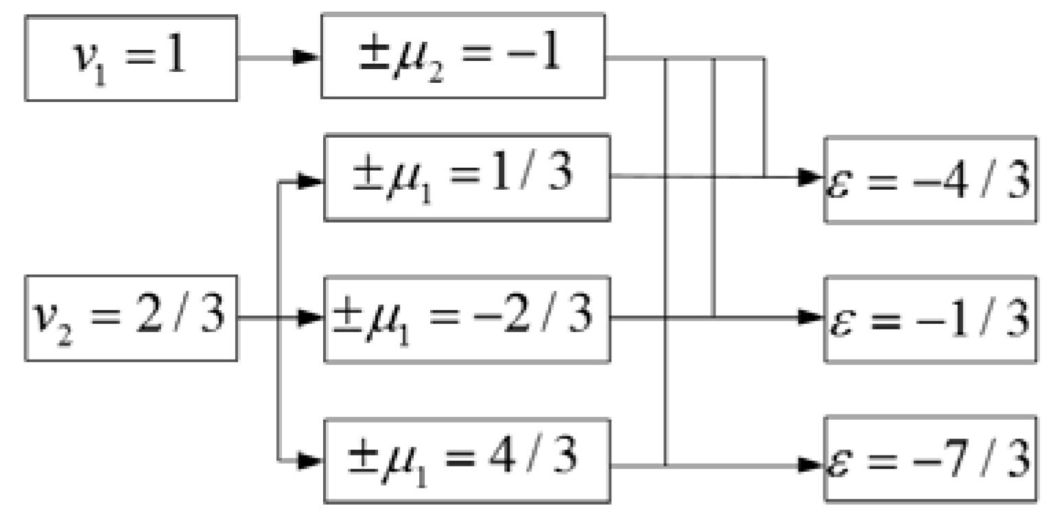
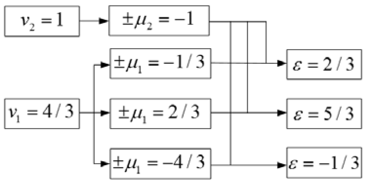
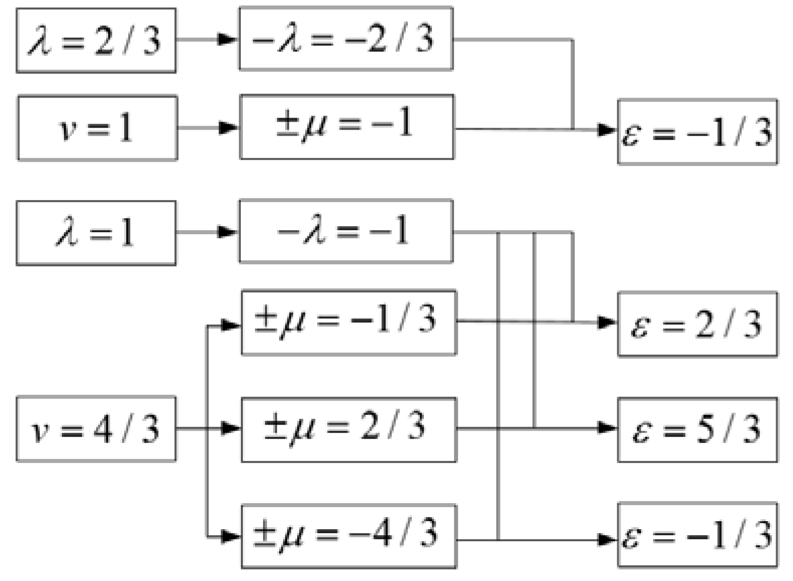
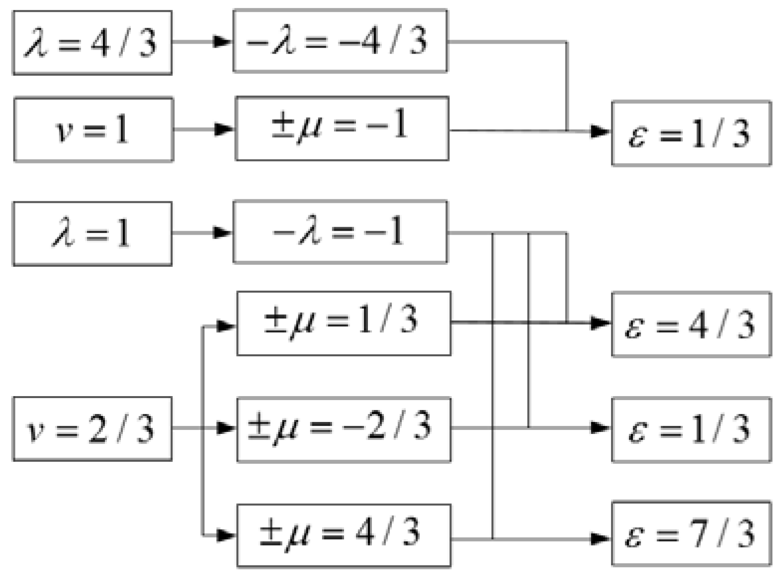
3.1.3. Analysis of Interaction Results of Two Different Kinds of Stator and Rotor Harmonic MMF

As shown in Section 2.3.3, if P v P λ 1 = 0 or P v P λ + 1 = 0 , the electromagnetic force waves with time number of ε = ± μ ( λ ) are generated from two different kinds of stator and rotor harmonics MMF. The results of interaction for MMF as P v P λ 1 = 0 and P v P λ + 1 = 0 are analyzed in Figure 8 and Figure 9, respectively, where it is shown that the two different kinds of harmonic MMF generated by the stator and rotor interacted to generate i/3-th ( i = 1 , 2 , 4 , ) fractional electromagnetic force waves.
From the analysis of Section 3.1.1, Section 3.1.2 and Section 3.1.3, when the A1553 experimental prototype has ISCFW, the rotor is affected by i/3-th ( i = 1 , 2 , 4 , ) fractional electromagnetic force waves along axis x.

3.2. Fault Simulation of Experimental Prototype

Actually, a large-scale generator is generally under networking load operating conditions. Consequently, this section performed simulation calculation on rotor UMP when the experimental prototype A1553 has an inter-turn short circuit of 4–5 taps of field windings under networking operating conditions and implemented FFT analysis on the calculation results of component along the axis x of rotor UMP. The main parameters of the experimental prototype A1553 are as shown in Table 2.
Figure 10 and Figure 11 show respectively the simulation results of rotor UMP of experimental prototype A1553 and FFT analysis results of its component along the axis x. It is clear that the post-fault rotor will be affected by i/3-th ( i = 1 , 2 , 4 , ) fractional electromagnetic force waves in axis x. Therefore the accuracy of our theoretical analysis is verified.

3.3. Analysis on Effect of Stator Winding Forms on Rotor UMP

It is shown from [20] that the stator winding forms have an obvious influence on the harmonic characteristics of unbalanced current of post-fault stator branches. Consequently, it can be concluded that the stator winding form is closely associated with the frequency characteristics of post-fault rotor UMP.

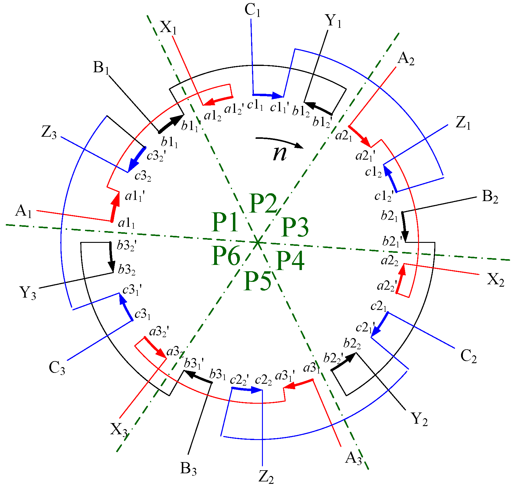
3.3.1. Type A Generator—Stator Winding of Which Spatial Positions Are Fully Symmetrical

A type A generator is obtained by converting the stator windings of the A1553 prototype, making the coil assembly c 1 1 c 1 1 of windings of phase C also exceed c 1 2 c 1 2 by π electrical radians. For such a type of stator winding, the windings of each phase are fully symmetrical in spatial position, and the corresponding branch for each phase has discrepancy of 2π/3 electrical radians in succession. The structure of the Type A generator stator is as shown in Figure 12.
From [21], it can be concluded that the branch current of each phase of Type A generator and its generated harmonic MMF shall meet the following relationships: if and only if | μ v = 3 k 1 | , k 1 = 0 , 1 , 2 , , the three-phase synthetic MMF only contains forward components. If and only if μ + v = 3 k 2 , k 2 = 1 , 2 , , the three-phase synthetic MMF only contains reversed components.
The MMF generated by Type-A generator stator branch current is as shown in Table 3. For the reason that the stator winding form only affects the harmonic characteristics of stator branch unbalanced current, if only considering the direct component of the field current, it will be of no effect on field current. Therefore, the MMF generated by field current is same as that of the prototype.
The method of analysis on the effect of post-fault Type-A generator stator and rotor MMF on rotor UMP is similar to that described in Section 3.1, therefore, it is not described here. The post-fault Type-A generator rotor is mainly affected by 1/3-th, 8/3-th and 10/3-th electromagnetic force waves in axis x.

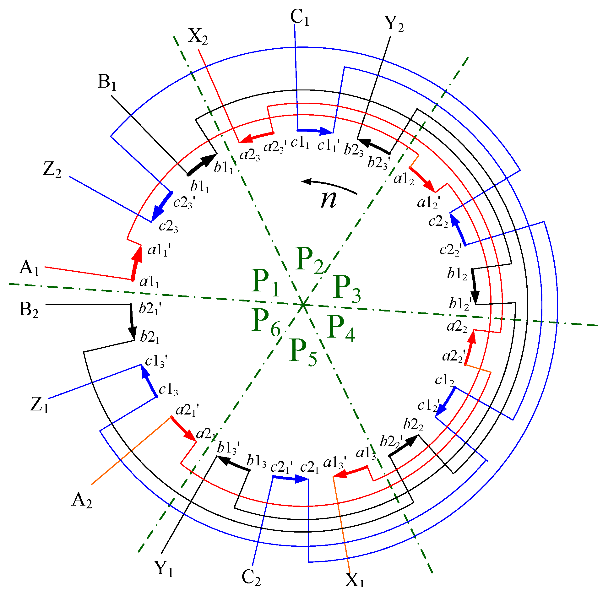
3.3.2. Type B Generator—Stator Winding with Two Branches for Each Phase

The stator winding structure of a Type-B generator is similar to a typical turbine, with two branches for each phase, each phase of which is composed of three coil assemblies in series under the same pole, as is shown in Figure 13.
Taking the winding A as an example, the coil assemblies under P1, P3 and P5 are connected in series to a1 branch, and the coil assemblies under P2, P4 and P6 are connected in series to a2 branch. From [21], it can be concluded that the winding form of a post-fault Type-B generator can eliminate the fractional fault electromotive force, and the stator branch unbalanced current only contains even harmonics. The fault current and its generated harmonic MMF meet the following relationships: if and only if | μ v 1 | = 6 k , k 1 = 0 , 1 , 2 , , the three-phase synthetic MMF only contains forward componenta. If and only if μ + v = 6 k 2 , k 2 = 1 , 2 , , the three-phase synthetic MMF only contains reversed componenta. The MMF generated by a Type-B generator stator branch current is as shown in Table 4.
The analysis process is not described in detail due to limited paper length. It is indicated that the post-fault Type-B generator rotor is mainly affected by 1/3-th electromagnetic force wave in axis x after analysis.

3.4. Fault Simulation of Type A and B Generators

Figure 14, Figure 15, Figure 16 and Figure 17 show the simulation results of rotor UMP of post-fault Type A and B generators, and the FFT analysis results of its component along axis x.
It can be found that a Type A generator rotor is mainly affected by 1/3-th, 8/3-th and 10/3-th electromagnetic force waves in axis x and a Type B generator rotor is mainly affected by 1/3-th electromagnetic force waves in axis x, which is fully consistent with the theoretical analysis results.
Through the above simulation, some conclusions can be obtained as follows:
(a)
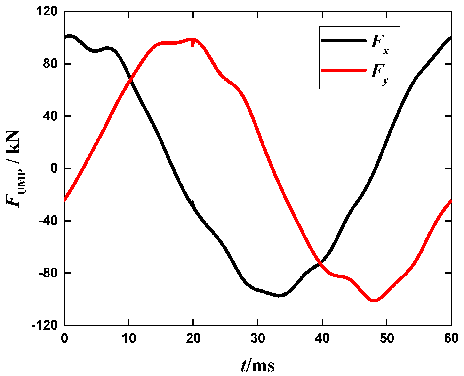
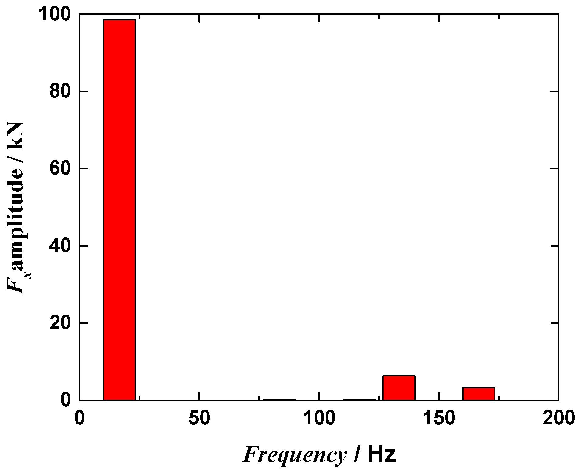
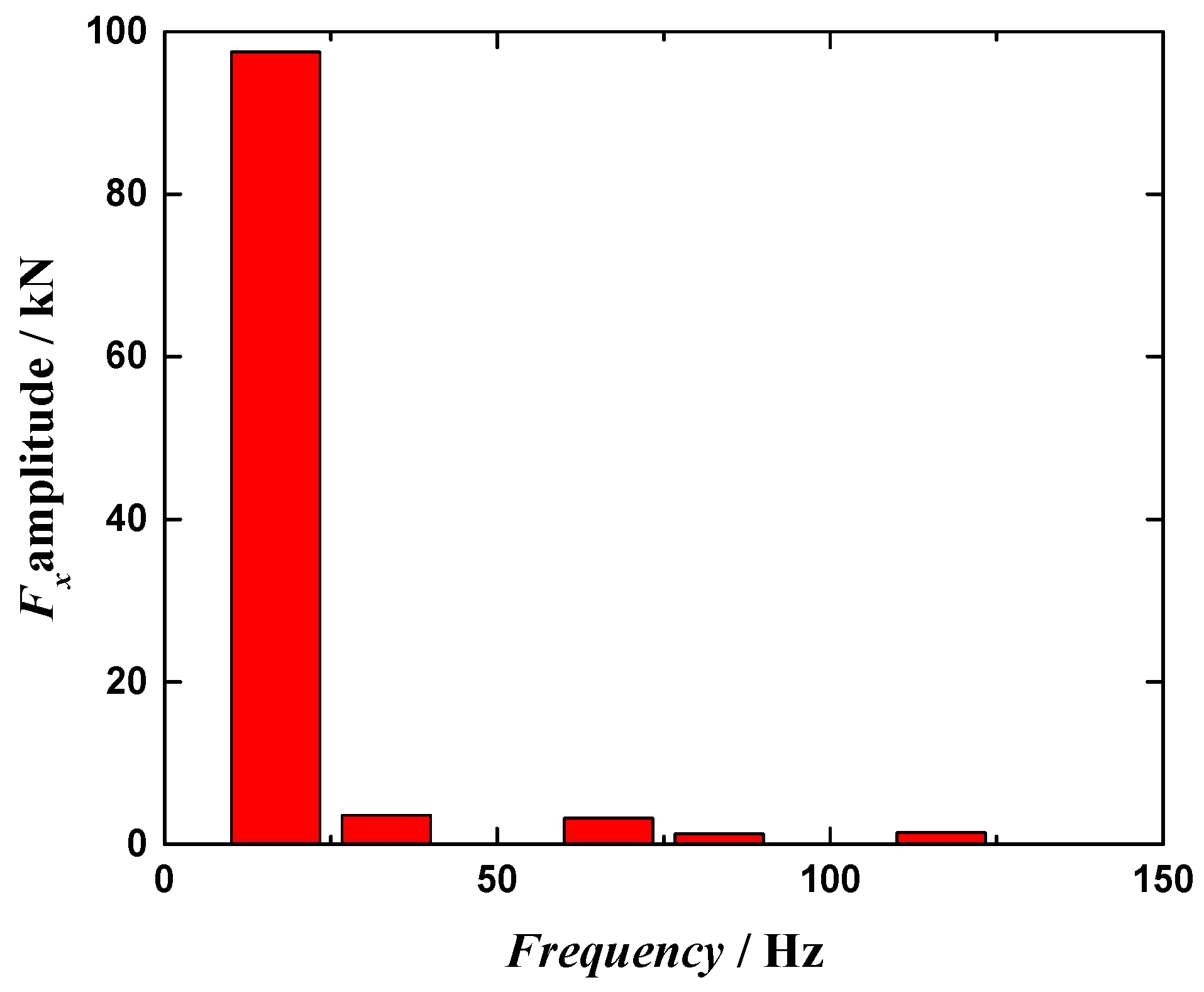
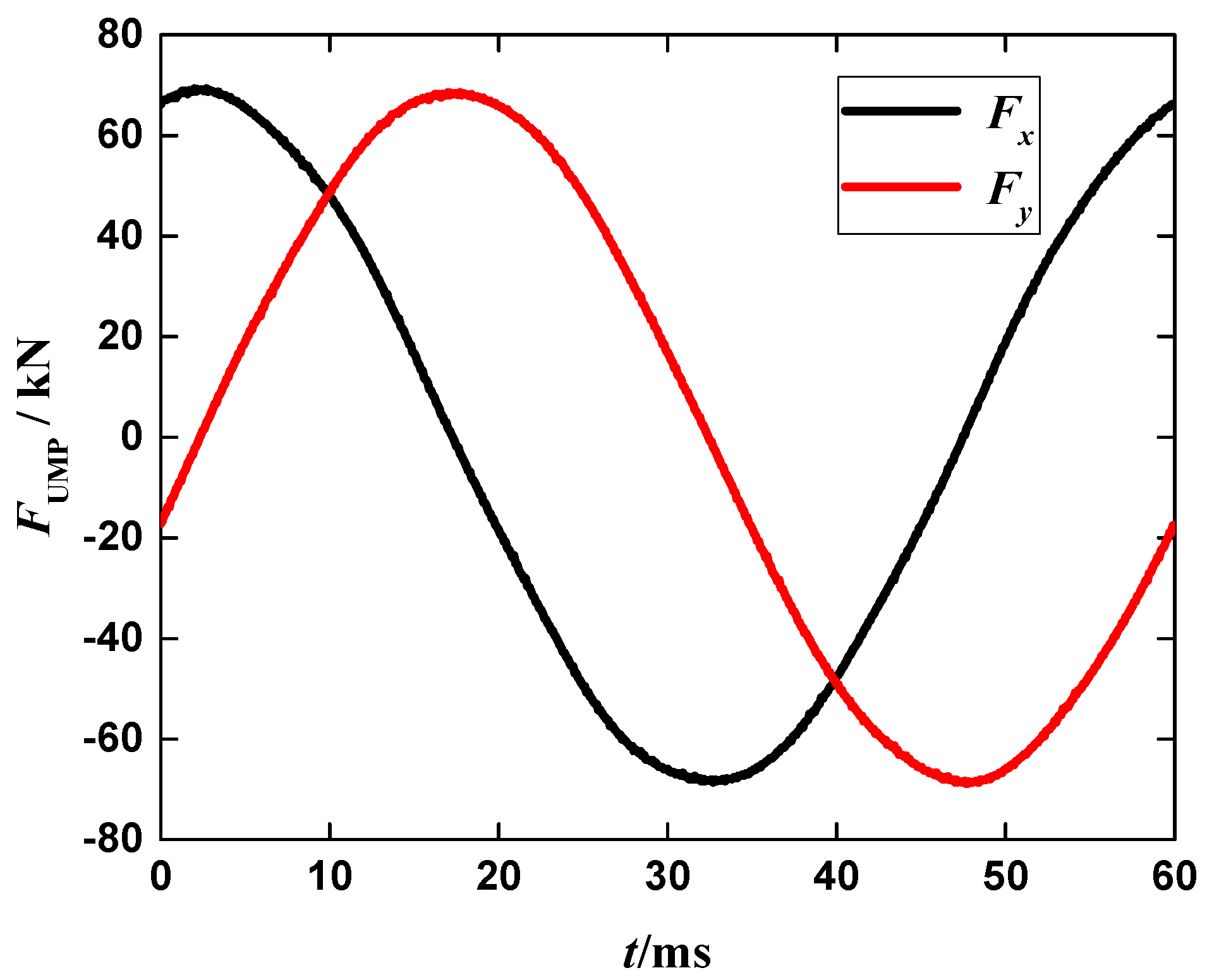
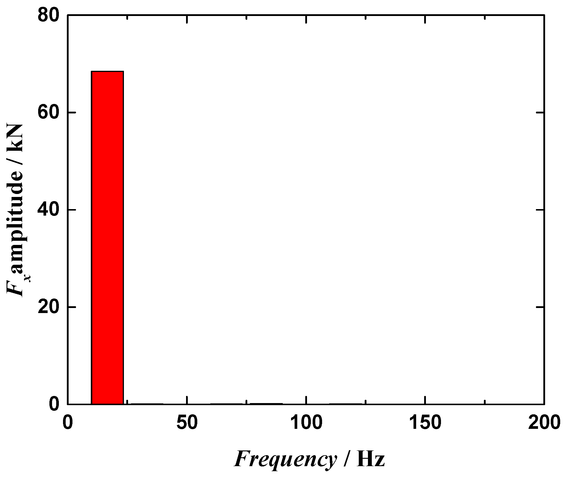
After the ISCFW occurs in a generator, the force waves in rotor UMP with the same mechanical rotation frequency as the rotor are dominant (1/3-th force waves for experimental prototype A1553), while other force waves are relatively less. The main causes are as follows: firstly, the analysis in Section 2.3 indicates that interaction of any two harmonic MMF can generate a 1/3th force wave but won’t generate all higher-order force waves; secondly, the 1/3-th force wave is mainly generated through interactions of the fundamental MMF in the air gap and the 2/3-th and 4/3-th MMF, and these three MMF are relatively bigger compared to other higher-order harmonic MMFs. Therefore, the 1/3-th force wave of post-fault rotor is apparently bigger than other force waves. In a later section, this paper mainly analyzed 1/3-th force waves for amplitude characteristics, without considering the effect of other higher-order force waves.
(b)
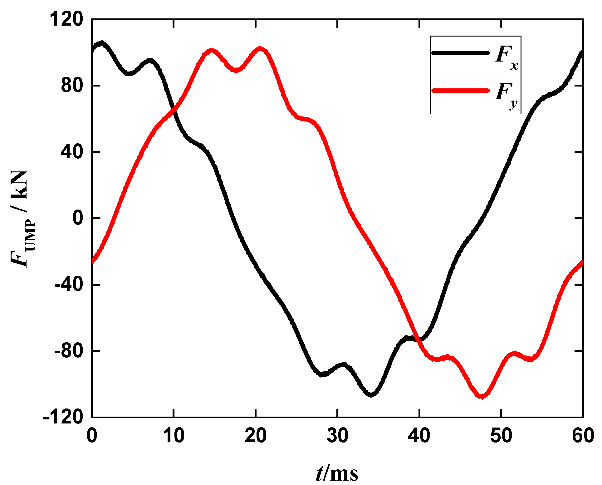
Under the premise that the number of pole pairs is not changed, the stator winding form has an obvious influence on the frequency characteristics of rotor UMP. The main reason is that the change of stator winding form can result in a corresponding change of stator fault current frequency, which comes with the change of its generated harmonic MMF. Therefore, the rotor UMP of generator with different winding forms after fault has different frequency characteristics.

4. Amplitude Characteristics Analysis of Rotor UMP

The amplitude of post-fault rotor UMP is closely associated with harmonic current of stator and rotor, and the change of generator operation conditions can apparently affect rotor currents. Therefore, studying the relationship of rotor UMP amplitude change characteristics and operating conditions change is of great significance.

4.1. Effect of Active Power on Rotor UMP Amplitude

4.1.1. Simulation on Rotor UMP of Generator with Different Active Output Power

In order to study the effect of generator active power on rotor UMP amplitude, the experimental prototype with three winding forms was simulated under different active output powers. In order to exclude the effect of field current on rotor UMP amplitude, the active output power is changed only by changing generator power factor angle during the simulation, while the field current remains constant.
From Table 5 and Figure 18, it can be found that for a generator with three stator winding forms, if the field current is not changed, when the generator active power increases, Fx amplitude will increase, and its change rate will increase too. By comparing three curves of Figure 18, although the generator stator winding form changes, but it only changes the amplitude of rotor UMP whereas it can’t apparently affect the relationship between the rotor UMP amplitude and generator active power.

4.1.2. Analysis of Simulation Results

In order to study the reason why the rotor UMP amplitude varied along with the active power, it is necessary to add all the items together in Section 2.3 that can produce electromagnetic force to obtain an expression of the rotor UMP amplitude. However, the amplitudes and phases of these items are not the same. If they are combined together, the expression of the UMP amplitude will be quite complex, which greatly increases the difficulty of analysis. Therefore, in order to minimize the difficulty, these items shall be properly simplified. In the change process of active power, the field current is always constant. Therefore the harmonic MMF produced by the field current is also constant. For this reason, the items with two kinds of space harmonic MMF for the rotor are not analyzed. For the items with two kinds of space MMF for the stator, although they also have change, the values of them are significantly smaller than the items with space harmonic MMF for the stator and rotor. In order to simplify the calculation, their impacts are also not considered. Hereby, impact of items only with two kinds of space MMF for the stator and rotor on Fx are analyzed. Taking A1553 prototype as an example (The analysis methods of A-type and B-type motors are the same.), the formula of Fx amplitude is as follows:
K x , sr , 1 , 1 , 2 / 3 + K x , sr , 1 , 1 , 4 / 3 = 1 2 F s , 1 , 1 F r , 2 / 3 cos ( 1 3 ω 0 t φ s , 1 , 1 ) + 1 2 F s , 1 , 1 F r , 4 / 3 cos ( 1 3 ω 0 t + φ s , 1 , 1 ) = 1 2 F s , 1 , 1 [ F r , 2 / 3 sin ( φ s , 1 , 1 ) F r , 4 / 3 sin ( φ s , 1 , 1 ) ] 2 + [ F r , 2 / 3 cos ( φ s , 1 , 1 ) + F r , 4 / 3 cos ( φ s , 1 , 1 ) ] 2 sin ( 1 3 ω 0 t + φ 1 ) = 1 2 F s , 1 , 1 F r , 2 / 3 2 + F r , 4 / 3 2 + F r , 2 / 3 F r , 4 / 3 cos ( 2 φ s , 1 , 1 ) sin ( 1 3 ω 0 t + φ 1 ) = F sr , 1 sin ( 1 3 ω 0 t + φ 1 )
F sr , 1 = 1 2 F s , 1 , 1 F r , 2 / 3 2 + F r , 4 / 3 2 + F r , 2 / 3 F r , 4 / 3 cos ( 2 φ s , 1 , 1 )
φ 1 = arctan F r , 2 / 3 cos ( φ s , 1 , 1 ) + F r , 4 / 3 cos ( φ s , 1 , 1 ) F r , 2 / 3 sin ( φ s , 1 , 1 ) F r , 4 / 3 sin ( φ s , 1 , 1 )
From the Equations (13)–(15), it can be seen that the amplitude Fsr,1 of Fx depends on F s , 1 , 1 F r , 2 / 3 2 + F r , 4 / 3 2 + F r , 2 / 3 F r , 4 / 3 cos ( 2 φ s , 1 , 1 ) . As values of F s , 1 , 1 and cos ( 2 φ s , 1 , 1 ) (shown in Table 6) increase along with increasing active power, while F r , 2 / 3 and F r , 4 / 3 maintains constant. Therefore the amplitude of Fx increases with increasing active power.
In the process of active change, the internal power factor angle of the generator is always positive. The generator works in the over-excitation state and the armature current produces a demagnetizing armature reaction. With increasing active power, the demagnetizing armature reaction is stronger and stronger, so the saturation level of the air gap magnetic field is weakened correspondingly. Finally, it results in that the change rate of Fx increases along with increasing active power.
By contrasting the three curves of Figure 19, it can also be found that the rotor UMP value of the A1553 prototype is quite similar to that of an A-type motor with the same active power, but it is quite different from that of a B-type motor. The reason is that the change in the stator winding forms of an A-type motor is very small compared with that of the prototype and it only enables the original asymmetric fractional harmonic MMF to become symmetrical. Each harmonic current of the stator has a little change compared with that of the prototype, so the simulation results of an A-type generator are quite similar to that of the prototype. In contrast, there is a great change in the stator winding forms of a B-type generator. The number of branches per phase and the number of coils per branch are not the same. In addition, as the sum of electromotive force induced by each of branch coil group in the fractional harmonic magnetic field is 0, there is no fractional harmonic current in the stator branch. Therefore a B-type generator stator current has a great gap of the harmonic frequency and amplitude compared with the prototype so as to lead to the fact that there is a relatively large gap of values between the simulation results of a B-type generator and that of the prototype. Although the stator winding form can affect the amplitude characteristics of the stator current, the direction that the stator current changes along with the active power cannot be affected under the premise of constant field current. Therefore, the rotor UMP of generators with three kinds of stator winding forms have different values under the same working conditions, but the directions that their amplitudes change along with the active power are the same.

4.2. Effect of Field Current on the Rotor UMP Amplitude

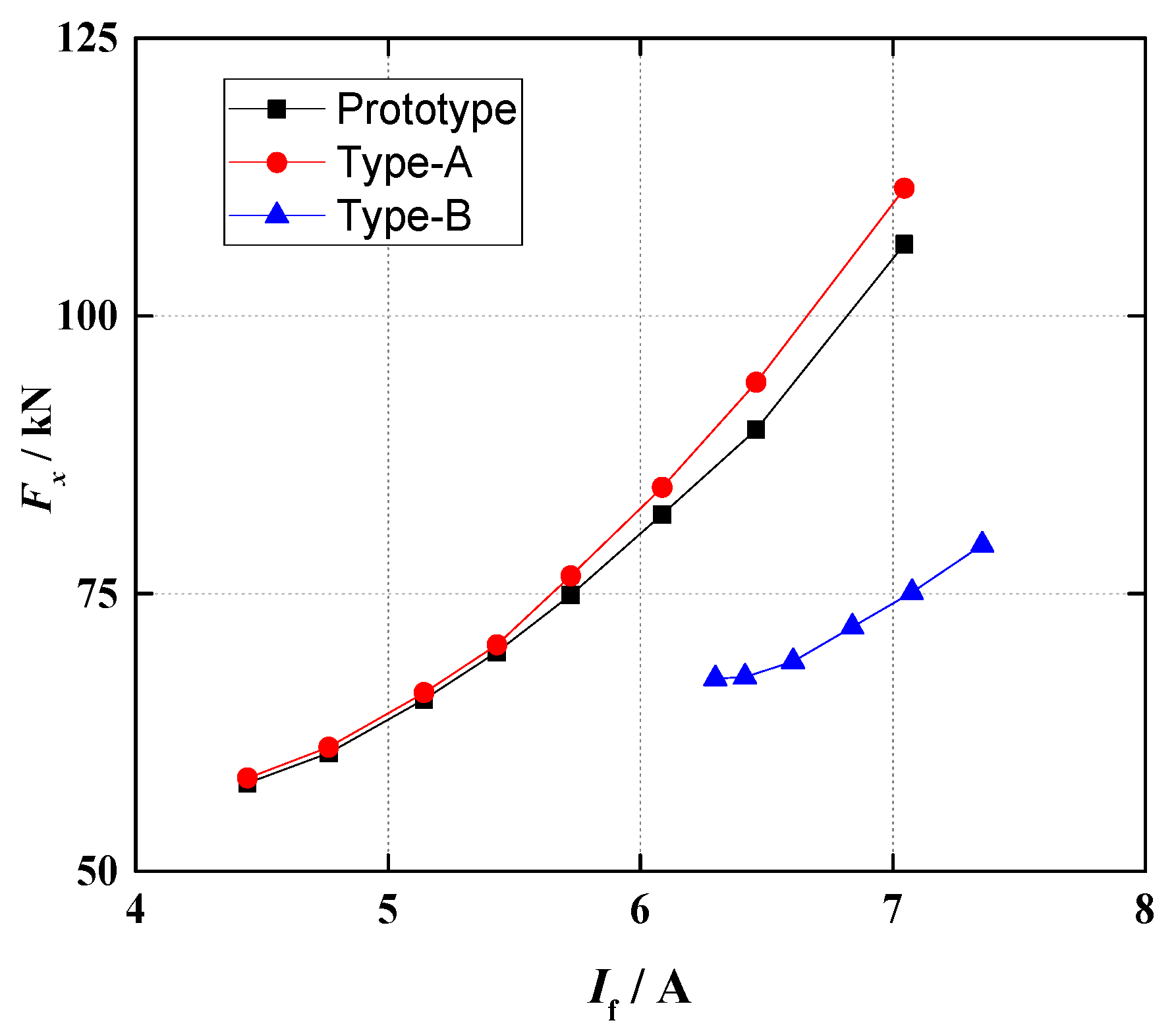
4.2.1. Simulation of the Generator Rotor UMP with Different Field Current

With the same research ideas as Section 4.1, constant active power is maintained by changing the power factor angle of the generator in order to remove the impact of active power on the rotor UMP amplitude. Simulated results of the experimental prototype with different field current are shown in Table 6 and Figure 19.
From Table 5 and Figure 19, it can be found that under the premise of constant active power, Fx amplitude increases along with increasing field current of the generator, and the change rate also increases with it. By contrasting the three curves of Figure 19, it can be found that although the stator winding form changes, it only changes the amplitude of rotor UMP. It has not obvious impact on the relationship between the rotor UMP amplitude and field current of the generator.

4.2.2. Analysis of Simulation Results

In all the harmonic MMF in the air gap for a generator, the fundamental MMF produced by the field current DC component is larger than any other harmonic MMF and its impact on the rotor UMP amplitude is also the most significant. In order to simplify the analysis process, hereby, only the item with fundamental wave field motive force is analyzed. The expression of Fx amplitude is as follows still on the basis of the A1553 prototype:
f x , sr , 2 / 3 , 2 / 3 , 1 + f x , sr , 4 / 3 , 4 / 3 , 1 + f x , r , 1 , 2 / 3 + f x , r , 1 , 4 / 3 = 1 2 F s , 2 / 3 , 2 / 3 F r , 1 cos ( 1 3 ω 0 t + φ s , 2 / 3 , 2 / 3 ) + 1 2 F s , 4 / 3 , 4 / 3 F r , 1 cos ( 1 3 ω 0 t φ s , 4 / 3 , 4 / 3 ) + 1 2 F r , 1 F r , 2 / 3 cos ( 1 3 ω 0 t ) + 1 2 F r , 1 F r , 4 / 3 cos ( 1 3 ω 0 t ) = 1 2 F r , 1 { [ F s , 2 / 3 , 2 / 3 cos ( φ s , 2 / 3 , 2 / 3 ) + F s , 4 / 3 , 4 / 3 cos ( φ s , 4 / 3 , 4 / 3 ) + F r , 2 / 3 + F r , 4 / 3 ] cos ( 1 3 ω 0 t ) + [ F s , 2 / 3 , 2 / 3 sin ( φ s , 2 / 3 , 2 / 3 ) + F s , 4 / 3 , 4 / 3 sin ( φ s , 4 / 3 , 4 / 3 ) ] sin ( 1 3 ω 0 t ) = 1 2 F r , 1 [ F s , 2 / 3 , 2 / 3 cos ( φ s , 2 / 3 , 2 / 3 ) + F s , 4 / 3 , 4 / 3 cos ( φ s , 4 / 3 , 4 / 3 ) + F r , 2 / 3 + F r , 4 / 3 ] 2 + [ F s , 2 / 3 , 2 / 3 sin ( φ s , 2 / 3 , 2 / 3 ) F s , 4 / 3 , 4 / 3 sin ( φ s , 4 / 3 , 4 / 3 ) ] 2 sin ( 1 3 ω 0 t + φ 2 ) = F sr , 2 sin ( 1 3 ω 0 t + φ 2 )
F sr , 2 = 1 2 F r , 1 [ F s , 2 / 3 , 2 / 3 cos ( φ s , 2 / 3 , 2 / 3 ) + F s , 4 / 3 , 4 / 3 cos ( φ s , 4 / 3 , 4 / 3 ) + F r , 2 / 3 + F r , 4 / 3 ] 2 + [ F s , 2 / 3 , 2 / 3 sin ( φ s , 2 / 3 , 2 / 3 ) F s , 4 / 3 , 4 / 3 sin ( φ s , 4 / 3 , 4 / 3 ) ] 2
φ 2 = arctan F s , 2 / 3 , 2 / 3 cos ( φ s , 2 / 3 , 2 / 3 ) + F s , 4 / 3 , 4 / 3 cos ( φ s , 4 / 3 , 4 / 3 ) + F r , 2 / 3 + F r , 4 / 3 F s , 2 / 3 , 2 / 3 sin ( φ s , 2 / 3 , 2 / 3 ) + F s , 4 / 3 , 4 / 3 sin ( φ s , 4 / 3 , 4 / 3 )
Although the stator current of the generator changes, such changes are only limited to amplitudes of each harmonic current (fundamental current is an exception) and the phase has not any obvious change. Therefore, φ s , 2 / 3 , 2 / 3 and φ s , 4 / 3 , 4 / 3 in Equation (16) are always constants in the field current change process. As the 2/3-th and 4/3-th harmonic current in the stator branch are produced by the 2/3-th and 4/3-th MMF generated by the DC component of the rotor field current, both of F s , 2 / 3 , 2 / 3 and F s , 4 / 3 , 4 / 3 are proportional to F r , 2 / 3 and F r , 4 / 3 . Then, F s , 2 / 3 , 2 / 3 , F s , 4 / 3 , 4 / 3 , F r , 2 / 3 , F r , 4 / 3 and F r , 1 in the above equation are proportional to the DC component of the field current after failure, so the value of F sr , 2 should be proportional to the square of the field current DC component, namely F sr , 2 I f 2 . However, only four items which have a great impact on UMP amplitude are analyzed in Equation (16). Other items with relatively less impact cannot influence the relationship between the rotor UMP and field current, but not all the amplitudes of the items are proportional to the square of field current DC component. For example, the item in Equation (16) with fundamental wave MMF and 2/3-th MMF produced by the rotor, is not analyzed for its small value, and its amplitude is proportional to the product of the rotor fundamental wave current and field current component. Such items will influence the change rate of rotor UMP amplitude along with changing field current. Therefore, under the premise of constant active power, the rotor UMP amplitude increases along with increasing field current of the generator, but strictly it is not proportional to the square of field current DC component.
From the simulation results of Section 4.1 and Section 4.2, the amplitude of the generator rotor UMP increases along with increasing active power and field current after failure and the increasing speed is faster and faster, which are the variation characteristics of a rotor UMP in fault. In industry application, if the amplitude variation of the generator rotor is consistent with the change of active power and excitation current, it is considered that the generator may have a ISCFW fault. However, this still requires a further study on the vibration response of the rotor after failure. Based on this study, the electromechanically fused online fault monitoring can be achieved. First, the vibration characteristics of the rotor are used as an auxiliary criterion, and by combination with the developed method based on the electrical quantities, the fault monitoring is more accurate. Second, the relationship between UMP amplitude and working conditions after a fault is obtained and based on that, we can further study the vibration response characteristics with different electrical quantities and find the relationship between the vibration response and electrical quantities. From this level, the fusion of mechanical and electrical features of the fault can be achieved. This paper lays a foundation for the calculation of the rotor vibration responses caused by faults and the study of online fault monitoring schemes based on the fusion of electrical and mechanical features.

5. Conclusions

In this paper, the influence mechanism of several factors on UMP is revealed through in-depth and detailed analysis of the fault magnetic fields. Taking the A1553 experimental prototype with three different stator winding forms as an example, theoretical analysis and simulative calculation on amplitude and frequency characteristics of the generator rotor UMP with ISCFW are made and the following conclusions are obtained:
(1)
After ISCFW, the force wave in the generator rotor UMP which has the same frequency as that of the rotor mechanical rotation, is the main component, and other harmonic waves are relatively small. The change of stator winding form will cause the variation of air gap harmonic MMF so as to have a significant effect on frequency characteristics of the rotor UMP.
(2)
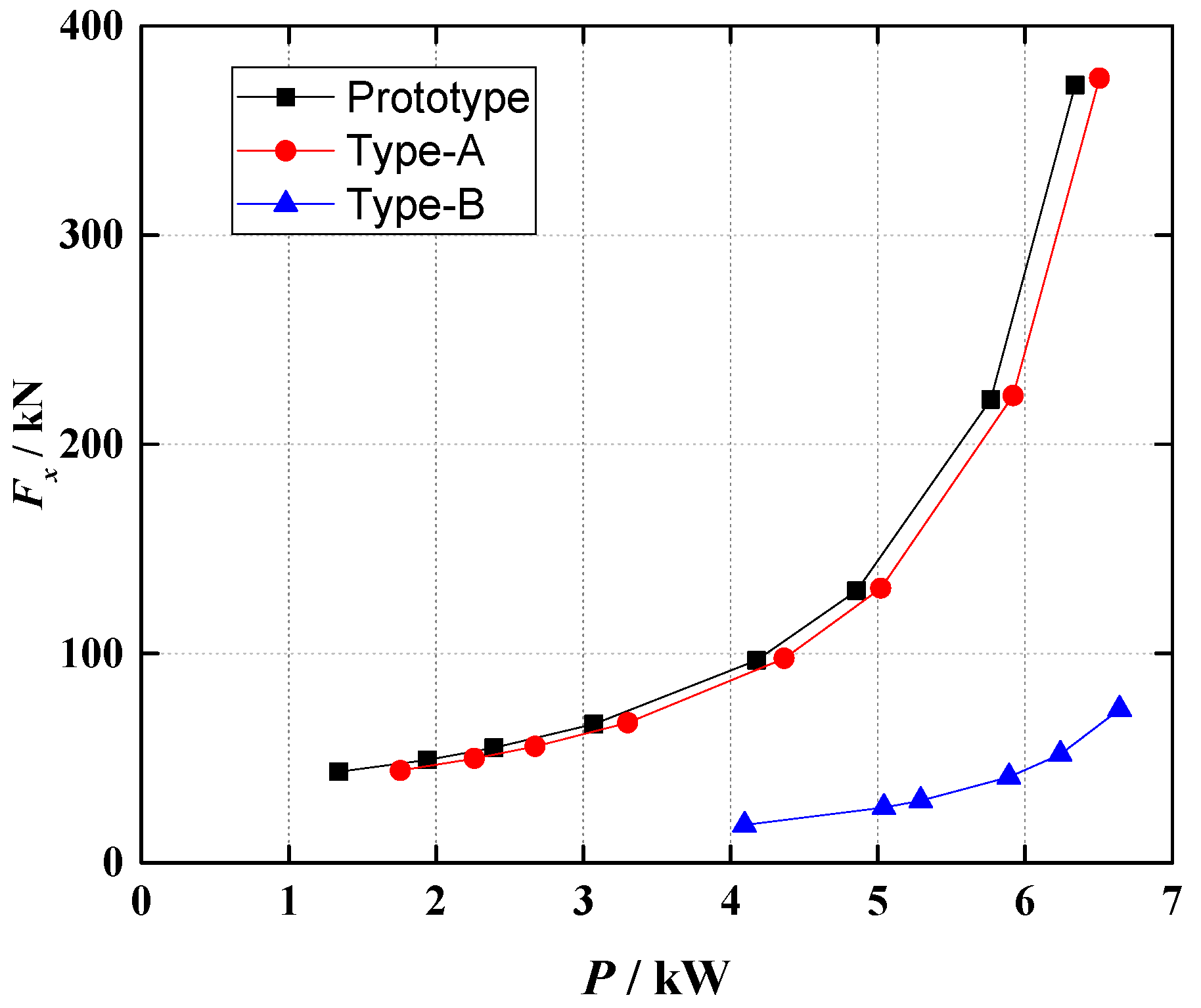
Under the premise of constant field current, the amplitude and change rate of the generator rotor UMP increases along with increasing active power; on the basis of constant active power, the amplitude and change rate of the generator rotor UMP also increase along with increasing field current. The stator winding form only affects the amplitudes of the rotor UMP after a fault, but has no obvious effect on the relationship between amplitudes and working conditions of the generator.
This paper studies the amplitude and frequency characteristics of rotor UMP of a multi-pole synchronous generator with ISCFW, obtains the relationship between UMP amplitude and working conditions after failure, and lays a solid foundation for fault monitoring based on the integration of mechanical and electronic information so as to improve the detection sensitivity further. The next step is to analyze the characteristics of vibration responses and to develop a method to detect the ISCFW using vibration and electronic characteristics.

Acknowledgments

This work presented in this paper was supported by the National Natural Science Foundation of China (No. 51307005) and the Fundamental Research Funds for the Central Universities (No. 2017JBM059).

Author Contributions

All authors made significant contributions to this research. More specifically, Guangtao Zhang built the simulation model, analyzed the simulation results and wrote the paper. Liangliang Hao designed the methodology and revised the paper. Junyong Wu provided important comments on the paper’s structure.

Conflicts of Interest

The authors declare no conflicts of interest.

References

  1. Li, Y.G.; Zhao, H.; Li, H.M. The new method on rotor winding inter turn short-circuit fault measure of turbine generator. In Proceedings of the 2003 IEEE International Electric Machines and Drives Conference, Madison, WI, USA, 1–4 June 2003; pp. 1483–1487. [Google Scholar]
  2. Hao, L.L.; Wu, J.Y.; Zhou, Y.Z. Theoretical Analysis and Calculation Model of the Electromagnetic Torque of Non-salient Pole Synchronous Machines with Inter-turn Short Circuit in Field Windings. IEEE Trans. Energy Convers. 2015, 30, 110–121. [Google Scholar] [CrossRef]
  3. Faiz, J.; Moosavi, S.M.M.; Abadi, M.B.; Cruz, S.M.A. Magnetic equivalent circuit modelling of doubly-fed induction generator with assessment of rotor inter-turn short-circuit fault indices. IET Renew. Power Gener. 2016, 10, 1431–1440. [Google Scholar] [CrossRef]
  4. Naderi, P.; Shiri, A. Rotor/Stator Inter-Turn Short Circuit Fault Detection for Saturable Wound-Rotor Induction Machine by Modified Magnetic Equivalent Circuit Approach. IEEE Trans. Magn. 2017, 53. [Google Scholar] [CrossRef]
  5. Jawad, F.; Mehran, K.; Mahmud, G.; Sérgio, M. Impacts of rotor inter-turn short circuit fault upon performance of wound rotor induction machines. Electr. Power Syst. Res. 2016, 135, 48–58. [Google Scholar]
  6. Yuan, Q.; Mohsen, Z.; Bilal, A.; Stephen, E. Analysis and Detection of Inter-Turn Short-Circut Fault through Extended Self-Commissioning. IEEE Trans. Ind. Appl. 2017, 53, 2730–2739. [Google Scholar]
  7. Ramirez-Nino, J.; Pascacio, A. Detecting inter-turn short circuits in rotor windings. IEEE Comput. Appl. Power 2001, 14, 39–42. [Google Scholar] [CrossRef]
  8. Fiser, R.; Makuc, D.; Lavriě, H.; Miljavec, D.; Bugeza, M. Modeling, analysis and detection of rotor field winding faults in synchronous generators. In Proceedings of the 19th International Conference on Electrical Machines, Rome, Italy, 6–8 September 2010; pp. 1–6. [Google Scholar]
  9. Guttormsson, S.E.; Marks, R.J.; Ei-Sharkawi, M.A. Elliptical novelty grouping for on-line short-turn detection of excited running rotors. IEEE Trans. Energy Convers. 1999, 14, 16–22. [Google Scholar] [CrossRef]
  10. Kulkarni, A.S.; Ei-Sharkawi, M.; Marks, R.J. Development of a technique for on-line detection of shorts infield windings of turbine-generator rotors circuit design and testing. IEEE Trans. Energy Convers. 2000, 15, 8–13. [Google Scholar]
  11. Hao, L.L.; Sun, Y.G.; Qiu, A.R.; Wang, X.H. Steady-State Calculation and Online Monitoring of Inter-turn Short Circuit of Field Windings in Synchronous Machines. IEEE Trans. Energy Convers. 2012, 27, 128–138. [Google Scholar] [CrossRef]
  12. Neti, P.; Nandi, S. Analysis and modeling of a synchronous machine with structural asymmetries. In Proceedings of the 2006 IEEE Conference on Electrical and Computer Engineering, Ottawa, ON, Canada, 7–10 May 2006; pp. 1236–1239. [Google Scholar]
  13. Hao, L.L.; Sun, Y.G.; Qiu, A.R. Monitoring of field winding inter-turn short circuit based on unbalanced current effective value in main protection. Autom. Electr. Power Syst. 2011, 35, 83–87. [Google Scholar]
  14. Sun, Y.G.; Wang, B.H.; Xu, W.; Jiang, C.S. Online monitoring of excitation winding inter-turn short circuit of generator/motor. Electr. Power Autom. Equip. 2017, 37, 211–217. [Google Scholar]
  15. Zhang, Z.P.; Liu, S. On-line diagnosis of inter-turn short circuit for large turbine generator’s rotor. Electr. Power Autom. Equip. 2012, 32, 148–152. [Google Scholar]
  16. He, Y.L.; Ke, M.Q.; Wang, F.L.; Tang, G.J.; Wan, S.T. Effect of Static Eccentricity and Stator Inter-Turn Short Circuit Composite Fault on Rotor Vibration Characteristics of Generator. Trans. Can. Soc. Mech. Eng. 2015, 39, 767–781. [Google Scholar]
  17. Zhang, G.Y.; Wei, J.C.; Huang, H.Z.; Zhou, M. A study on the nonlinear vibration of the generator rotor based on the unbalanced electromagnetic force and the oil film force coupling model. J. Vibroeng. 2013, 15, 23–26. [Google Scholar]
  18. Wu, Y.C.; Li, Y.G.; Feng, W.Z.; Zhang, W.J. Analysis on unbalanced magnetic pull generated by turn-to-turn short circuit of rotor windings within turbine generator. Electr. Mach. Control 2015, 19, 37–44. [Google Scholar]
  19. Zhang, G.T.; Wu, J.Y.; Hao, L.L. Fast Calculation Model and Theoretical Analysis of Rotor Unbalanced Magnetic Pull for Inter-Turn Short Circuit of Field Windings of Non-Salient Pole Generators. Energies 2017, 10, 732. [Google Scholar] [CrossRef]
  20. Hao, L.L.; Sun, Y.G.; Qiu, A.R.; Wang, X.H. Effects of Stator Winding Configurations on Steady-state Currents Characteristics of Synchronous Generator with Inter-turn Short Circuits of Field Windings. Proc. CSEE 2011, 31, 61–68. [Google Scholar]
  21. Li, Y.; Hao, L.L.; Sun, Y.G. The Analysis of UMP Caused by Non-salient Pole Synchronous Generator Rotor Winding Inter-turn Short Circuit Fault. Autom. Electr. Power Syst. 2016, 40, 81–89. [Google Scholar]
Figure 1. Space Vector Disintegration Figure of Radial Electromagnetic Density fr.
Energies 11 00060 g001
Figure 2. Schematic Diagram of the A1553 Experimental Prototype Rotor.
Energies 11 00060 g002aEnergies 11 00060 g002b
Figure 3. Schematic Diagram of the A1553 Experimental Prototype Stator.
Energies 11 00060 g003
Figure 4. Force Wave generated by Stator MMF when P v 1 P v 2 1 = 0 .
Energies 11 00060 g004
Figure 5. Force Wave generated by Stator MMF when P v 1 P v 2 + 1 = 0 .
Energies 11 00060 g005
Figure 6. Force Wave generated by the Rotor MMF when P λ 1 P λ 2 1 = 0 .
Energies 11 00060 g006
Figure 7. Force Wave generated by the Rotor MMF when P λ 1 P λ 2 + 1 = 0 .
Energies 11 00060 g007
Figure 8. Force Wave generated by MMF of the Stator and Rotor when P v P λ 1 = 0 .
Energies 11 00060 g008
Figure 9. Force Wave generated by MMF of the Stator and Rotor when P v P λ + 1 = 0 .
Energies 11 00060 g009
Figure 10. Simulation Results of the Rotor UMP of the A1553 Prototype.
Energies 11 00060 g010
Figure 11. FFT Analysis Results of the Rotor UMP of the A1553 Prototype.
Energies 11 00060 g011
Figure 12. Schematic Diagram of the Stator Structure of a Type A Generator.
Energies 11 00060 g012
Figure 13. Schematic Diagram of the Stator Structure of a Type-B Generator.
Energies 11 00060 g013
Figure 14. Simulation Results of Rotor UMP of a Type A Generator.
Energies 11 00060 g014
Figure 15. FFT Analysis Results of Rotor UMP of a Type A Generator.
Energies 11 00060 g015
Figure 16. Simulation Results of Rotor UMP of a Type B Generator.
Energies 11 00060 g016
Figure 17. FFT Analysis Results of Rotor UMP of a Type B Generator.
Energies 11 00060 g017
Figure 18. Relationship of Rotor UMP of the A1553 model machine with three types of stator winding form and active power.
Energies 11 00060 g018
Figure 19. Relationship of Rotor UMP of the A1553 model machine with three types of stator winding form and field current.
Energies 11 00060 g019
Table 1. MMF Generated by A1553 Stator Harmonic Current.
Order of Harmonics of Stator Branch μNumber of Space Rotation MMF ν
Rotate ClockwiseRotate Anticlockwise
1/31/3,4/32/3,5/3
2/32/3,5/31/3,4/3
11-
4/31/3,4/32/3,5/3
Table 2. Main Parameters of the Experimental Prototype A1553.
Rated power PN = 12 kW;Rated power factor cosφN = 0.8 (lagged)
Rated voltage UN = 400 V(Y);Rated frequency fN = 50 Hz;
Air gap length δ = 1.5 mmNumber of pole pairs P = 3
Rated field current IfdN = 16 ARated speed nN = 1000 r/min
Slot number of stator Z = 72Coil pitch of stator ys = 10 (number of slots)
Slot number of stator for each pole and each phase q = 4Number of parallel branches for each phase of stator a = 3
Number of series turns for each pole of field winding is 123Number of parallel branches for field winding is 1
Table 3. MMF Generated by Stator Branch Current of a Type A Generator.
Number of Stator Branch Harmonics μNumber of Spatial Rotation MMF ν
Rotate ClockwiseRotate Anticlockwise
1/31/38/3
2/32/37/3
11-
4/34/35/3
Table 4. MMF Generated by Type-B Generator Stator Branch Current.
Number of Stator Branch Harmonics μNumber of Spatial Rotation MMF ν
Rotate ClockwiseRotate Anticlockwise
11-
224
442
Table 5. Simulation Results of Rotor UMP of the A1553 Prototype under Different Active Power.
a3 Fundamental Current (A) cos ( 2 φ s , 1 , 1 ) If (A)Active Power (kW)Fx (kN)
6.590.996.696.34371.82
6.020.966.695.77221.38
5.110.726.694.86129.93
4.440.456.694.1896.66
3.38−0.096.693.0766.22
2.75−0.486.692.3954.90
2.36−0.736.691.9449.17
1.88−0.986.691.3443.43
Table 6. Simulation Results for Rotor UMP of the A1553 Prototype with Different Field Currents.
Field Current (A)Active Power (kW)UMP (kN)
7.054.24106.45
6.464.2489.78
6.094.2482.12
5.734.2475.83
5.434.2469.73
5.144.2465.48
4.774.2460.65
4.444.2457.93

