Performance Investigation and Optimization of a Novel Hybrid Saturated-Core Fault-Current Limiter Considering the Leakage Effect

 , ,
, ,
Abstract
:1. Introduction
2. Fundamental Principle and Magnetic Circuit Model of the HSCFCL
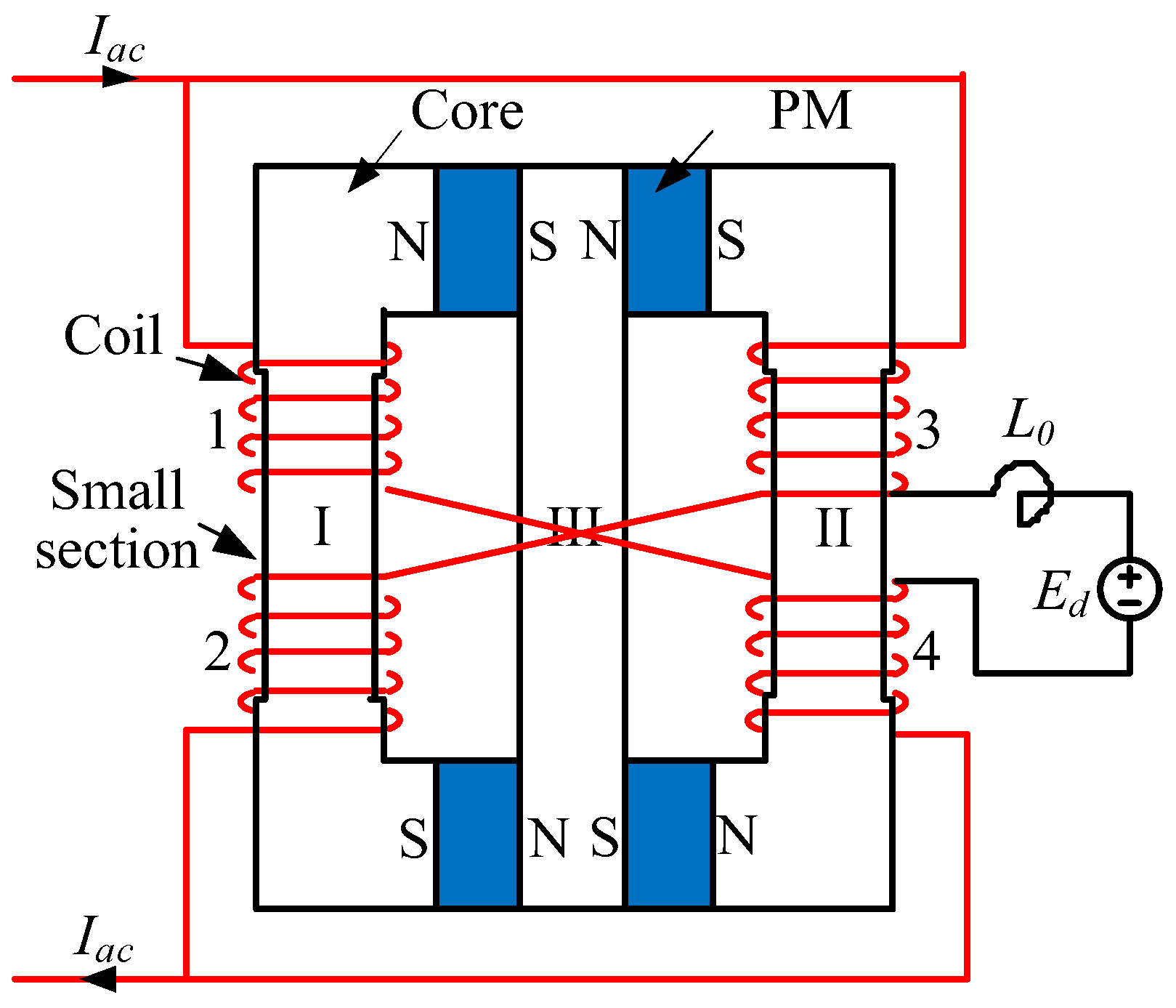
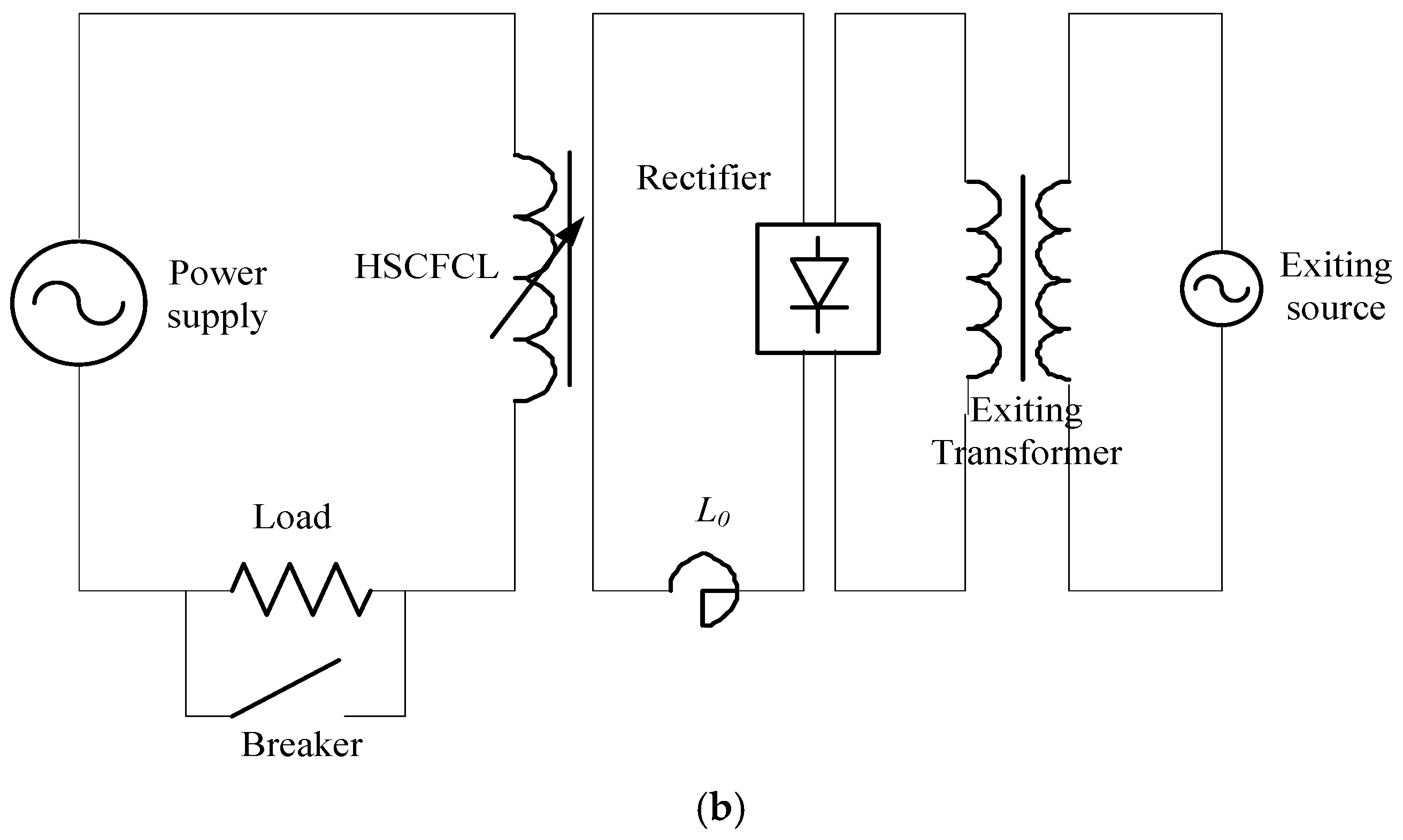
2.1. Basic Configuration of the HSCFCL
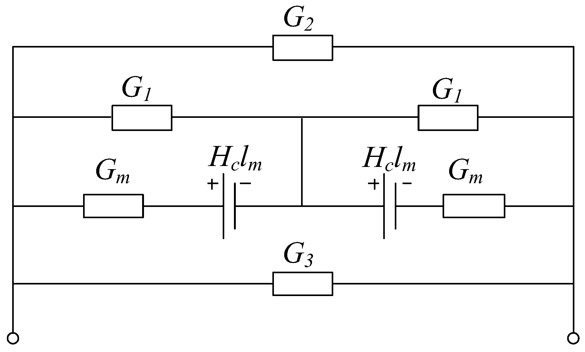
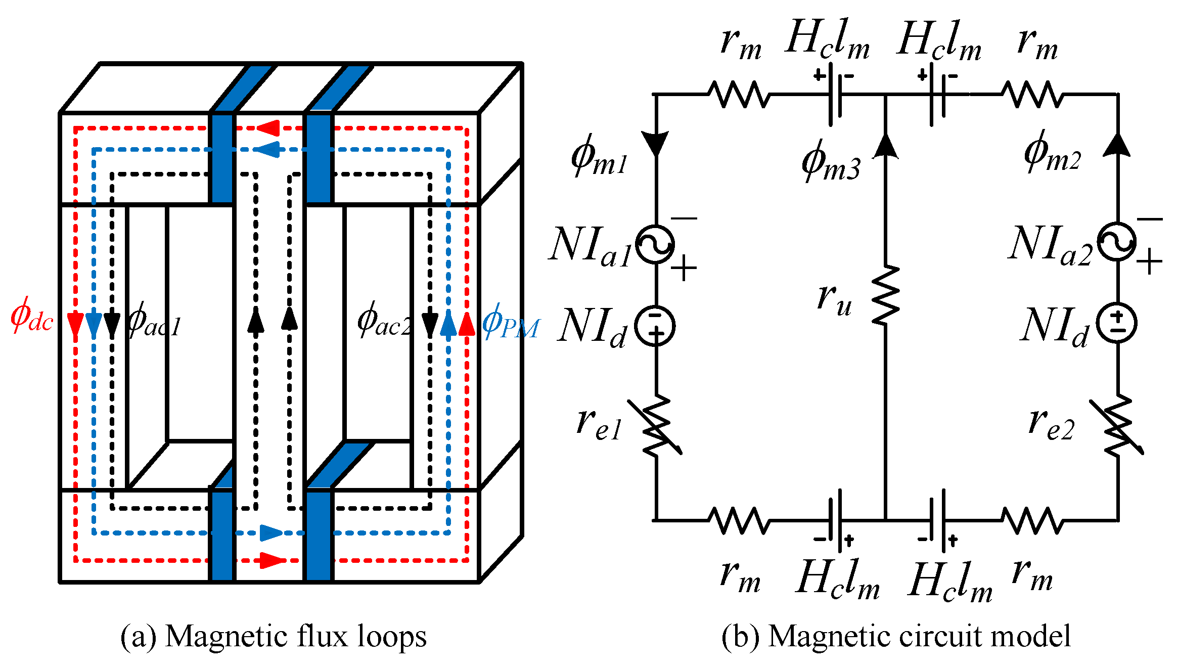
2.2. Magnetic Circuit Modeling
2.3. Improvement of DC-Biasing Capacity with PMs
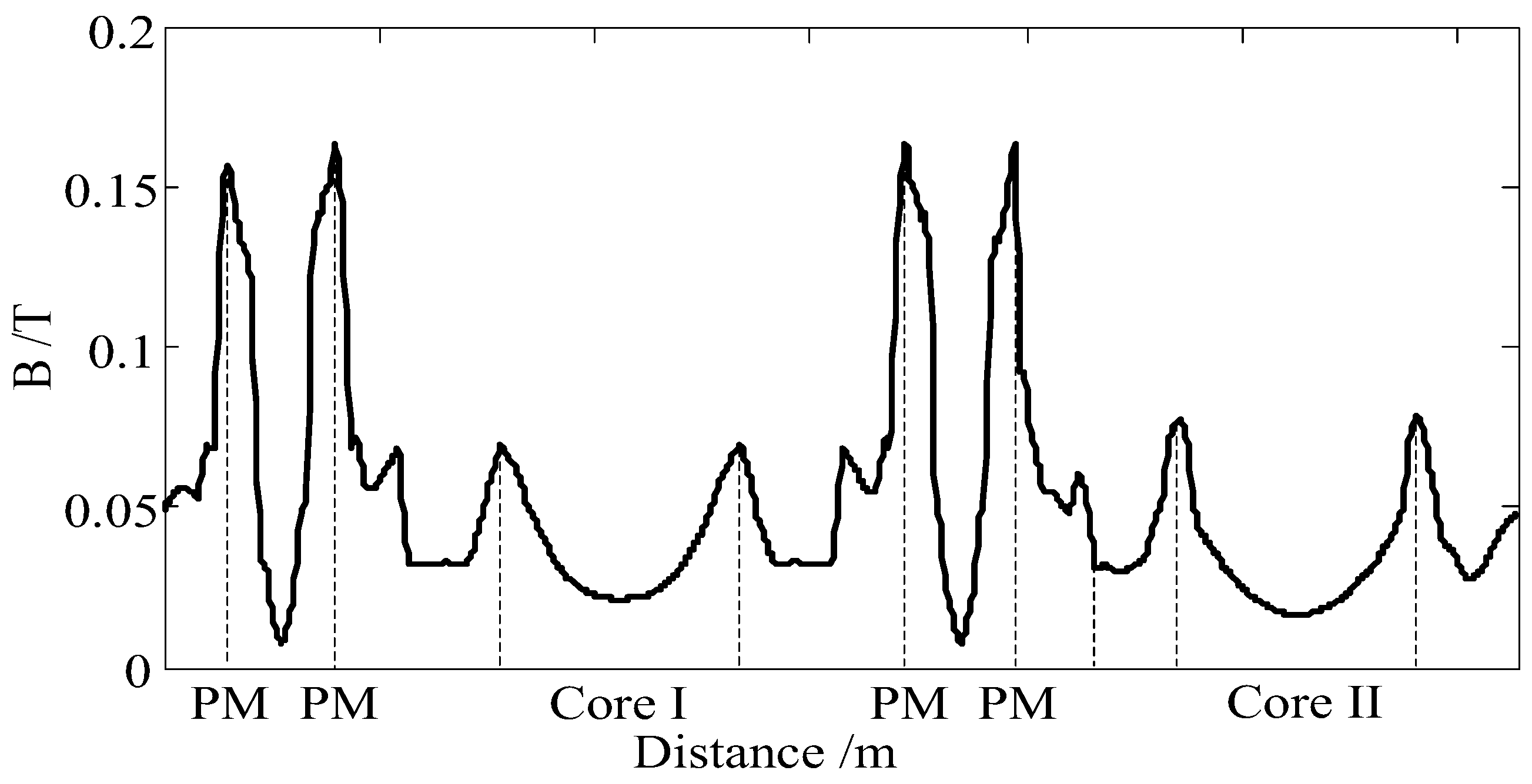
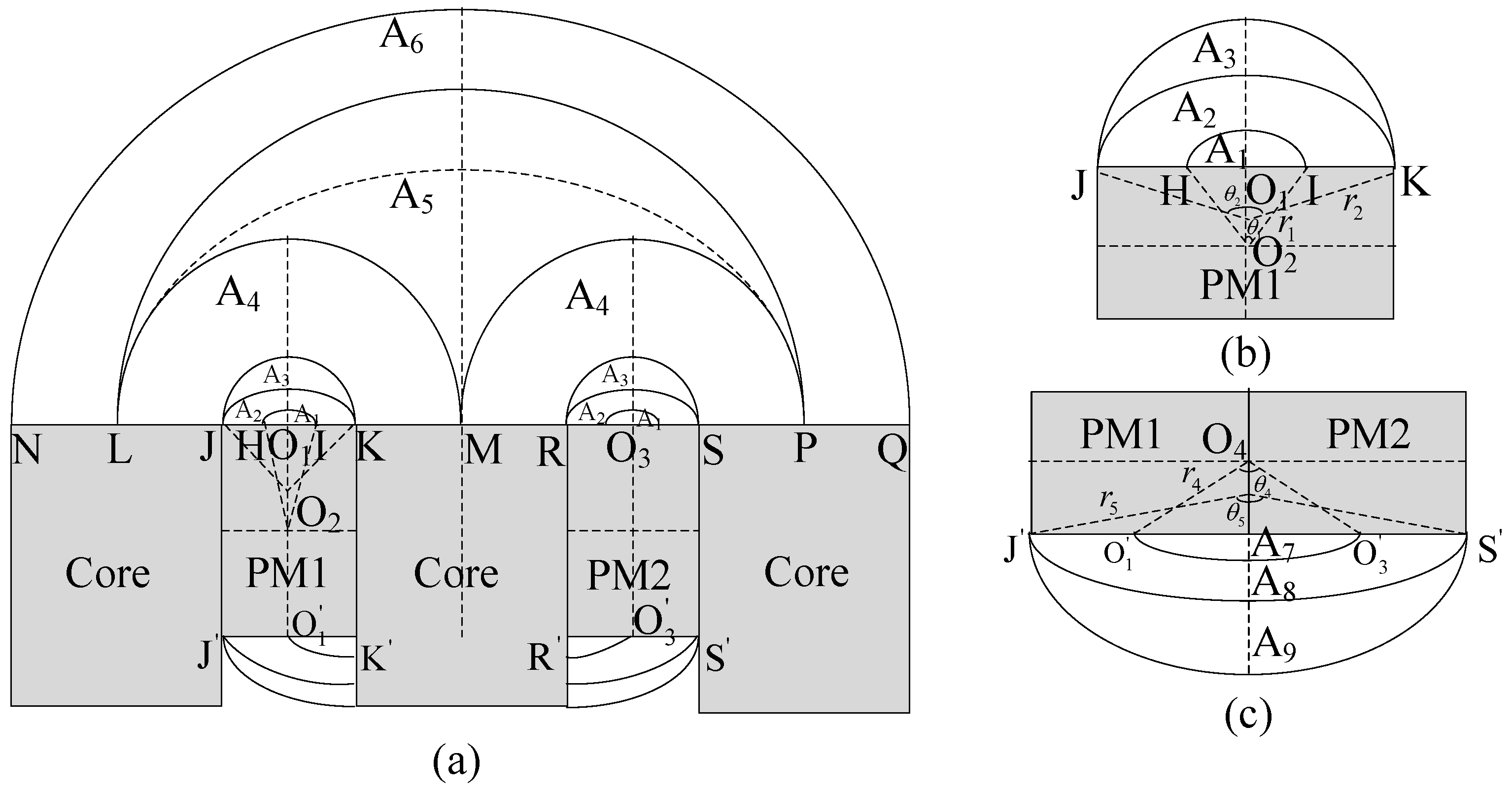
3. Biasing Ability Analysis of the PM Considering the Leakage Effect
3.1. Arch-Type Flux Tube A1
3.2. Similar Circular-Type Flux Tube A2
3.3. Semi-Lunar Type Flux Tube A3
3.4. Semi-Circular Type Flux Tube A4
3.5. Semi-Lunar Type Flux Tube A5
3.6. Semi-Circular Type Flux Tube A6
4. Results
4.1. FEA Simulation and Optimization
- SCFCLs without PMs: Wloss1 = GWh
- Hybrid SCFCLs without small section: Wloss2 = GWh
- HSCFCL with small section: Wloss3 = GWh
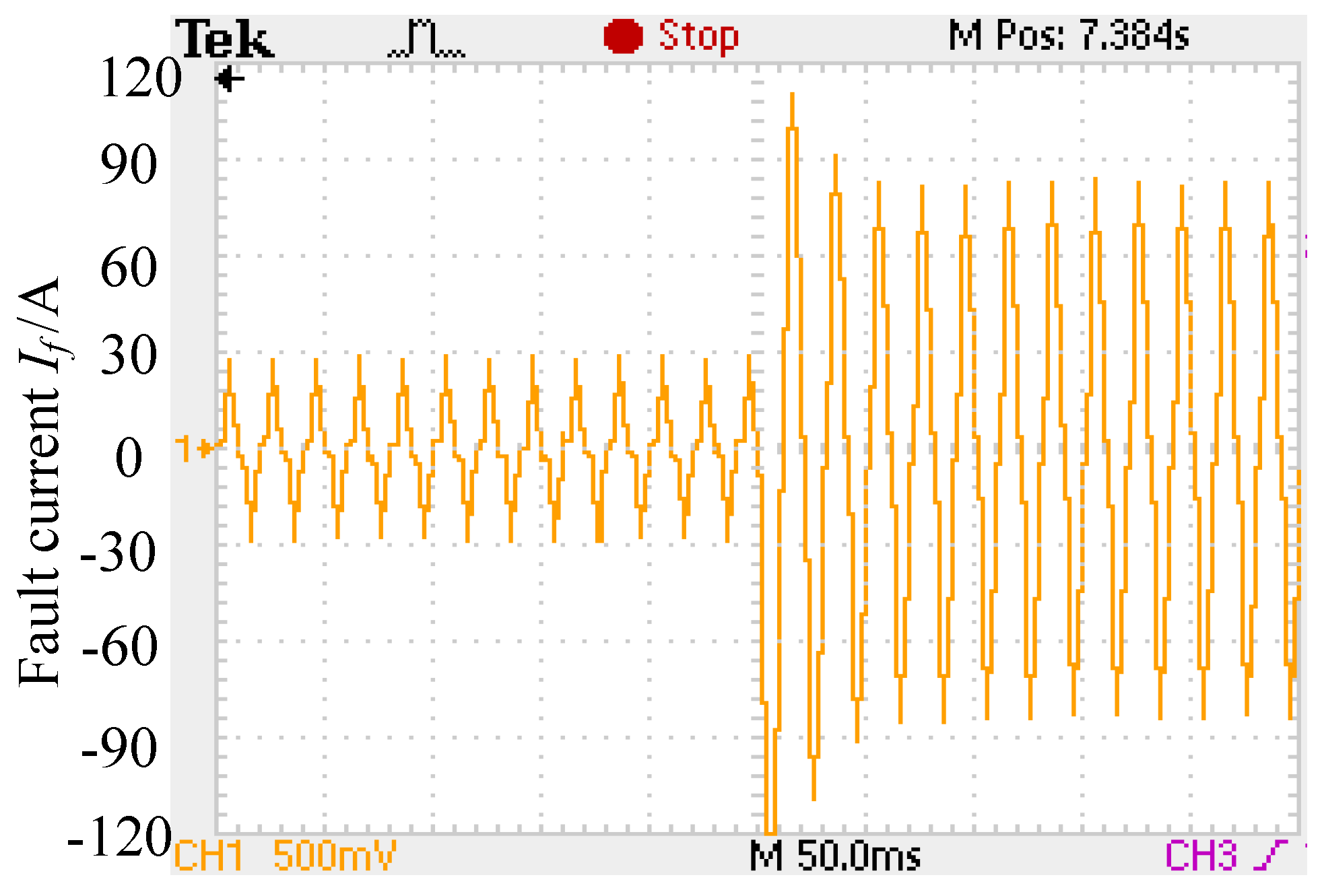
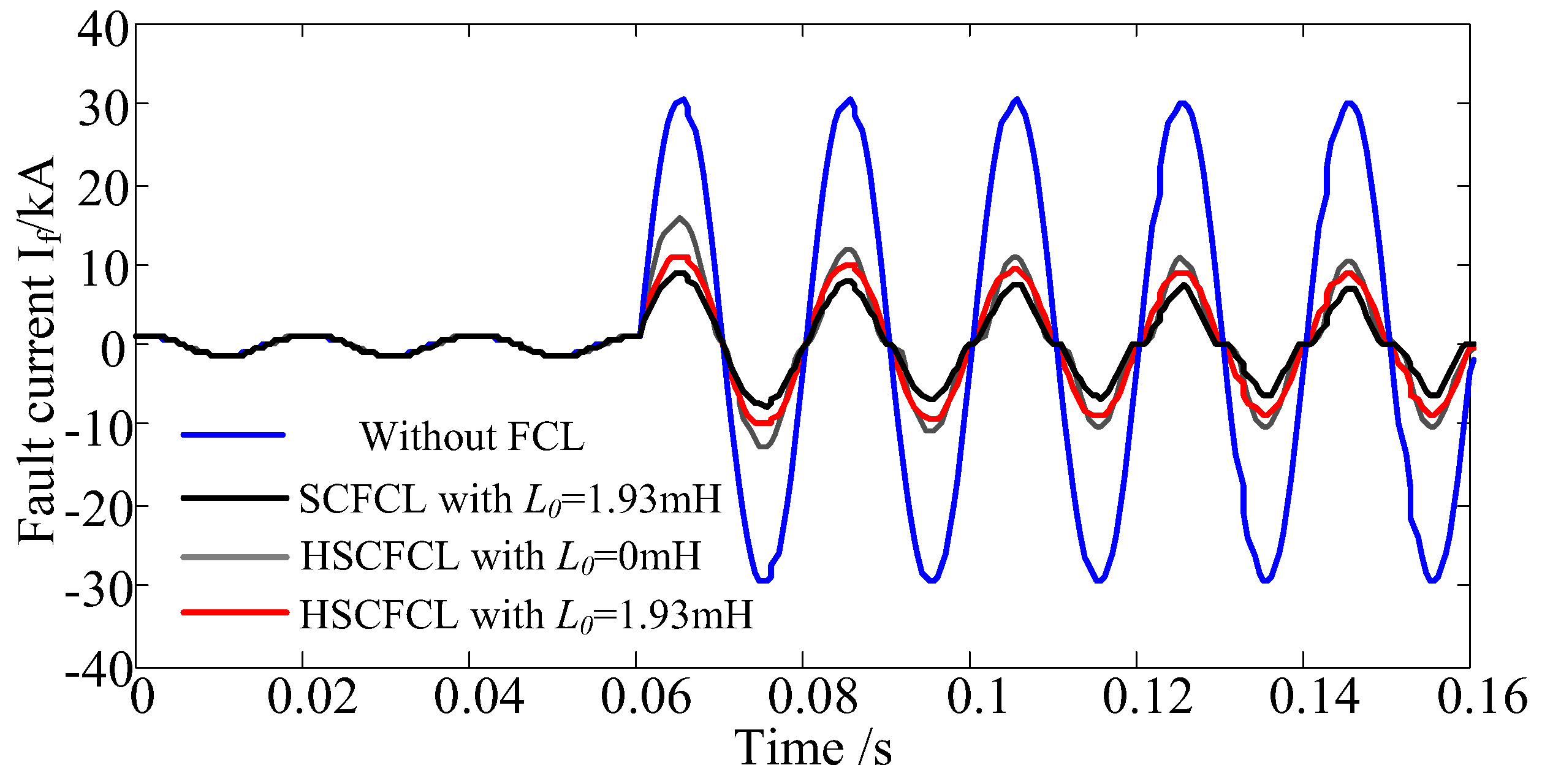
4.2. Experimental Study
5. Conclusions
Acknowledgments
Author Contributions
Conflicts of Interest
References
- Kies, A.; Schyska, B.U.; von Bremen, L. Curtailment in a highly renewable power system and its effect on capacity factors. Energies 2016, 9, 510. [Google Scholar] [CrossRef]
- Sun, X.; Zhang, B.; Tang, X.; McLellan, B.C.; Höök, M. Sustainable Energy Transitions in China: Renewable Options and Impacts on the Electricity System. Energies 2016, 9, 980. [Google Scholar] [CrossRef]
- Lu, J.; Wang, W.; Zhang, Y.; Cheng, S. Multi-Objective Optimization of Hybrid Renewable Energy System Using an Enhanced Multi-Objective Evolutionary Algorithm. Energies 2017, 10, 674. [Google Scholar] [CrossRef]
- Abramovitz, A.; Smedley, K.M.; De La Rosa, F.; Moriconi, F. Prototyping and Testing of a 15 kV/1.2 kA Saturable Core HTS Fault Current Limiter. IEEE Trans. Power Deliv. 2013, 28, 1271. [Google Scholar] [CrossRef]
- Radmanesh, H.; Fathi, S.H.; Gharehpetian, G.B.; Heidary, A. Bridge-Type Solid-State Fault Current Limiter Based on AC/DC Reactor. IEEE Trans. Power Deliv. 2016, 31, 200. [Google Scholar] [CrossRef]
- Hong, H.; Su, B.; Niu, G.J.; Tian, B.; Li, Q.; Wang, L.Z.; Xin, Y.; Su, B.; Zhang, Z.H.; Zhang, K. Design, Fabrication, and Operation of the Cryogenic System for a 220 kV/300 MVA Saturated Iron-Core Superconducting Fault Current Limiter. IEEE Trans. Appl. Supercond. 2014, 24, 1. [Google Scholar] [CrossRef]
- Chen, L.; Chen, H.; Yang, J.; Yu, Y.; Zhen, K.; Liu, Y.; Ren, L. Coordinated Control of Superconducting Fault Current Limiter and Superconducting Magnetic Energy Storage for Transient Performance Enhancement of Grid-Connected Photovoltaic Generation System. Energies 2017, 10, 56. [Google Scholar] [CrossRef]
- Xue, S.; Gao, F.; Sun, W.; Li, B. Protection Principle for a DC distribution system with a resistive superconductive fault current limiter. Energies 2015, 8, 4839–4852. [Google Scholar] [CrossRef]
- Gunawardana, S.M.; Commins, P.A.; Moscrop, J.W.; Perera, W. Transient Modeling of Saturated Core Fault Current Limiters. IEEE Trans. Power Deliv. 2016, 31, 2008–2017. [Google Scholar] [CrossRef]
- Commins, P.A.; Moscrop, J.W. Analytical Nonlinear Reluctance Model of a Single-Phase Saturated Core Fault Current Limiter. IEEE Trans. Power Deliv. 2013, 28, 450. [Google Scholar] [CrossRef]
- Jia, Y.; Ainslie, M.D.; Hu, D.; Yuan, J. Numerical Simulation and Analysis of a Saturated-Core-Type Superconducting Fault Current Limiter. IEEE Trans. Appl. Supercond. 2017, 27, 1–5. [Google Scholar] [CrossRef]
- Prigmore, J.R.; Mendoza, J.A.; Karady, G.G. Comparison of Four Different Types of Ferromagnetic Materials for Fault Current Limiter Applications. IEEE Trans. Power Deliv. 2013, 28. [Google Scholar] [CrossRef]
- Jia, Y.; Shi, Z.; Zhu, H.; Geng, Y.; Zou, J.; Yuan, J. Cognition on the Current-Limiting Effect of Saturated-Core Superconducting Fault Current Limiter. IEEE Trans. Magn. 2015, 51, 1–4. [Google Scholar] [CrossRef]
- Oliveira, F.; Amorim, A.; Encarnação, L.; Fardin, J.; Orlando, M.; Silva, S.; Simonetti, D. Enhancing LVRT of DFIG by using a superconducting current limiter on rotor circuit. Energies 2016, 9, 16. [Google Scholar] [CrossRef]
- Chen, L.; Tu, X.; Chen, H.; Yang, J.; Wu, Y.; Shu, X.; Ren, L. Technical Evaluation of Superconducting Fault Current Limiters Used in a Micro-Grid by Considering the Fault Characteristics of Distributed Generation, Energy Storage and Power Loads. Energies 2016, 9, 769. [Google Scholar] [CrossRef]
- Mukhopadhyay, S.C.; Dawson, F.P.; Iwahara, M.; Yamada, S. A novel compact magnetic current limiter for three phase applications. IEEE Trans. Magn. 2000, 36, 3568. [Google Scholar] [CrossRef]
- Knott, J.C.; Moscrop, J.W. Increasing Energy Efficiency of Saturated-Core Fault Current Limiters with Permanent Magnets. IEEE Trans. Magn. 2013, 49, 4132. [Google Scholar] [CrossRef]
- Yuan, J.; Lei, Y.; Wei, L.; Tian, C.; Chen, B.; Du, Z. A novel bridge-type hybrid saturated core fault current limiter based on permanent magnets. IEEE Trans. Magn. 2015, 51, 1–4. [Google Scholar] [CrossRef]
- Li, Q.; Xu, J.; Zou, L.; Lou, J. Modelling methodology and experimental verification of the permanent-magnet-biased saturation-based fault current limiter. IET Electr. Power Appl. 2012, 6, 504. [Google Scholar] [CrossRef]
- Wei, L.; Chen, B.; Yuan, J.; Tian, C.; Zhong, Y.; Li, X.; Gao, Y.; Muramatsu, K. Performance and Optimization Study of a Novel Compact Permanent-magnet-biased Fault Current Limiter. IEEE Trans. Magn. 2017, 53, 1–4. [Google Scholar] [CrossRef]
- Moscrop, J.W. Experimental Analysis of the Magnetic Flux Characteristics of Saturated Core Fault Current Limiters. IEEE Trans. Magn. 2012, 49, 874. [Google Scholar] [CrossRef]
- Chen, B.; Wei, L.; Tian, C.; Lei, Y.; Yuan, J. Parameter Design and Performance Investigation of A Novel Bridge-Type Saturated Core Fault Current Limiter. IEEE Trans. Power Deliv. 2017, 32, 1049. [Google Scholar] [CrossRef]


| Symbol | Definition | Symbol | Definition |
|---|---|---|---|
| φm1 | Flux of cores I | Xnom | Normal impedance of HSCFCL |
| φm2 | Flux in cores II | ZFCL | Inserted impedance of HSCFCL |
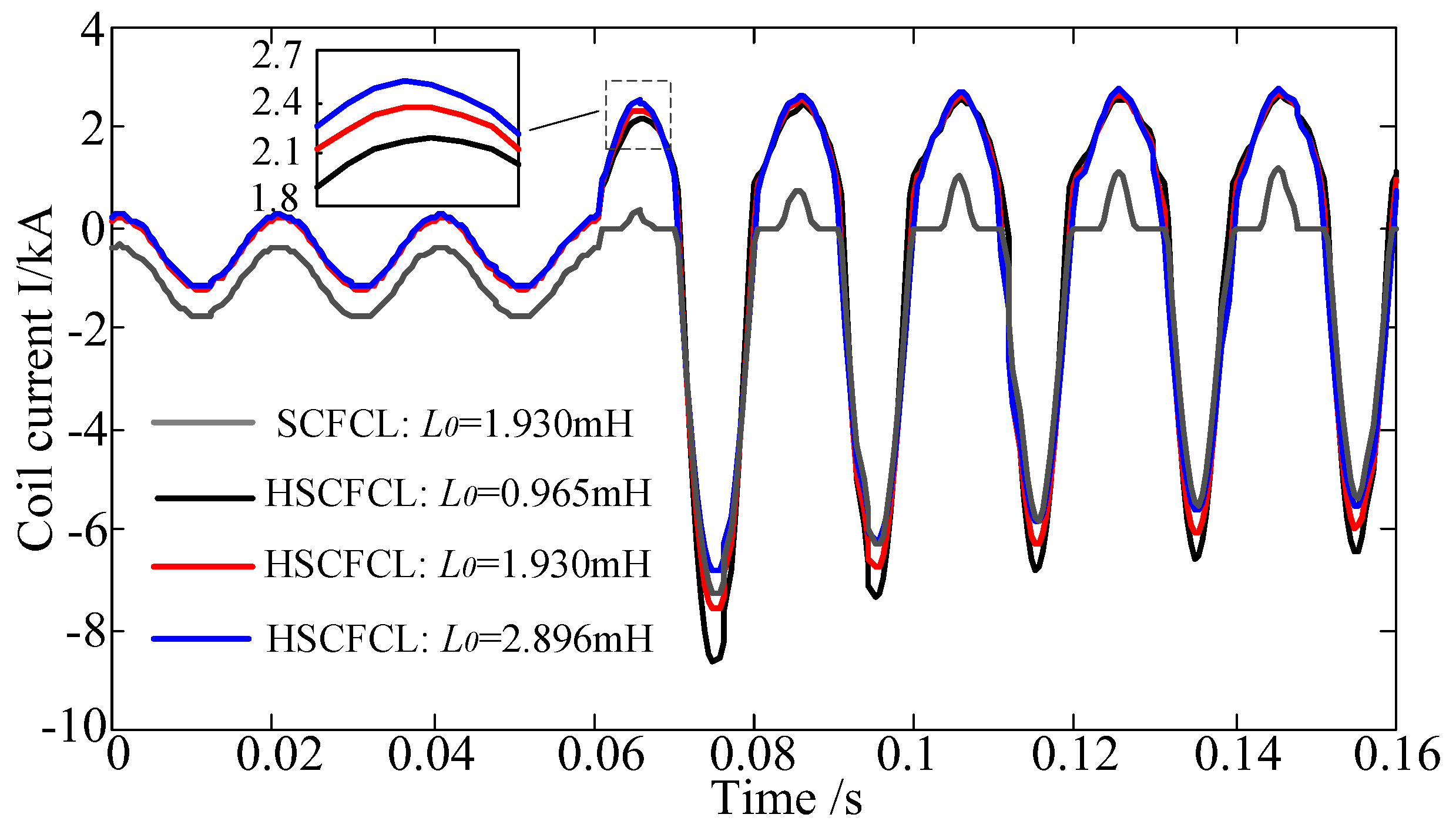
| φm3 | Flux in cores III | L0 | Limiting inductance |
| re1 | Reluctance of core I | MMFd | DC MMF produced by DC coils |
| re2 | Reluctance of core II | MMFPM | DC MMF produced by PMs |
| ru | Reluctance of core III | ∆MMFPM | Improvement of DC MMF |
| μu | Unsaturated permeability of iron core | Id | DC current |
| μsr | Saturated permeability of iron core | Se | Cross-sectional area of core I |
| Lu | Unsaturated inductance of a winding | le | Length of core I |
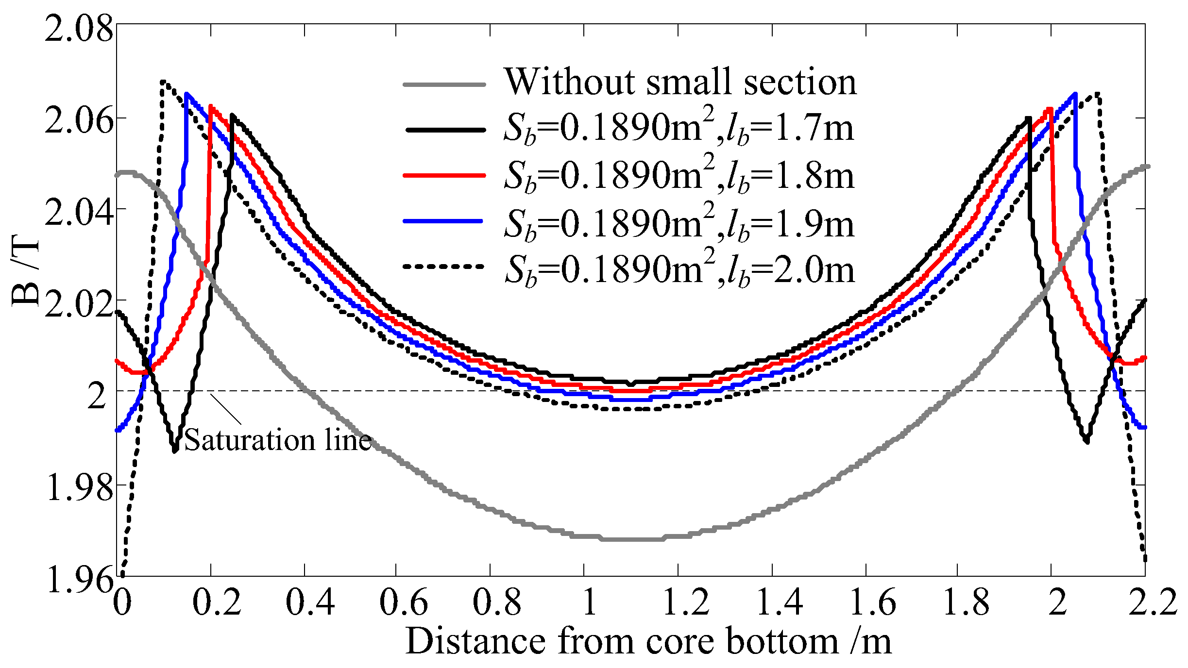
| Ls | Saturated inductance of a winding | Sb | Cross-sectional area of small section |
| N | Number of winding turns | lb | Length of small section |
| Parameter | Value |
|---|---|
| Cross-sectional area of cores I and II/m2 | 0.2025 |
| Cross-sectional area of cores III/m2 | 0.261 |
| Cross-sectional area of small section/m2 | 0.189 |
| Length of cores le/m | 2.2 |
| Length of small section lb/m | 1.8 |
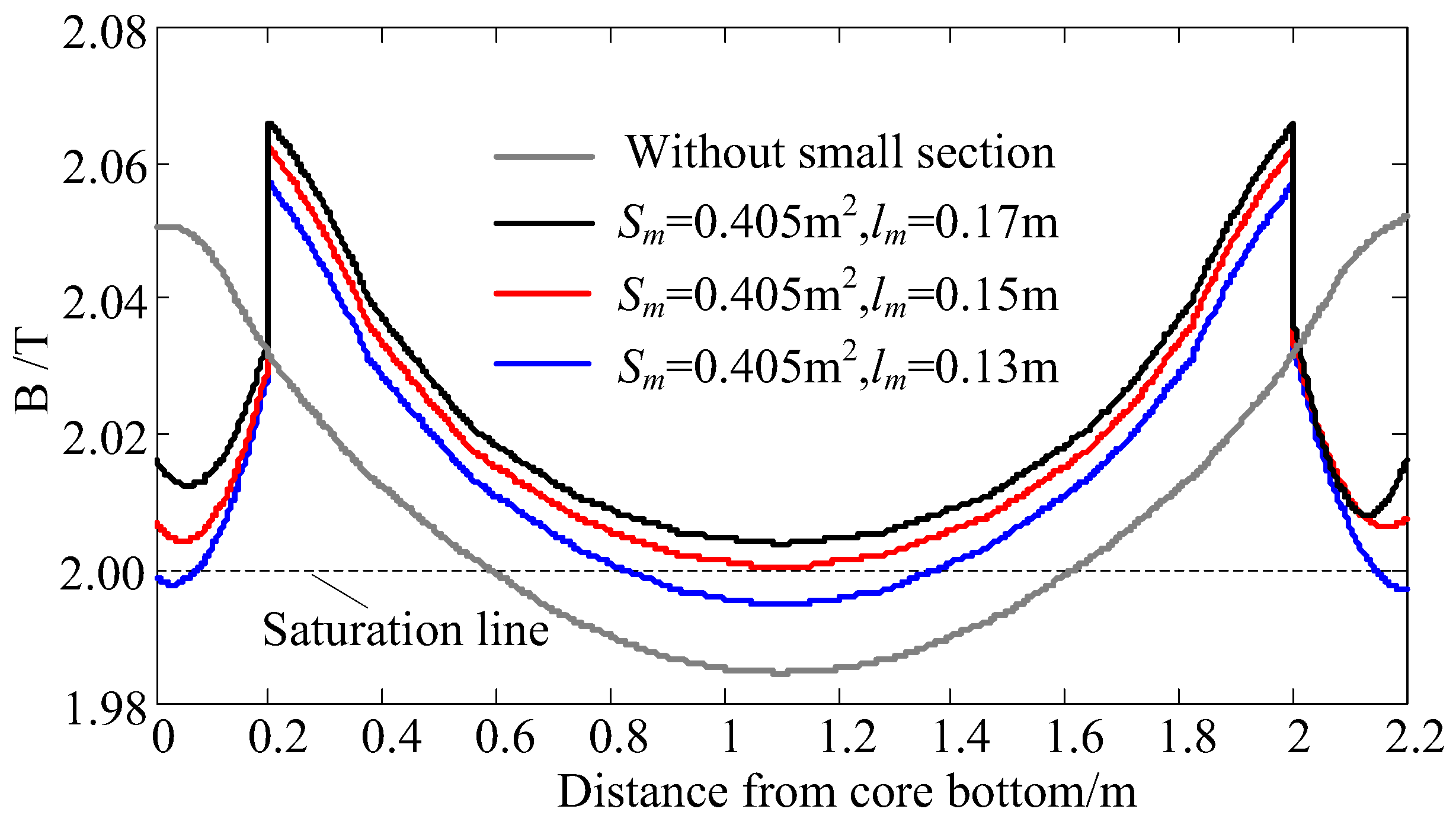
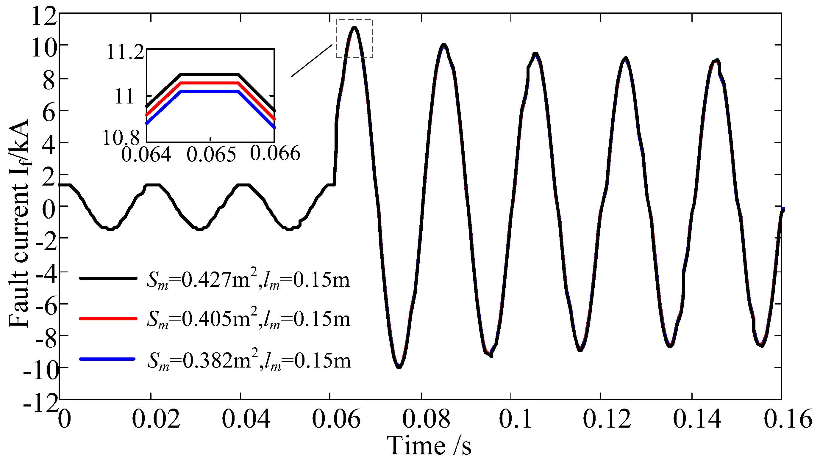
| Cross-sectional area of PM/m2 | 0.405 |
| Length of PM/m | 0.15 |
| Number of winding turns N | 37 |
| Inductance of limiting inductor L0/mH | 1.93 |
| Steel cores | Hs = 10 kA/m, Bs = 2.0 T |
| Permanent magnets | Hc = 836 kA/m, Br = 1.45 T |
| Parameter | Value |
|---|---|
| Cross-sectional area of cores I and II/m2 | 0.0025 |
| Cross-sectional area of cores III/m2 | 0.00325 |
| Cross-sectional area of small section/m2 | 0.00244 |
| Length of cores le/m | 0.27 |
| Length of small section lb/m | 0.19 |
| Cross-sectional area of PM/m2 | 0.005 |
| Length of PM/m | 0.01 |
| DC-biasing current/A | 10 |
| Inductance of limiting inductor L0/mH | 8 |
| Steel cores | Hs = 10 kA/m, Bs = 2.0 T |
| Permanent magnets | Hc = 836 kA/m, Br = 1.45 T |
© 2018 by the authors. Licensee MDPI, Basel, Switzerland. This article is an open access article distributed under the terms and conditions of the Creative Commons Attribution (CC BY) license (http://creativecommons.org/licenses/by/4.0/).
Share and Cite
Wei, L.; Chen, B.; Liu, Y.; Tian, C.; Yuan, J.; Bu, Y.; Zhu, T. Performance Investigation and Optimization of a Novel Hybrid Saturated-Core Fault-Current Limiter Considering the Leakage Effect. Energies 2018, 11, 61. https://doi.org/10.3390/en11010061
Wei L, Chen B, Liu Y, Tian C, Yuan J, Bu Y, Zhu T. Performance Investigation and Optimization of a Novel Hybrid Saturated-Core Fault-Current Limiter Considering the Leakage Effect. Energies. 2018; 11(1):61. https://doi.org/10.3390/en11010061
Chicago/Turabian StyleWei, Liangliang, Baichao Chen, Yushun Liu, Cuihua Tian, Jiaxin Yuan, Yuxin Bu, and Tianan Zhu. 2018. "Performance Investigation and Optimization of a Novel Hybrid Saturated-Core Fault-Current Limiter Considering the Leakage Effect" Energies 11, no. 1: 61. https://doi.org/10.3390/en11010061