Article

Design Method for the Coil-System and the Soft Switching Technology for High-Frequency and High-Efficiency Wireless Power Transfer Systems

1
School of Electrical and Power Engineering, China University of Mining and Technology, Xuzhou 221008, China
2
Electrical Energy Management Research Group, University of Bristol, Bristol BS8 1TH, UK
*
Author to whom correspondence should be addressed.
Energies 2018, 11(1), 7; https://doi.org/10.3390/en11010007
Submission received: 20 October 2017 / Revised: 7 December 2017 / Accepted: 18 December 2017 / Published: 21 December 2017

Abstract

:
Increasing the resonant frequency of a wireless power transfer (WPT) system effectively improves the power transfer efficiency between the transmit and the receive coils but significantly limits the power transfer capacity with the same coils. Therefore, this paper proposes a coil design method for a series-series (SS) compensated WPT system which can power up the same load with the same DC input voltage & current but with increased resonant frequency. For WPT systems with higher resonant frequencies, a new method of realizing soft-switching by tuning driving frequency is proposed which does not need to change any hardware in the WPT system and can effectively reduce switching losses generated in the inverter. Eighty-five kHz, 200 kHz and 500 kHz WPT systems are built up to validate the proposed methods. Experimental results show that all these three WPT systems can deliver around 3.3 kW power to the same load (15 Ω) with 200 V input voltage and 20 A input current as expected and achieve more than 85% coil-system efficiency and 79% system overall efficiency. With the soft-switching technique, inverter efficiency can be improved from 81.91% to 98.60% in the 500 kHz WPT system.

1. Introduction

Wireless power transfer (WPT) systems, which can transfer energy from a power source to isolated loads across air gap without any direct electrical contacts, are attracting more and more attention. They have been widely used to power up electrical equipment or recharge its batteries. Due to the elimination of physical contacts between the source and the load, WPT systems can greatly enhance the flexibility and safety of the electrical equipment.
A two-coil WPT system is composed of a transmit coil and a receive coil that are separated by an air gap. There is mutual inductance and leakage inductance between the two coils [1]. Electrical energy is wirelessly transferred through the mutual inductance between the two coils; the leakage inductance, nevertheless, does not have a direct contribution to the active power transfer. However, the large gap between the transmit and receive coils results in a low coupling coefficient, typically in the range of 5–30%, depending on the distance, alignment, and size of the coils [2]. This feature leads to large leakage inductance but small mutual inductance which would significantly limit the power transfer efficiency between the two coils. A popular method of cancelling out the effect of the leakage inductance is to make use of compensation capacitances to tune the two coils so that they work at the resonant frequency. The compensation capacitances are from either discrete capacitors or parasitic capacitances of the coils. There are four basic topologies of the compensation circuit, according to how the compensation capacitances are added to the transmit and receive coils: series-series (SS), series-parallel (SP), parallel-series (PS), and parallel-parallel (PP) topologies [3]. In this paper, the basic SS compensation topology is adopted for its simple structure, but the analysis and the method can also be applied to the other compensation topologies.
Though there have been many papers studying the WPT characteristics [4,5], various compensation topologies [6,7] and coil structures, few papers give a detailed account of their coil design. The coil design can be very challenging, as multiple design parameters and requirements must be considered simultaneously to build up a WPT system, including input/output parameter requirements, inverter efficiency, coil-to-coil efficiency, voltage-ampere (VA) rating, device stress and stability. Increasing the resonant frequency of the WPT system effectively improves the power transfer efficiency but significantly limits the power transfer capacity with the same coils. Therefore, in this paper, a design method for a loosely coupled SS resonant WPT system of given resonant frequency, input and load conditions is proposed which can help to increase the system resonant frequency without impacting the system power level.
As the single-phase H-bridge DC-AC inverter is widely used to generate the high frequency power to excite the transmit coil in WPT systems [6,7,8,9,10,11], a reliable high-frequency DC-AC inverter is critical to output high-frequency power. To increase the resonant/driving frequency and reduce inverter losses, wide bandgap semiconductor devices such as SiC MOSFETs [9] and soft switching techniques are adopted in high-power WPT systems. Different compensation topologies are studied in-depth to achieve soft switching. In [6], the author proposes a double-sided LCC compensation network and its tuning method to realize zero voltage switching (ZVS) for the primary-side switches in the WPT system. A zero-current switching (ZCS) condition could also be achieved by tuning the parameters of the LCC compensation network [7], but those topologies need additional passive components in the circuit which will increase losses and component count. Others seek to realize soft switching through inverter control strategies. In [10], a polyphase current-fed push–pull resonant converter with full-autonomous operation based on mutual magnetic coupling among the phases for polyphase WPT applications has been presented: full ZVS of all three converters has been achieved with accurate 120° phase balancing at 73.5 kHz. A DC-voltage-controlled variable capacitor for stabilizing the ZVS frequency of a resonant converter for WPT system is proposed in [11]. It can be seen that those inverter-side control methods and those specially designed structures are too complex. Besides this, soft-switching is desired under different operating conditions in a WPT system; however, the system parameters in [6,7,10,11] are fixed once designed and set, and adjusting the values of those additional components to realize full load-condition soft switching is impractical for variable load-resistance systems such as a battery charging system. Therefore, in this paper, a phase shift strategy is proposed to realize soft switching by simply changing the input impedance of the inverter through tuning the driving frequency. Detailed analysis and accurate calculation methods are both presented. Compared to the existing soft-switching methods, the components in our WPT system do not need to be tuned corresponding to the system operating conditions, and are hence more suitable for practical applications where the WPT system is used for charging batteries or powering up different electrical equipment. Besides, soft-switching on and soft-switching off can be chosen arbitrarily according to the requirements.
To validate the proposed coil-system design method and soft-switching method, 85 kHz, 200 kHz and 500 kHz WPT systems are all built up. Designed with the proposed coil-system design method, all these three WPT systems can deliver around 3.3 kW power to the same load (15 Ω) with the same input voltage (200 V) and the expected 20 A DC input current. With the soft-switching strategy presented in this paper, the inverter efficiency can be effectively improved, particularly in WPT system with higher resonant frequencies. For example, the inverter efficiency can be improved from 89.81% to 98% in the 500 kHz system. Even though the frequency tuning method would lead to a slight decrease in the coil-to-coil efficiency, the overall efficiency can still be maintained at the similar level compared to that of the resonant conditions. With the greatly improved inverter efficiency, the volume of the heatsink can be effectively reduced, the power density increased, providing a more reliable operating environment for the inverter.
The main contributions of this paper are (1) the proposal of a method for designing the coils in the WPT system which can help to increase the system resonant frequency without affecting the system power level; (2) the proposal of a phase shift strategy to create soft switching conditions under various operating conditions by simply changing the input impedance of the inverter through tuning the driving frequency. This soft-switching realization method does not need to change any hardware in the WPT system and has a better applicability. The proposed soft-switching method greatly enhances the inverter efficiency, which can help reduce the volume of the heatsink and the total system and provide a more reliable operating environment for the inverter, particularly in high resonant frequency WPT systems.

2. Theoretical Analysis of the WPT System

In this section, the mathematical model of an SS compensated two-coil WPT system is built up first which not only studies the power transfer characteristics but also facilitates the design of a new WPT system with specific requirements. The impacts of resonant frequency on the power transfer performance is analyzed and a new coil-system design method is proposed subsequently.

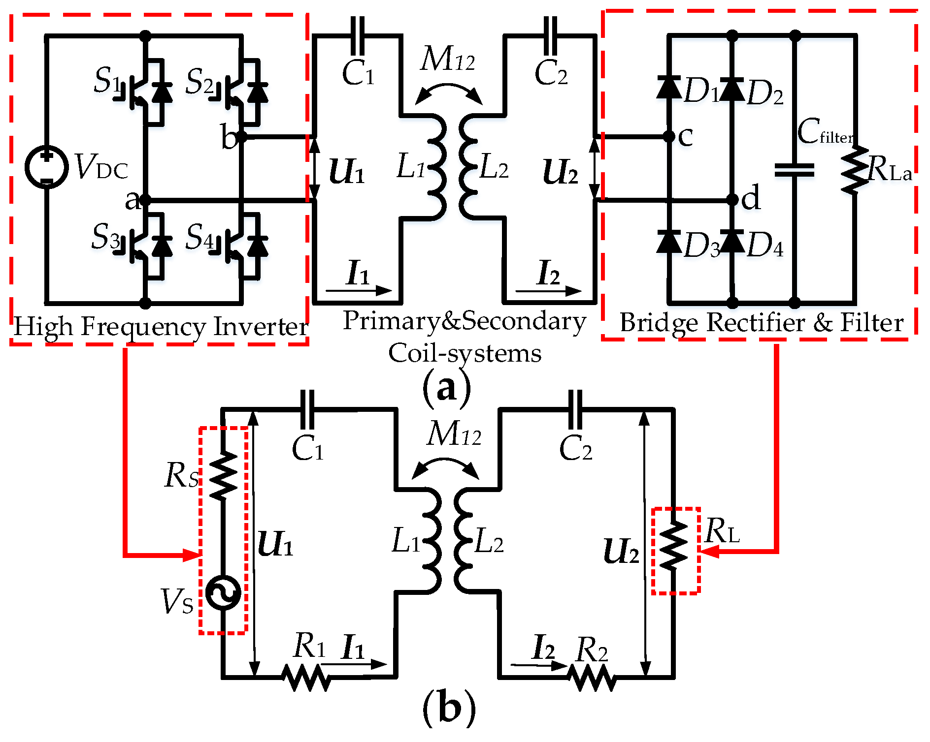
2.1. Circuit Model of Two-Coil WPT-System

The mathematical model of a WPT system is derived first to study its power transfer characteristics. The circuit schematic diagram of the WPT system with SS compensation topology in this work is shown in Figure 1a. The coil system is assumed to be symmetrical. The system can be simplified into the equivalent model as shown in Figure 1b, where VS is an equivalent voltage source with an internal resistance RS; U1 is the output voltage phasor of the high-frequency inverter applied to the primary-side coil system; U2 is the output voltage phasor of the secondary-side coil system and the input voltage to the H-bridge rectifier. The H-bridge rectifier, filter capacitor and the actual load R L a are modelled as an equivalent resistance RL. In this simplified model, R1 and R2 are the parasitic resistance in the primary and secondary sides, respectively, consisting of the parasitic resistance of the coils and the compensation capacitors. I1 and I2 are the current phasors of the primary side and the secondary side respectively. In the later analysis, the bold symbols stand for the phasor of these voltages and currents, otherwise stand for the RMS values of the fundamental of these voltages and currents.
When the WPT system operates at resonant frequency, U2 and I2 are in phase, as such, the power transfer equals to U2 multiply by I2. Assuming 100% power efficiency of the rectifier, according to the law of energy conservation, the relationship between the actual and the equivalent loads can be expressed as Equation (1).
R L 0.81 R L a
The resonant angular frequency ( ω r ) of a resonant WPT system equals the driving angular frequency ( ω d ), and can be expressed as,
ω d = ω r = 1 / L 1 C 1 = 1 / L 2 C 2
where C1 and C2 are the compensation capacitances; L1 and L2 are the self-inductance of the coils.
With the lumped-element circuit shown in Figure 1b, the WPT system can be expressed in matrix form as follows:
[ U 1 0 ] = [ Z 1 j ω d M 12 j ω d M 12 Z 2 ] [ I 1 I 2 ]
where Z 1 = R 1 + j ω d L 1 j / ( ω d C 1 ) is the impedance of the primary side; Z 2 = R L + R 2 + j ω d L 2 j / ( ω d C 2 ) is the impedance of the secondary side.
Therefore, I1 and I2 can be derived from Equations (3) as Equations (4) and (5) respectively.
I 1 = Z 2 U 1 ω d 2 M 12 2 + Z 1 Z 2
I 2 = j ω d M 12 U 1 ω d 2 M 12 2 + Z 1 Z 2
With Equations (4) and (5), the power injected into the primary-side coil system, Ppri, the power delivered to the load by the secondary-side coil system, Psec, and accordingly, the coil-to-coil efficiency, η c c then can be expressed as Equations (6)–(8). From Equations (6)–(8), it can be found that the input power, output power and the coil-to-coil efficiency are all closely related to the resonant frequency, the load resistance and the mutual inductance between the two coils. In addition, the output power can be easily adjusted by tuning the DC input voltage without affecting the coil-to-coil efficiency.
P p r i = U 1 I 1 = U 1 I 1 = U 1 2 ( R L + R 2 ) ω r 2 M 12 2 + R 1 ( R L + R 2 )
P s e c = I 2 2 R L = I 2 2 R L = ω r 2 M 12 2 U 1 2 R L ( ω r 2 M 12 2 + R 1 ( R L + R 2 ) ) 2
η c c = P s e c P p r i = ω r 2 M 12 2 R L ( ω r 2 M 12 2 + R 1 ( R L + R 2 ) ) ( R L + R 2 )

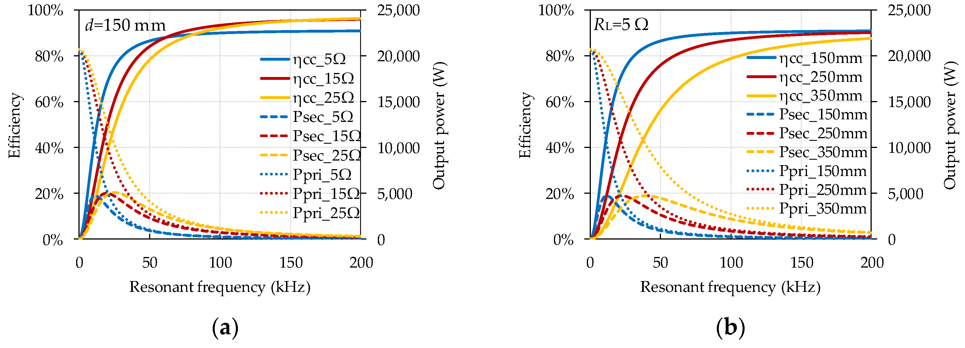
2.2. Effect of the Resonant Frequency

From Equations (4)–(8), it can be seen that ω d has an impact on all the system operating indexes (I1, I2, Ppri, Psec); therefore, to build up a new WPT system, the first consideration is the resonant frequency. SAE J2954 recommends 85 kHz for wireless charging EV batteries [12]; ORNL’s (Oak Ridge National Laboratory) experimental setup adopts 22 kHz [5], and in [13], the resonant frequency is 1 MHz, both with kilowatt-level output power. Higher resonant frequency settings can be found in [14,15]. It can be seen that there is no final conclusion about the resonant frequency design in the WPT system. Therefore, it is meaningful to investigate the impacts of the resonant frequency in a WPT system with given coils.
In this study, the resonant frequency varies between 1 Hz and 200 kHz by adjusting the compensation capacitance. It should be noted that even if the coil structure is not changed, the quality factor (Q = ωL/R) of the coil will change with the frequency. In this calculation, the DC input voltage is held constant at 100 V; the self-inductance of the two coils are both 66.58 μH; the coil-to-coil vertical distance is set to be 150 mm, 250 mm and 350 mm, emulating different coupling conditions; the load resistance is set to be 5 Ω, 15 Ω and 25 Ω to provide different load conditions. With Equations (7) and (8), the output power Psec and the coil-to-coil efficiency ηCC are plotted against the resonant frequency as shown in Figure 2.
From Figure 2, it is obvious that no matter what the load resistance and coupling coefficient are, the higher the resonant frequency is, and the higher the coil-to-coil efficiency will be. As for the output power, there is always an optimal resonant frequency that results in the maximum output power, and after the peak output power point, the higher the resonant frequency is, the smaller the output power will be. Therefore, with given coils, increasing the resonant frequency can effectively improve the coil-to-coil efficiency, but both the input and output power can be seriously limited (Equation (8)). Besides, Equations (6)–(8) indicate that when DC input voltage, load resistance and resonant frequency are fixed, the mutual inductance (M12) of the coil system should be carefully designed to satisfy the requirements on system efficiency and power transfer capacity at the same time.

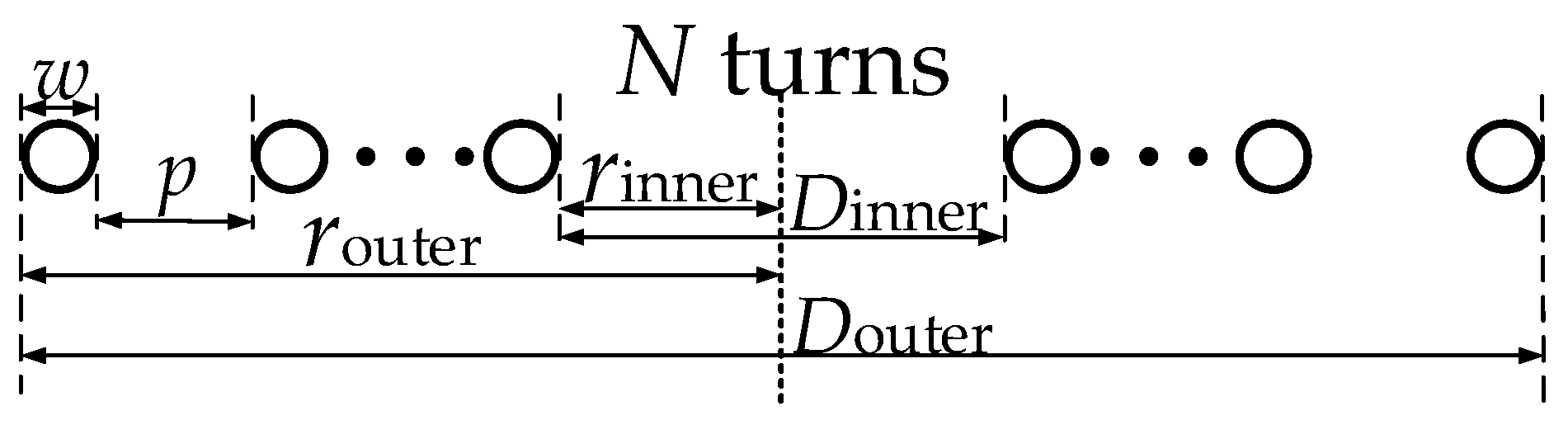
2.3. Coil-System Design Method

Once the input voltage, input current, load resistance and resonant frequency are determined, the required mutual inductance of the coil system can be derived from Equation (4) as
M 12 = 1 ω r ( U 1 Z 1 I 1 ) Z 2 I 1 .
This shows that the higher the designed resonant frequency is, the smaller the required mutual inductance is. There are three approaches to deceasing the mutual inductance: (1) increasing the coil-to-coil distance with the same coils, which can reduce the coupling coefficient and thereby can increase the power transfer distance; (2) reducing the coil size, which can reduce both the self-inductance and the mutual inductance, and the size and volume of the coil system; (3) the coupling coefficient and the self-inductance of the coils can also be adjusted at the same time as long as Equation (9) is satisfied to ensure the expected mutual inductance without changing the coil-to-coil distance.
To simplify the experiments and provide more coil scenarios to validate the feasibility of the proposed coil system design method, tuning the self-inductance of the coil is adopted in this work and the coupling coefficient is assumed to be constant, which can be achieved by adjusting the coil-to-coil distance. Therefore, different coils need to be designed for WPT systems with different resonant frequencies under the previous assumptions. However, if the structure of the coils is changed, the parasitic resistance of the coils will also change. Compared to the load resistance (several tens of ohms), the parasitic resistance of the coils is usually very small (several tens of milliohms) and can be neglected [6,16]; besides this, as Litz wire is used and the channel width of the flat spiral coils in this work is large enough, proximity effect is also neglected, and therefore Equation (9) can be simplified as
M 12 1 ω r U 1 R L I 1 .
Accordingly, with the specified coupling coefficient, the required coil self-inductance can be derived from the required mutual inductance in Equation (10) as
L 1 = L 2 = M 12 / k .
The elevation view of a flat spiral coil is shown in Figure 3, where N is the turns of the flat spiral coil, rinner and router are the inner radius and outer radius of the coil respectively, w is the diameter of the wires used for winding the coils, and p is the channel width between two adjacent wires.
The self-inductance of the flat spiral coil can be derived from a modified Wheeler’s formula [17] for a single-layer helical coil as Equation (12). The expression of inductance is validated for a wide variety of coils [18] except when the coil has very few turns [19]. With Equations (11) and (12), the detailed design parameters of flat spiral coils can be derived, meanwhile, FEA (finite element analysis) software (Maxwell V14, ANSYS, Inc., Canonsburg, PA, USA) can be used to validate the specific designed coils and can satisfy the requirements in Equation (9).
L = N 2 ( D o u t e r N ( w + p ) ) 2 16 D o u t e r + 28 N ( w + p ) × 39.37 10 6   ( H )
In the experiments, the maximum outer radius of the coil is 290 mm, as the coil size is limited by the electric equipment; the minimum inner radius for fabricating flat spiral coils is 30 mm. The overall wire radius is 3 mm for carrying the current required by the power transfer and made by Litz wires for decreasing the AC resistance of the coils. Channel width is set to be 10 mm to reduce proximity effect. The inner radius and coil turns can be adjusted to satisfy Equation (12).

3. Analysis of Inverter Operation and Soft-Switching WPT System

With the coil-system design method presented in Section 2, the resonant frequency can be effectively improved without sacrificing the system power level. From Equation (2), it can be seen that the driving frequency of the WPT system should be increased with the system resonant frequency accordingly. Higher driving frequency increases the losses in the inverter, which not only significantly limits the system overall efficiency but also degrades the system safety and increases the size and weight of the heatsink used in the inverter. In order to study and design suitable soft-switching techniques to reduce the switching losses, the hard-switching operation of the MOSFETs in the inverter at resonant frequency will be analyzed below first.

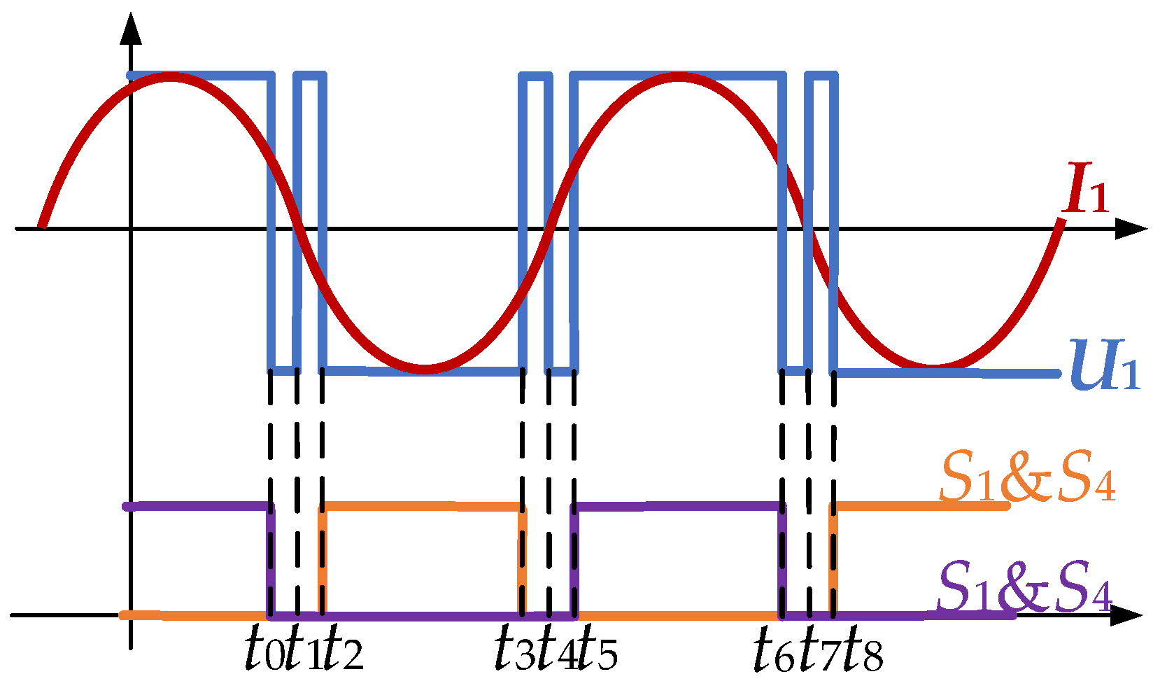
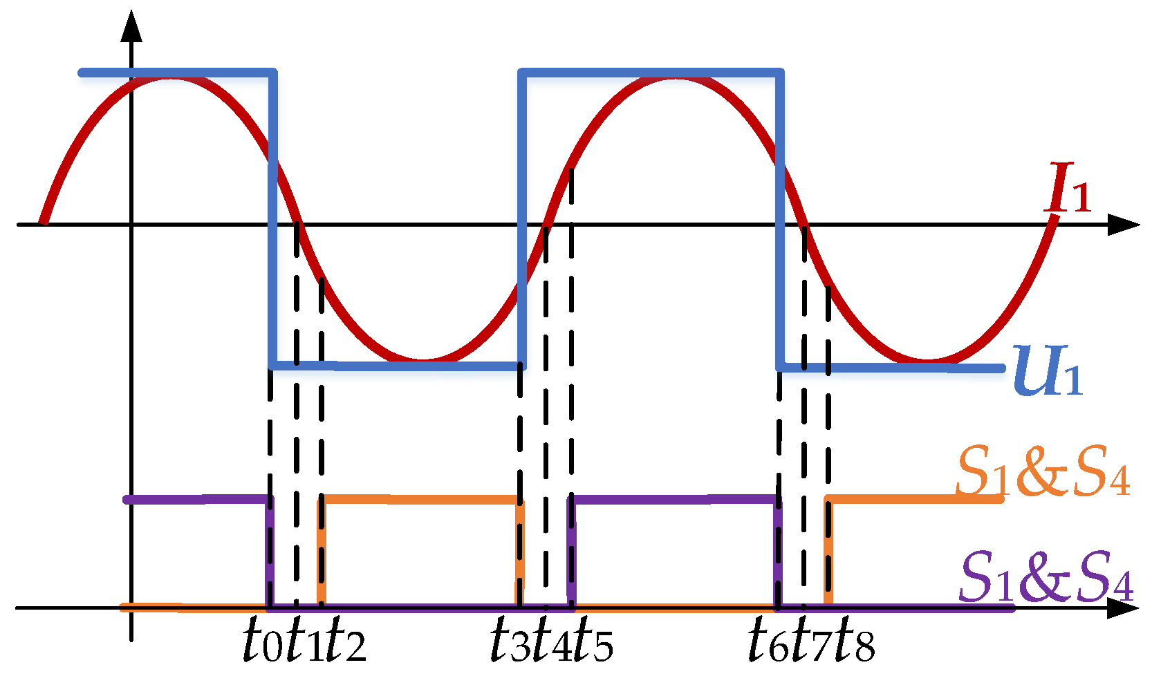
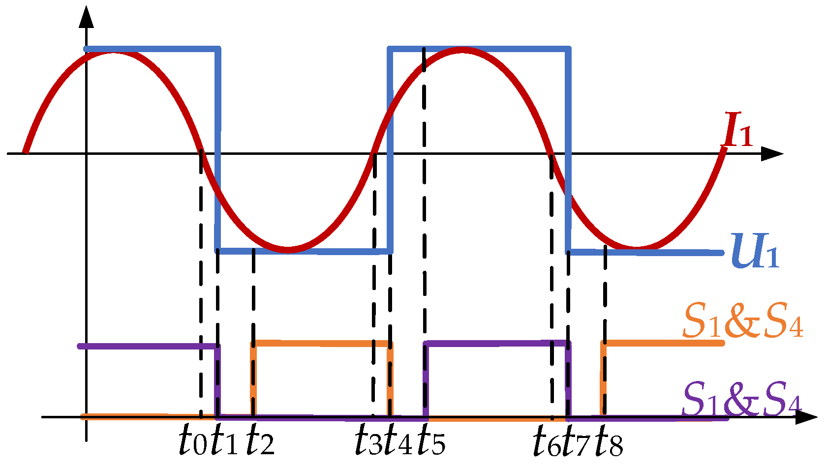
3.1. Analysis of Inverter Operation Modes

The waveforms of U1 & I1 of the inverter are shown in Figure 4, and explained stage by stage below.
Before t0: S1 & S4 are on and S2 & S3 are off. U1 and I1 are both positive but I1 has started to decrease, as L1 is discharging in the LC resonant circuit.
t0t1: S1 & S4 are turned off, the body diodes of S2 & S3, d2 & d3, are on and the system operates in dead-time. U1 is negative but I1 is still positive because the discharging inductor L1 is charging the capacitor C1 and I1 keeps decreasing. S1 & S4 are hard switching off.
t1t2: Four MOSFETs are all off, the system still operates in dead-time. At t1, inductor L1 finishes its discharging process and capacitor C1 starts to discharge at the same time because this is a resonant LC circuit. Therefore, I1 is negative after crossing zero and U1 is positive, and d1 & d4 are on.
t2t5: S1 & S4 remain off and S2 & S3 are turned on at t2. U1 and I1 are both negative but I1 will decrease when the capacitor C1 is fully discharged and repeat the process from t0t2 with opposite direction of output voltage and current. S2 & S3 are hard switching on.
It is obvious that whichever device turns on or off, it is in hard switching. As analyzed previously, increasing the system resonant frequency can improve the system coil-to-coil efficiency, increase the power transfer distance, or reduce the coil size. However, with an increase in the system resonant frequency, the needed driving frequency should be accordingly increased, which in turn will increase the switching losses of the MOSFETs in the inverter and the possibility of a device failure. The soft-switching technique can be adopted to increase the resonant frequency and decrease the switching losses. From the previous analysis, it can be found that the switching transient always happen in the dead-time and the hard switching of the switching device is caused by the LC circuit operating in resonant condition and appearing pure resistive. This can also be found if the phase between U1 and I1 can be shifted to remove the period of t0t1 or t1t2, which not only eliminates the pulses during the dead-time, but also realizes soft-switching. Tuning the input impedance of the inverter to be inductive or capacitive can easily tune the phase between U1 and I1.

3.2. Strategy for Soft-Switching Implementation

To shift the phase between the output voltage and current of the inverter, the input impedance of the inverter should be tuned to capacitive or inductive. There are three methods to change the input impedance of the inverter: (1) tuning the compensation capacitance on both sides; (2) tuning single-side compensation capacitance; and (3) tuning the driving frequency. However, when the load resistance or coil-to-coil distance change, the expected compensation capacitance also needs to be adjusted, as a result, it is difficult to realize the first two methods in practical systems which operate in a wide load range. The third one can be easily realized by tuning the driving frequency, which entails no hardware change in the WPT system. Therefore, tuning driving frequency is adopted in this work.
The moments when the input impedance of the inverter is inductive and the zero-current point of I1 is shifted out of the dead-time and the output voltage and current waveforms of the SiC-based converter in a full cycle are shown in Figure 5. The operation modes in the first half cycle (t0t3) are explained and the converter works in the second half cycle in a manner symmetrical to the first half cycle:
Before t0: S1 & S4 are turned on and S2 & S3 are turned off. U1 and I1 are both positive but I1 has started to decrease as L1 is discharging in the LC resonant circuit.
t0t2: At t0, switches S1 to S4 are all turned off. d2 & d3 are turned on. Because of the inductive impedance of the inverter, the current lags the voltage. Therefore, when U1 cross zero, I1 will be still positive but decreasing because the discharging inductor L1 is charging capacitor C1 and I1 will cross zero during the dead-time at t1 and then be negative. At t2: S2 & S3 are switching on. The current is diverting from their respective body diodes to their channels, therefore, MOSFETs S2 & S3 are soft switching on.
t2t3: S1 & S4 are off and S2 & S3 are turned on. U1 and I1 are both negative and I1 will increase first and then decrease because of the LC circuit. I1 will lag U1 in crossing zero because of the inductive impedance. Therefore, at t3, S2 & S3 are hard switching off.
When the input impedance of the inverter is capacitive, the zero-current point of I1 is shifted out of the dead-time and the output voltage and current waveforms of the converter in a full cycle are shown in Figure 6; operation modes in the first half cycle are explained from t0t2 and the converter works in the second half cycle in a manner symmetrical to the first half cycle:
Before t0: S1 & S4 are on and S2 & S3 are off. U1 and I1 are both positive but I1 has started to decrease because of the LC resonant circuit and the discharging of L1.
t0t1: At t0, I1 crosses zero and become negative because the capacitive impedance of the inverter causes the current leading the voltage. During this period, S1 & S4 are still on and conduct current, but the direction of I1 is reversed.
t1t2: At t1, S2 & S3 remain off, and S1 & S4 are switched off. U1 and I1 both keep their directions, therefore the current diverts from the channel of S1 & S4 into their body diodes d1 & d4, creating soft-switching condition for S1 & S4 off.
At t2, S2 & S3 are switching on. I1 flows through S2 & S3, d1 & d4 are off, and U1 will be zero immediately. Therefore, at t2, S2 & S3 are hard-switching on.
Previous analyses indicate that, when the zero-cross point of I1 is shifted out of the dead-time, only one pair of the body diodes is conducting during the dead-time, and the MOSFETs can achieve soft-switching on or off according to the impedance of the inverter. The inductive input impedance of the inverter creates soft-switching conditions for MOSFET turning on and capacitive input impedance of the inverter create soft-switching conditions for MOSFET turning off.
As the input impedance of the inverter is tuned by tuning the driving frequency, and then the WPT system no longer operates in resonant condition, its impacts on the system operation performance should be analyzed and the system operating under these two different soft-switching conditions needs to be compared with that under resonant condition in terms of coil-to-coil efficiency, inverter efficiency, system overall efficiency and output power.

3.3. Implementation of the Soft-Switching Techniques by Tuning the Driving Frequency

It has been analyzed that, in order to realize soft-switching operating conditions, the driving frequency should be slightly away from the resonant frequency to change the input-impedance characteristic of the inverter. However, for coil-to-coil distances less than the critical coupling distance, twin output power peaks will occur on either side of the resonant frequency even if the primary and secondary circuits are perfectly tuned to the same frequency. This is the frequency splitting phenomenon and is explained in [20].
When the frequency splitting phenomenon occurs, the maximum output power can be found at another two frequencies which are on each side of the resonant frequency, with slightly less than the maximum coil-to-coil efficiency at the resonant frequency. This also shows that, when the frequency splitting phenomenon disappears, with an increase in the driving frequency, the peak output power is found at the resonant frequency, and the output power decreases rapidly when the driving frequency is away from the resonant frequency. Therefore, when driving frequency is tuned to realize soft-switching, the tuning range should be as small as possible to reduce the impact on the output power and the coil-to-coil efficiency.
Now, with a specific WPT system and specially-made coils, the next step is finding a suitable frequency offset to achieve soft switching. It has been analysed that the zero-cross point of I1 should be shifted out of the dead-time by adjusting the input impedance of the inverter. Therefore, the phase difference of U1 & I1, ϕ , should satisfy
ϕ > 2 π ( t 2 ) T
α = cos ϕ < cos ( 2 π ( t 2 ) T )
where t is the dead-time and T is the period of the inverter output voltage. It means that the delay time between U1 and I1 is larger than a half of the dead-time.
The phase difference ϕ is also the phase angle (Equation (15)) of the input impedance of the inverter Zin (Equation (16)). Equations (17) and (18) stand for the real part and the imaginary part of the input impedance (Equation (16)).
cos ϕ = R | Z i n | = α
Z i n = U 1 I 1 = Z 1 + ω d 2 M 12 2 Z 2 = R + j X
R = R 1 + ω d 2 M 12 2 ( R 2 + R L ) ( R 2 + R L ) 2 + ( ω d L 2 1 / ( ω d C 2 ) ) 2
X = ω d L 1 1 ( ω d C 1 ) ω d 2 M 12 2 ( ω d L 2 1 / ( ω d C 2 ) ) ( R 2 + R L ) 2 + ( ω d L 2 1 / ( ω d C 2 ) ) 2
To simplify the calculation, R1 and R2 are assumed to be zero, then Equations (16) and (17) can be transformed into Equations (19) and (20).
R = ω d 2 M 12 2 R L R L 2 + ( ω d L 2 1 / ( ω d C 2 ) ) 2
X = ω d L 1 1 ( ω d C 1 ) ω d 2 M 12 2 ( ω d L 2 1 / ( ω d C 2 ) ) R L 2 + ( ω d L 2 1 / ( ω d C 2 ) ) 2
It has been analyzed that, when the system is expected to operate at soft-switching condition by tuning the driving frequency, the impacts on the system output power and efficiency should be kept as small as possible; therefore, the driving frequency should be as close as possible to the resonant frequency when creating soft-switching conditions. To simplify the calculation, Equation (21) is assumed.
ω d L 2 1 / ( ω d C 2 ) 0
Then, Equations (19) and (20) can be simplified into Equations (22) and (23).
R = ω d 2 M 12 2 R L
X = ω d L 1 1 ( ω d C 1 )
From previous analysis, the final driving frequency is related to M12, L1, C1, RL, t and T, and is given as in Equation (24), where x in can be derived as Equation (25). Equation (24) means that the tuned driving frequency can exactly shift the zero-cross point of I1 out of the dead-time to reduce the impacts on the system output power and efficiency. In other words, with the driving frequency derived from Equation (24), the zero-cross point of I1 will be exactly moved from t1 to t0 or t2 in Figure 4e.
( 1 α 1 ) M 12 2 R L 2 x 3 L 1 2 x 2 2 L 1 C 1 x + 1 C 1 2 = 0
x = ω d 2
Obviously, the driving frequency is a real and positive value, and it has been known that there will be two driving frequencies around the resonant frequency that can shift zero-current point out of the dead-time. Meaningful results (positive real numbers) can therefore be derived from Equations (24) and (25). As the assumption in the calculation may lead to errors in the calculated results, to make sure the zero-current point can be shifted out of the dead-time, the calculated driving frequency will be substituted into the full Equations (15)–(18) to validate Equation (14) in MATLAB. If Equation (14) is not valid, the calculated driving frequency will be fine-tuned up or down, i.e., when soft-switching on is expected, the driving frequency will be tuned up; when soft-switching on is expected, the driving frequency will be tuned down.

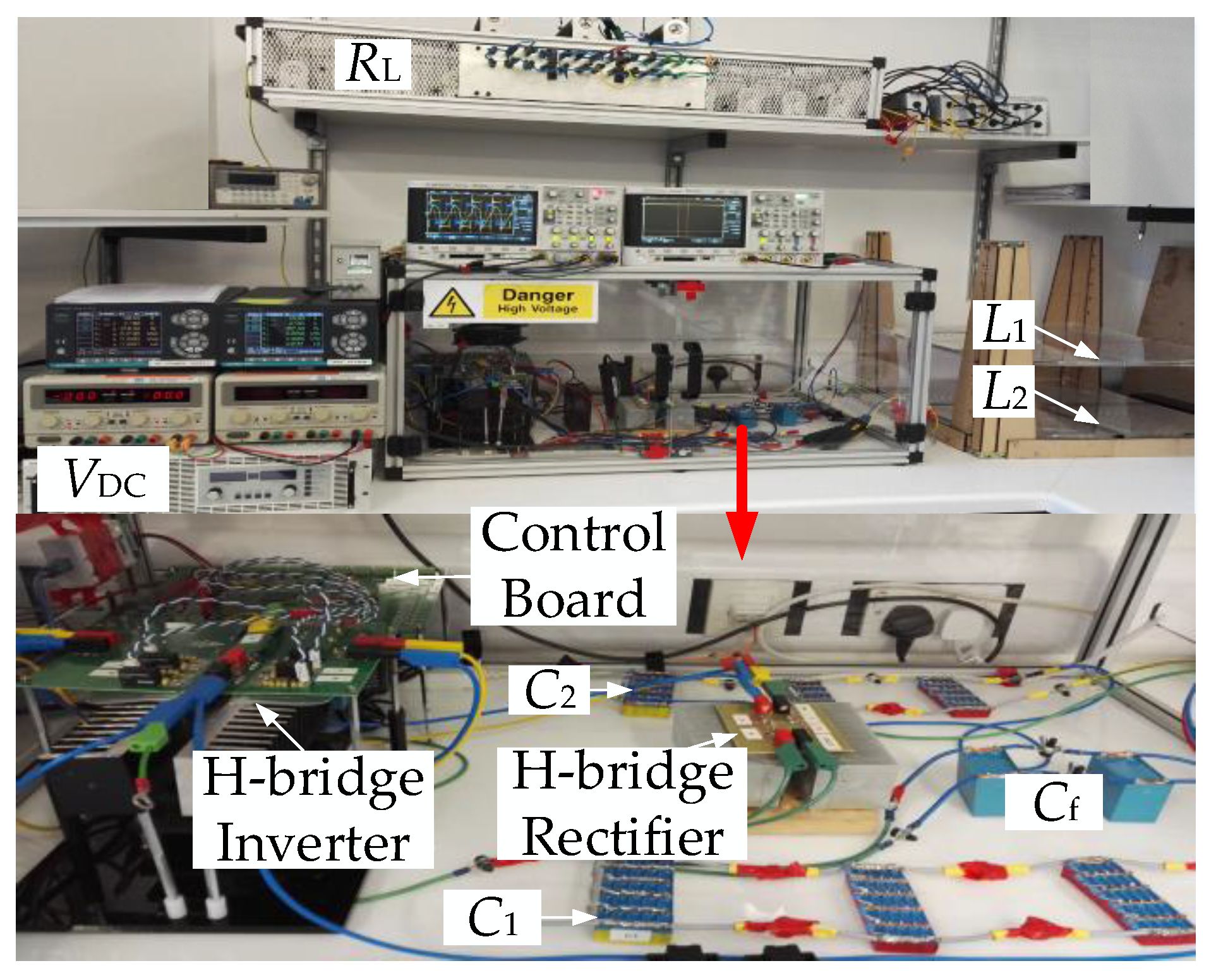
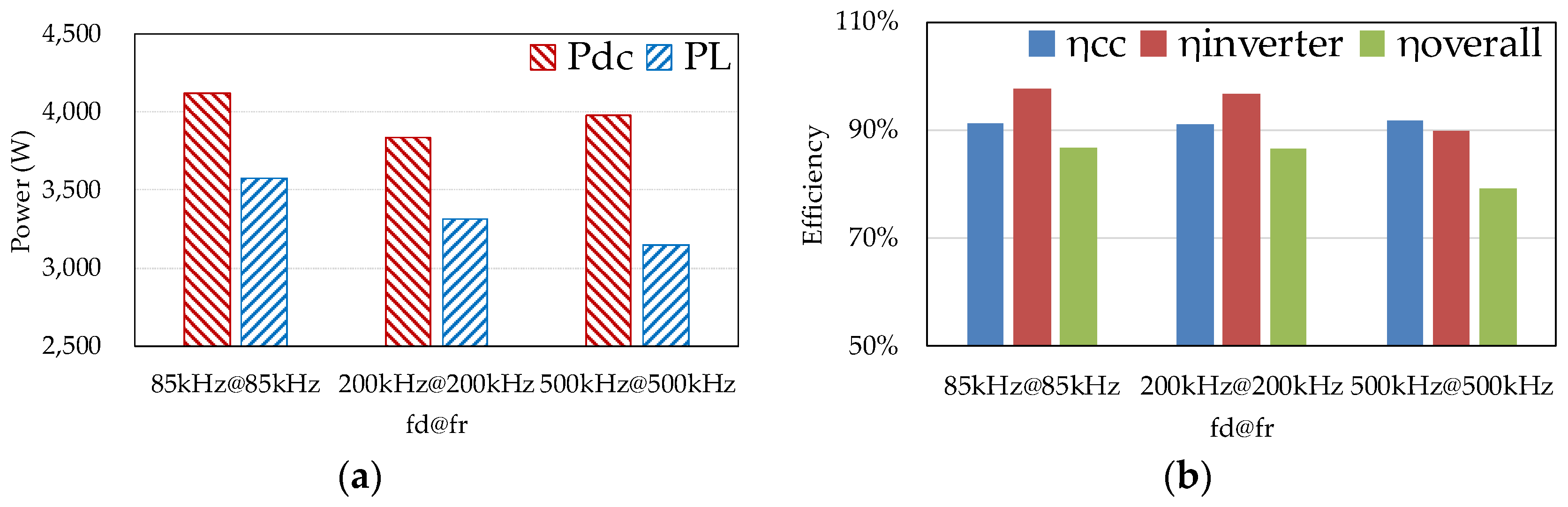
4. Experimental Verification and Discussions

4.1. Design of the 85 kHz, 200 kHz and 500 kHz WPT Coil Systems

To validate the methods presented in this paper, 85 kHz, 200 kHz and 500 kHz coil-systems are all built up with different coil design as shown in Table 1. The expected coupling coefficient is set to be 0.3 in the WPT systems. The actual measured values of the parameters of the experimental systems are also listed in Table 1. The experimental setup is shown in Figure 7.
Each WPT system has the same power supply and load; the difference between them is the coil system designed by the method presented in Section 2. SiC power MOSFETs S1-S4 (CREE, Durham, NC, USA, C2M0040120D) and SiC diodes (CREE, Durham, NC, USA, C4D20120) are used in the DC-AC inverter and AC-DC rectifier of the WPT system. Power supply EA-PS 81000-30 DC is used to supply power to the whole system. Two NOORMA 4000 Power analysers are used to measure the DC power supply, inverter output power, rectifier input power and the load power. 400 MHz passive probes (PMK, Heusenstamm, Germany PHV 1000) are used to measure the gate-to-source voltage and drain-to-source voltage. Rogowski coils are used to measure the drain current. Differential probe (Agilent, Santa Clara, CA, USA, N2791A) is used to measure the output voltage of the inverter. 50 MHz current probe (Agilent, Santa Clara, CA, USA, 1147A) is used to measure the output current of the inverter. 100 MHz oscilloscope (Agilent, Santa Clara, CA, USA, MSO-X 3014A) is used to capture the voltage and current waveforms.
In this work, RL is assumed to be 10 Ω for calculation. According to Equation (1), the actual load resistance RLa is 12.35 Ω. Considering the errors and assumptions in the calculations, when the parasitic resistance is considered in the design and the calculation, the actual load resistance should be slightly larger than the calculated value and the final load resistance used in the experiments is set to be 15 Ω, which is also of a similar order to that used in various other works dealing with WPT systems for battery charging [21,22]. In this work, the DC voltage is 200 V, and the DC current is 20 A. As such, the expected DC input power will be 4 kW. The self-inductance of the coil is measured by an impedance analyzer (WAYNE KERR, West Sussex, UK, 6500B). The mutual inductance is adjusted through changing the coil-to-coil distance to satisfy Equation (9). According to the design method presented in Section 2.3, detailed design parameters for 85 kHz, 200 kHz and 500 kHz WPT systems are listed in Table 1.
Besides this, one obvious advantage of increasing the resonant frequency shown in Table 1 is that the required mutual inductance is smaller, which reduces the coil size and weight. In other words, with the same coupling coefficient of the coil system, the higher the resonant frequency is, and the smaller and lighter the coil will be.
With the experimental platform of the WPT system, these three coil systems are tested with their respective designed resonant frequency to verify the proposed coil design method. Figure 8 shows the measured efficiency and input/output power of these three WPT systems operating at their respective resonant frequencies with the same input voltage, load resistance and coupling coefficient. The horizontal axis fd@fr denotes the driving frequency and the resonant frequency, e.g., 85 kHz@90 kHz means the driving frequency is 85 kHz and the resonant frequency is 90 kHz.
This demonstrates that, with the design method, all these three systems can achieve the expected input power of around 4 kW with around 3.3 kW output power, and the coil-system efficiency and the overall efficiency can be kept at around 90% and 80% respectively. The higher the resonant frequency is, the lower the inverter efficiency will be, i.e., the inverter efficiency decreases from 98% to 90% with the resonant frequency increasing from 85 kHz to 500 kHz. And the low inverter efficiency seriously limits the overall efficiency even though the coil-system efficiency can be kept the same level and will also limit higher resonant frequency WPT systems. Therefore, soft switching is needed for improving the inverter efficiency to build WPT systems with higher resonant frequency.

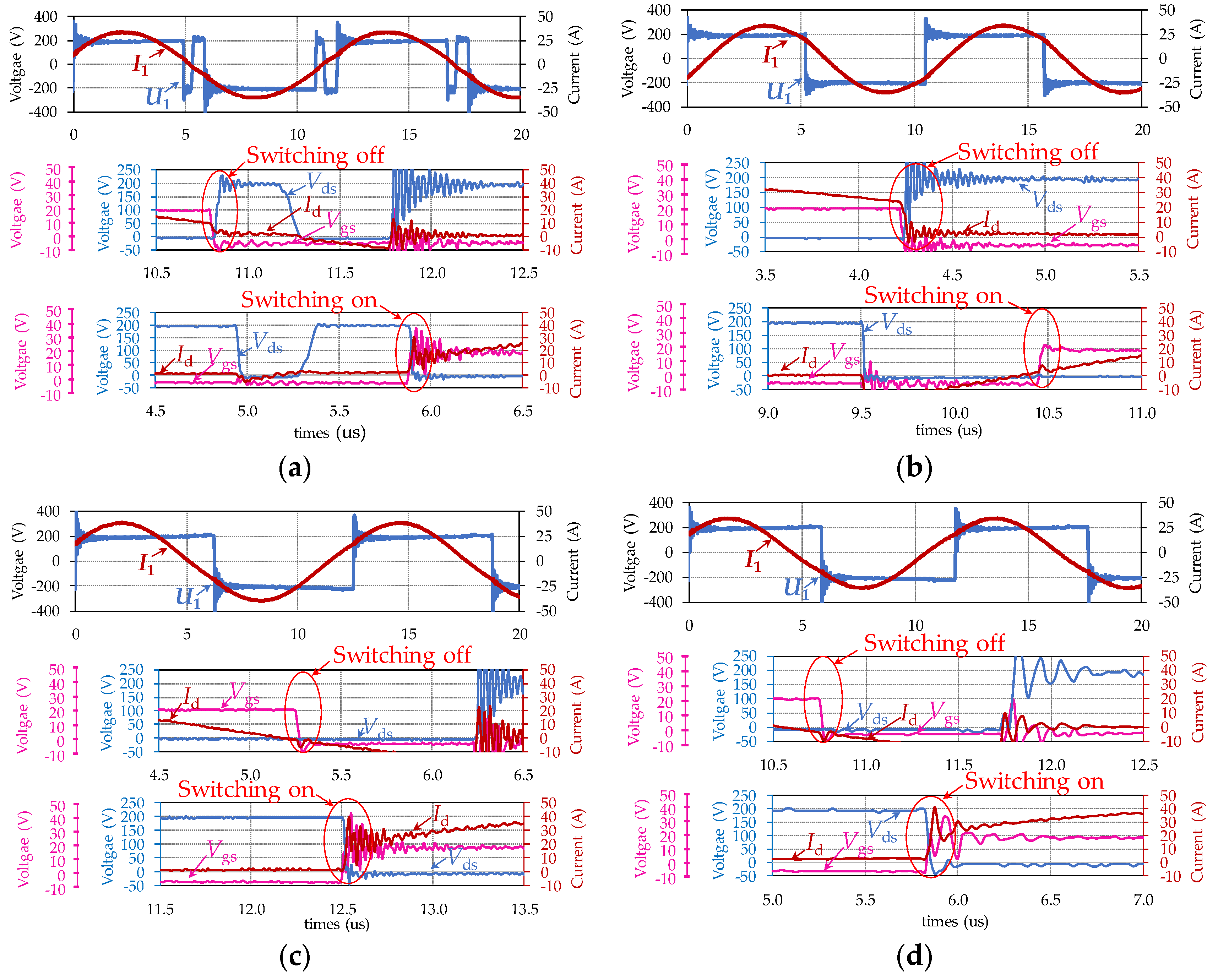
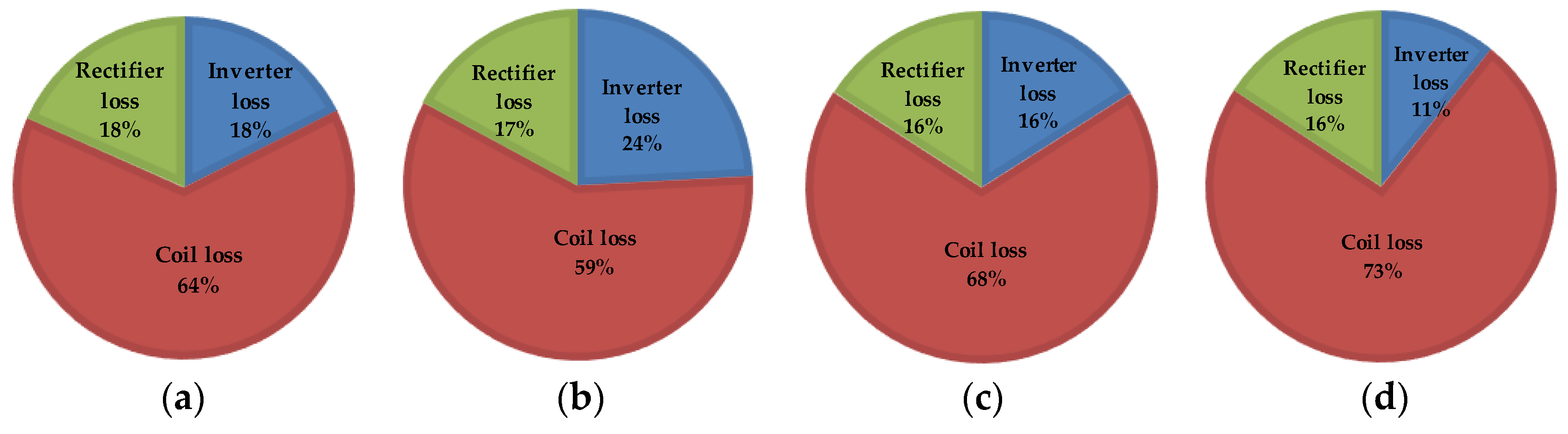
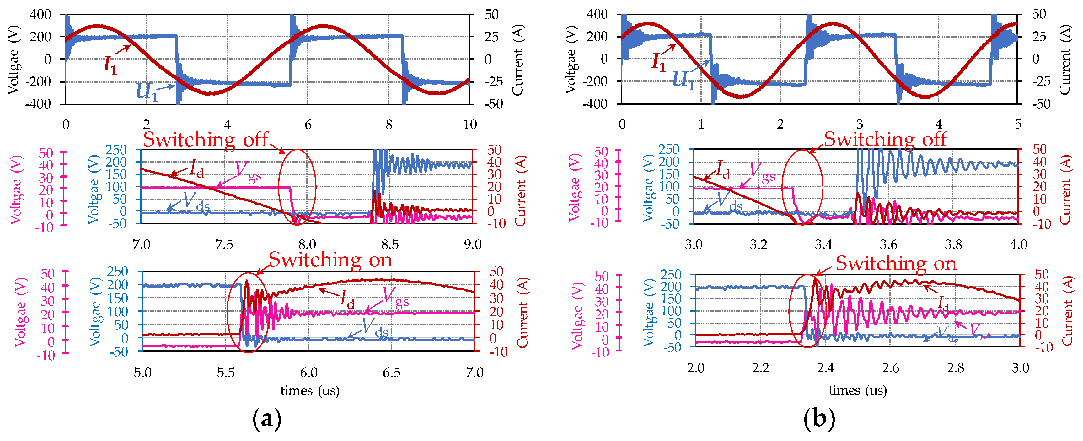
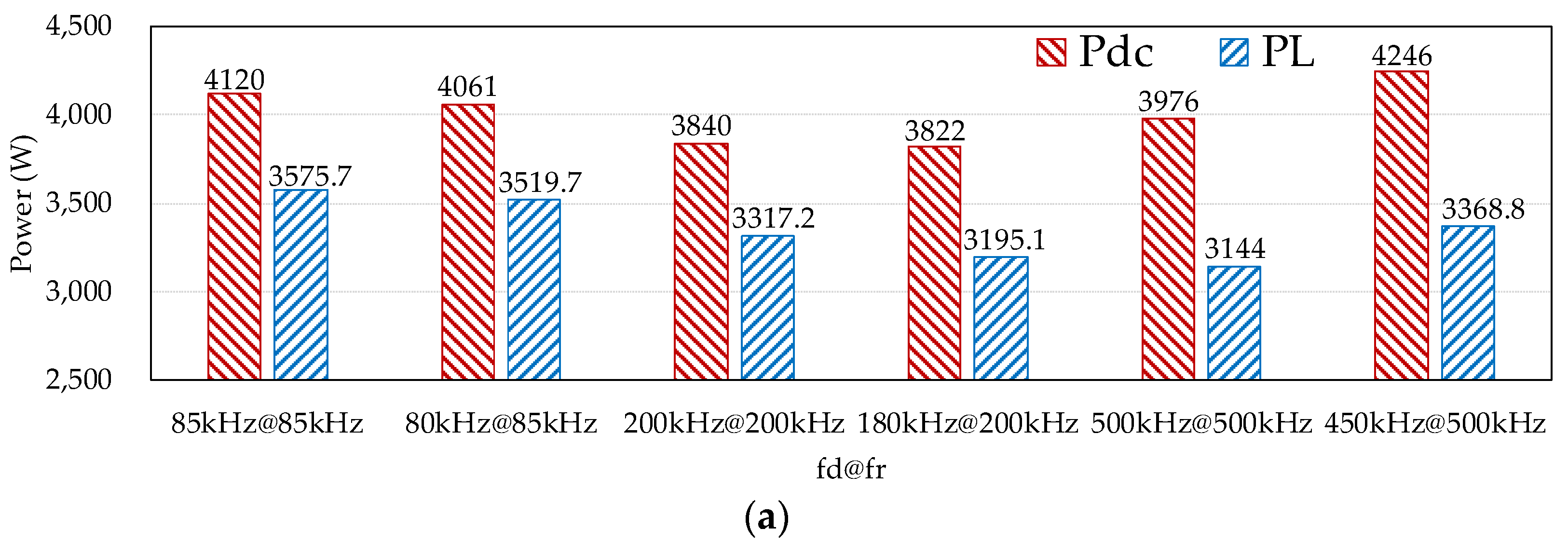
4.2. Experiment with Soft Switching

An 85 kHz WPT system is built up first as the baseline to validate the presented design method for soft-switching WPT system and make a comparison between different methods for realizing soft switching. With the coil specifications as listed in Table 1, the experiment with 85 kHz resonance is carried out with 200 V DC input voltage and 15 Ω load resistance. In the 85 kHz WPT system, the dead-time of the driving signals for the H-bridge inverter is set to be 1 μs. With Equations (13)–(25), in order to shift zero current point out of the dead-time, the minimum driving frequency which turns the input impedance into inductive is about 95 kHz and maximum driving frequency which turns the input impedance into capacitive is about 80 kHz. The voltage and current waveforms of the inverter output and the MOSFET are shown in Figure 9 for the previous four sets of experiment with the 85 kHz WPT system. It can be found from Figure 9a that, when the WPT system operates under resonant conditions, the output voltage and current waveforms of the inverter show good consistency with the theoretical analysis, and that the SiC MOSFETs operate in hard switching, which is also consistent with the analysis in Section 3.1. With methods proposed in Section 3.2, soft-switching on or soft-switching off can be realized by tuning the inverter input impedance to inductive or capacitive as shown in Figure 9b,c, respectively. The experimental waveforms show good consistency with the analysis in Section 3.1 about the analysis on the waveforms affected by the tuned driving frequency. The 95 kHz WPT system with 85 kHz driving frequency is also built up to verify the effects of soft switching on inverter efficiency. The result is shown in Figure 9d and it can be found out that soft-switching off is realized. Severe EMI (Electro-Magnetic Interference) generating ringing in the switching transients as shown in Figure 9 is a generally acknowledged problem for SiC devices and can be addressed by carefully optimizing the driving circuit and measurement techniques [23]. However, it does not affect the validation of the soft-switching methods.
It should be noticed that, when the driving frequency is tuned, the system efficiency and the output power will be both affected, so it is unfair to judge which method (increasing fd or decreasing fd) is better by the system efficiency or the inverter efficiency. Therefore, loss distribution in the system is used for analyzing the impacts of soft switching as shown in Figure 10.
Figure 10b shows that, when fd is higher than fr, even though soft-switching on is realized, the proportion of the inverter loss in the total loss is even higher than in hard switching mode, because the turn-off loss increases with the increase in fd. However, when fd is decreased (Figure 10c), the proportion of the inverter loss is reduced. This is not only contributed by the soft-switching off but also by the decreased turn-on switching losses because of a lower fd. Comparing Figure 10b with Figure 10c, even though the losses in the coil system can be reduced with soft-switching on, the loss reduction in the inverter is more significant in higher-frequency systems because heat dissipation is more difficult and important in the inverter than in the coils; besides, comparing Figure 10a with Figure 10d, when fd is the same, with soft-switching off, the proportion of the inverter loss is also reduced. Therefore, decreasing fd will be adopted for higher resonant frequency WPT systems which can not only eliminate the turn-off switching losses but also decrease the turn-on switching losses.
200 kHz and 500 kHz WPT systems are built up to validate that the soft-switching realization method can also be used in higher resonant frequency WPT systems. With the method for tuning the driving frequency, soft-switching off can be realised in both WTP systems as shown in Figure 11.
To analyze the impact of the design method for the coil system and the proposed soft-switching strategy on the performance of the WPT system, all the experimental results are presented in one figure as shown in Figure 12. It shows that, whether the WPT system operates at resonant condition or soft-switching condition, the output power can all be maintained at 3.3 kW. With soft-switching technology, the inverter efficiency is greatly improved at high operating frequencies, e.g., from 81.91% to 98.60% in the 500 kHz WPT system. It results in a small decrease in the overall efficiency, but higher inverter efficiency is critical for higher resonant WPT systems, as higher inverter efficiency can effectively reduce the volume of heatsink and the total WPT system, meanwhile, it can also provide a more safety operating environment for the high power and high frequency inverter. For WPT systems of tens of MHz, not only soft switching is required, the topology of the inverter also needs to be changed to enable higher driving frequency.
For the experiment results, the overall efficiency, the coil-to-coil efficiency and the inverter efficiency can be maintained at around 80%, 85% and 97% respectively with 3.3 kW output power in WPT systems with different resonant frequencies.

5. Conclusions

In this paper, a coil-system design method is proposed for WPT systems with given requirements on the DC input voltage & current, load resistance, and the resonant frequency. With the proposed coil design method, the WPT system can output similar DC input current/power by the same DC input voltage to power up the same load but at different resonant frequencies. It can effectively reduce the coil size and weight or improve the power transfer distance without scarifying the system power transfer capacity. Although the design method in this work is used to design a coil system according to its specific resonant frequency and input parameters, it is also suitable for satisfying requirements of output voltage, output power, and system efficiency, etc. For WPT systems with a higher resonant frequency, simple methods for tuning driving frequency are presented, which do not need to change the topology and the components of the WPT systems. Different tuning methods are compared considering the proportion of the inverter loss. A slight decrease in the driving frequency to realize soft-switching off is adopted in the WPT system with higher resonant frequency, which not only eliminates the turn-off switching losses but also decreases the turn-on switching losses. 85 kHz, 200 kHz and 500 kHz WPT systems are built up to verify the proposed coil design method and soft-switching techniques. With the proposed design method, all three WPT systems can achieve expected output power and overall efficiency with the same DC input voltage, load resistance and coupling coefficient. When the soft-switching technique is adopted in these WPT systems, the inverter efficiency is effectively improved, particularly in high-frequency WPT systems with slightly changing the output power and slightly decrease the system efficiency and overall efficiency.

Acknowledgments

This work was supported by the China Scholarship Council.

Author Contributions

Xu Liu designed the experiments and wrote the paper; Xibo Yuan and Jianjing Wang shared their experience and knowledge in power electronics; Jianjing Wang also helped analyze the switching transients and write this paper; Chonglin Wang analyzed the simulation data; Jianhua Liu helped to perform the analysis with constructive discussions.

Conflicts of Interest

The authors declare no conflict of interest.

References

  1. Covic, G.A.; Elliott, G.; Stielau, O.H.; Green, R.M.; Boys, J.T. The design of a contact-less energy transfer system for a people mover system. In Proceedings of the International Conference on PowerCon 2000 Power System Technology, Perth, Australia, 4–7 December 2000; Volume 1, pp. 79–84. [Google Scholar]
  2. Bosshard, R.; Muhlethaler, J.; Kolar, J.W.; Stevanovic, I. The η-α-Pareto front of inductive power transfer coils. In Proceedings of the IECON 2012 38th Annual Conference on IEEE Industrial Electronics Society, Montreal, QC, Canada, 25–28 October 2012; pp. 4270–4277. [Google Scholar]
  3. Khaligh, A.; Dusmez, S. Comprehensive topological analysis of conductive and inductive charging solutions for plug-in electric vehicles. IEEE Trans. Veh. Technol. 2012, 61, 3475–3489. [Google Scholar] [CrossRef]
  4. Wang, C.S.; Stielau, O.H.; Covic, G.A. Design Considerations for a Contactless Electric Vehicle Battery Charger. IEEE Trans. Ind. Electron. 2005, 52, 1308–1314. [Google Scholar] [CrossRef]
  5. Miller, J.; Daga, A. Elements of Wireless Power Transfer Essential to High Power Charging of Heavy Duty Vehicles. IEEE Trans. Transp. Electrif. 2015, 1, 26–39. [Google Scholar] [CrossRef]
  6. Li, S.; Li, W.; Deng, J.; Nguyen, T.D.; Mi, C.C. A Double-Sided LCC Compensation Network and Its Tuning Method for Wireless Power Transfer. IEEE Trans. Veh. Technol. 2015, 64, 2261–2273. [Google Scholar] [CrossRef]
  7. Pantic, Z.; Bai, S.; Lukic, S.M. ZCS LCC-compensated resonant inverter for inductive-power-transfer application. IEEE Trans. Ind. Electron. 2011, 58, 3500–3510. [Google Scholar] [CrossRef]
  8. Samanta, S.; Rathore, A.K.; Member, S. A New Current-Fed CLC Transmitter and LC Receiver Topology for Inductive Wireless Power Transfer Application: Analysis, Design, and Experimental Results. IEEE Trans. Transp. Electrif. 2015, 1, 357–368. [Google Scholar] [CrossRef]
  9. Onar, O.C.; Chinthavali, M.; Campbell, S.; Ning, P.; White, C.P.; Miller, J.M. A SiC MOSFET based inverter for wireless power transfer applications. In Proceedings of the 2014 Twenty-Ninth Annual IEEE Applied Power Electronics Conference and Exposition (APEC), Fort Worth, TX, USA, 16–20 March 2014; pp. 1690–1696. [Google Scholar]
  10. Chan, T.S.; Chen, C.L. LLC resonant converter for wireless energy transmission system with PLL control. In Proceedings of the IEEE International Conference on ICSET 2008 Sustainable Energy Technologies, Singapore, 24–27 November 2008; pp. 136–139. [Google Scholar]
  11. Tian, J.; Hu, A.P. A DC-voltage Controlled Variable Capacitor for Stabilizing the ZVS Frequency of a Resonant Converter for Wireless Power Transfer. IEEE Trans. Power Electron. 2017, 32, 2312–2318. [Google Scholar] [CrossRef]
  12. Lin, F.Y.; Covic, G.A.; Boys, J.T. Evaluation of Magnetic Pad Sizes and Topologies for Electric Vehicle Charging. IEEE Trans. Power Electron. 2015, 30, 6391–6407. [Google Scholar] [CrossRef]
  13. Lu, F.; Member, S.; Zhang, H.; Member, S.; Hofmann, H. A High Efficiency 3.3 kW Loosely-Coupled Wireless Power Transfer System Without Magnetic Material. In Proceedings of the 2015 IEEE Energy Conversion Congress and Exposition (ECCE), Montreal, QC, Canada, 20–24 September 2015; pp. 2282–2286. [Google Scholar]
  14. Shamseh, M.B.; Yuzurihara, I.; Kawamura, A. A 3.2-kW 13.56-MHz SiC Passive Rectifier with 94.0% Efficiency Using Commutation Capacitor. IEEE Trans. Power Electron. 2016, 31, 6787–6791. [Google Scholar]
  15. Jeong, S.; Jung, J.; Kim, K.A.; Kim, J. Analytical investigation of optimal wireless power transfer topology for electric vehicles. In Proceedings of the 2015 IEEE PELS Workshop on Emerging Technologies: Wireless Power (WoW), Daejeon, Korea, 5–6 June 2015; pp. 1–5. [Google Scholar]
  16. Wang, Y.; Yao, Y.; Liu, X.; Xu, D. S/CLC Compensation Topology Analysis and Circular Coil Design for Wireless Power Transfer. IEEE Trans. Transp. Electrif. 2017, 3, 496–507. [Google Scholar] [CrossRef]
  17. Chan, H.; Cheng, K.; Sutanto, D. A Simplified Neumann’S Formula for Calculation of Inductance of Spiral Coil. In Proceedings of the Eighth International Conference on (IEE Conf. Publ. No. 475) Power Electronics and Variable Speed Drives, London, UK, 18–19 September 2000; pp. 18–19. [Google Scholar]
  18. Duong, T.P.; Lee, J.W. A dynamically adaptable impedance-matching system for midrange wireless power transfer with misalignment. Energies 2015, 8, 7593–7617. [Google Scholar] [CrossRef]
  19. Waffenschmidt, E.; Staring, T. Limitation of inductive power transfer for consumer applications. In Proceedings of the 2009 EPE’09 13th European Conference on Power Electronics and Applications, Barcelona, Spain, 8–10 September 2009; pp. 1–10. [Google Scholar]
  20. Niu, W.Q.; Chu, J.X.; Gu, W.; Shen, A.D. Exact Analysis of Frequency Splitting Phenomena of Contactless Power Transfer Systems. IEEE Trans. Circuits Syst. I Regul. Pap. 2013, 60, 1670–1677. [Google Scholar] [CrossRef]
  21. Sallan, J.; Villa, J.L.; Llombart, A.; Sanz, J.F. Optimal Design of ICPT Systems Applied to Electric Vehicle Battery Charge. IEEE Trans. Ind. Electron. 2009, 56, 2140–2149. [Google Scholar] [CrossRef]
  22. Moon, S.; Kim, B.C.; Cho, S.Y.; Ahn, C.H.; Moon, G.W. Analysis and Design of a Wireless Power Transfer System With an Intermediate Coil for High Efficiency. IEEE Trans. Ind. Electron. 2014, 61, 5861–5870. [Google Scholar] [CrossRef]
  23. Walder, S.; Yuan, X. Effect of load parasitics on the losses and ringing in high switching speed SiC MOSFET based power converters. In Proceedings of the 2015 IEEE Energy Conversion Congress and Exposition (ECCE), Montreal, QC, Canada, 20–24 September 2015; pp. 6161–6168. [Google Scholar]
Figure 1. Wireless power transfer (WPT) system: (a) Whole system; (b) simplified model.
Energies 11 00007 g001
Figure 2. Effect of resonant frequency on the WPT system performance: (a) fixed coil-to-coil distance and varied load resistance; (b) fixed load resistance and varied coil-to-coil distance.
Energies 11 00007 g002
Figure 3. Elevation view of a flat spiral coil.
Energies 11 00007 g003
Figure 4. Waveforms of U1 & I1 and gate signals of the inverter in a full switching cycle with fd = fr.
Energies 11 00007 g004
Figure 5. Waveforms of U1 & I1 and gate signals of the inverter in a full switching cycle with fd > fr.
Energies 11 00007 g005
Figure 6. Waveforms of U1 & I1 and gate signals of the inverter in a full switching cycle with fd < fr.
Energies 11 00007 g006
Figure 7. Experimental platform of the WPT system.
Energies 11 00007 g007
Figure 8. Three resonant WPT systems experiment results: (a) input and output power; (b) efficiency.
Energies 11 00007 g008
Figure 9. Experimental waveforms of the 85 kHz WPT system: (a) 85 kHz@85 kHz; (b) 95 kHz@85 kHz; (c) 80 kHz@85 kHz; (d) 85 kHz@95 kHz.
Energies 11 00007 g009
Figure 10. Loss distribution of the 85 kHz WPT system: (a) 85 kHz@85 kHz; (b) 95 kHz@85 kHz; (c) 80 kHz@85 kHz; (d) 85 kHz@95 kHz.
Energies 11 00007 g010
Figure 11. WPT system of higher resonant frequency with soft switching: (a) 180 kHz@200 kHz y; (b) 450 kHz@500 kHz.
Energies 11 00007 g011
Figure 12. Experimental performance of the three systems: (a) power; (b) efficiency.
Energies 11 00007 g012aEnergies 11 00007 g012b
Table 1. Design parameters for coil systems with three different resonant frequencies.
ParameterSymbolValueValueValueUnit
Designed resonant frequencyfr85200500kHz
Expected mutual inductanceM1218.727.963.18μH
Designed coupling coefficientk0.30.30.3-
Expected coil self-inductanceL62.426.510.6μH
Expected compensation capacitanceC56.2249.6nF
Designed out radius router290290190mm
Designed channel width p161616mm
Designed coil turnsN1665-
Actual coil self-inductanceLa64.029.3912.0μH
Actual coil resistanceRL156.748.225.9
Actual compensation capacitanceCa54218.44nF
Actual coil to coil distanced150140100mm
Actual coupling coefficientka0.2810.270.27-
Actual mutual inductanceM12a17.987.933.24μH
Dead-timet10.50.2μs

