Poly(imide-co-siloxane) as a Thermo-Stable Binder for a Thin Layer Cathode of Thermal Batteries
by

Ilwhan Oh
1, 
Jaeyoung Cho
1,
Kwansu Kim
1,
Jaehwan Ko
2,
Haewon Cheong
3,
Young Soo Yoon
2,* and
Hyun Min Jung
1,* 1
Department of Applied Chemistry and Department of IT Convergence Engineering, Kumoh National Institute of Technology, Gumi 730-701, Korea
2
Department of Chemical and Biological Engineering, Gachon University, Seongnam 13120, Korea
3
Convergence Technology Research Directorate, Agency for Defense Development, Daejeon 305-600, Korea
*
Authors to whom correspondence should be addressed.
Energies 2018, 11(11), 3154; https://doi.org/10.3390/en11113154
Submission received: 23 October 2018
/
Accepted: 10 November 2018
/
Published: 14 November 2018
(This article belongs to the Section D: Energy Storage and Application)
Abstract
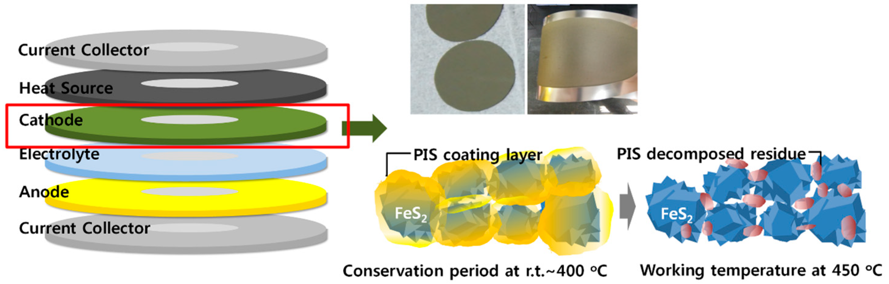
:The polymer binder, poly(imide-co-siloxane) (PIS), was synthesized and applied to form a thin cathode layer of composites for a thermal battery that has an unusually high operating temperature of 450 °C. The PIS was prepared through cross-linking of the polyimide with polysiloxane. The morphology of FeS2/PIS composites showed that FeS2 particles was coated with the PIS cross-linked gel. The FeS2/PIS composites enabled to fabricate mechanically stable thin cathode layer that was 10–20% of the thickness of a conventional pellet-type cathode. The FeS2/PIS composites were stable up to 400 °C and maintained their morphology at this temperature. PIS coating layers decomposed at 450 °C, and a new residue was generated, which was observed by transmission electron microscopy, and the compositional change was analyzed. The FeS2/PIS composites showed enhanced thermal stability over that of FeS2 in thermogravimetric analysis. The thermal battery with the PIS polymer binder showed a 20% discharge capacity increase when compared to a conventional pellet-type cathode.
1. Introduction
Recently, much attention has been drawn to the functional materials for energy storage devices that are suitable for improving performance and efficient manufacturing processes [1,2]. Among the various energy storage devices, thermal batteries have had little progress in their applied materials over the long history of development due to their high operating temperature up to 450 °C. The thermal battery is a primary battery that uses a pyrotechnic source to raise the temperature of a battery stack to the operating temperature, and they utilize molten salts (such as LiCl–KCl) as the electrolyte, which melt and start Li-ion transfer at an operating temperature. Li–Si is used as the anode, and FeS2 (pyrite) is used as the cathode [3,4]. Thermal batteries are primarily used for emergency power sources and military purposes (for example, missiles, ordnances, and nuclear weapons) due to their exceptional mechanical robustness, reliability, and long shelf life [4,5,6,7,8]. Optimization of the molding and manufacturing process of the individual components of thermal batteries is very important because the mechanical strength and reliability of thermal batteries are critical for emergency and military applications [9].
In general, the constituent units of thermal batteries are produced, through a pressing process, in the form of pellets that are several hundreds of micrometers thickness. However, especially in the cathode layer, the pellets that are produced through such a process are molded to be thicker than the optimal thickness, in order to maintain their mechanical strength. On the other hand, an inorganic binder, MgO, can be added for the reinforcement of the brittle FeS2 layer to prevent the cracking of the layers that cause the problem of low utilization of the electrode material. When the thickness of an electrode pellet is above a certain level, the electrode utilization and conductivity are significantly reduced, which can lead to a reduction in the capacity of the entire thermal battery. In order to solve such a problem, it is important to develop a manufacturing process that produces a thinner cathode with adequate mechanical strength [10,11]. However, for the cathode layer to optimize the electrochemical performance of the cell, the materials and processes that can be applied are very limited due to a high operating temperature.
To maintain the mechanical strength and to control the thickness of the electrode, a polymer binder is generally used in the conventional battery field [12,13,14]. Particularly in the field of lithium-based secondary batteries, polyvinylidenefluoride (PVDF) is currently the most widely utilized for the fabrication of both cathodes and graphite anodes [15,16]. In addition, polyacrylonitrile (PAN) [17] and polyacrylic acid (PAA) binders [18] were introduced as alternative binders. All of these polymeric binders are being applied at battery operating temperatures that are lower than 80 °C and at cathode process temperatures that are lower than 150 °C. PAN and PAA have a low glass transition temperature (101–105 °C) and a low heat deflection temperature (70 °C), and pyrolysis begins at around 200 °C. Especially, PVDF, which is used in lithium ion batteries, has a limitation on the application of thermal batteries due to the problem of a low melting point (160 °C). Therefore, they cannot be used for applications of thermal batteries with operating temperatures of at least 400 °C and high processing temperatures of 250 °C for cathode molding. The utilization of polyimide as a polymer binder can meet these high-temperature operations and manufacturing process needs. In the development of lithium secondary batteries, the results of the application of polyimide as a cathode binder material have been reported [19,20,21,22]. Recent studies have shown that Li-ion battery performance is greatly improved due to the binding and coating properties of polyimide on the cathode materials [23]. Polyimide has excellent heat resistance, with a decomposition temperature that is greater than 400 °C. It also has good mechanical and chemical properties, and it is expected to be an exceptional polymer binder for the cathodes of thermal batteries.
Recently, we reported the fabrication of a thin cathode film for thermal batteries using novel binder materials and a slurry casting process [10,11]. The role of the binder is important for the slurry casting process and stable electrode formation. Polymeric binders are expected to be more effective for the fabrication of thinner cathodes because of the improved binding effect of particles, which lead to improved full-cell performances. However, conventional polymeric binders are limited in this application due to their poor thermostability.
In this study, we applied polyimide as a binder for the cathode of a thermal battery, to overcome the limitations of existing polymer binders. Poly(imide-co-siloxane) (PIS), which is a copolymer of imide and siloxane, was designed and synthesized to form a cross-linked gel; it was then tested as a binder for cathode molding. We show that a thin cathode film with mechanical stability can be formed with the PIS binder. Compared with the pellet-type FeS2 cathode, the slurry-cast FeS2 cathode with the PIS binder exhibited enhanced a discharge capacity. This proves that the novel PIS binder was effective for fabricating a thin cathode layer through the slurry casting process without degrading the electrical properties of the FeS2 film. This resulted in improved mechanical and electrical properties, and thus, a higher capacity of the thermal battery was obtained.
2. Materials and Methods
2.1. Materials and Instruments
4,4′-(Hexafluoroisopropylidene) diphthalic anhydride (6-FDA), 2,2′-bis(trifluoromethyl)-4,4′-diaminobiphenyl (TFDB), and 3,5-diaminobenzoic acid (DABA) were purchased from the Aldrich Chemical Co. (Sigma-Aldrich, St. Louis, MO, USA) and used as received. N,N-Dimethylformamide (DMF), tetrahydrofuran (THF), and acetone were purchased as reagent grade and purified by passing them through a purification column consisting of alumina and a molecular sieve. (Glass Contour). The polysiloxane (XIAMETER® OFX-8040 Fluid, Dow Corning, Midland, MI, USA) was used as received. The FeS2 powders (mean size of 98 µm, 99%, Linyi, China) were used as the active material. The molecular structure of the synthesized PI was characterized by 1H- and 13C-nuclear magnetic resonance (NMR; Bruker Advance 400 MHz, Bruker, Seongnam-si, Korea). A field emission scanning electron microscope (FE SEM; MAIA 3, TESCAN, Brno, Czech Republic) and transmission electron microscope (TEM; JEM-2100, JEOL, Tokyo, Japan) were used to identify the morphology of the FeS2/PIS composites. Surface analysis was conducted using X-ray photoelectron spectroscopy (XPS) (K-Alpha, ThermoFisher, Waltham, MA, USA) with an Al Kα X-ray source at 15 kV. The thermal stability of the synthesized PI was measured with thermogravimetric analysis (TGA; Auto-TGA Q500, TA Instruments, New Castle, DE, USA).
2.2. Preparation of Polyimide
TFDB (19.1 g, 59.6 mmol), 6-FDA (33.1 g, 74.5 mmol), and DABA (2.26 g, 14.9 mmol) were dissolved in 140 mL of DMF and stirred for 5 h at 0 °C under nitrogen. After the reactants were further reacted at room temperature (r.t.) for 17 h, acetic anhydride (40 mL) and pyridine (29 mL) were added to the reaction mixture. After a 24 h reaction at 80 °C, the resultant polyimide (PI) solution was cooled to r.t. and added into a beaker filled with distilled water to precipitate the PI. The precipitated PI was filtered and washed with water and ethanol. The resultant PI was dried at 120 °C for 24 h under vacuum.
2.3. In Situ PIS Gel Formation and Preparation of FeS2/PIS Cathode Composites
The prepared PI was dissolved in THF and combined with FeS2 in an acetone slurry. The polysiloxane was added to the resulting mixture; the total amount of PI and polysiloxane was 10 wt % in the FeS2 active materials, and the PI-to-polysiloxane weight ratio was 1:2. The ball milling process was carried out twice (24 h each) to maximize the dispersion of the FeS2 powder before and after adding the binder. The balls used in the ball milling process were zirconia with diameters of 10 mm and 5 mm at a 1:1 ratio. After the ball milling process, the bubbles contained in the slurry were removed in a vacuum chamber. The prepared slurry was coated on a 50 μm thick SUS (stainless steel) plates using the doctor blade. The resulting cathode film on SUS plate were dried at 70 °C for 1 h and 250 °C for 2 h.
2.4. Thermal Battery Cell Fabrication and Discharge Measurements
The dried samples were cut into circular-shaped pieces, with a diameter of 56.2 mm, to assemble them as the cathode in a thermal battery. The assembled single-cell diagram is described in Figure 1. The single cells were discharged at 500 °C while applying a consecutive pulse current profile (10 A, 4.5 s → 0 A, 0.5 s). The cell discharge was terminated when the voltage dropped below 1.3 V.
2.5. Electrical Conductivity Measurement
The vertical conductivity of the prepared FeS2/PIS thin film was measured. A silver electrode was deposited onto the FeS2/PIS thin film, formed on the SUS substrate, using a shadow mask and a thermal evaporator. The thermal evaporator (JVR-72S, Jvac., Yangju-si, Korea) equipped with thickness detector (STM-100/MF, Sycon Instruments, East Syracuse, NY, USA) was used. The Ag deposition rate was 1 Å/s, and the total operating time was 800 s, to make a 80 nm thick Ag layer on the FeS2/PIS thin film. Current–voltage characteristics was measured on this sample using a potentiostat (Autolab PGSTAT302N, Metrohm, Herisau, Switzerland) that was connected on the Ag layer and SUS plate through the probe tips.
2.6. Electrical Properties of the FeS2/PIS Cathode Layer
The electrical properties of the prepared FeS2/PIS thin layer cathode were measured. The vertical conductivity of the prepared thin-film sample was measured using sharp probes in a probe station.
3. Results and Discussion
3.1. Synthesis of Polyimide and the Formation of Cross-Linked PIS
PIS was formed by cross-linking polyimide and polysiloxane at high temperatures. PIS was composited with cathode material FeS2 as a high heat-resistant binder to form a thin cathode layer. The applied polyimide was polymerized with a combination of 6-FDA, TFDB, and DABA as monomers (Scheme 1).
The polyimide product was confirmed by 1H, 13C-NMR (Figure S1a,b) and FT-IR (Figure S2). The poly(imide-co-siloxane) to be formed in this study was based on a copolymer formation in which the polysiloxane moiety was grafted onto the polyimide main chain. For this purpose, the polyimide was prepared with monomers containing DABA to introduce a carboxyl group that was capable of an amide bonding reaction with aminosiloxane. The combination of the 6-FDA and TFDB monomer components allowed for the solubility of polyimide in organic solvents such as THF, with mixing with FeS2 in solution.
Polysiloxane is a liquid polymer with a terminal amine group, which forms a gel by mixing with a polyimide that contains carboxyl groups. In this stage, at room temperature, gelation proceeded through the formation of acid–base salts of amino and carboxyl groups. In situ gelation at the mixing stage with the FeS2 particles had several advantages. The liquid polysiloxane and polyimide solution allowed for perfect, uniform mixing with the FeS2 particles and the solid composite formed as the gelation progressed. We found that 1–3 h was required for complete gelation by the mixing of the two components. Due to the slow gelation of two components, the FeS2 particles were uniformly mixed with the liquid polyimide and polysiloxane at the beginning of the mixing process. The gelation process then yielded a mechanically stable cathode composite layer. The gelation was involved in the acid–base complexation of the amine groups in the polysiloxane with the carboxyl groups in the polyimide. This gel formed as chemically and thermally stable grafting PIS through an amide bond formation at a process condition of 250 °C. Unlike the polysiloxane and polyimide, the PIS that was formed after the high-temperature treatment was insoluble in organic solvents, and it did not show melting at high temperatures.
3.2. Formation of the Cathode Thin Layer and Its Thermal Properties
A polysiloxane/polyimide mixture was added to the FeS2 at 10 wt % and the slurry was cast on a current collector (SUS plate) by the doctor blade method. During this process, the thickness of the casted cathode composites could be reduced to 50–100 μm at a level where the thin layer was stably maintained. This thickness was 20% to 10% of the thickness of a typical pelletized FeS2 electrode of 500 μm. When a pellet is manufactured by compression without a polymer binder, the thickness of the electrode must be at least 500 μm to maintain its shape due to the characteristics of the brittle FeS2 layer. The ability to reduce the thickness of the FeS2 electrode with low electrical conductivity results in very favorable electron transport in the cathode layer. The application of the polymeric binder allowed for slurry casting, which made the process uniform and convenient, and also reduced the thickness of brittle FeS2. A bending test (4-point bending with 198 kgf pressure) was performed to confirm the stability of the 100 µm thick FeS2/PIS composite cathode. It showed a 6.2 mm displacement until the occurrence of a crack, which represents a greater stability against bending when compared with the 0.8 mm displacement with the binder-free sample. The samples used were freestanding samples that were removed from the SUS plates. The cathode composite layer that was attached to the SUS plate exhibited greatly increased the stability and maintained the layer without cracking, even with a large curvature 360° bending (Figure S3).
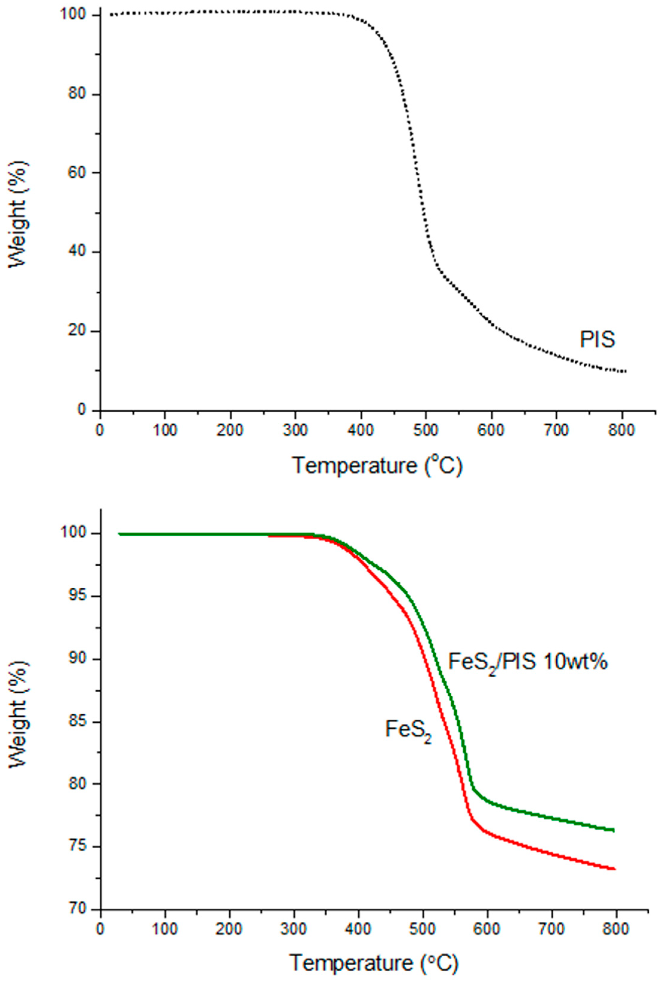
In order to form thin-layer cathode composites by the slurry casting process after the mixing of FeS2 and PIS binder, it was necessary to completely remove the solvent component through high-temperature treatment at 250 °C or higher. Typical polymer binders cause decomposition reactions at these high-temperature conditions, and they show brittle characteristics after molding. Moreover, in thermal batteries with a high operating temperature of 400 °C or higher, the application of a binder that lacks high thermal stability in a thin layer cathode can cause a sudden failure, due to the collapse of the cathode layer. The TGA analysis of the PIS showed that the decomposition of the binder component started at 400 °C and fully decomposed at 500 °C (Figure 2). Considering that the operating temperature of a thermal battery is in the range of 450 to 500 °C, it is presumed that the binder component is maintained at the early stage, and decomposition proceeds considerably during the operation of the thermal battery.
The results of the comparison between the thermal degradation tendencies of pure FeS2 and the FeS2/PIS composites are noteworthy. The FeS2 slowly decomposed when the temperature exceeded 400 °C. Above 500 °C, the FeS2 showed a rapid change and decomposed at 570 °C, represented by a 25% weight loss. A similar pattern also appeared for the FeS2/PIS composites, but they showed a slower progression of degradation. They showed a weight loss of 22%, up to the point where the decomposition stabilized at 570 °C, consequently giving a higher thermal stability to the FeS2 through the combination with PIS. In particular, the total amount of decomposition of the FeS2/PIS composites included the decomposition of the 10 wt % PIS binder, so that the actual amount of FeS2 decomposition was further reduced. The effect of thermal stability at the operating temperature range of 450–500 °C may have had a great influence on the performance of the battery. This can be attributed to the morphology of the composites between the PIS and FeS2 particles, which was confirmed by electron microscopy.
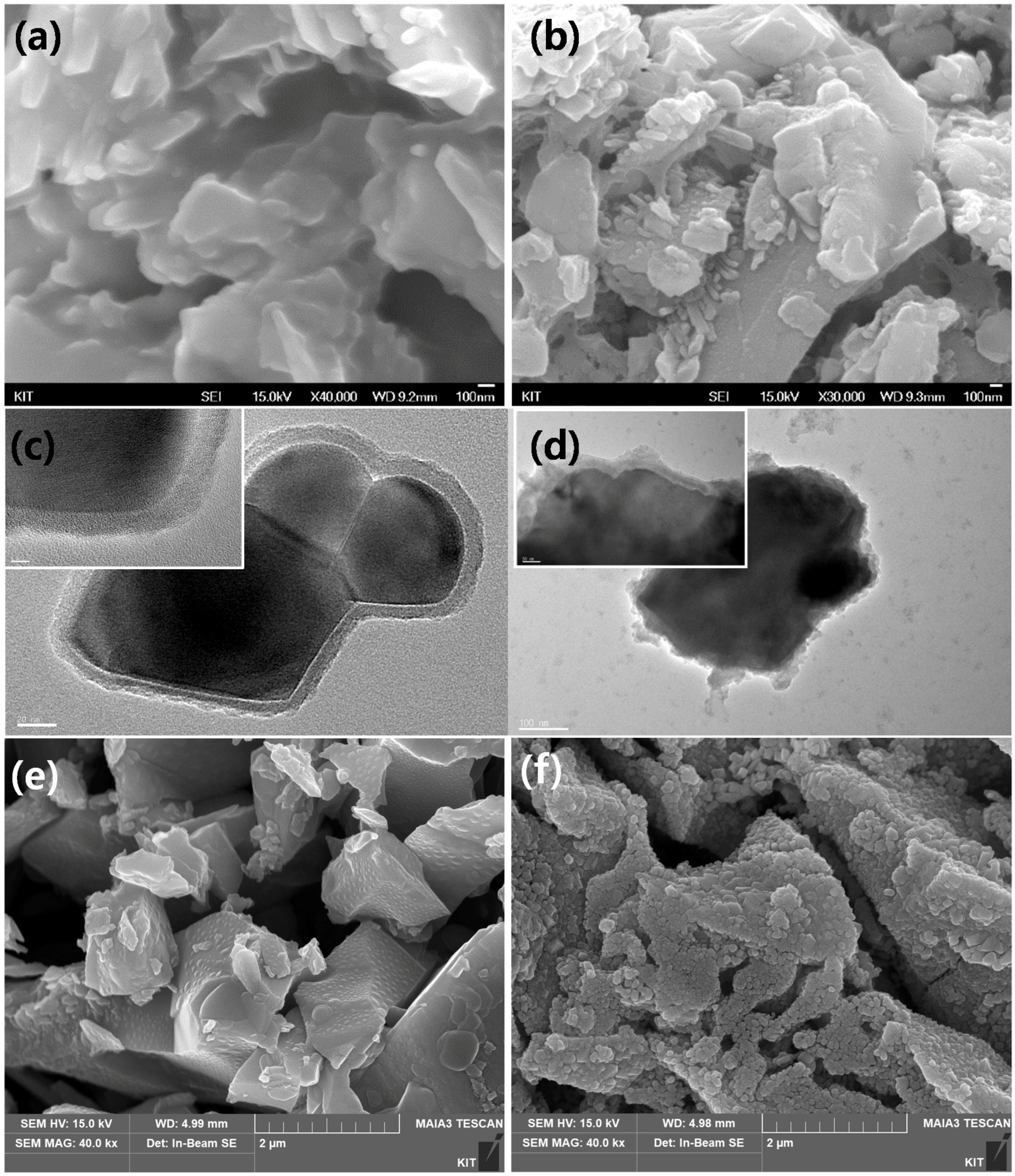
The FeS2/PIS composites as formed at 250 °C, as well as the changes that occurred at 450 °C, were observed by SEM and TEM (Figure 3). The images revealed that the FeS2/PIS composites particles were uniformly coated by the PIS layer (Figure 3a). The detailed structure of each particle was observed through a TEM image, showing that a PIS layer was formed on the surface of particles with a thickness of about 10 to 20 nm (Figure 3c). The PIS coating was not formed on the individual particles of FeS2 but it appeared to be attached to the surface of the agglomerates of FeS2 particles. In the image after 1 h at 450 °C, the majority of the PIS layer that covered the surface disappeared (Figure 3b), and residual components appeared (Figure 3d). Considering that the PIS binder coating layer was stable at around 400 °C and that decomposition was observed after this in the TGA, the observation of decomposition in the microscopy at 450 °C was in good agreement with the TGA. We also observed that more than 30 wt % of the PIS residue remained in the temperature range of 450–500 °C, which could affect surface and binding of the FeS2 particles. In pellet-type FeS2 without PIS, changes in other aspects were apparent at high temperature treatment (Figure 3d,e). After the heat treatment at 450 °C, the surface of the FeS2 particles was greatly increased in roughness, and the entire surface of the FeS2 particles was split into small pieces with a size of 100–200 nm. The original particle structure of a few microns in size remained, but this change in the surface of each particle appeared to have begun FeS2 pyrolysis at the surface. This was comparable to the change in FeS2/PIS composites where the particle surface was relatively well retained, which was consistent with the TGA results showing a lowered thermal stability of FeS2 than that of the FeS2/PIS composites. These results were found to be highly related to the electrochemical properties to be discussed later.
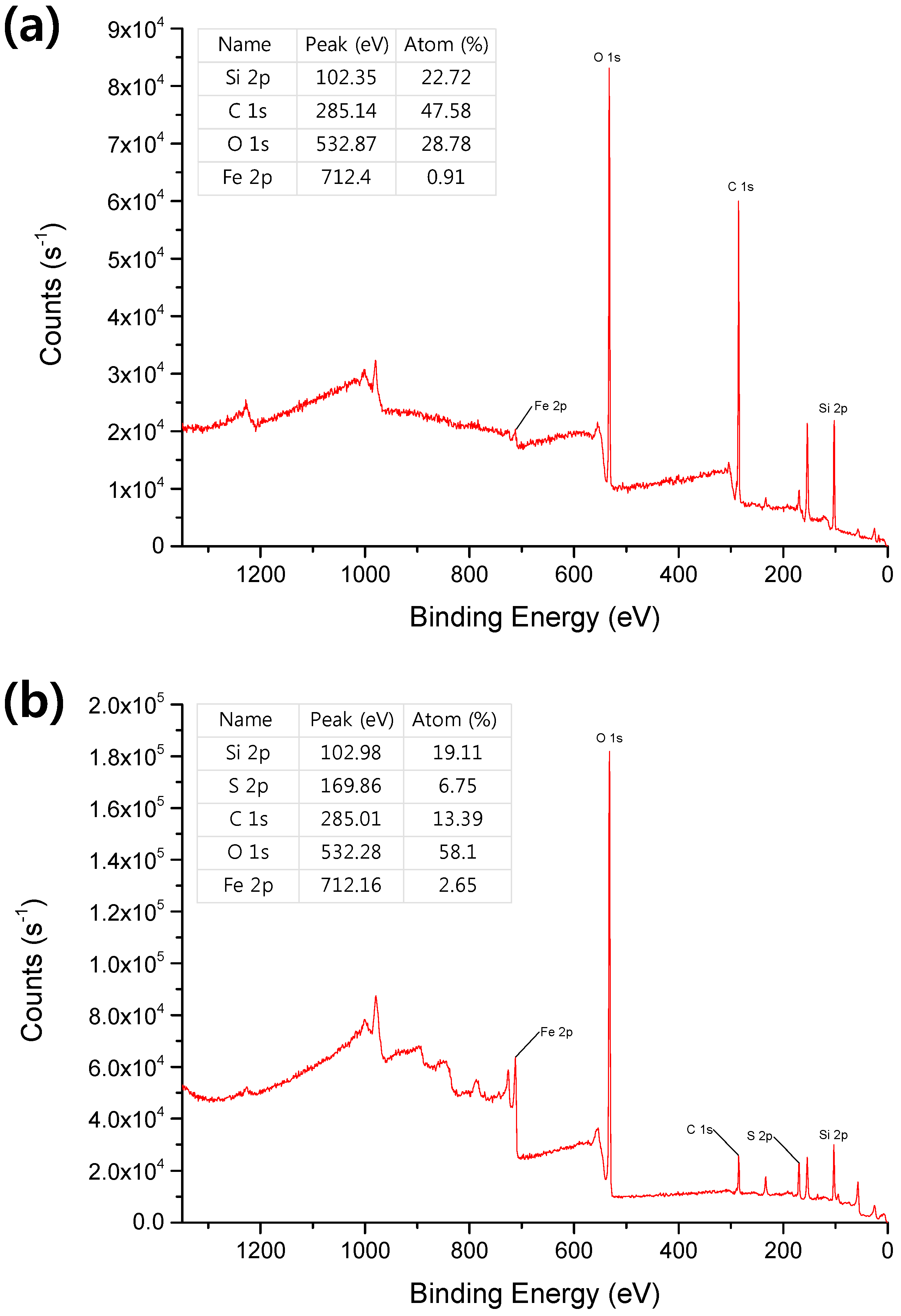
The compositional changes on surface of the FeS2 after decomposition at 450 °C were investigated by XPS analysis (Figure 4). The main changes in the composition were a rapid decrease of the carbon component and a relative increase of the Fe component. The decrease of the carbon signifies the decomposition of the carbon skeleton of PIS, and a small portion of carbon backbone was presumed to form a residue by carbonization. On the other hand, the relative amount of Si remained unchanged, unlike the decrease of C. This suggests that the siloxane moiety was retained in the form of SiO2, rather than being removed by volatile degradation. This was consistent with the TEM observation that a large portion of the PIS layer that covered the FeS2 particle disappeared, but a partially covering residue remained on the surface. We believe that the increase in the relative amounts of the Fe were due to the increase of the Fe exposed to the surface.
The morphology of the FeS2/PIS composites is presumed to influence the electrical properties of the cathode layer. The morphology of the PIS binder in the composites up to 400 °C served to provide the mechanical stability of the cathode layer. Decomposition in the 450 °C thermal condition minimized the electrical insulation in the operating temperature range of the thermal battery, and allowed the FeS2 particles to exhibit an appropriate level of connectivity. In addition, the binding effect between the particles through the residue, following decomposition, could improve the cathode efficiency by preventing the electrical disconnection between particles in the cathode layer.
3.3. Electrical Properties of the FeS2/PIS Cathode Layer
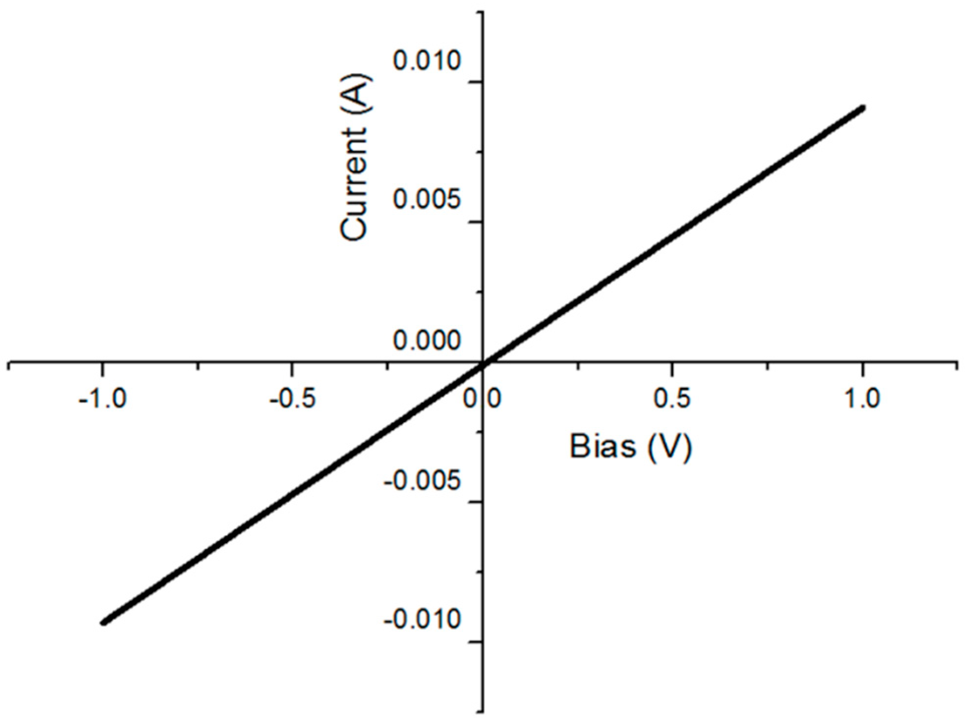
The electrical properties of the prepared FeS2/PIS thin layer cathode were measured. The conductivity of the composites material possibly decreased when the PIS binder, which is much lower in electrical conductivity than FeS2 semiconductor, was added. The conductivity of the electrode material is an important factor for the performance of the full cell. Figure 5 shows the results of the vertical conductivity measurement of the FeS2/PIS thin film. The results show that the FeS2/PIS thin film exhibited a linear current–voltage relationship, as expected for a simple resistor. The measured conductivity of the thin film was 0.63 mS/cm. This indicates that even though the semiconducting FeS2 was mixed with insulating PIS, the composites film exhibited a considerable conductivity, which is important for the efficient operation of the full thermal battery.
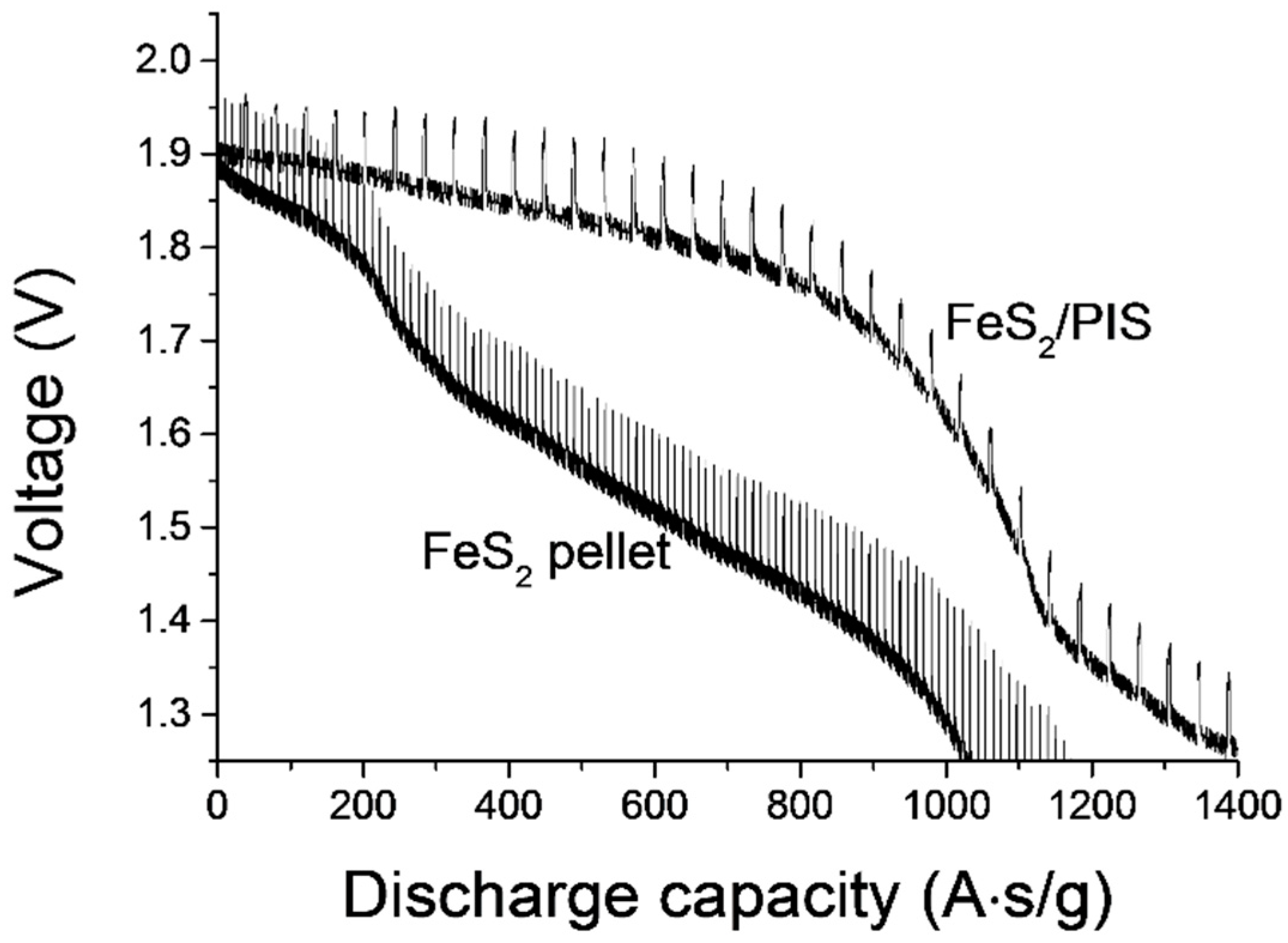
The battery discharge capacity of the fabricated FeS2/PIS thin layer cathode was measured. The results were compared with those for the FeS2 pellet-type cathode. In the battery capacity measurement, a pulse current of 10 A for 4.5 s at an interval of 0.5 s was applied. The discharge was terminated when the voltage dropped below 1.3 V. The FeS2/PIS thin-layer cathode and pellet-type FeS2 cathode exhibited discharge capacities of 1283 A∙s/g and 1002 A∙s/g, respectively (Figure 6). The FeS2/PIS thin layer cathode showed greater than a 20% increase in discharge capacity over the pellet-type FeS2 cathode. From these results, we conclude that the application of the PIS binder does not interfere with the operation of the thermal battery. This resulted in no electrical insulation of the FeS2 particles by the binder at the operating temperature, and no issues caused by decomposition. More importantly, the application of the PIS binder enabled a fabrication process that allowed for mechanical stability of the cathode composites at a 1/5 thickness level, compared to conventional method. A reduced cathode thickness could increase the efficiency of the cathode by decreasing its resistance in the electric current collecting, and this effect resulted an increase of the capacity.
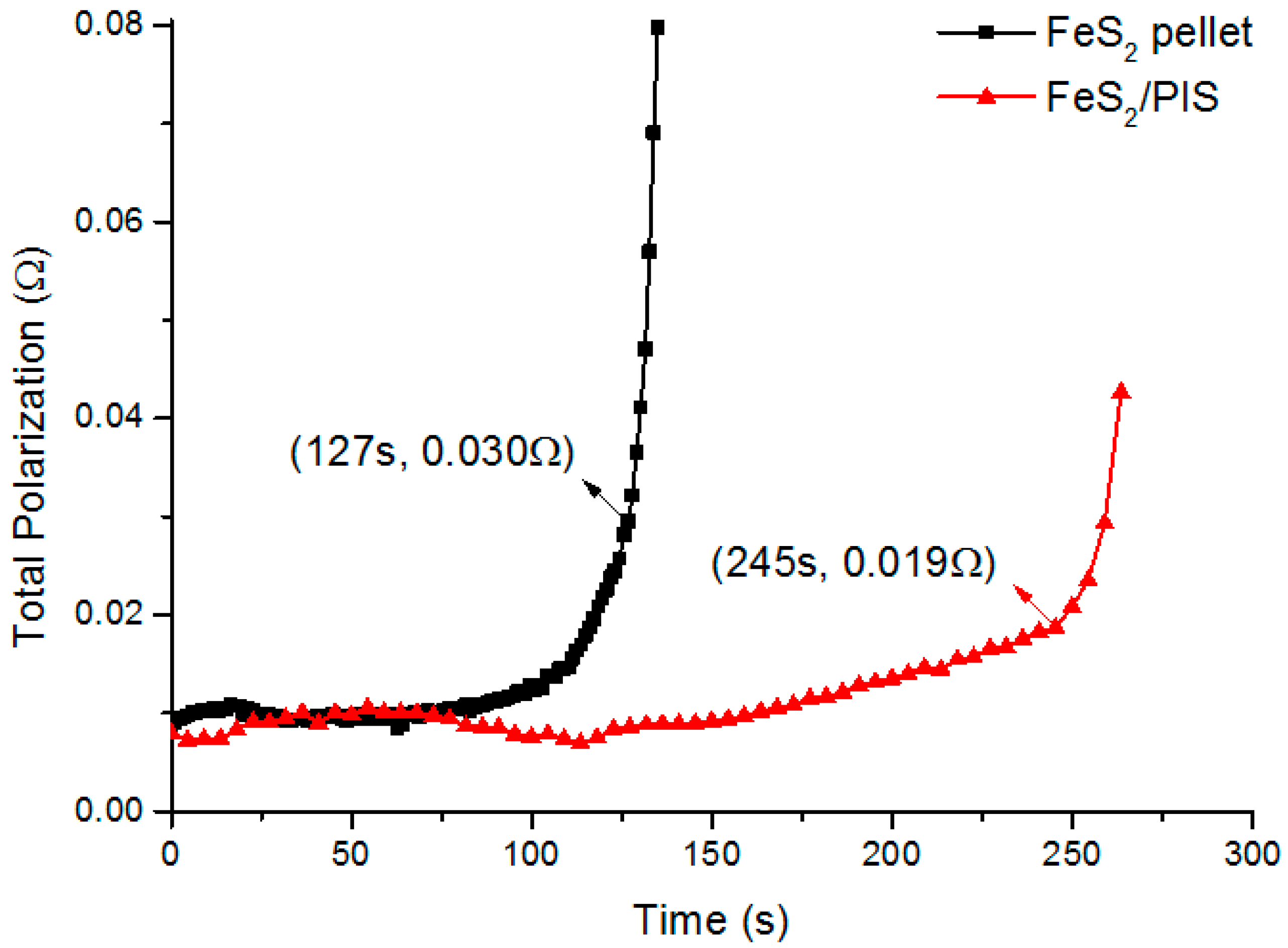
Based on the cell discharge test, the total polarization of the unit cell was calculated using the following Equation (1) reported by Fujiwara [24], and the results are shown in Figure 7.
Rt = (Voc − Vcc)/I
- Rt: total polarization (Ω)
- Voc: open circuit voltage (V)
- Vcc: close circuit voltage (V)
- I: discharge current (A)
Voc during discharging was the highest voltage when no current was applied for 0.5 s, and Vcc was the voltage when the voltage was lowest by applying the current for 4.5 s. As shown in Figure 7, the total polarization of the FeS2 (pellet) and FeS2/PIS thin layer cathodes showed a significant difference. In the initial discharge period, both electrodes showed a constant resistance of 0.01 Ω. However, the discharge time of FeS2/PIS electrode was twice as long as that of the FeS2, until the rapid rise of the resistance. Discharge times of 127 s and 245 s were shown at FeS2 (pellet) and FeS2/PIS at 1.3 V, which is the end of the typical discharge voltage in the thermal battery. At this time, the resistance of the FeS2 (pellet) electrode was in a state of rapid increase. On the other hand, in the FeS2/PIS electrode, 0.02 Ω was maintained up to 245 s before the rapid increase of resistance. The rapid increase in total polarization is known to occur when FeS2 reacts with Li ions to form Li3FeS4 (Z-phase) with low conductivity [25,26]. It can be said that the influence of the Z-phase generation is relatively low in the FeS2/PIS cathode. This is attributed to the structural characteristics of the electrode due to the thinning, and it can be interpreted that all the FeS2 particles are uniformly contacted, with the electrolyte and Z-phase generation occurring uniformly throughout the cathode layer, resulting in a delayed increase in resistance. Conversely, the increase in thickness causes a non-uniform Z-phase formation in the cathode layer, which rapidly increases the total polarization and eventually lowers the utilization of cathode materials. On the other hand, it is believed that the binding between FeS2 particles by the PIS binder residues was strengthened, and that the effect of increasing the connectivity also contributed. This is also related to the difference in the morphology change of the cathode material before and after the high temperature treatment (Figure 3).
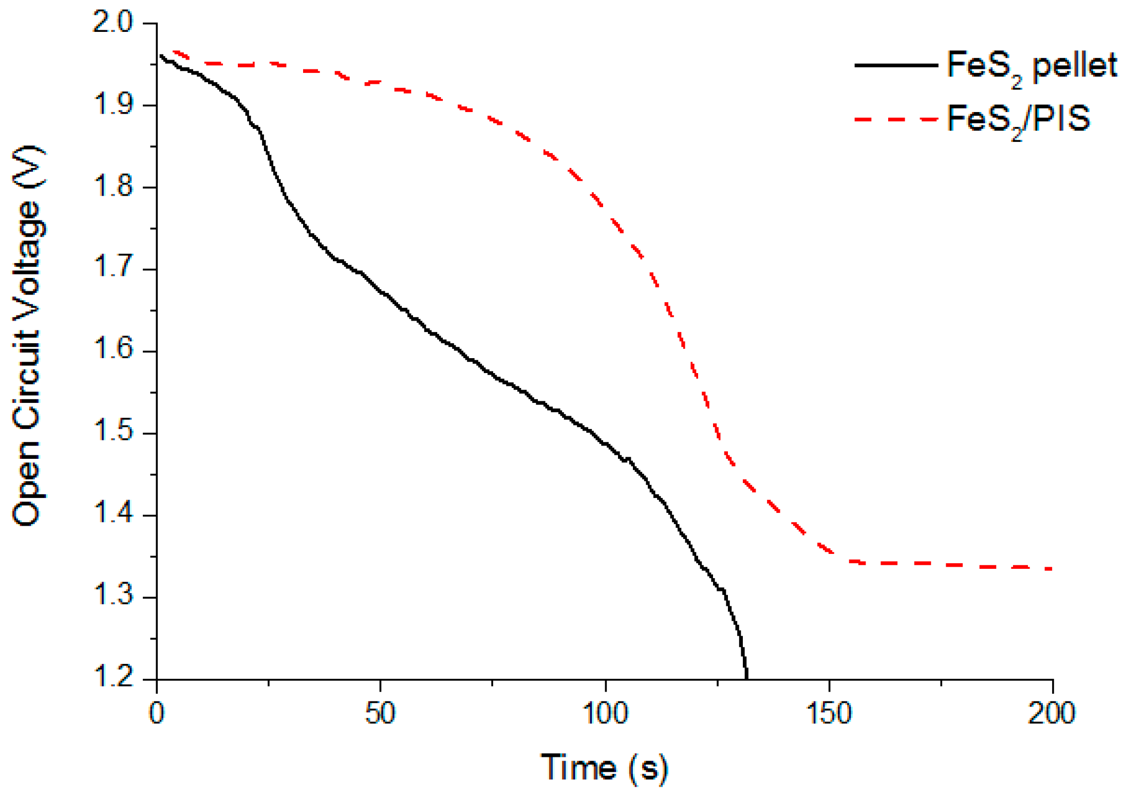
The change in open circuit voltage (OCV) is also different between the two cathodes (Figure 8). It is known that the 500 °C condition in the thermal battery leads to the thermal degradation of the cathode material, and it is accompanied by a decrease in OCV, due to self-discharge [27,28]. Both cathodes showed an initial OCV at 1.95 V. In the case of FeS2 (pellet), the OCV was continuously decreased as the discharge progressed, and it was considered to self-discharge due to relatively low thermal stability. The FeS2/PIS cathode maintained an initial 1.9 V level up to 70 s, and then it gradually decreased. The PIS binder exhibited a considerable advantage in terms of the stabilization of the OCV drop related to the thermal decomposition. This is consistent with the result that the surface of the FeS2 particles was retained in the cathode to which the PIS binder was applied, and that in the pure FeS2, the surface was deformed rapidly at a high temperature. This OCV retention property and the inhibition of the rapid increase of total polarization resulted in the increase of the discharge capacitance by more than 20% in the film cathode using PIS binder.
4. Conclusions
Poly(imide-co-siloxane) (PIS) was designed to exhibit heat-resistant properties and adhesion to FeS2 particles. This material was applied as the binder to produce a thin-film cathode composited with FeS2. The PIS binder showed a nano-scale coating of the FeS2 particles with a thickness of 10–20 nm. In addition, the PIS enabled the cathode composites to be thin-films, which were mechanically stable and could have thicknesses of 50–100 μm. The thickness of this layer was reduced to 20–10% of that of conventional pellet-type layers, providing significant bending and impact resistance. The FeS2/PIS composites were stable in the temperature range of 250–400 °C, and decomposition was observed at 450 °C, which is the operating temperature of the thermal battery. The thermal stability of FeS2/PIS composites was improved over pure FeS2. The binding of the FeS2 particles was retained at the operating temperature by the PIS residues. Through its role as a binder, the battery capacity was improved by 20% when compared to the pellet-type cathode by thin layer composite formation.
Supplementary Materials
The following are available online at https://www.mdpi.com/1996-1073/11/11/3154/s1, Figure S1: Structure and 1H-,13C-NMR analysis of polyimide, Figure S2: FT-IR analysis of poly(imide-co-siloxane), Figure S3: Bending test for cathode composite layer attached to the SUS plate and resulted in no cracks at 360° bending condition.
Author Contributions
Conceptualization, H.C.; Data curation, I.O., Y.S.Y. and H.M.J.; Formal analysis, J.C. and K.K.; Investigation, J.C., K.K. and J.K.; Project administration, H.C.; Writing—original draft, I.O. and H.M.J.; Writing—review & editing, Y.S.Y. and H.M.J.
Funding
This work was supported by the Gachon University research fund of 2017 (GCU-2017-0214). H.M.J. gratefully acknowledges support from National Research Foundation of Korea (NRF-2018R1D1A1B07050068).
Conflicts of Interest
The authors declare no conflict of interest.
References
- Kim, I.Y.; Shin, S.Y.; Ko, J.H.; Lee, K.S.; Woo, S.P.; Kim, D.K.; Yoon, Y.S. Functional Li-M (Ti, Al, Co, Ni, Mn, Fe)-O Energy Materials. J. Korean Ceram. Soc. 2017, 54, 9–22. [Google Scholar] [CrossRef] [Green Version]
- Lee, J.-Y.; Ngo, D.T.; Park, C.-J. Ge–Al Multilayer Thin Film as an Anode for Li-ion Batteries. J. Korean Ceram. Soc. 2017, 54, 249–256. [Google Scholar] [CrossRef]
- Guidotti, R.A.; Masset, P. Thermally activated (“thermal”) battery technology: Part I: An overview. J. Power Sources 2006, 161, 1443–1449. [Google Scholar] [CrossRef]
- Kim, D.; Jung, H.-M.; Um, S. Theoretical Analysis of the Time-Dependent Temperature Evolution for Thermal Runaway Prevention in Multi-Layered LiCl-LiBr-LiF Thermal Batteries. J. Korean Phys. Soc. 2009, 55, 2420–2426. [Google Scholar] [CrossRef]
- Guidotti, R.A.; Masset, P.J. Thermally activated (“thermal”) battery technology: Part IV. Anode materials. J. Power Sources 2008, 183, 388–398. [Google Scholar] [CrossRef]
- Masset, P.; Guidotti, R.A. Thermal activated (“thermal”) battery technology: Part II. Molten salt electrolytes. J. Power Sources 2007, 164, 397–414. [Google Scholar] [CrossRef]
- Masset, P.J.; Guidotti, R.A. Thermal activated (“thermal”) battery technology: Part IIIa: FeS2 cathode material. J. Power Sources 2008, 177, 595–609. [Google Scholar] [CrossRef]
- Masset, P.J.; Guidotti, R.A. Thermal activated (“thermal”) battery technology: Part IIIb. Sulfur and oxide-based cathode materials. J. Power Sources 2008, 178, 456–466. [Google Scholar] [CrossRef]
- Cho, K.-Y.; Riu, D.-H.; Huh, S.-H.; Shin, D.-G.; Kim, H.-E.; Cheong, H.-W.; Cho, S.-B. The Holding Characteristics of the Glass Filter Separators of Molten Salt Electrolyte for Thermal Batteries. J. Korean Ceram. Soc. 2008, 45, 464–471. [Google Scholar] [CrossRef]
- Ko, J.; Kim, I.Y.; Cheong, H.; Yoon, Y.S. Organic binder-free cathode using FeS2-MWCNTs composite for thermal batteries. J. Am. Ceram. Soc. 2017, 100, 4435–4441. [Google Scholar] [CrossRef]
- Ko, J.; Kim, I.Y.; Jung, H.M.; Cheong, H.; Yoon, Y.S. Thin cathode for thermal batteries using a tape-casting process. Ceram. Int. 2017, 43, 5789–5793. [Google Scholar] [CrossRef]
- Zhang, T.; Li, J.T.; Liu, J.; Deng, Y.P.; Wu, Z.G.; Yin, Z.W.; Guo, D.; Huang, L.; Sun, S.G. Suppressing the voltage-fading of layered lithium-rich cathode materials via an aqueous binder for Li-ion batteries. Chem. Commun. 2016, 52, 4683–4686. [Google Scholar] [CrossRef] [PubMed]
- Zhang, S.; Gu, H.; Pan, H.; Yang, S.; Du, W.; Li, X.; Gao, M.; Liu, Y.; Zhu, M.; Ouyang, L.; et al. A Novel Strategy to Suppress Capacity and Voltage Fading of Li- and Mn-Rich Layered Oxide Cathode Material for Lithium-Ion Batteries. Adv. Energy. Mater. 2017, 7, 1601066. [Google Scholar] [CrossRef]
- Kong, J.-Z.; Xu, L.-P.; Wang, C.-L.; Jiang, Y.-X.; Cao, Y.-Q.; Zhou, F. Facile coating of conductive poly(vinylidene fluoride-trifluoroethylene) copolymer on Li1.2Mn0.54Ni0.13Co0.13O2 as a high electrochemical performance cathode for Li-ion battery. J. Alloys Compd. 2017, 719, 401–410. [Google Scholar] [CrossRef]
- Xu, J.; Chou, S.-L.; Gu, Q.; Liu, H.-K.; Dou, S.-X. The effect of different binders on electrochemical properties of LiNi1/3Mn1/3Co1/3O2 cathode material in lithium ion batteries. J. Power Sources 2013, 225, 172–178. [Google Scholar] [CrossRef]
- Morishita, M.; Yamano, A.; Kitaoka, T.; Sakai, H.; Ojima, T.; Sakai, T. Polyamide-Imide Binder with Higher Adhesive Property and Thermal Stability as Positive Electrode of 4V-Class Lithium-Ion Batteries. J. Electrochem. Soc. 2014, 161, A955–A960. [Google Scholar] [CrossRef]
- Wu, F.; Li, W.; Chen, L.; Lu, Y.; Su, Y.; Bao, W.; Wang, J.; Chen, S.; Bao, L. Polyacrylonitrile-polyvinylidene fluoride as high-performance composite binder for layered Li-rich oxides. J. Power Sources 2017, 359, 226–233. [Google Scholar] [CrossRef]
- Pieczonka, N.P.W.; Borgel, V.; Ziv, B.; Leifer, N.; Dargel, V.; Aurbach, D.; Kim, J.H.; Liu, Z.; Huang, X.; Krachkovskiy, S.A.; et al. Lithium Polyacrylate (LiPAA) as an Advanced Binder and a Passivating Agent for High-Voltage Li-Ion Batteries. Adv. Energy Mater. 2015, 5, 1501008. [Google Scholar] [CrossRef]
- Lee, Y.M.; Choi, J.; Ryou, M.H.; Son, B.; Song, J.; Park, J.K.; Cho, K.Y. Improved high-temperature performance of lithium-ion batteries through use of a thermally stable co-polyimide-based cathode binder. J. Power Sources 2014, 252, 138–143. [Google Scholar] [CrossRef]
- Cho, J.-H.; Park, J.-H.; Lee, M.-H.; Song, H.-K.; Lee, S.-Y. A polymer electrolyte-skinned active material strategy toward high-voltage lithium ion batteries: A polyimide-coated LiNi0.5Mn1.5O4 spinel cathode material case. Energy Environ. Sci. 2012, 5, 7124–7131. [Google Scholar] [CrossRef]
- Park, J.-H.; Cho, J.-H.; Kim, S.-B.; Kim, W.-S.; Lee, S.-Y.; Lee, S.-Y. A novel ion-conductive protection skin based on polyimide gel polymer electrolyte: Application to nanoscale coating layer of high voltage LiNi1/3Co1/3Mn1/3O2 cathode materials for lithium-ion batteries. J. Mater. Chem. 2012, 22, 12574–12581. [Google Scholar] [CrossRef]
- Qian, G.; Wang, L.; Shang, Y.; He, X.; Tang, S.; Liu, M.; Li, T.; Zhang, G.; Wang, J. Polyimide Binder: A Facile Way to Improve Safety of Lithium Ion Batteries. Electrochim. Acta 2016, 187, 113–118. [Google Scholar] [CrossRef]
- Pham, H.Q.; Kim, G.; Jung, H.M.; Song, S.-W. Fluorinated Polyimide as a Novel High-Voltage Binder for High-Capacity Cathode of Lithium Ion Batteries. Adv. Funct. Mater. 2017, 28, 1704690. [Google Scholar] [CrossRef]
- Fujiwara, S.; Inaba, M.; Tasaka, A. New molten salt systems for high-temperature molten salt batteries: LiF–LiCl–LiBr-based quaternary systems. J. Power Sources 2010, 195, 7691–7700. [Google Scholar] [CrossRef]
- Zhang, D.; Mai, Y.J.; Xiang, J.Y.; Xia, X.H.; Qiao, Y.Q.; Tu, J.P. FeS2/C composite as an anode for lithium ion batteries with enhanced reversible capacity. J. Power Sources 2012, 217, 229–235. [Google Scholar] [CrossRef]
- Choi, Y.; Yu, H.; Cheong, H.R.; Cho, S.; Lee, Y.S. Effects of Pyrite (FeS2) Particle Sizes on Electrochemical Characteristics of Thermal Batteries. Appl. Chem. Eng. 2014, 25, 161–166. [Google Scholar] [CrossRef]
- Schoeffert, S. Thermal batteries modeling, self-discharge, and self-heating. J. Power Sources 2005, 142, 361–369. [Google Scholar] [CrossRef]
- Masset, P.; Schoeffert, S.; Poinso, J.Y.; Poignet, J.C. LiF-LiCl-LiI vs. LiF-LiBr-KBr as molten salt electrolyte in thermal batteries. J. Electrochem. Soc. 2005, 152, A405–A410. [Google Scholar] [CrossRef]
Figure 1.
Schematic view of a thermal battery and the FeS2/ poly(imide-co-siloxane) (PIS) composite cathode.
Figure 1.
Schematic view of a thermal battery and the FeS2/ poly(imide-co-siloxane) (PIS) composite cathode.

Scheme 1.
Preparation of the polyimide and the formation of the cross-linked poly(imide-co-siloxane). (a) Preparation for polyimide; (b) Cross linking step with polyaminosiloxane.
Scheme 1.
Preparation of the polyimide and the formation of the cross-linked poly(imide-co-siloxane). (a) Preparation for polyimide; (b) Cross linking step with polyaminosiloxane.

Figure 2.
Thermogravimetric analysis (TGA) thermogram of the PIS and FeS2/PIS composites.

Figure 3.
Scanning electron microscope (SEM) and transmission electron microscope (TEM) images of the cathode layer composites of FeS2/PIS: (a,c) after formation of the cathode composites at 250 °C; (b,d) after a 1 h treatment at 450 °C. SEM images of pellet-type FeS2: (e) after formation of the cathode; (f) after a 1 h treatment at 450 °C.

Figure 4.
X-ray photoelectron spectroscopy (XPS) analysis for the cathode layer of the FeS2/PIS: (a) after the formation of the cathode composites at 250 °C; (b) after a 1 h treatment at 450 °C.
Figure 4.
X-ray photoelectron spectroscopy (XPS) analysis for the cathode layer of the FeS2/PIS: (a) after the formation of the cathode composites at 250 °C; (b) after a 1 h treatment at 450 °C.

Figure 5.
Current-voltage characteristics of the FeS2/PIS thin film.

Figure 6.
Discharge capacities of the FeS2/PIS thin layer cathode and the pellet-type FeS2.

Figure 7.
Total polarization for the FeS2/PIS thin layer cathode and the pellet-type FeS2.

Figure 8.
Open circuit voltage changes for the FeS2/PIS thin layer cathode and pellet-type FeS2.

© 2018 by the authors. Licensee MDPI, Basel, Switzerland. This article is an open access article distributed under the terms and conditions of the Creative Commons Attribution (CC BY) license (http://creativecommons.org/licenses/by/4.0/).
Share and Cite
MDPI and ACS Style
Oh, I.; Cho, J.; Kim, K.; Ko, J.; Cheong, H.; Yoon, Y.S.; Jung, H.M. Poly(imide-co-siloxane) as a Thermo-Stable Binder for a Thin Layer Cathode of Thermal Batteries. Energies 2018, 11, 3154. https://doi.org/10.3390/en11113154
AMA Style
Oh I, Cho J, Kim K, Ko J, Cheong H, Yoon YS, Jung HM. Poly(imide-co-siloxane) as a Thermo-Stable Binder for a Thin Layer Cathode of Thermal Batteries. Energies. 2018; 11(11):3154. https://doi.org/10.3390/en11113154
Chicago/Turabian StyleOh, Ilwhan, Jaeyoung Cho, Kwansu Kim, Jaehwan Ko, Haewon Cheong, Young Soo Yoon, and Hyun Min Jung. 2018. "Poly(imide-co-siloxane) as a Thermo-Stable Binder for a Thin Layer Cathode of Thermal Batteries" Energies 11, no. 11: 3154. https://doi.org/10.3390/en11113154
Note that from the first issue of 2016, this journal uses article numbers instead of page numbers. See further details here.