Location Planning for Dynamic Wireless Charging Systems for Electric Airport Passenger Buses


1
Department of Production Management, Leibniz Universitat Hannover, 30167 Hannover, Germany
2
Department of Industrial and Systems Engineering, Korea Advanced Institute of Science and Technology, 305-701 Daejeoen, Korea
3
Institute of Flight Guidance, Technische Universitat Braunschweig, 38118 Braunschweig, Germany
*
Author to whom correspondence should be addressed.
Energies 2018, 11(2), 258; https://doi.org/10.3390/en11020258
Submission received: 13 December 2017
/
Revised: 12 January 2018
/
Accepted: 18 January 2018
/
Published: 23 January 2018
(This article belongs to the Special Issue Towards a Transformation to Sustainable Aviation Systems)
Abstract
:The majority of the ground vehicles operating on the airside parts of commercial airports are currently powered by diesel engines. These include vehicles such as apron buses, fuel trucks, and aircraft tractors. Hence, these vehicles contribute to the overall CO emissions of the aviation transport system and thus negatively influence its environmental footprint. To reduce this damaging environmental impact, these vehicles could potentially be electrified with on-board batteries as their energy sources. However, the conductive charging of such vehicles via stationary cable connections is rather time-consuming. A dynamic wireless charging system to supply public transportation passenger buses with electric energy while in motion has recently been installed on the Korea Advanced Institute of Science and Technology (KAIST) campus and in the Korean city of Gumi. In this paper, we study configuration problems related to the use of this technology to make airport operations more environmentally sustainable. We concentrate on the power supply for apron buses and analyze the location planning problems related to the distribution of the required power supply and the wireless charging units in the apron road system. To this end, we develop a formal optimization model and discuss the first numerical results.
1. Introduction
Several types of ground vehicles operate on the airside parts of today’s commercial airports, particularly on the apron. These include passenger-carrying apron buses, baggage and aircraft tractors, fuel trucks, and several others. Very often, these vehicles are powered by diesel engines and hence contribute to the overall CO emissions caused by or related to the aviation transport system. To reduce CO emissions, many airports are in the process of electrifying these vehicles, with on-board batteries as their energy sources. This is in line with Flightpath 2050, Europe’s vision for sustainable future aviation systems [1]. The current standard procedure is to charge these batteries conductively via a cable connection while they are not operating. In addition to requiring specific charging spaces, this approach reduces the vehicles’ availability [2] since the charging times tend to be substantial compared with the fueling of vehicles with conventional internal combustion engines.
In this paper, we focus on a particular dynamic wireless charging technology for supplying electric energy to such vehicles while they are operating. Due to the particular nature of the service requests for the types of vehicles operating on the airside part of an airport, this wireless charging technology might be especially attractive for apron ground operations. However, wireless power transfer technology requires a substantial investment in power supply units (PSUs), including a power inverter to provide an alternating current with the required frequency and inductive transmitter units (ITUs) that would have to be placed below the surface of the service road [3] on the airside part of the airport.
Therefore, we study the location problems related to the potential usage of this innovative technology. With the ultimate objective of conducting a comprehensive analysis concerning the electrification of all apron ground traffic, we start by considering only a specific type of vehicle, namely, the apron bus.
This paper is structured as follows: in Section 2, we briefly describe important aspects of apron ground traffic at commercial airports and key aspects of dynamic wireless charging technology. On this basis, we specify our assumptions about the location problems that arise with the implementation of dynamic wireless charging technology for passenger-carrying apron buses at commercial airports and discuss the related literature. An optimization model that precisely characterizes a potential mathematical interpretation of the problem is presented in Section 3. In Section 4, we study a fictitious example of a small airport to explore important structural properties of optimal designs for the charging infrastructure. We comment on aspects of the solution and provide directions for future research in Section 5.
2. Characterization of the Problem
2.1. Apron Bus Traffic on the Airside Part of a Commercial Airport
Much of the airside traffic at a commercial airport involving ground vehicles such as apron buses, baggage cart tractors, aircraft tractors, fuel trucks, and cleaning vehicles is related to the aircraft turnaround process while an aircraft is either parked next to an airport terminal and thus connected to the terminal building via a passenger boarding bridge or parked at an apron parking position some distance from the terminal building(s). Figure 1 shows both types of aircraft parking positions for the example of Stuttgart Airport, Germany.
Stuttgart Airport is a medium-sized international airport with a single runway. It connects Stuttgart to numerous European destinations, including the major hubs for long-distance flights, as well as some destinations outside of Europe. Traffic at this airport exceeds the capacity available to serve all aircraft at terminal positions during their turnaround processes. Some of these terminal positions are shown in the upper part of Figure 1. As a result, aircraft are often parked at some of the airport’s 38 apron parking positions, some of which are shown in the lower part of Figure 1.
Several similar parking positions are located in different parts of the apron. A stylized abstraction of these groups of parking positions and the terminal buildings is shown in Figure 2. In this graph, nodes T1 to T3 represent terminals, whereas nodes C to J represent groups of apron parking positions that are not directly connected to a terminal and hence require passenger transport by apron buses.
A more detailed description of the apron road system for ground vehicles in the vicinity of Terminal 3 is presented in Figure 3. In front of the terminal building, a two-lane road (one lane for each direction) is designated to be used by passenger-carrying apron buses and other types of vehicles. To pick up passengers at one of Terminal 3’s departure gates, to , such a bus pulls backward into the bus parking position (denoted by Bus Parking Position (BPP) in Figure 3) in front of the corresponding gate, e.g., using the connection between nodes and in Figure 3. Likewise, passengers arriving in Stuttgart on an aircraft that is parked at an apron position can disembark from an apron bus at arrival gate or of Terminal 3.
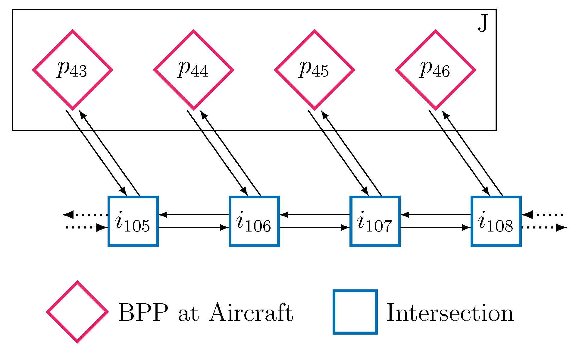
Similarly, the apron parking positions for the aircraft and the roads for service vehicles required for the turnaround process are also painted on the apron, as shown schematically in Figure 4.
Many service requests for passenger-carrying apron buses originate at one of the parking positions next to a terminal building and require an initial trip to one of the aircraft parking positions on the apron followed by a second trip back to one of the terminal gates. Passengers are either brought from a departure gate to their corresponding parked aircraft or from the aircraft to an arrival gate. To simplify the analysis, we neglect empty trips between terminal gates and between aircraft parking positions.
Depending on the current status of airport operations, apron buses are flexibly dispatched to serve passenger transportation requests while essentially following the two-trip structure described above. Due to the large number of terminal gates and aircraft parking positions, a very large number of different requests may arise. However, the routing for each request will typically be known a priori, e.g., the route with the minimal driving distance. Note that, due to the two-trip structure, it is conceivable that a particular road segment may need to be used twice to serve a single request if the road network contains one-way roads and loops.
Compared with the operation of passenger buses for public transportation in urban or rural areas, the operation of apron buses exhibits several unique features. One is that the time for which a bus is stopped at either the terminal or the apron parking position is relatively long because all passengers will always either board or de-board the bus. In addition, if the passengers are boarding the bus during such a stop, they often do so relatively slowly because they must either pass through a boarding pass checking process at the terminal gate or exit the aircraft one by one via mobile passenger boarding stairs. As a result, relative to the energy required to actually move the bus, a large proportion of the energy consumed by an apron bus is used for systems such as air conditioning, heating, illumination, and communication. Weather conditions may have a major impact on the energy required to serve passenger transportation requests, particularly under extreme weather conditions. All of these factors must be considered when designing a wireless charging infrastructure for apron buses.
In this paper, we focus on the electrification of the apron buses for passengers in combination with the implementation of wireless charging technology. It is conceivable that this technology may also be used for other vehicles operating on the apron. One might even consider the electrification of the aircraft tractors. This might become especially appealing if those tractors were to be used to pull aircraft along taxiways to reduce the consumption of energy internally stored in the aircraft as suggested in the Flightpath 2050 report [1] (p. 15).
2.2. Dynamic Wireless Inductive Charging of Electric Vehicles
A dynamic wireless charging system is a new type of electric vehicle charging system in which the battery in a vehicle is remotely charged by a power transmitter embedded in the road. The technology is innovative because it allows charging to be performed while the vehicle is in motion [4]. This technology is based on wireless power transfer (WPT). Two coils placed close to each other exhibit mutual inductive coupling when they are configured such that a time-varying current flowing through one wire induces a voltage across the ends of the other wire through electromagnetic induction [5,6]. WPT has been successfully applied to charge various handheld devices, such as electronic toothbrushes, phones, and medical devices. It has also been widely used for automated material handling systems in semiconductor fabrication and liquid crystal display (LCD) production lines [7].
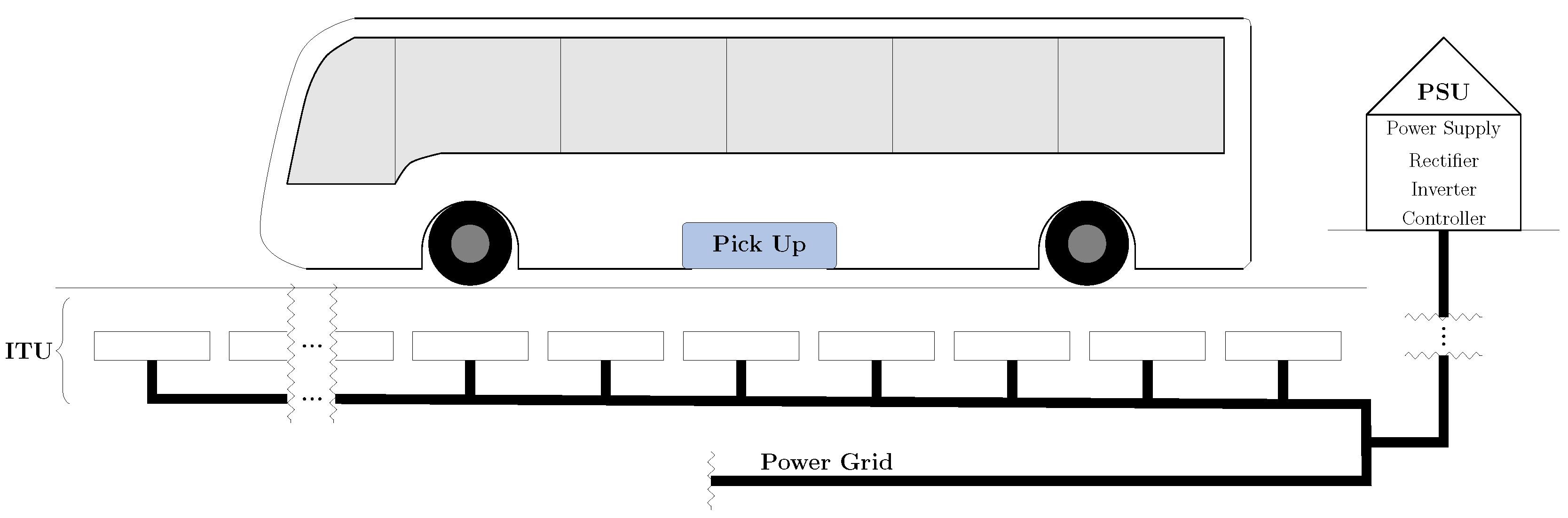
A typical dynamic charging system consists of a vehicle unit and a power transmitter unit (PTU), as shown in Figure 5. The PTU is essentially composed of a power inverter and an inductive cable. The power inverter is the main component of the power supply unit (PSU), which also hosts a controller. It creates an alternating current with a frequency on the order of magnitude of 20 to 85 kHz and supplies power to the connected inductive cable. This inductive cable is the main component of the inductive transmitter unit (ITU). It is usually installed beneath the road in an elongated configuration along the direction of travel of a lane.
As shown in Figure 6, the ITU generates a precisely shaped local electromagnetic field. The pickup system attached to the bottom surface of the vehicle receives power from the PTU. When the vehicle passes over a road segment equipped with an ITU, it picks up electrical energy from the ITU, and the battery is charged while the vehicle is in motion (or standing). When the vehicle is moving in an area with no power transmitters, it consumes the energy stored in the battery [8].
Dynamic wireless charging has multiple benefits. It significantly reduces charging downtime [2], namely, the idle time during which an electric vehicle is not operational while the battery is charging. It also eliminates the need for a large battery. Furthermore, frequent dynamic wireless charging positively influences the life cycle of a battery. A recent study by [9] indicates that, as shown in Figure 7, frequent shallow charging via dynamic wireless charging is less stressful to a lithium-based battery (currently, the most widely used battery type) than the infrequent deep charging that is typical of conventional conductive charging. The Korea Advanced Institute of Science and Technology (KAIST) first commercialized a dynamic charging electric vehicle system called the On-Line Electric Vehicle (OLEV) system. The key technology underlying OLEV is a shaped magnetic field in resonance (SMFIR), which effectively magnifies electric waves, so that charging efficiencies of up to 80% have been achieved [5,10,11]. The first commercially implemented version of OLEV is the trolley in Seoul Grand Park, one of the largest theme parks in South Korea [12]. The trolley serves a 2.2 km circular route around the theme park, with four PTUs.
The shuttle buses on the KAIST campus constitute the second commercial implementation [4]. Two OLEV-based shuttle buses have been in service since 2012. The first commercial OLEV system deployed in a normal traffic environment is the one in Gumi City, one of the largest industrial cities in South Korea, where two OLEV-based buses have been serving a 35 km route since 2013. There are also a few other commercialized OLEV systems. The research and development history of SMFIR technology is described in the recent book by Suh and Cho [5]. Another example of the use of inductive charging of electric buses for urban public transportation is a project [3] in the city of Braunschweig, Germany, where buses are charged wirelessly while they are standing either at a re-charging station or at a bus stop but not while they are in motion. A similar application in the city of Milton Keynes, United Kingdom has also been reported [13].
2.3. Placement of the Wireless Charging Infrastructure on the Airport Apron
Given the specific characteristics of the apron bus traffic on the airside part of a commercial airport as described in Section 2.1 and of the dynamic wireless charging technology introduced in Section 2.2, we are now in a position to define an important problem related to the use of this wireless power transfer technology for passenger-carrying apron buses.
For successful operation with this technology, a sufficiently large part of the airside road network must be equipped with wireless charging systems as a bus can only pick up energy wirelessly while it is standing or moving above an ITU. Each such system consists of a PSU (including the power inverter delivering an alternating current with the required frequency) on the one hand and an ITU on the other hand. The spatial allocation of these components must be such that each road segment equipped with an ITU is connected to its PSU either directly or indirectly via some other road segment equipped with an ITU that itself is connected to the PSU.
We assume that the locations of the PSUs and ITUs must be such that an apron bus serving any conceivable passenger transportation request can receive at least the amount of energy that is required to serve this request while traveling on the road segments that are required for this particular request.
The advantage of formulating the problem in this way is that we do not need to model the dynamics of the state of charge (SOC) of the vehicle’s battery. Although the SOC of the bus will vary while the vehicle serves a particular request, we can be sure that the battery will always receive sufficient energy during operation such that it will never need to cease operating for conductive battery recharging. As a result, we can also treat each particular request type in isolation, both in the design phase addressed in this paper and during the actual operation of the system. It is necessary neither to consider the total energy demand and supply over several coordinated requests nor to temporarily send the vehicle to a specific charging station between any two service requests.
Furthermore, we assume that only a prespecified subset of road segments can be equipped with the underground inductive infrastructure. For example, it may be that some parts of the roads used by the apron buses have a standard asphalt surface and can be equipped with ITU cables at a relatively low cost, whereas other road segments are merely painted on the concrete apron surface. For these latter road segments, it may be more expensive, difficult or potentially even impossible to install the charging infrastructure at all. Likewise, it is conceivable that only select candidate positions for the power inverters may exist.
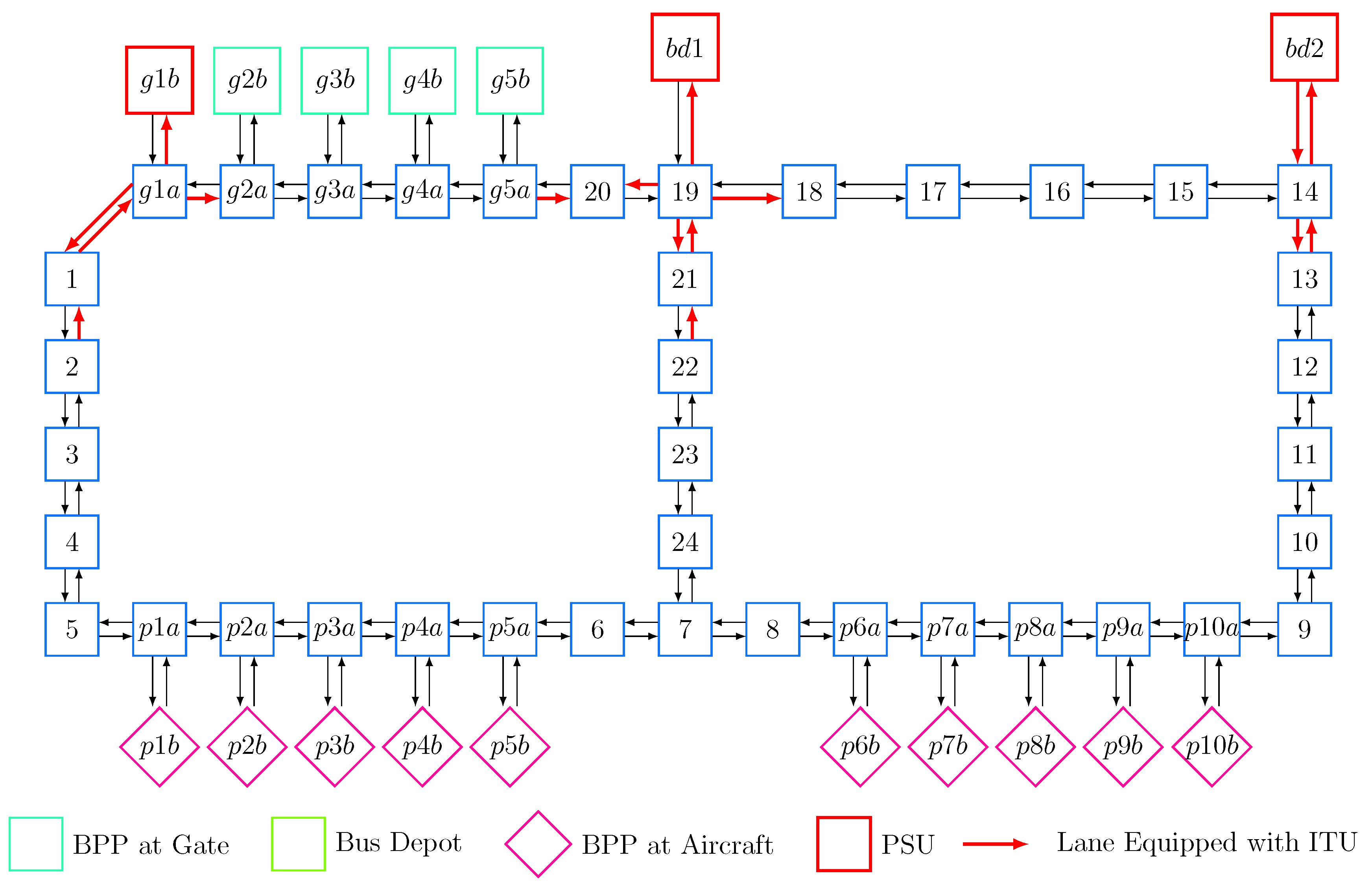
We assume that the lane segments of the roads can be represented by arcs in directed graphs. Figure 8 shows a configuration for a part of a road system with a PSU assigned to node 6 in such a directed graph. The lane segments to be equipped with underground ITUs are depicted as solid red arrows, indicating the driving direction, whereas non-solid black arrows represent lane segments not equipped with an ITU. In this installation configuration, the ITU from node 7 to node 6 also indirectly connects the lane segments from node 7 to node 3 and from 7 to 8 to the PSU at node 6, regardless of the driving directions of the corresponding lanes.
Note that, in this paper, we do not consider the power dimensioning problem related to the selected PSUs. This is also a rich problem setting and one that requires forecasting of the maximum traffic volume. We assume that this problem is solved in a subsequent planning stage once the location problem studied in this paper has been solved.
With respect to the planning objective, we assume that we seek an allocation that requires a certain minimum investment in PSUs and ITUs. Since PSUs are relatively costly but can supply ITUs for road segments of variable lengths, the cost structure of the problem exhibits a fixed-cost component similar to that of a dynamic lot-sizing problem, as described in [14].
Note that in this paper, we do not consider potential problems of electromagnetic (in-)compatibility between the wireless charging system on the one hand and the aircraft equipment and operations on the other.
2.4. Related Literature
We are not aware of any literature addressing the problem of the inductive charging of electric apron buses for airport passengers that is treated in this paper. However, the charging-in-motion capability of dynamic wireless charging has led to several publications addressing operational issues. One important aspect is that the amount of charging energy depends on the amount of time a vehicle spends traveling over a power transmitter. That is, if a vehicle drives slowly over a power transmitter, it can absorb more electrical energy from the power transmitter than if it drives over it quickly. Therefore, the amount of charging energy is coupled with the velocity of the vehicle [15]. As a result, the vehicle velocity needs to be considered when determining the allocation of the ITUs and connected PSUs. Moreover, there is a trade-off between the power transmitter allocation and the size of the vehicle’s battery. A smaller battery might be sufficient if power transmitters are installed in more places. Therefore, the allocation of the power transmitters needs to be considered along with the size of the battery. Ko and Jang [15] first proposed a mathematical optimization model for determining the economical allocation of power transmitters while considering battery size. They formalized the optimization model by validating their various assumptions and approximation approaches on the basis of OLEV-based trolleys operating on a single travel route in Seoul Grand Park, the first commercialized dynamic charging system. The recent work done by [16] extends this model to multiple routes. Liu and Song [17] also considered the multiple-route case for the power transmitter allocation problem. They incorporated charging and discharging uncertainties into the model using a robust optimization approach.
Another aspect of research on dynamic wireless charging is cost–benefit analysis. Jang et al. [18] proposed a method of estimating the initial investment cost for dynamic wireless charging. Their study analyzed the cost structure of dynamic wireless charging and identified the conditions and scenarios under which dynamic wireless charging is cost-competitive. Bi et al. [19] and Bi et al. [20] investigated the associated life-cycle energy cost and greenhouse gas consumption for a dynamic charging system. The life-cycle cost model provided a holistic evaluation of the costs from capital investment to use-phase operations to the end of the life cycle. Although these studies have provided a general model approach, algorithms, and cost-benefit analyses, no study has specifically considered the characteristics and properties of airport passenger bus traffic.
The operational literature on the airside infrastructures of commercial airports mainly focuses on the efficient utilization of the available capacities. Fernandes and Pacheco [21] performed a data envelopment analysis of various airports to analyze efficiency levels. Based on passenger demand forecasts, they also researched the capacity expansions required to ensure a certain service level. Stamatopoulos et al. [22] introduced a decision support tool for strategic planning for airports that considers various runway systems and airfield aprons. They concentrated on the estimation of airfield capacities and related delays in a dynamically changing airport framework. By applying their approach to a real-world setting, they verified their approximations concerning the observed delays. Zhang et al. [23] investigated the impact of airside efficiency improvements with respect to capacity expansions. They especially focused on the take-off and landing distances of runways. Their results show that airports with two runways tend to be subject to decreasing returns to scale, whereas airports with one runway experience increasing returns to scale. Mirkovic and Tosic [24] concentrated on the capacity utilization and development of airport aprons rather than on runway or facility expansion; to this end, they discussed various modeling approaches for apron capacity development.
Research on ground service vehicle management with respect to airport aprons has given rise to various optimization approaches. Kuhn and Loth [25] focused on algorithms for scheduling ground service vehicles and introduced a mixed-integer programming formulation to minimize both fuel costs and air carrier delays. By applying their approach, Kuhn and Loth [25] achieved a 20% reduction in aircraft delays and the distance traveled by service vehicles. Andreatta et al. [26] proposed a mathematical formulation and a sequential heuristic for optimizing the assignment of vehicles to apron ground service operations. They incorporated various factors that can disrupt the operation of ground services, such as aircraft delays. The results showed an average reduction of 7.5% in the distance traveled by service vehicles.
3. Optimization Model for Determining the Spatial Distribution of the Charging Infrastructure
In our model, we make the following assumptions to formalize the problem outlined in Section 2.3, using the notation presented in Table 1:
- The road system used by the apron buses and other airside airport service vehicles is modeled as a graph consisting of a set of nodes or vertices and a set of directed links , where and each link represents a road segment leading from node i to node j.
- A subset of the nodes are technologically feasible candidates to be equipped with PSUs (including the power inverters), which would require a capital investment of for each .
- A subset of the links can be equipped with ITUs. If a link l is equipped with an ITU, the ITU must extend for the entire length of the link. The required capital investment is . An apron bus traversing this link l can receive an energy intake of energy units during the time it spends either standing or moving on this link.
- Each link that is actually equipped with an ITU must be connected to a PSU.
- For each candidate node to be potentially equipped with a PSU, the set of candidate nodes that could then be connected to this PSU at node k is denoted by . The set of all nodes that could potentially be connected to any PSU is denoted by ; i.e., .
- For node to be connected to a PSU at node k, one of its immediate predecessors along a connection from node k to node j must also be connected to node k. To this end, a link from node i to node j and/or vice versa must be equipped with an ITU. For example, in Figure 8, node 3 can be connected to the PSU at node 6 via nodes 3 and 7 and the links (2, 3), (7, 3), and (7, 6).
- A passenger service request for the apron buses results in an energy consumption . This consumption is calculated based on the (standard) routing for this request. The standard routing and the corresponding energy consumption for each possible request are assumed to be determined in a pre-processing step. The set denotes the set of links that are used for request r and can potentially be equipped with ITUs. The parameter indicates how many times a link is used while serving a request .
- The allocation of ITUs to links must be such that for each possible request r, the bus can regain at least the amount of energy required to serve this particular request while using the corresponding set of predetermined links for this request.
It should be noted that the number of possible requests can be very large due to the large number of possible combinations of a terminal origin gate, an apron aircraft parking position, and a terminal destination gate that originate from the assumed two-trip structure of the service requests for apron buses. Based on the assumptions stated above and using the notation in Table 1, we can express the optimization problem as follows:
Wireless Charging Model:
subject to
The objective function (1) of the model minimizes the total capital requirement for the PSUs and the ITUs below the surfaces of the apron roads. Constraint (2) requires that, for each potential request r, the possible energy intake while serving the request must be at least equal to the request’s energy consumption. Note that it is conceivable that a particular link equipped with an ITU may be traversed multiple times while serving a single request r.
According to constraint (3), for each link l that is powered by a PSU at node k, both the origin and destination nodes of that link must also be connected to the same node k. Constraint (4) states that if node j is connected to a PSU at node k, then at least one of node j’s immediate predecessors along a closed connection from node k to node j must also be powered by node k. An example of such a closed connection is the connection between nodes 6 and 9 in Figure 8 via links (7, 6), (7, 8), and (9, 8), which are equipped with ITUs. According to constraint (6), every pair of nodes i and j along a given connection must be connected by at least one ITU. Constraint (5) enforces the installation of the PSUs.
Each link that can be equipped with an ITU can be connected to at most one node with a PSU, as enforced by constraint (7). Likewise, constraint (8) imposes the same principle for nodes. According to constraints (9)–(11), the allocations of ITUs and PSUs and the connections of nodes to the PSUs are restricted to the corresponding candidate sets , , and , respectively.
4. Numerical Study and Results
To study the structural properties of solutions to the problem described in Section 2 and formally modeled in Section 3, we implemented the model using the General Algebraic Modeling System (GAMS) and the CPLEX solver for the small apron road network depicted in Figure 9. We assume that, in this network, passengers board or de-board the buses at five gate positions, denoted by to . Buses can be parked at two bus depots, and . Due to the assumed two-trip structure of the service requests as stated in Section 2, a service request starts at one of seven possible origin nodes (five gates and two bus depots) includes one of 10 possible aircraft parking positions, and ends again at one of the seven nodes at the terminal or the bus depots, hence resulting in possible distinct requests. For each of these requests, we determined the shortest route and corresponding energy consumption value for a fictitious electric apron bus as a pre-processing step.
Information about the set of nodes that can serve as starting or ending nodes of links that can be potentially equipped with ITUs is given in Table 2. We assume that PSUs can be located next to nodes , , , and . From each of these locations, any link between the nodes in the set can be connected to and powered by the installed PSUs. In the example, we therefore assume that those parts of the apron road network that are relatively close to terminal buildings and not in the center of the apron are natural candidates for the placement of the charging infrastructure for the apron buses. We do not report the numerous other technical parameter values about distances, shortest-path routes, bus velocities, durations of bus (de-)boarding operations, respective power demands and supplies, assumed cost figures, etc., as the case is fictitious and only the ratios of these values are relevant for the structure of the solutions presented below.
For this fictitious example, we consider two opposing cases: in Case A, we assume that a PSU is relatively inexpensive compared with the investment in the ITUs. For this case, the resulting structure is depicted in Figure 10. Here, three PSUs are installed, at nodes , , and . Each of these PSUs serves to power a relatively small set of links in the immediate neighborhood of the corresponding node.
The optimal solution for the opposite Case B, with relatively expensive PSUs, is shown in Figure 11. In this situation, only a single PSU is installed at node , which represents the first passenger gate. From there, a single connected structure of links equipped with ITUs is powered.
A further analysis shows that, in Case A, four out of 12 connections between adjacent nodes i and j are established with ITUs in both directions, from i to j as well as from j to i. In Case B, however, such bi-directional allocations are established for only three out of 20 such connections of adjacent nodes, i.e., a smaller number in both relative and absolute terms.
Consequently, in Case B with relatively expensive PSUs, a connection between two non-adjacent nodes i and j that are both connected to the common node k that hosts the PSU is often established in only one direction, e.g., for the links between nodes 19 and 14 in Figure 11. However, as seen for the links connecting nodes 19 and 14, the equipped lanes do not all share the same driving direction. This is desirable to ensure that, for each potential transportation request r starting and ending at any gate from to or one of the two bus depots and , the bus can always regain the amount of energy required for this trip while making the trip.
When experimenting with this example, we observed that a given problem instance can have multiple optimal solutions. From an operational point of view, this indicates that if, for some technological reason, it is not possible to equip a particular line segment with an ITU, then a different allocation requiring the same investment may make it possible to satisfy all energy demands related to the set of considered passenger transportation requests.
The selected PSU and ITU allocation in an optimal solution obviously depends heavily on the specific parameter setting of the problem instance at hand. By distilling the underlying mathematical structure as shown in Section 3 and then using a generic mixed-integer optimization algorithm, such an individually optimal solution can be found for any given parameter setting.
5. Conclusions
In this paper, we have described and formally modeled the problem of allocating both PSUs and ITUs within the airside road network of a commercial airport. It is found that this problem differs substantially from the allocation problems that arise when implementing wireless charging technology for public transportation buses in rural or urban areas because the operation modes and conditions that prevail on an airport apron are very specific. From an economic perspective, the problem exhibits an interesting structure as there is a fixed-cost component for the allocated PSUs as well as a variable-cost component for the respective connected ITUs. An economically optimal spatial alloction of those components has to balance these opposing effects. In our modeling efforts, we sought a structure that is robust in the sense that a passenger-carrying apron bus can always regain the energy required for a given service request while providing that particular service. As a result, the SOC of the vehicle’s battery does not need to be modeled over time, buses do not need to be taken out of service for battery recharging, and service requests can be assigned to buses independently, without the need to consider previous or subsequent service requests. The first numerical experiments indicate that the determined spatial allocation of the components of the wireless charging system meets the assumed requirements. Furthermore, the design is affected by component cost variations in a plausible way.
This paper establishes the starting point for our research on the rich and interesting topic of dynamic and wireless charging of electric apron vehicles. Future research will address the possibility of enhancing the wireless charging technology for vehicles other than apron buses for passenger transportation. The most challenging possibility would be to consider battery-powered aircraft tractors towing aircraft to and from the runways to reduce the on-board stored energy consumed by an aircraft while it is operating on the ground. Such an integrated system would be much more challenging from both a technological and an operational perspective. In this context, we would need to address questions of the electromagnetic (in-)compatibility of the wireless electric charging of apron vehicles on the one hand and aircraft equipment and operations on the other.
Future research will address the problem of the dimensioning of the PSUs and ITUs. It might be interesting to study networks of road segments equipped with ITUs that are powered by multiple PSUs instead of only one. Finally, we will study the numerical problems that arise when making such decisions for larger and real-world apron road networks. This may well require the development of heuristic optimization algorithms to numerically solve the problem formally defined in Section 3.
Author Contributions
Stefan Helber and Justine Broihan developed the optimization model and wrote the majority of the paper. Young Jae Jang contributed to the parts related to the technology for the wireless charging of electric vehicles and the related literature. Peter Hecker and Thomas Feuerle contributed to the analysis of aircraft turnaround processes, the organization of apron ground vehicle traffic, and the definition of the problem of passenger transportation via apron buses.
Conflicts of Interest
The authors declare no conflicts of interest.
Abbreviations
The following abbreviations are used in this manuscript:
| BPP | Bus Parking Position |
| ITU | Inductive Transmitter Unit |
| KAIST | Korea Advanced Institute of Science and Technology |
| OLEV | Online Electric Vehicle |
| PSU | Power Supply Unit |
| PTU | Power Transmitter Unit |
| SMFIR | Shaped Magnetic Field in Resonance |
| SOC | State of Charge |
| WPT | Wireless Power Transfer |
References
- European Comission. Flightpath 2050: Europe’s Vision for Aviation; Maintaining Global Leadership and Serving Society’s Needs: Report of the High-Level Group on Aviation Research; Publications Office of the European Union: Luxembourg, 2012. [Google Scholar]
- Jang, Y.J.; Suh, E.S.; Kim, J.W. System Architecture and Mathematical Models of Electric Transit Bus System Utilizing Wireless Power Transfer Technology. IEEE Syst. J. 2016, 10, 495–506. [Google Scholar] [CrossRef]
- Meins, J.; Soyck, F.; Engel, B.; Kurczveil, T.; Schnieder, E. Application of high-power inductive charging of electric buses in scheduled line service. In Proceedings of the Symposium Hybrid- und Elektrofahrzeuge, Braunschweig, Germany, 18–19 February 2014; pp. 149–169. [Google Scholar]
- Jang, Y.J.; Jeong, S.; Ko, Y.D. System optimization of the On-Line Electric Vehicle operating in a closed environment. Comput. Ind. Eng. 2015, 80, 222–235. [Google Scholar] [CrossRef]
- Suh, N.P.; Cho, D.H. The On-Line Electric Vehicle: Wireless Electric Ground Transportation Systems; Springer: Berlin/Heidelberg, Germany, 2017. [Google Scholar]
- Li, S.; Mi, C.C. Wireless Power Transfer for Electric Vehicle Applications. IEEE J. Emerg. Sel. Top. Power Electron. 2015, 3, 4–17. [Google Scholar]
- Jang, Y.J.; Ko, Y.D.; Jeong, S. Creating innovation with systems integration - Road and vehicle integrated electric transportation system. In Proceedings of the IEEE International Systems Conference, Vancouver, BC, Canada, 19–22 March 2012; pp. 1–4. [Google Scholar]
- Ko, Y.D.; Jang, Y.J.; Lee, M.S. The Optimal Economic Design of the Wireless Powered Intelligent Transportation System using Genetic Algorithm considering Nonlinear Cost Function. Comput. Ind. Eng. 2015, 89, 67–79. [Google Scholar] [CrossRef]
- Jeong, S.; Jang, Y.J.; Kum, D. Economic Analysis of the Dynamic Charging Electric Vehicle. IEEE Trans. Power Electron. 2015, 30, 6368–6377. [Google Scholar] [CrossRef]
- Suh, N.P.; Cho, D.H. Wireless Power Transfer for Electric Vehicles. In The On-Line Electric Vehicle; Springer: Berlin/Heidelberg, Germany, 2017; pp. 17–34. [Google Scholar]
- Shin, J.; Shin, S.; Kim, Y.; Ahn, S.; Lee, S.; Jung, G.; Jeon, S.J.; Cho, D.H. Design and Implementation of Shaped Magnetic-Resonance-Based Wireless Power Transfer System for Roadway-Powered Moving Electric Vehicles. IEEE Trans. Ind. Electron. 2014, 61, 1179–1192. [Google Scholar] [CrossRef]
- Jang, Y.J.; Ko, Y.D. System architecture and mathematical model of public transportation system utilizing wireless charging electric vehicles. In Proceedings of the 15th International IEEE Conference on Intelligent Transportation Systems, Anchorage, AK, USA, 16–19 September 2012; pp. 1055–1060. [Google Scholar]
- Kontou, A.; Miles, J. Electric Buses: Lessons to be Learnt from the Milton Keynes Demonstration Project. Procedia Eng. 2015, 118, 1137–1144. [Google Scholar] [CrossRef]
- Dauzère-Pérès, S.; Jang, Y.J. Lot-Sizing Models for Designing On-Line Electric Vehicle Systems. In Proceedings of the 7th International Workshop on Lot Sizing, Hannover, Germany, 23–25 August 2016; pp. 1–4. [Google Scholar]
- Ko, Y.D.; Jang, Y.J. The Optimal System Design of the Online Electric Vehicle Utilizing Wireless Power Transmission Technology. IEEE Trans. Intell. Transp. Syst. 2013, 14, 1255–1265. [Google Scholar] [CrossRef]
- Hwang, I.; Jang, Y.J.; Ko, Y.D.; Lee, M.S. System Optimization for Dynamic Wireless Charging Electric Vehicles Operating in a Multiple-Route Environment. IEEE Trans. Intell. Transp. Syst. 2017, 1–18. [Google Scholar] [CrossRef]
- Liu, Z.; Song, Z. Robust planning of dynamic wireless charging infrastructure for battery electric buses. Transp. Res. Part C Emerg. Technol. 2017, 83, 77–103. [Google Scholar] [CrossRef]
- Jang, Y.J.; Jeong, S.; Lee, M.S. Initial Energy Logistics Cost Analysis for Stationary, Quasi-Dynamic, and Dynamic Wireless Charging Public Transportation Systems. Energies 2016, 9, 483. [Google Scholar] [CrossRef]
- Bi, Z.; Kan, T.; Mi, C.C.; Zhang, Y.; Zhao, Z.; Keoleian, G.A. A review of wireless power transfer for electric vehicles: Prospects to enhance sustainable mobility. Appl. Energy 2016, 179, 413–425. [Google Scholar] [CrossRef]
- Bi, Z.; Kleine, R.; Keoleian, G.A. Integrated Life Cycle Assessment and Life Cycle Cost Model for Comparing Plug-in versus Wireless Charging for an Electric Bus System. J. Ind. Ecol. 2017, 21, 344–355. [Google Scholar] [CrossRef]
- Fernandes, E.; Pacheco, R.R. Efficient use of airport capacity. Transp. Res. Part A Policy Pract. 2002, 36, 225–238. [Google Scholar] [CrossRef]
- Stamatopoulos, M.A.; Zografos, K.G.; Odoni, A.R. A decision support system for airport strategic planning. Transp. Res. Part C Emerg. Technol. 2004, 12, 91–117. [Google Scholar] [CrossRef]
- Zhang, B.; Wu, H.; Yang, X.; Zhai, W.; Xia, Q.; Li, Y. An estimation of returns to scale of airport airsides under multiple optimal solutions in DEA. J. Air Transp. Manag. 2014, 40, 149–156. [Google Scholar] [CrossRef]
- Mirkovic, B.; Tosic, V. Airport apron capacity: Estimation, representation, and flexibility. J. Adv. Transp. 2014, 48, 97–118. [Google Scholar] [CrossRef]
- Kuhn, K.; Loth, S. Airport Service Vehicle Scheduling. In Proceedings of the 8th USA/Europe ATM Research and Development Seminar, Napa, CA, USA, 29 June–2 July 2009; Volume 8. [Google Scholar]
- Andreatta, G.; Capanna, L.; de Giovanni, L.; Monaci, M.; Righi, L. Efficiency and Robustness in a Support Platform for Intelligent Airport Ground Handling. J. Intell. Transp. Syst. 2014, 18, 121–130. [Google Scholar] [CrossRef]
Figure 1.
Selected part of the apron at Stuttgart Airport (Source: Google Earth (Landsat/Copernicus, V 7.3.0.3832, Google Inc., Mountain View, CA, USA) on 24 April 2017).
Figure 1.
Selected part of the apron at Stuttgart Airport (Source: Google Earth (Landsat/Copernicus, V 7.3.0.3832, Google Inc., Mountain View, CA, USA) on 24 April 2017).
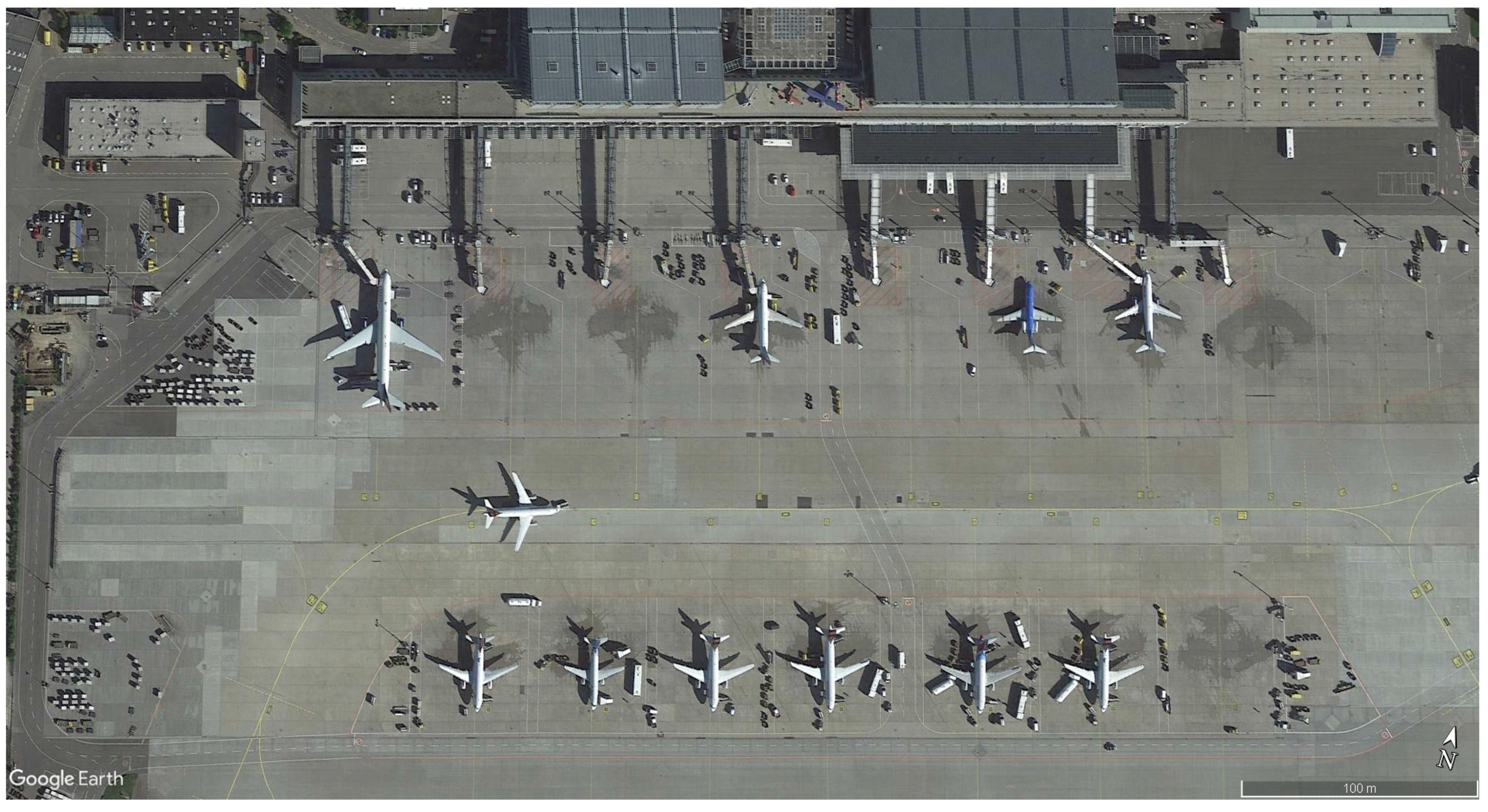
Figure 2.
Aggregated representation of the apron at Stuttgart Airport.

Figure 3.
Detailed representation of Terminal 3.
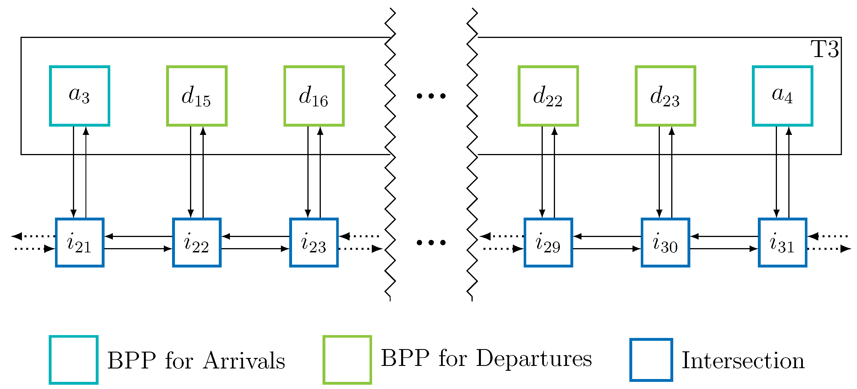
Figure 4.
Detailed representation of request area J.

Figure 5.
Components of the power transmitter system.

Figure 6.
Dynamic wireless charging.
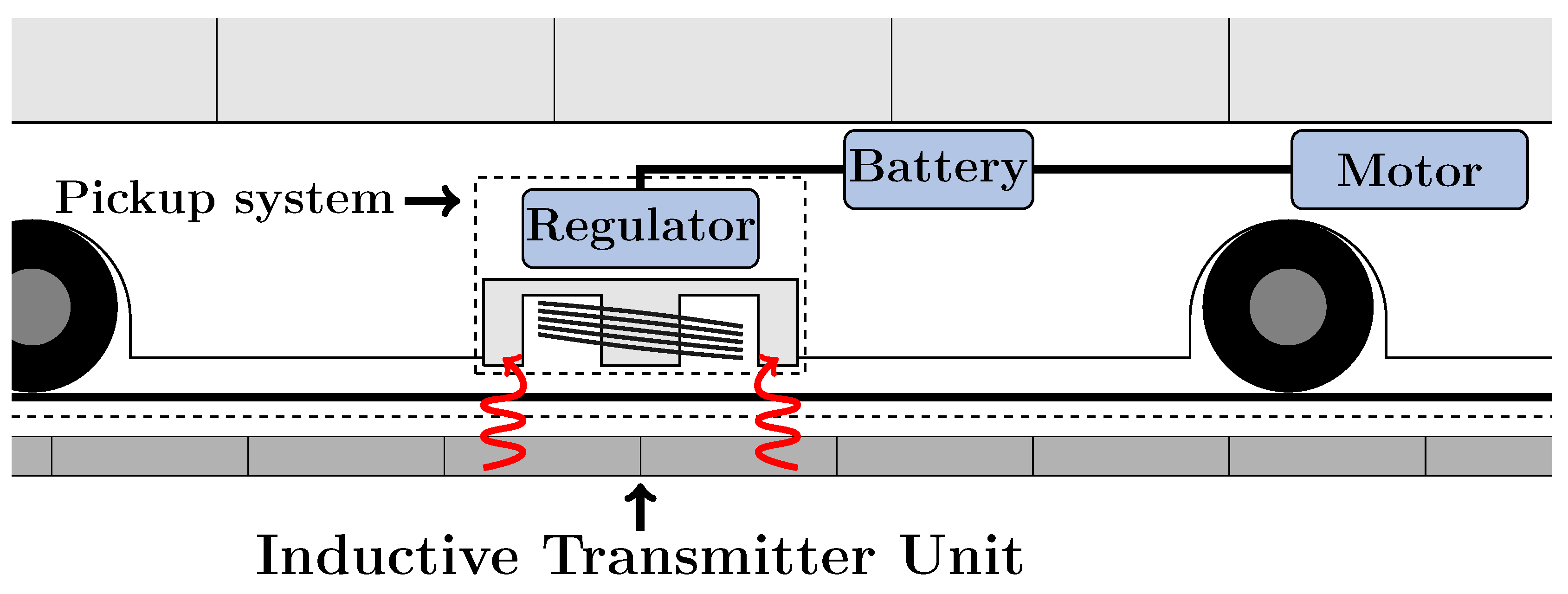
Figure 7.
Dynamic wireless charging.
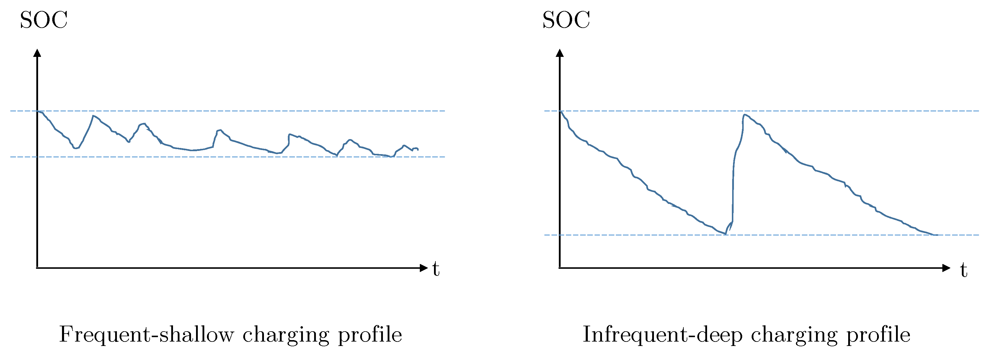
Figure 8.
Selected installation positions for Inductive Transmitter Units (ITUs) connected to a common Power Supply Unit (PSU).
Figure 8.
Selected installation positions for Inductive Transmitter Units (ITUs) connected to a common Power Supply Unit (PSU).

Figure 9.
Fictitious small network.
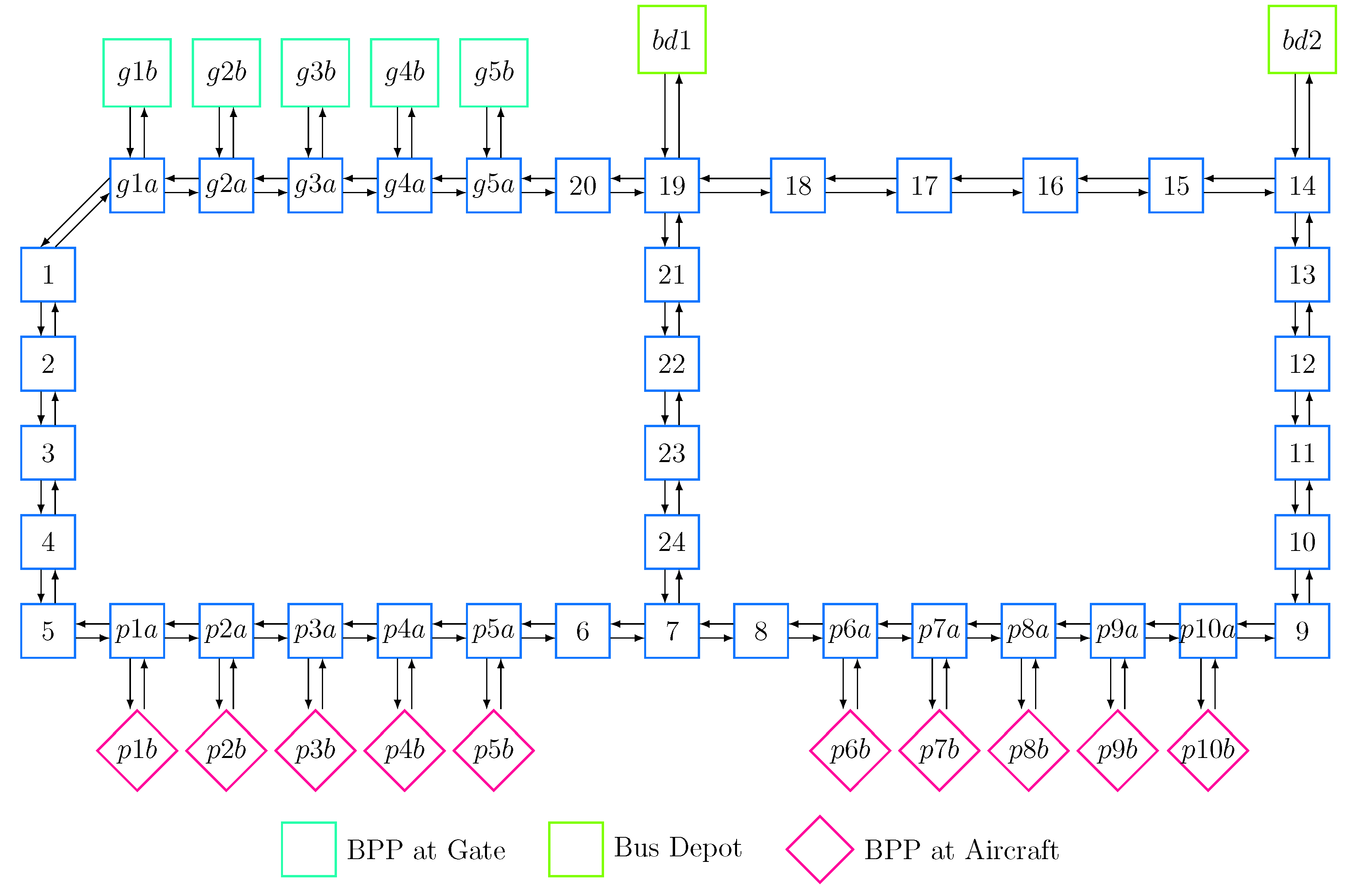
Figure 10.
Allocation of system components for Case A (relatively inexpensive PSUs).

Figure 11.
Allocation of system components for Case B (relatively expensive PSUs).


Table 1.
Notations used in the model.
| Indices and index sets: | |
| links, directed pairs of vertices (nodes) | |
| subset of links potentially equipped with ITUs | |
| subset of links potentially equipped with ITUs and used to serve request r | |
| requests | |
| vertices (nodes) | |
| potential positions for installing PSUs | |
| nodes that can be connected to any PSU | |
| nodes that can be connected to a PSU at node k | |
| nodes immediately preceding node j along a connection from node k to node j | |
| Parameters: | |
| capital requirement for an ITU located on link l | |
| capital requirement for a PSU located at node k | |
| maximum energy consumption required to serve a request r | |
| maximum energy input while traversing link l | |
| number of times link l is traversed while serving a request r | |
| Binary decision variables: | |
| = | |
| = | |
| = | |
ITU—Inductive Transmitter Unit; PSU—Power Supply Unit.
Table 2.
Candidate nodes and links for the wireless charging infrastructure.
| Set of potential nodes to host PSUs | { g1b, g5b, bd1, bd2 } |
| Set of potential nodes to be connected to a PSU | { g1a, g1b, g2a, g2b, g3a, g3b, g4a, g4b, g5a, g5b, bd1, bd2, 1, 2, 12 ... 22 } |
© 2018 by the authors. Licensee MDPI, Basel, Switzerland. This article is an open access article distributed under the terms and conditions of the Creative Commons Attribution (CC BY) license (http://creativecommons.org/licenses/by/4.0/).
Share and Cite
MDPI and ACS Style
Helber, S.; Broihan, J.; Jang, Y.J.; Hecker, P.; Feuerle, T. Location Planning for Dynamic Wireless Charging Systems for Electric Airport Passenger Buses. Energies 2018, 11, 258. https://doi.org/10.3390/en11020258
AMA Style
Helber S, Broihan J, Jang YJ, Hecker P, Feuerle T. Location Planning for Dynamic Wireless Charging Systems for Electric Airport Passenger Buses. Energies. 2018; 11(2):258. https://doi.org/10.3390/en11020258
Chicago/Turabian StyleHelber, Stefan, Justine Broihan, Young Jae Jang, Peter Hecker, and Thomas Feuerle. 2018. "Location Planning for Dynamic Wireless Charging Systems for Electric Airport Passenger Buses" Energies 11, no. 2: 258. https://doi.org/10.3390/en11020258
Note that from the first issue of 2016, this journal uses article numbers instead of page numbers. See further details here.