Development of Automotive Permanent Magnet Alternator with Fully Controlled AC/DC Converter


Electrical Engineering Department, Zarqa University, Zqrqa 13132, Jordan
Energies 2018, 11(2), 274; https://doi.org/10.3390/en11020274
Submission received: 18 November 2017
/
Revised: 8 January 2018
/
Accepted: 9 January 2018
/
Published: 24 January 2018
(This article belongs to the Special Issue Emerging Power Electronics Technologies for Power Systems and Machine Drives)
Abstract
:This paper proposes the design of a three-phase axial flux permanent magnet alternator (AFPMA) that is characterized with an air-cored stator and two-rotor (ACSTR) configuration. The AFPMA is harnessed with fully controlled AC/DC converter using six bridge Insulated Gate Bipolar Transistor (IGBTs) capable to deliver a constant DC output power as an attempt to replace the Lundell alternator for automotive applications. First, the design methodology and analysis of the AFPMA is introduced. The most effective parameters, such as rotor diameter, magnet thickness, number of turns, and winding thickness are determined. A smart digital control which facilitates the comparison between the magnitudes of the three-phase input signals instead of finding the zero crossing points is developed. Moreover, custom design comparators are specially designed and developed to generate adaptive signals that are fed into an Arduino Uno microcontroller. Accordingly, the Arduino generates the timely precise pulses that are necessary to maintain the appropriate triggering of the IGBTs. This technique allows the IGBTs to conduct in an adaptive manner to overcome the problem of asymmetrical voltage outputs from the AFPM alternator. The system is also capable of handling the variation in the speed of the AFPMA via the rigor code in Arduino that detects the change in the supply frequency and voltages in a real time process. The system is first analyzed via simulations using MATLAB/Simulink and then experimentally validated at certain speed and loading conditions. The preliminary tests results indicate that such system is capable to provide an efficient solution to satisfy automotive electric power demands.
1. Introduction
When implementing electrical technology or components into vehicles, the size, weight, cost, performance, and efficiency are the major factors that need to be considered for successful integration. Steadily but surely, automobile manufacturers are looking to improve vehicle component performance and increasing their power density. Among these components is the on-board electrical power charging system which normally consists of the alternator, power converter, and battery. Such electrical systems are pushed to their limits as more and more vehicle’s components are replaced by electrically powered or electrically assisted items. In addition, the evolving customer demands, increasing car functionalities, and developing vehicle regulations and legislations have necessitated the development of the electrical power generating system to satisfy the increasing demands of electrical power in automobiles.
For the last 50 years, the three-phase claw-pole alternators (or Lundell alternators) have been used for the generation of electric power in automotive applications. Until very recent years, this alternator was the most economic choice in vehicle technology due to its low manufacturing cost. However, Lundell alternators suffer from major drawbacks such as reduced efficiency, limited output power, and the need for continuous maintenance. This in turn has limited the utilization of such machines in modern vehicles due to the challenges initiated by increased power demands. Hence, other alternatives for electrical power generating systems have been considered to meet such challenges in motor vehicles [1,2,3,4].
To meet the increasing power demands in modern vehicles, automobile manufacturers have exploited the distinguished merits offered by the rare earth, high power, permanent magnets (PM) in the development of electrical power generator to replace the Lundell alternators.
Alternators utilizing PM offer numerous attractive features over other conventional types of electrical machines, including higher efficiency, higher power density, no maintenance, and better reliability [5,6]. PMs can also improve the dynamic performance, and output quality of the machine. PMs are also becoming less expensive, which makes PM machines more prevalent. The recent advances in power electronic devices have led to better, easier, and cost effective control of PM machines, with the tendency of operating the machine over a large range of speeds while maintaining a reasonable efficiency. Several types of PM machines have been constructed based on their magnetic field direction. For example, PM machines with axial, radial, or transverse configurations have found their way into many applications, such as home appliances, industrial use, renewable energy, and automobiles [7,8,9,10]. Other benefits such as short length, ease of manufacturing and assembly, and modularity are realized by axial flux PM (AFPM) machines when compared to other configurations. Such machines have demonstrated their relative fitness in applications that are limited with confined spaces or those which require direct coupling of the machine with short overhang [11]. AFPM machines can be used for both low speed [12,13] and high speed applications [14,15,16]. Moreover, AFPM machines with ACSTR configurations are characterized with extra advantages such as lower cogging torque, reduced eddy current losses, better output wave (sinusoidal-like) generation, and less harmonics [15] as compared to other types of PM machines with cored stator configurations. Hence they have potential for use in wind energy applications [17,18,19] as well as automotive applications [20,21,22,23].
This paper introduces the design and optimization methodology for an AFPM alternator (AFPMA) as part of the integrated battery charging system in automobiles. The proposed AFPMA, which is intended to work as a replacement for the Lundell alternator diverges from the high speed version that has been previously developed for high speed applications [14,15,16]. The objective is to rebuild that AFPMA with minimal design effort to make it suitable for vehicle applications. This is achieved by redesigning the stator windings within the existing geometrical constraints and without jeopardizing the machine’s efficiency. To do so, the sizing equations for the machine are developed, and the machine performance is analysed using MATLAB/Simulink modelling. Moreover, a three-phase fully controlled AC/DC rectifier is developed and integrated with the AFPMA. The complete system is experimentally tested and simulation results are validated and results obtained are presented in detail in this paper.
The ultimate goal is to design a suitable on-board electrical power system that can satisfy the full requirement of increasing demand of modern automotive industry. The machine shall be capable of providing the car with the necessary power to charge the battery and to turn all electrical and electronics loads whether the engine is running at idle speed or at full speed.
2. Description and Design Requirements of the AFPMA
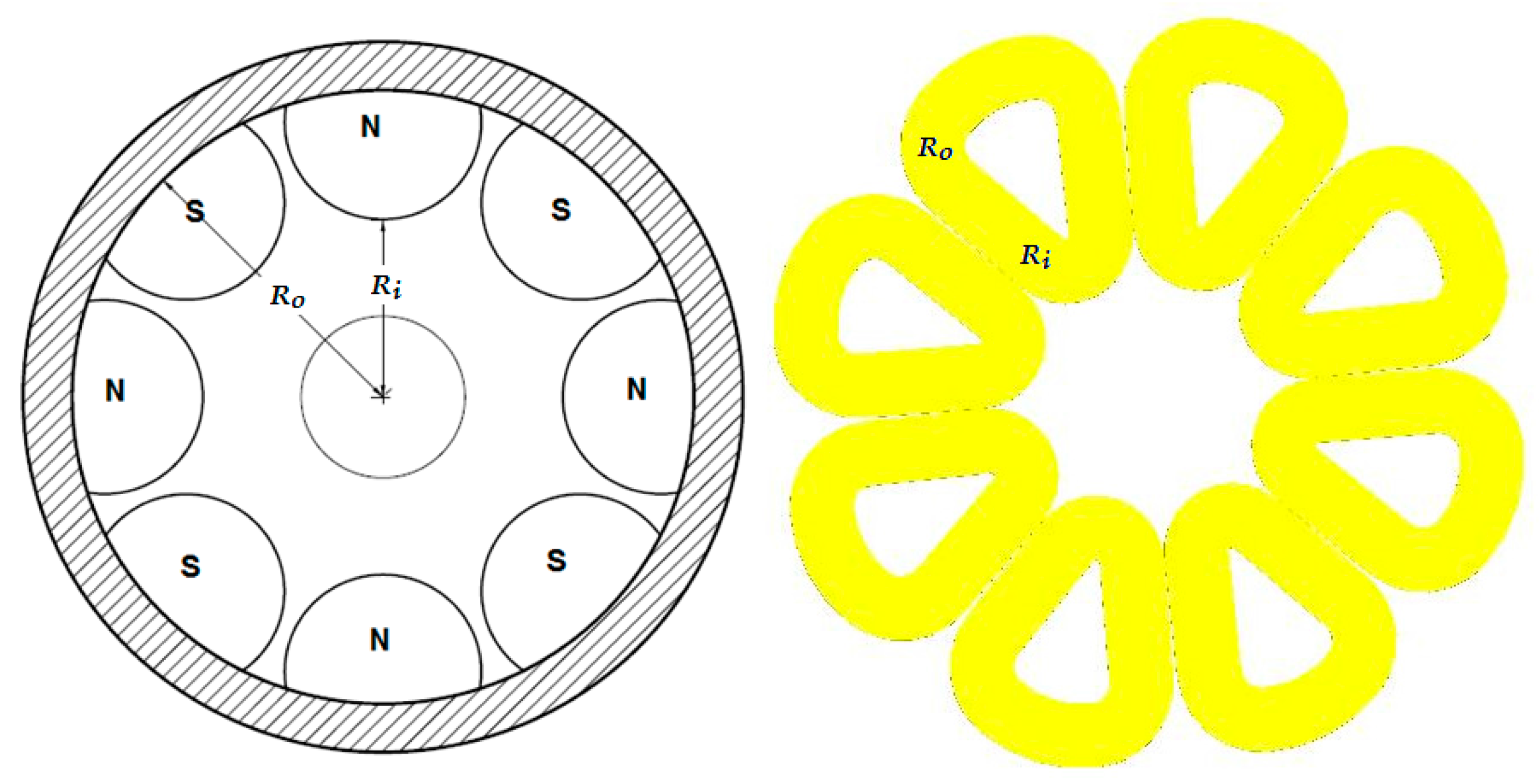
The machine under investigation has an air-cored stator and two-rotor (ACSTR) system with no iron core in the stator coils. Originally, the machine was designed for high speed applications [14]. Hence, the rotors were carefully designed to allow the machine to withstand high levels of centrifugal forces. The proposed AFPMA in this paper is depicted in Figure 1. To redesign the machine for low to moderate speed applications, the rotor configuration and dimensions are kept the same except the retainment ring which encapsulates the rotor magnets are selected from lower cost aluminium alloy instead of expensive, high strength maraging alloy. In addition, simpler manufacturing and assembly processes are performed which in turn reduces the machine cost. However, the stator is completely redesigned in order to achieve the automobile requirements. Still, the stator is air cored (ironless) in order to minimize weight, losses, and cogging torque. Figure 2 shows the main parameters that are considered in the redesign process. These are: the outer radius of the coil which is similar to the outer radius of the PM disc, (), inner radius of coil which is similar to the inner radius of PM disc (), number of winding turns (), axial air gab length (stator thickness), and mechanical speed (). The target is to reconstruct a mathematical model that can be used to design the stator winding to fit for the AFPMA to achieve the machine requirements presented in Table 1 within the existing constraints.
3. Design Consideration and Sizing of the AFPMA
In order to facilitate the AFPMA for automobile applications, the machine shall be designed to fit for the gasoline engine speed. However, coupling the alternator directly to the automobile engine will require an increased number of stator winding turns to compensate for the low operating speed, thus increasing overall machine volume. Lundell alternators are therefore commonly run with a belt ratio of 3:1 to obtain a higher rotational speed. For the proposed AFPMA, a belt ratio of 5:1 is adopted to achieve higher rotational speed hence increasing the overall power density of the system. Accordingly the AFPMA shall be capable to operate in the range of 3750–15,000 rpm when coupled to an engine running in the range of idle speed of 750 rpm to the cruise speed of 3000 rpm. As far as the mechanical integrity is concerned, the AFPMA has its PMs encapsulated by a high strength retainment ring that is shrunk fit on the rotor disc. Mechanical integrity tests showed safe operation of the machine at rotational speeds in the excess 25,000 [16]. However, in this paper, and for the purpose of laboratory testing, the proposed machine is driven by a three-phase electric motor with a belt ratio of 1.7:1 which will limit the machine maximum speed of the AFPMA to 5100 rpm.
Once the range of operating speed is known, it is possible to develop the necessary sizing equations and mathematical models that can be utilized for optimization purposes in order to determine the machine’s parameters within the competing demands to meet the system requirements.
To derive the necessary equations, the induced voltage formula will be applied on the stationary conductors in the presence of a rotating magnetic field. The rotating magnetic field in the proposed machine is secured by the axially magnetized PM semicircular discs that are located alternately on both rotor sides. The induced voltage in the conductor relies on the flux density, conductor length, and relative velocity. Calculation of the flux density in the middle of the air gap relies on several parameters such as: magnet type/grade, magnet axial length , magnet shape and air gap length between the two PM rotors. In automotive applications, components in the engine compartment are fitted in confined spaces and often exposed to high ambient temperatures and insufficient cooling. Mounted near the engine, the alternator is exposed to high temperatures, thereby reducing its performance and lifetime. Therefore, PM alternators have to be designed with great care to avoid the risk of PM demagnetization, especially for the NdFeB which has a lower Curie temperature and lower working temperature. In automotive applications, the under hood temperature may vary in the range from 50 °C to 80 °C, adding more thermal stress on the PM alternator as it may increase the risk of PM demagnetization. Therefore, selecting the type and the grade of PM is a vital issue in the design process as one has to compromise between achieving higher power density and higher temperature operability. Among the recently developed PMs, comes the neodymium iron boron (NdFeB) magnet which has high remanence , high coercive force , high energy production, and a high performance/cost ratio. As can be shown in Figure 3, NdFeB magnets with grade N52 have the highest normalized energy product (with average remanence value of 1.45 T) which makes them the most powerful magnets among other grades. However, such magnets have a limited operating temperature of 80 °C which may degrade the performance of the proposed AFPM alternator when used for automotive applications. In this stage of research, it was decided to choose the type and grade of PM that provides the best magnetic characteristics in order to achieve the maximum possible power density of the AFPM alternator to perform as an advanced development model (ADM). The objective is to prove that the AFPMA would perform according to the requirements and interface well with other systems in terms of form, fit, and function (F3). Thanks to its simple shape and design, the ACSTR configuration of the proposed AFPMA allow for natural ventilation and heat removal with minimal effort. The NdFeB magnets are held by an Alumec carrier which in turn plays a crucial role in dissipating the heat that may transfer from the stator windings to the rotor surface. In addition, the rotating PM discs work as natural ventilators since they continuously expel the hot air surrounding their surfaces during rotation. Consequently, once the performance of the machine is experimentally validated, the engineering development model (EDM) of the AFPMA will consider the intended final materials and/or deployment of the necessary cooling arrangement to account for reliability, availability, and maintainability (RAM).
To account for temperature effect on the energy product of the PMs hence on the machine performance, and are calculated respectively as [25]:
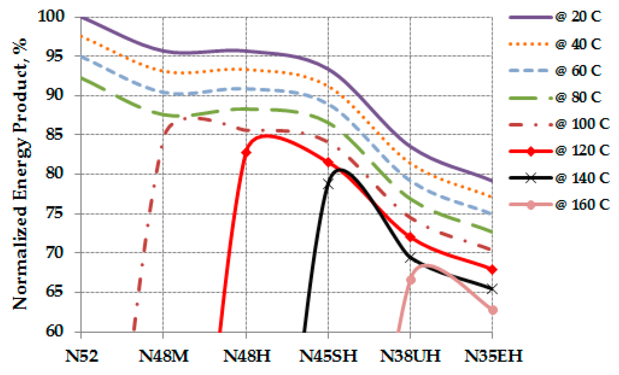
where and are the NdFeB grade 52 remanence and coercive force respectively given at 20 °C, and are the temperature coefficients for and and they are set to −0.12 and −0.6 respectively, and is the PM temperature which is set to the maximum operating temperature of 80 °C. Accordingly, the remanence value and energy product are calculated for N52 at the maximum operating temperature which showed a decrease in the normalized energy product by approximately 8%. The effect of temperature rise on the normalized energy product for several grades of NdFeB as compared to the energy product of N52 based on 20 °C is presented in Figure 4.
For simplification purposes, circular magnet shapes are considered to determine the magnetic flux density in the air gap between the two PM rotors. The full derivation of the sizing equation and other necessary equations for the AFPMA’s parameter determination and optimization purposes are shown in Appendix A.
4. Optimization of the AFPMA
In order to optimize the machine design, two main characteristics will be investigated. These are machine efficiency and machine internal power factor, as will be described in detail in the following sections.
4.1. Machine Efficiency
To predict the machine efficiency, the losses that are affected by the redesign process of the stator will be investigated. The two main losses that are seen to have major impact on the efficiency of the redesigned AFPMA these are the stator copper losses and the windage losses. The copper losses, , are calculated at the designed armature current, A as:
The windage losses of the machine is highly dependent on the rotor diameter and the rotational speed. If the rotor diameter is kept constant, then the only parameter that affects the windage losses is the rotor speed as:
where is the coefficient drag for turbulent flow, is Reynolds number, is number of rotating discs, is the specific density of the surrounding air = 1.18 kg/m3, is the coefficient of viscosity of the air = 1.98 × 10⁻⁵ kg/m·s, and is shaft radius.
Moreover, the amount of saving in windage losses is a critical aspect which may diversely affect the overall performance of the machine if precautions are not considered during the design. Hence, for fixed rotor geometry, the windage losses will only vary as a function of the rotor speed as:
The maximum windage losses are obtained at the maximum calculated speed, and minimum number of winding turns. i.e., at = 2.
Accordingly, the saving in the windage losses can be calculated as:
Assuming unity load power factor, and rated armature current of 40 A, the machine output power can be calculated as:
Assuming the machine is operating at unity power factor, the full load phase voltage is calculated as:
Other losses, such as rotor eddy current losses, are not considered in the investigation since the rotor geometry is not changed. Hence, the machine efficiency, at the rated armature current and unity load power factor is calculated as:
4.2. Machine Internal Power Factor (cos φ)
The machine internal power factor (PFm) can be calculated as , where . Also, the voltage regulation of the machine can be calculated as:
The no load voltage equals the per phase internal generated voltage of the machine . Hence, .
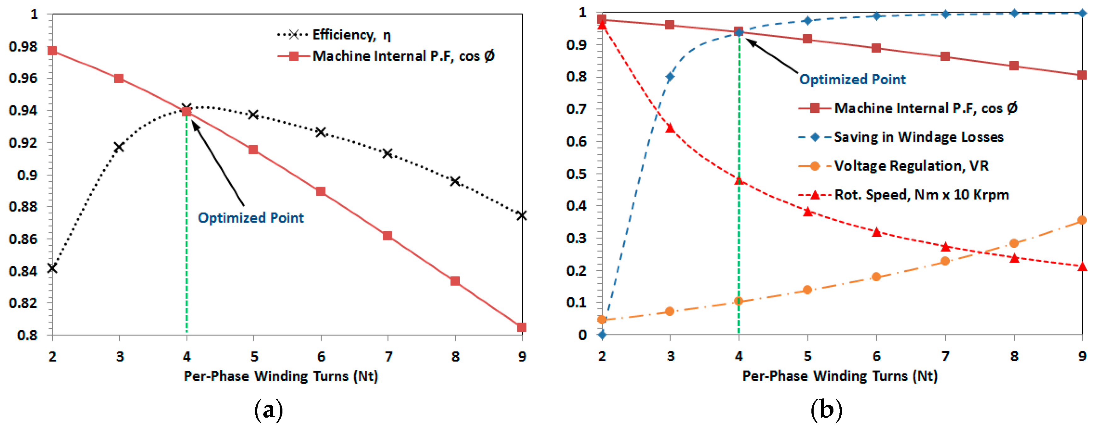
To perform the optimization, the number of turns per pole per phase is varied in steps in the range from two turns up to nine turns. The maximum number of turns is limited with the space between the shaft and magnet inner radius. For a specific number of turns, the corresponding rotational speed, power factor, saving in windage losses, voltage regulation, and efficiency are calculated. Using the set parameters found in Table 2, the first group of results is graphically presented to show the machine efficiency and the internal power factor against the change in number of turns (eventually the speed) as shown in Figure 5a. The second group of results are also arranged to show the saving in windage losses, voltage regulation, and rotational speed against the change in number of turns as shown in Figure 5b. Such graphs are utilized to assist in selecting the best combinations of machine performance characteristics hence, the calculated parameters as summarized in Table 3. It can be seen from the results that the optimum design is obtained at = 4 turns where = 0.94 and efficiency of 94% is achieved. Moreover, at this point the saving in normalized windage losses is 93% and the design speed () of 4814 rpm is achieved. The line–line RMS output voltage is dependent on the AFPMA speed. Hence the machine voltage/speed constant which correlates the AFPMA line–line RMS output voltage to its rotational speed can be found as .
5. Modelling and Simulation of the AFPMA
The AFPMA under consideration has its magnet topology designed to produce a sinusoidal flux in its ironless stator. This implies that the induced voltages will be almost sinusoidal. MATLAB/Simulink R2012a (Mathworks, Galway, Ireland) [27], has a block that is already defined in the SimPowerSystems which is called a permanent magnet synchronous machine (PMSM). This block is used to simulate the performance of the AFPMA under consideration after setting the corresponding parameters as shown in Figure 6.
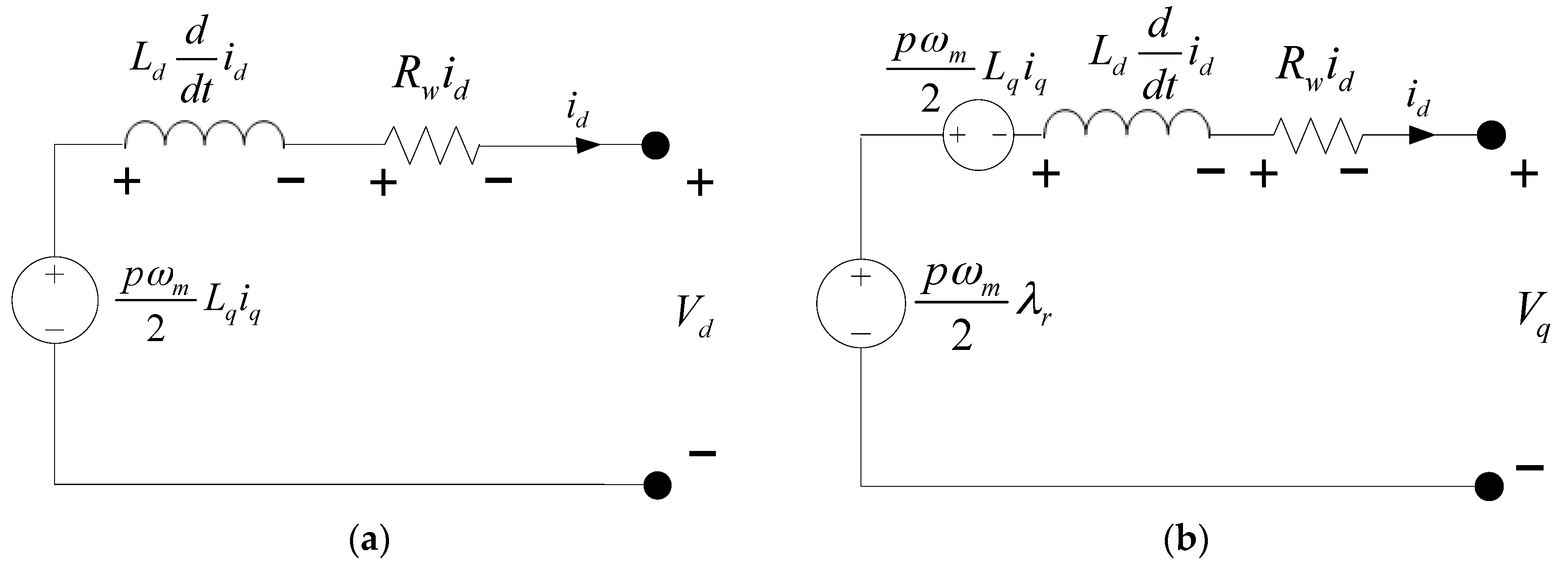
The AFPMA equivalent circuit is depicted in Figure 7, whereas the corresponding mathematical model of the machine in rotor reference frame (dq-axis) is summarized in Appendix B.
Once the parameters of the AFPMA are defined, MATLAB/Simulink model can be used to predict the machine performance at several conditions which can be further analyzed after experimental validation. The expected line–line rms voltages of the machine at no load and for several rotational speeds are represented in Figure 8.
6. Development of the Controlled AC/DC Rectifier for the AFPMA
Regulation of the output voltage is a key issue in automotive alternator. The output voltage of the alternator shall be maintained at about 14 V DC, which is the nominal charging voltage of a 12 V lead–acid battery. The Lundell alternator regulates its output voltage by controlling the current supplied to the filed windings hence the magnetic flux inside the alternator. In PM machines where the flux is relatively constant, the back-emf is only proportional to the alternator’s speed. Therefore, driving the machine above the rated speed will generate a back-emf that is exceeding the rated output voltage. Accordingly, at top speed the power electronic components in the converter shall be capable to withstand both rated current and the considerable machine back-emf which may involve increased power electronics cost and complexity. This could be solved by employing a DC-to-DC or controlled AC-to-DC converter to maintain a constant output voltage. The separate converter can be mounted in a location where the temperatures and vibration levels are lower. When used together with an IGBT based AC/DC converter, the alternator can respond in a fast manner to provide the required charging current, at a stable voltage, over a large range of rotational speeds.
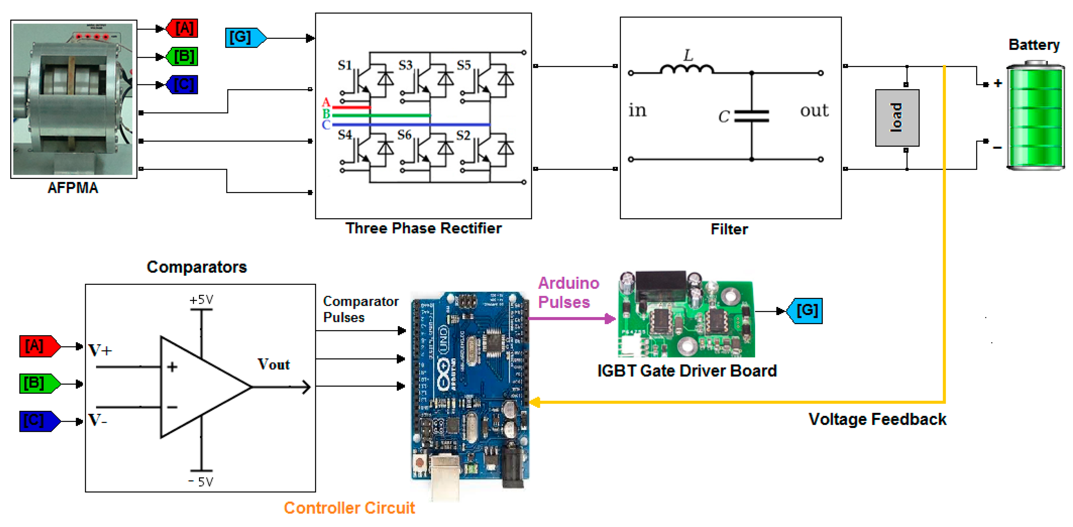
The regulation and control of alternator’s output has been described in a number of studies [28,29,30,31]. Most of this work relies on using the Pulse Width Modulation (PWM) and boost rectifier technique. Published research on the integration and implementation of fully controlled AC/DC converter to PM generators is still scarce. In this paper, the description of the development of three-phase full wave fully controlled rectifier system using six IGBT bridge will be demonstrated to regulate the output of the AFPMA. As shown in Figure 9, the proposed system will utilize smart digital control using specially designed comparators interfaced with Arduino Uno to generate the required pulses to the gate of the IGBTs. The proposed system shall be capable to operate under several conditions such as variable input voltage, variable input frequency, various loading conditions. The objective is to supply a regulated DC voltage to a vehicle’s battery and loads under varying alternator speeds.
The following main components form the corner stones of the fully controlled AC/DC converter:
- IGBT six-pack module (CM100TF-12H)
- Microcontroller (Arduino Uno)
- Comparator circuit (voltage sensing).
- LC filter.
6.1. Control Scheme
To obtain the required and regulated DC voltage, the IGBT switches have to be triggered at a proper time and sequence. The voltages of the three phases from the AFPMA are measured instantaneously to determine the most positive phase and the most negative phase using comparator circuitry that is shown in Figure 10. It compares two phases (AB, AC, BC) amplitudes and generates a pulse at the output if the phase at the non-inverting input is higher than the phase at the inverting input. The generated pulses are fed to Arduino via a special conditioning circuit and then a decision is made to trigger two specific switches of the IGBT. The switching scheme is based on a specific combination sequence as shown in Figure 11. To keep the output voltage at a specific (preset value) voltage, the DC output from the filter is then compared with the voltage set point and if the output voltage is lower than the set point, the rectifier will be activated accordingly.
6.2. Controlled Rectifier Design Calculations
The three phase full wave fully controlled rectifier is implemented using six IGBTs connected in the form of a full wave bridge configuration. All the six IGBTs are controlled switches which are turned on at appropriate times by applying suitable gate trigger signals. The average output voltage of the rectifier can be calculated as [32]:
where is the rms line voltage from the three-phase AFPMA and is the firing angle applied to the IGBT gate.
The AFPMA output voltage is regulated by controlling the firing angle of the IGBTs. To obtain a constant output voltage, a feedback signal must be sent to the controller to compare it with the preset value of 14.3 V to allow for controlled battery charging operation. When the battery is fully charged, the controller keeps the firing angle at 90 degrees. When the battery charge goes below the preset level, then the controller triggers the IGBT with a firing angle below 90 degrees which is proportional to the voltage difference. The higher the voltage difference, the lower the firing angle will be.
The minim line–line RMS voltage that is required to achieve the preset value of 14.3 V for the battery charger at degree can be determined from (13) as:
Rearranging for
The minim speed of the AFPMA, that keeps the output voltage at the preset value while considering the machine constant value can be calculated as
At the design speed, , the line–line RMS output voltage will be 17.6 V and the line-line peak output voltage, will be 24.89 V. Hence the maximum rectifier output voltage, at will be 23.7 V. The predicted results for AFPMA voltage and rectifier voltage with respect to speed are summarized in Table 4.
.
7. Overall System Simulation
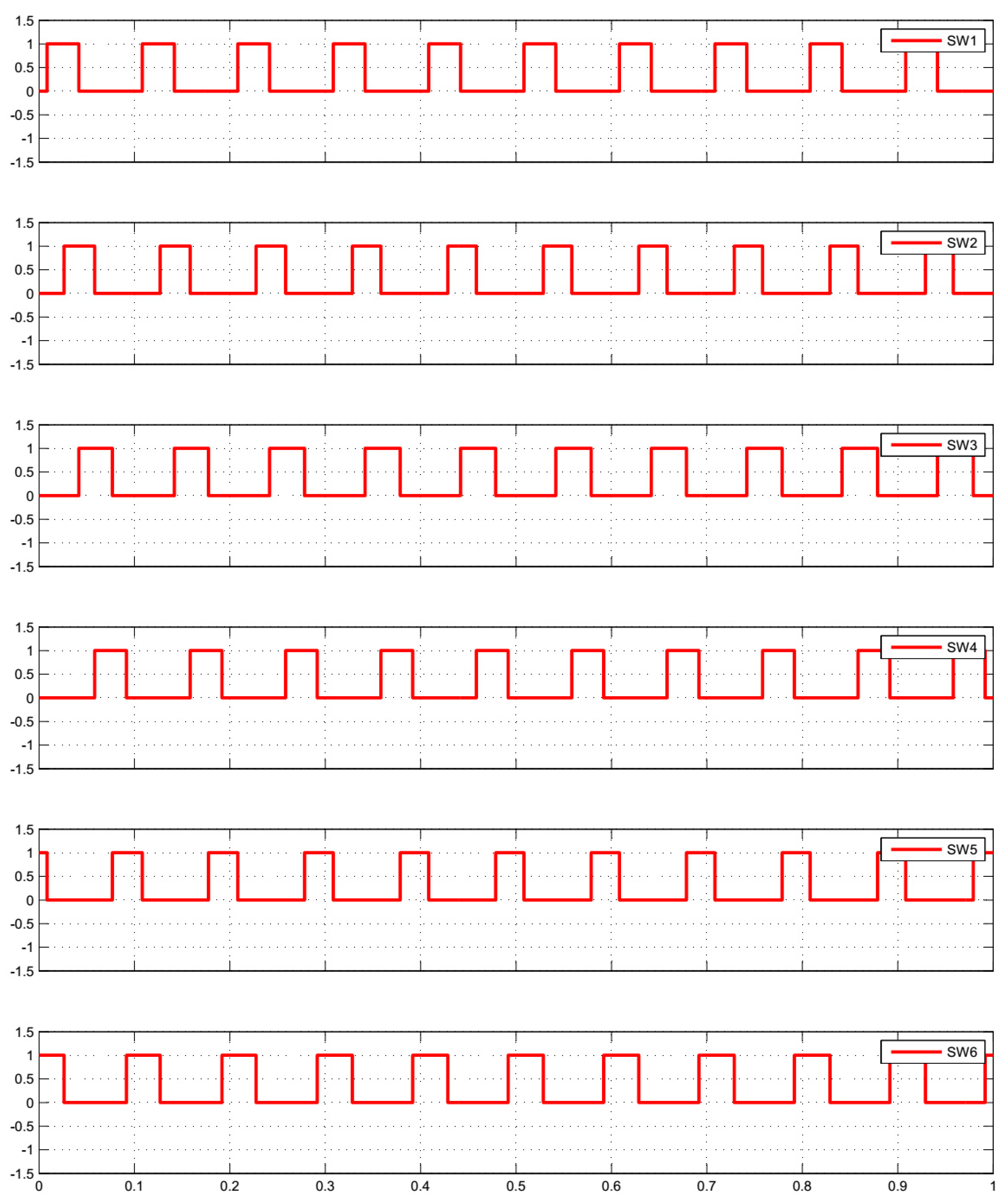
The complete system that includes the AFPMA, integrated with the three-phase fully controlled AC/DC converter, LC filter, battery, load, and controller is modeled using MATLAB/Simulink as shown in Figure 12. The controller design relies on the measurement of the AFPMA output voltages where both most positive and negative phases are determined at a certain instant. Based on the feedback signal from the battery side, the controller generates the necessary pulses to trigger the IGBT switches accordingly. For simulation purposes, logic OR gates are used to implement the switching sequence that was presented in Figure 8. The algorithm that is used to enable the controller is depicted in Figure 13. Whereas the controller output zero-one pulses are depicted in Figure 14.
In practice, charging system in an automobile shall be capable to operate at various loads and various engine/alternator speed while supplying a regulated/fixed voltage to battery terminals and any loads connected across the terminals. In the following section, simulations for different scenarios are developed in order to predict the system behavior at various operating conditions.
7.1. System Simulation with Open Circuit
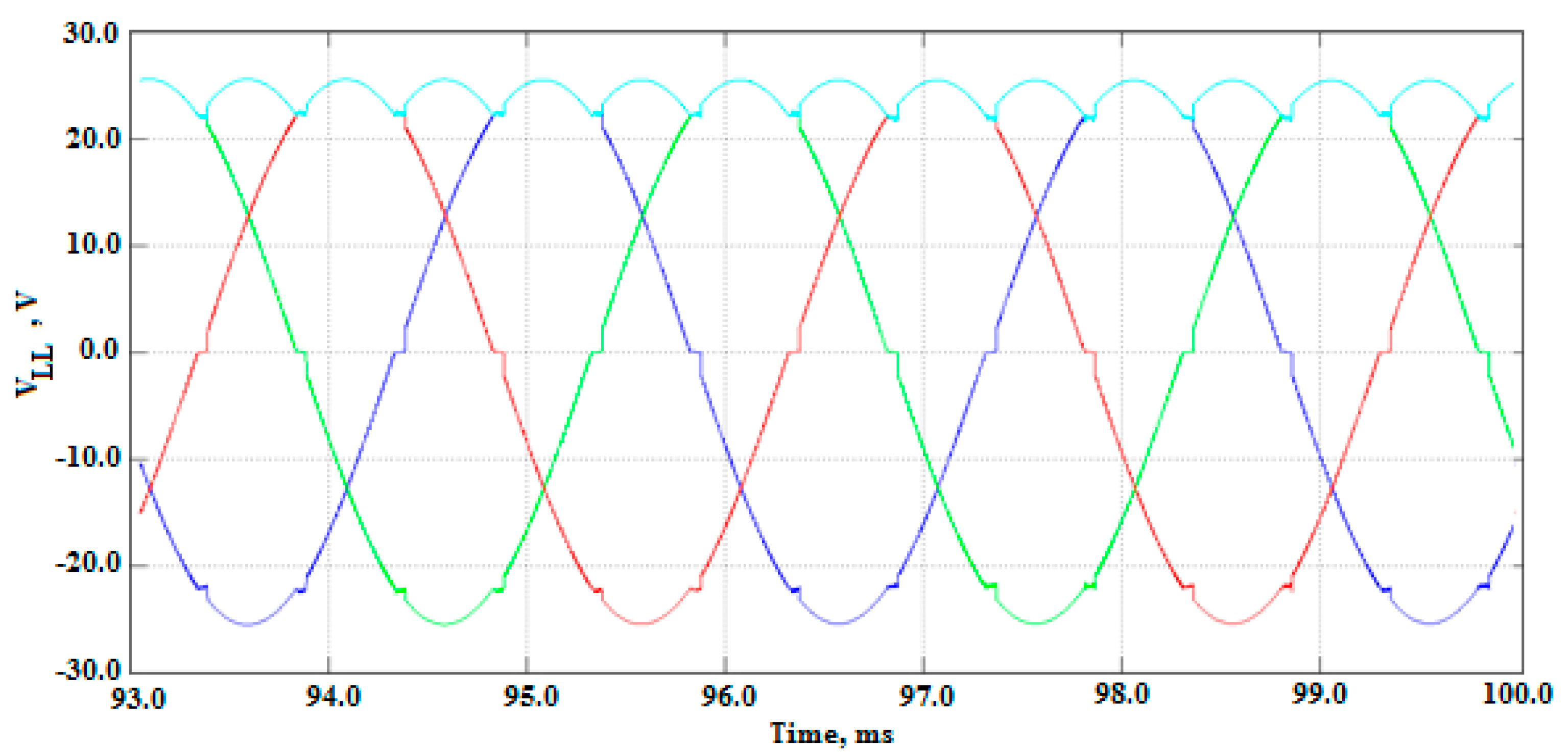
In this scenario, the AFPMA speed is set to 5000 RPM, the load and the battery are disconnected from the rectifier terminals, and the firing angle is set to zero. The six pulse rectified output as a result from the simulation is shown in Figure 15. The AFPMA line–line peak voltage is found to be 24.8 V, hence the rectifier output voltage is found to be 23.7 V. Such initial simulation results are validated by comparing them to the analytical results that are presented earlier in Table 4. Hence other simulation scenarios can be conducted with more confidence.
7.2. System Simulation with Constant Load and Variable Speed
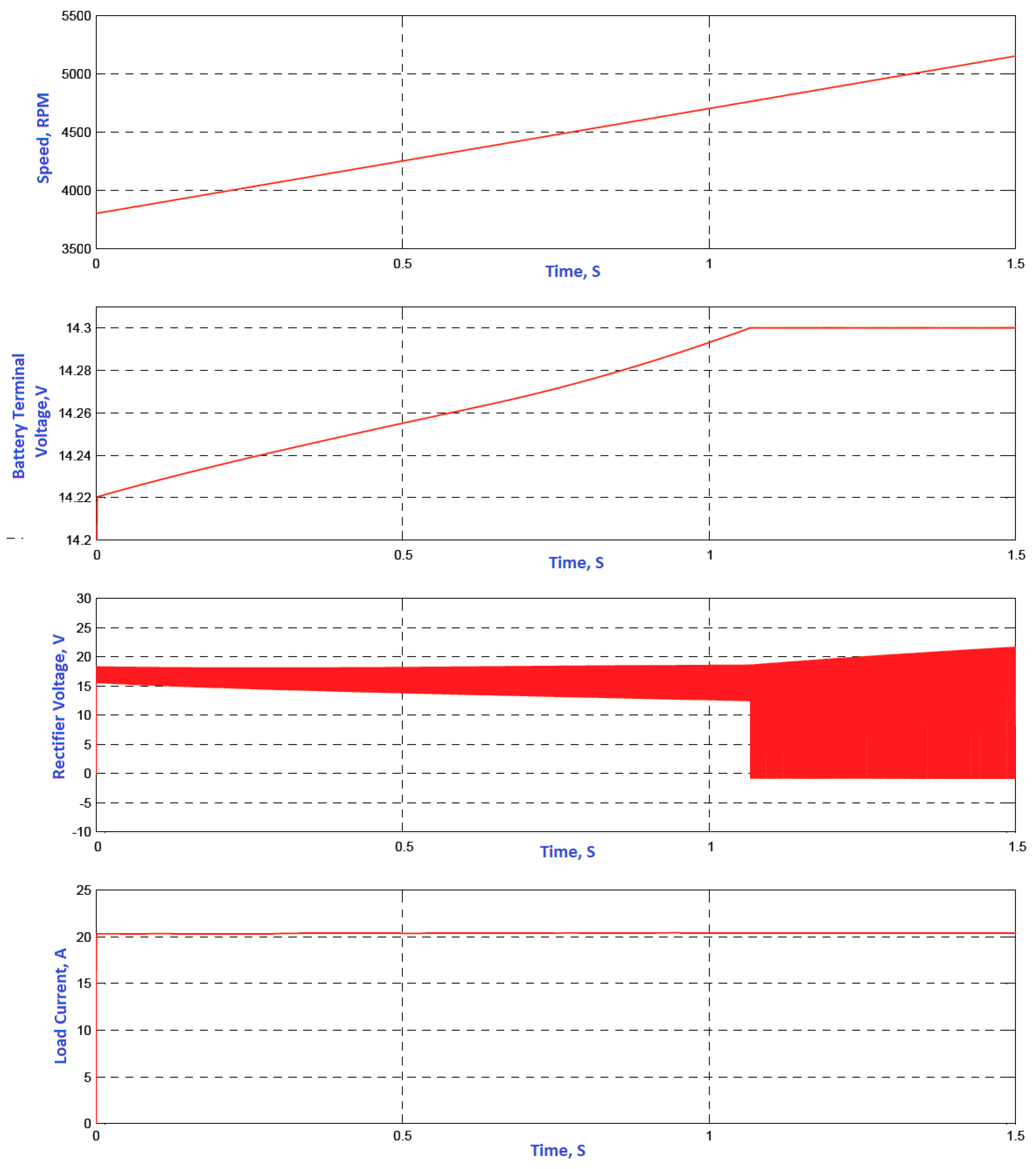
In this scenario, a constant electrical load of 0.7 Ω is fitted across the battery terminals while the speed of AFPMA is ramped up from 3800 RPM to 5100 RPM through the simulation runtime. Simulation results are depicted in Figure 16 where battery terminal voltage (after filter), rectifier voltage (before filter), and load current are captured in response to speed variation with respect to time. The charging limit for the battery is set to 14.3 V.
7.3. System Simulation with Constant Speed and Variable Load
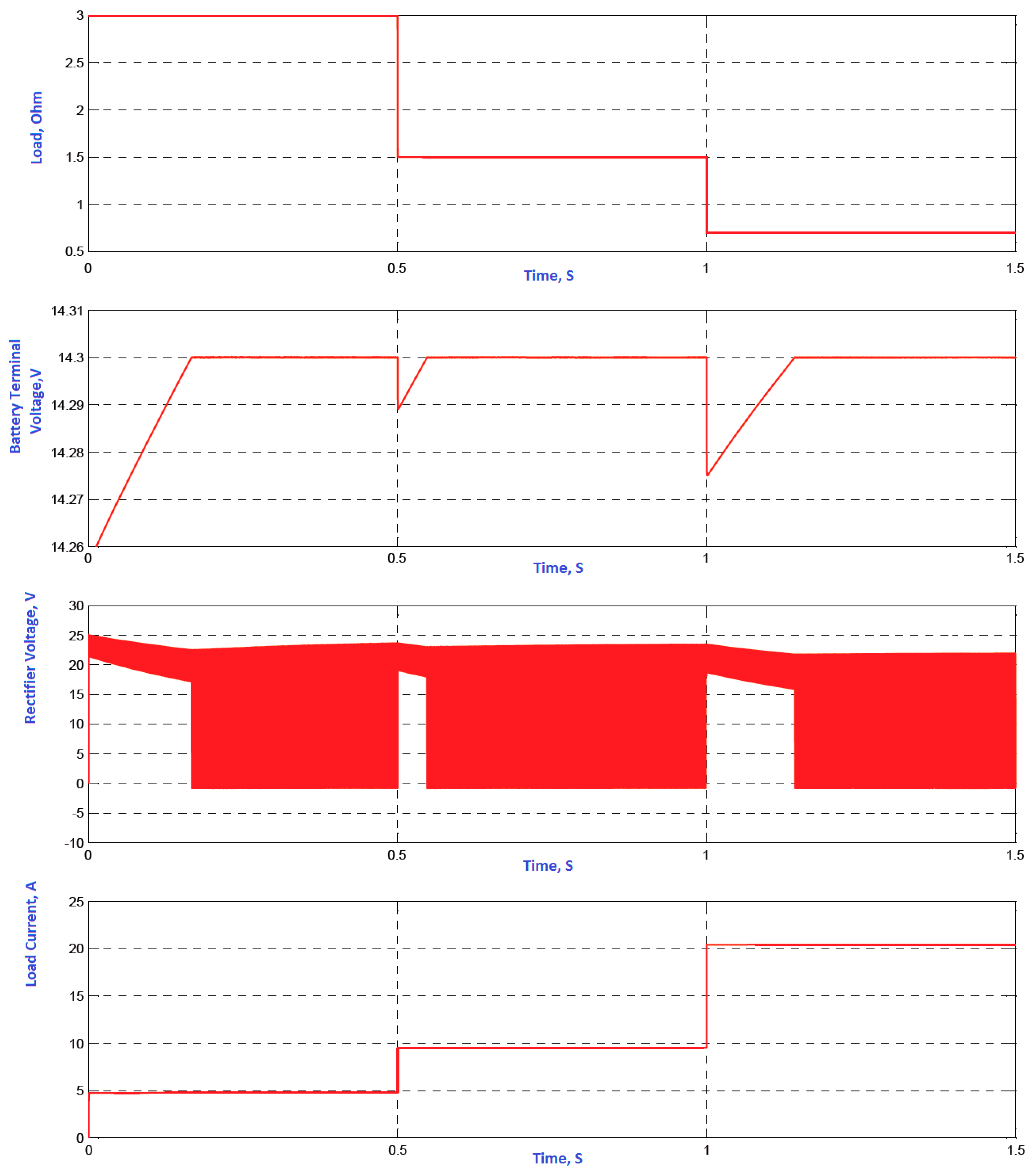
In this scenario, the speed of AFPMA is set to 5100 RPM while the is electrical load connected across the battery terminal is decreased from 3 Ω to 0.7 Ω of through the simulation runtime from 0 to 1.5 s. Simulation results are depicted in Figure 17 where battery terminal voltage (after filter), rectifier voltage (before filter), and load current are captured in response to electrical load variation with respect to time. The charging limit for the battery is set to 14.3 V.
7.4. System Simulation with Variable Speed and Variable Load
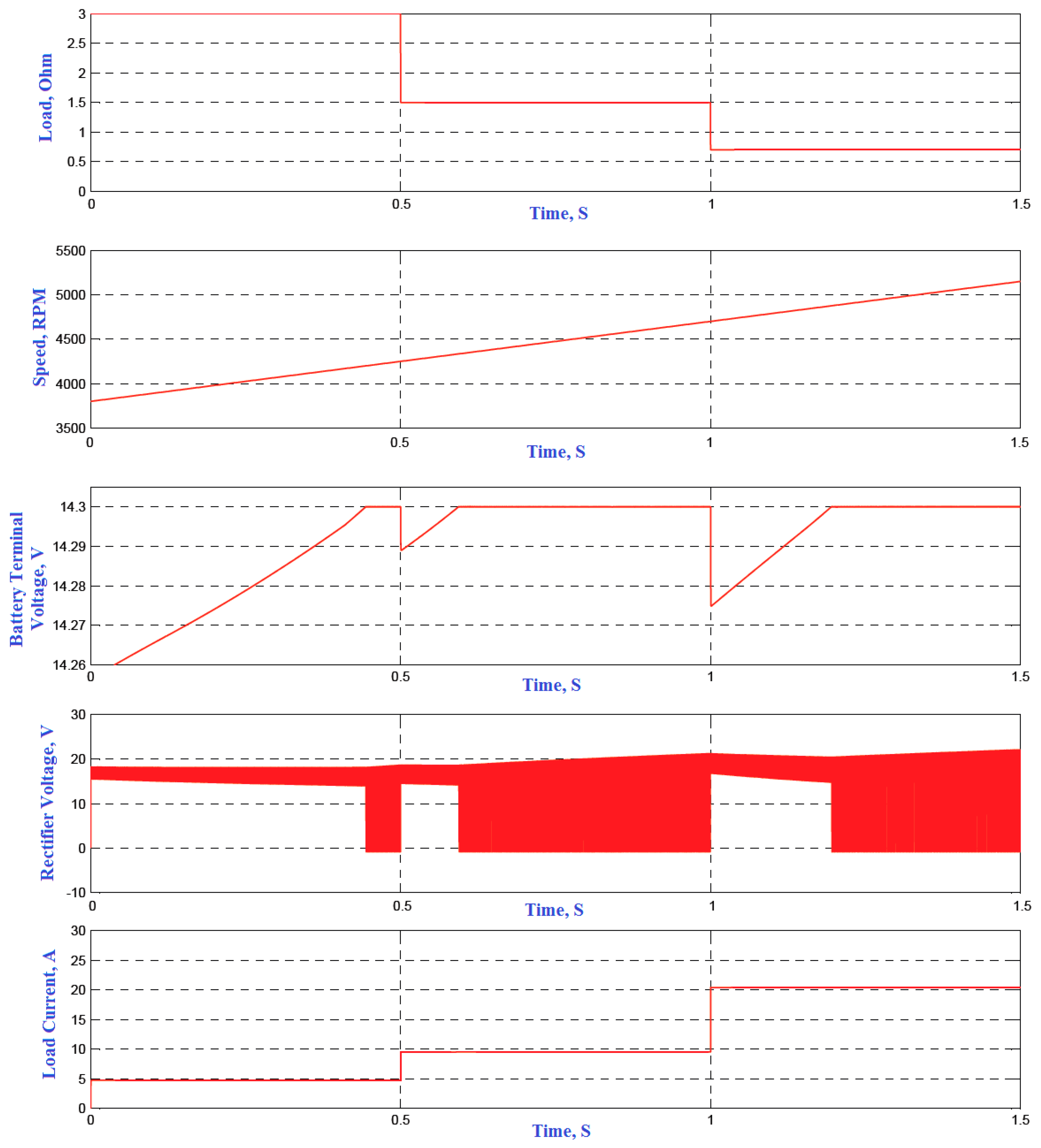
In this scenario, both speed of AFPMA and electrical load are varied simultaneously. The speed is increased from 3800 RPM to 5100 RPM while the electrical load across the battery terminal is decreased from 3 Ω to 0.7 Ω of through the simulation runtime from 0 to 1.5 s. Simulation results are depicted in Figure 18 where battery terminal voltage (after filter), rectifier voltage (before filter), and load current are captured in response to electrical load variation with respect to time. The charging limit for the battery is set to 14.3 V.
8. Testing and Experimentation of the AFPMA
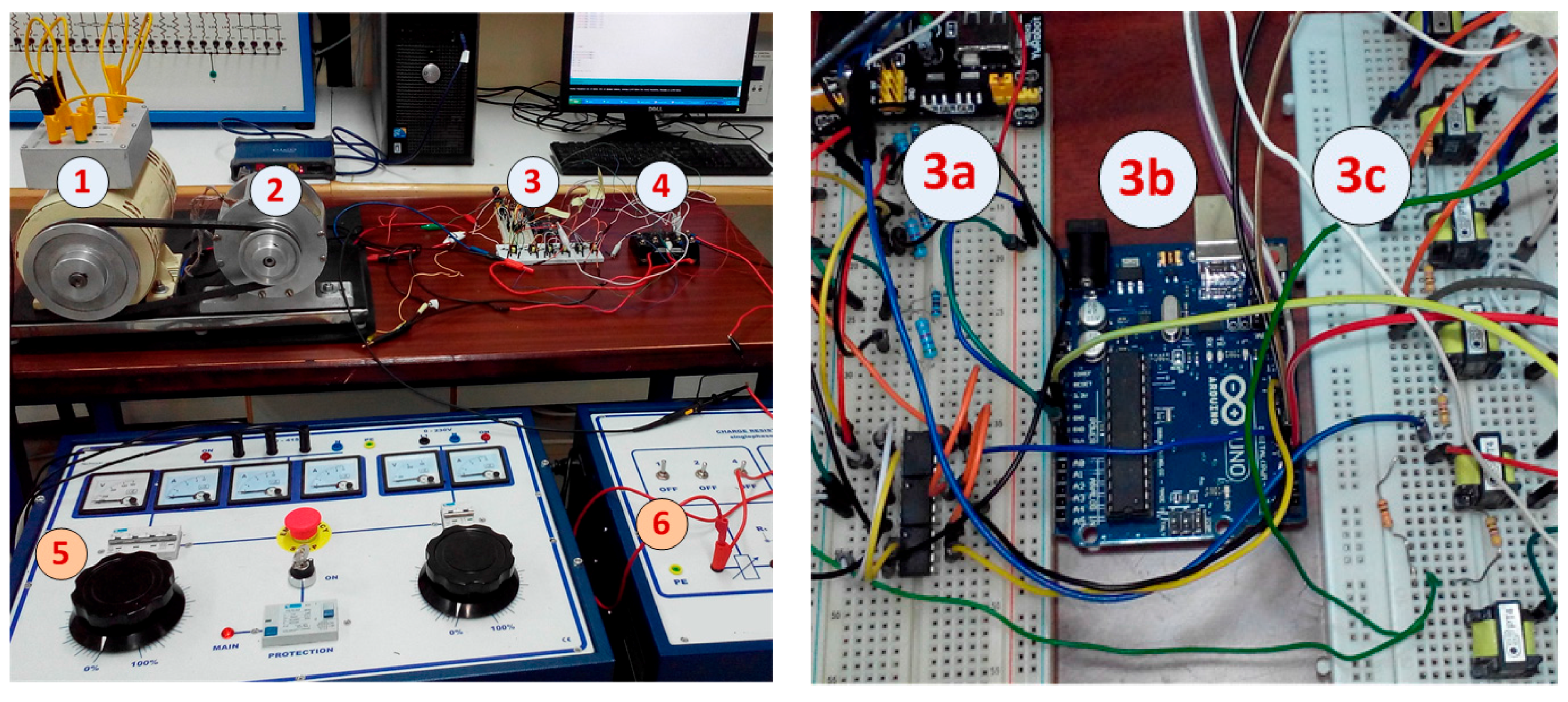
The AFPMA along with the controlled AC/DC converter are experimentally tested to obtain their performance characteristics as shown in Figure 19. As an alternative prime mover to the car engine, a three-phase electrical motor that is fed from three-phase variable power supply is used to drive the AFPMA at several speeds through pulleys and belt. A dummy resistive load is used to test the system under various loading conditions. The three-phase output from the AFPMA is fed to the electrical load through the IGBT which is fully controlled via the controller circuit. The controller circuit contains the comparator circuit, Arduino Uno, and the IGBT gate driver circuit. To demonstrate the system performance at several operating conditions, the following tests are performed as described below.
8.1. No Load Tests
In this section, the system is tested under no load condition with AFPMA initially is running at rated speed of 5000 RPM. The line–line output voltage from the AFPMA is captured and compared with the simulation results obtained from MATLAB as shown in Figure 20. Results obtained show a good match between the simulation and experimental results. The results of the three-phase line-neutral voltages are captured using PicoScope 3000 oscilloscope (Pico Technology, Cambridgeshire, UK) as depicted in Figure 21. The quality of the AFPMA voltage signal is also analyzed where the total harmonic distortion (THD) is found to be close to 2% as shown in Figure 22. The output from the rectifier at zero firing angle is also captured in Figure 23. It is shown from the results that the rectified output voltage is very close to the output obtained from the simulation results. It is also shown that phase C has its peak line–line voltage less than the other two phases by 1.5 volts. This is explained by the fact that the coil that is responsible for phase C is physically located between the other two phases in the middle of the air gap. Therefore, less magnetic flux density arrives from PM to that location, hence less induced voltage is produced in that coil. This makes the output voltage asymmetrical and special precautions have to be taken into consideration when designing the scheme for the controller of the converter.
The controller of the AC/DC converter is designed to deal with the voltages under asymmetrical conditions. It is the comparator that gives the controller the adaptively feature as it compares the most positive signal with the most negative one. Therefore, an adaptive pulse is generated from the comparator that is proportional to the difference between the two consecutive phases. Even in an asymmetrical situation where the three phase voltages are not balanced, the comparator is capable to create the necessary pulse and send it to Arduino Uno to generate the necessary pulses for triggering the appropriate switches in the IGBT module. For example, Figure 24 shows the output from the comparator for C and phases A. When C phase (blue color) is most positive than phase A (green color) the comparator generates the appropriate pulse (yellow color) throughout that interval. The results also show that the peak value of phase A is higher than that for phase C. As a result, an adaptive pulse is generated from the comparator witnessed by an increase in the pulses width (yellow color). The output from the comparators are sent to Arduino Uno where the appropriate train of pules are generated and sent to IGBT gate driver circuit from which the IGBT switches are triggered accordingly. As can be shown from Figure 25, the six Arduino pulses have different widths to allow for adaptive control of the AC/DC converter.
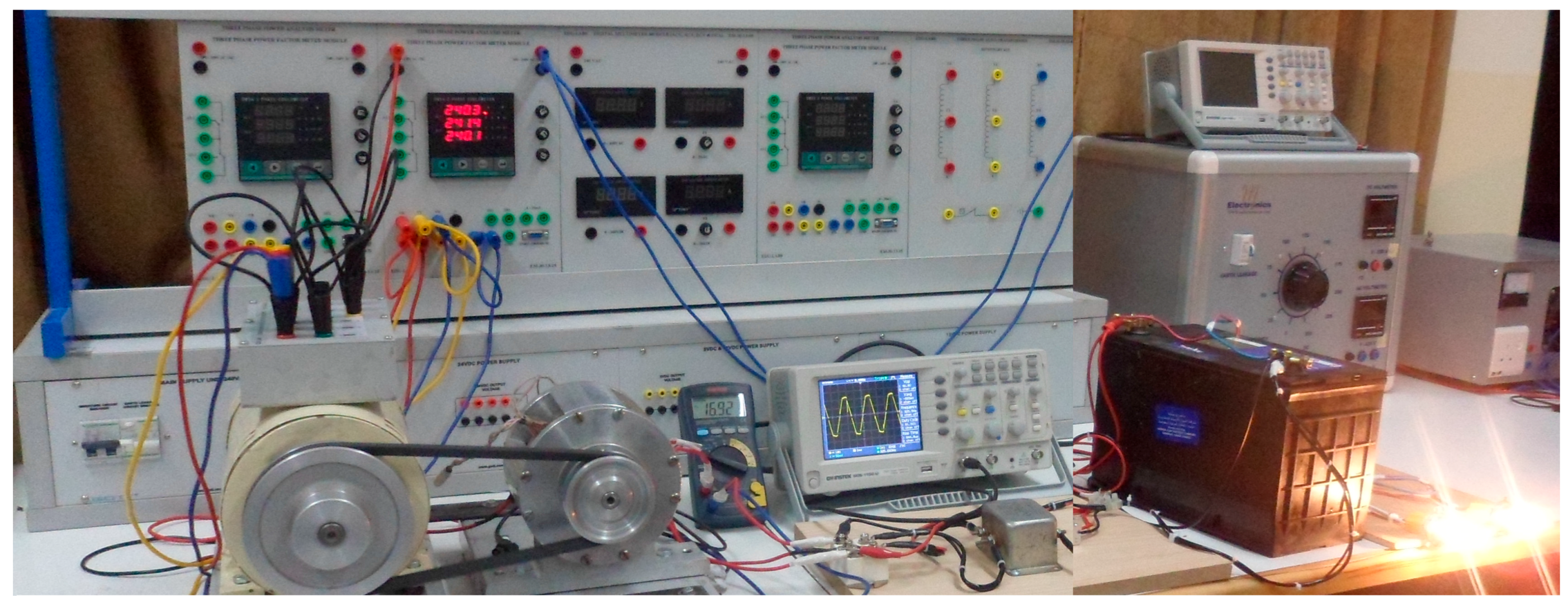
8.2. Load Tests
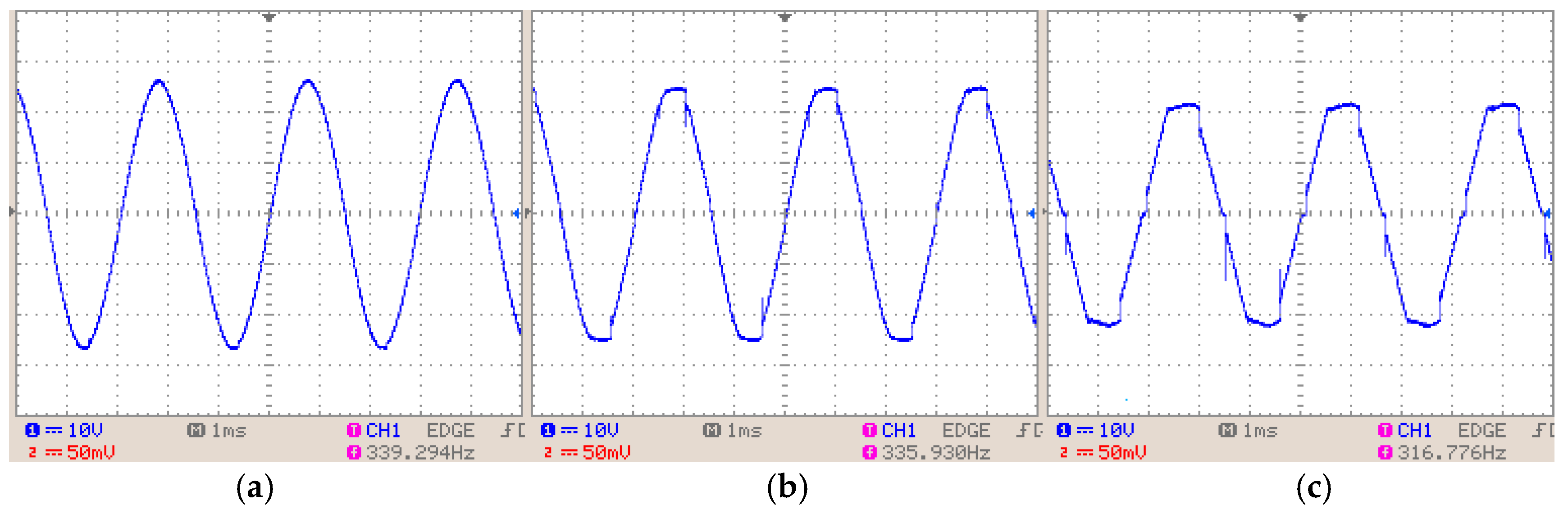
In this section, the AFPMA and the AC/DC converter are tested under load conditions as shown in Figure 26. First set of results is obtained when the system is connected to the battery only. The second set of results is obtained when the system is connected to the battery and a single head lamp. The third set of results is obtained when the system is connected battery and two head lamps. Results obtained for the three loading conditions as compared to the no load condition are summarized in Table 5. It is shown from the results that the controller was successful in maintaining almost a constant output voltage close to 14 V DC with an average decrease of 2.7% for a 30% increase in load current and 6.6% decrease in average output voltage for 60% increase in load current. Also, when analyzing the alternator’s output waveforms, it is noticed that the line–line voltage gets more distorted as the controlled converter is processed to provide more charging current while the alternator running is also decreased as can be shown in Figure 27.
9. Conclusions and Future Recommendations
This paper exhibited the design methodology and optimization of AFPMA having ACSTR configuration and its integration with three phase fully controlled AC/DC converter as part of the onboard battery charging system for use in automobile applications. The necessary sizing equations were developed, and optimization of the machine was performed based on parametric analysis. The number of winding turns, hence machine design speed, were optimized against the machine efficiency. Analytical results showed that the AFPMA having four turns per coil per phase is suitable to run at nearly 4800 rpm to achieve an power output of 1.2 kW at rated line voltage of 17 and rated current of 40 A at an expected efficiency of 94%. The AFPMA was modeled using MATLAB/Simulink and the results obtained were close to analytical solutions. The response of the AFPMA while operating with a three-phase controlled rectifier using six IGBT bridge is modeled and experimentally tested, forming the basis for the design of a closed-loop controller to regulate the output voltage. The experimental performance of the closed-loop system is examined and evaluated. A custom design comparator circuit was developed to produce the necessary pulses for Arduino Uno and was capable of dealing with asymmetrical output voltage conditions from the AFPMA. The Arduino was used as a controller that generates the required pulses for triggering the IGBTs sequentially in a timely manner. The Arduino custom code enabled the production of a regulated DC output voltage across the battery via controlling the firing angle of the IGBT model in proportion to the amount of voltage difference between the battery voltage preset value and the measured value. The overall system was experimentally tested under partial loading conditions and results obtained showed the validity of the analytical as well as the simulation results within acceptable level. Experimental results demonstrated that the closed-loop controller was successful in regulating the output voltage close to 14 V DC while the alternator was operating in the range of the rated speed. Measurements showed a 2.7% decrease in average output voltage for a 30% increase in load current. It is worth mentioning that some amount of the voltage drop can be attributed to the drop in the alternator speed (approximately 2.9%) due to the increased load torque on the electrical motor that is driving the alternator. For accurate evaluation and assessment of the system performance, it is recommended to use alternative prime movers that can provide constant speed during load variations. Further investigations of the output power for the system using the controlled rectifier are also required at higher speed operation. Moreover, it was noticed that during the loading tests, that the machine voltage/speed constant () tends to change under high current loading. This can be explained by the flux weakening that occurs in the middle of the air gap due to armature reaction. More experimental results need to be conducted to determine the exact relationship and to account for this change in the MATLAB/Simulink model. Also, preliminary laboratory tests showed a rise of 50 °C in the temperature of the stator winding above ambient temperature of 25 °C when the full load current of 40 A is drawn from the machine for a period of two hours without using integral fan. It is anticipated that the stator winding temperature may rise in the range of 100–130 °C when the AFPMA is tested in an engine compartment due to the elevated ambient temperature. This in turn may cause a temperature increase in the nearby magnets which may lead to demagnetization of the PMs. Therefore, the cooling aspect of the AFPMA needs to be considered in order to minimize the temperature rise by using an integral fan on the shaft or other methods of forced ventilation. More experimental tests are required to test the system under several full loading conditions. Using alternative grades of NdFeB can be decided once the machine is tested on-board of the vehicle at several loading conditions. In general, the preliminary results showed the potential capabilities of the AFPMA for meeting increasing power demands in automotive applications. In addition, a scaled up system can be also made in the future to satisfy higher power ratings of automobiles.
Acknowledgments
The author acknowledges that this research is funded by the Deanship of Research and Graduate Studies at Zarqa University/Jordan. The author also would like to extend his gratitude to the laboratory supervisor Eng. Mohammad Mosleh as well as to Eng. Basil Al Jamal and Eng. Yazan Shihab for their help in conducting the experimental work at the electrical engineering department of Zarqa University.
Conflicts of Interest
The author declares no conflict of interest.
Nomenclature
| Air gap/magnet interface area | |
| Winding cross sectional area | |
| Air gap magnetic flux density | |
| Magnetic remanence | |
| Coefficient drag for turbulent flow | |
| Coil mean path length | |
| Wire diameter | |
| Induced voltage in a conductor | |
| Per phase internal generated voltage | |
| Electrical frequency of the voltage | |
| Magnetic coercive force | |
| Armature current | |
| d-axis current | |
| q-axis current | |
| Machine geometrical constant | |
| Machine magnetic constant | |
| Conductor length | |
| d-axis inductance | |
| Per phase leakage inductance | |
| Magnet axial length | |
| Total magnet air gap length | |
| q-axis inductance | |
| Winding Inductance | |
| Magnetization inductance | |
| Machine voltage/speed constant | |
| Mechanical speed | |
| Minim acceptable speed of the AFPMA | |
| Number of rotating discs | |
| Number of winding turns | |
| Rotor number of poles | |
| Copper losses | |
| Wire packing factor | |
| Internal power factor for the machine | |
| Machine output power | |
| Windage losses | |
| Maximum windage losses | |
| Saving in the windage losses | |
| Average radius of conductor | |
| Centre point of the PM disc | |
| Reynolds number | |
| Reluctance of the path of the magnetising flux | |
| Inner radius of the coil | |
| Outer radius of the coil | |
| Shaft radius | |
| Winding resistance | |
| Electromagnetic torque | |
| Linear velocity vector | |
| d-axis voltage | |
| Rectifier average output voltage | |
| RMS line voltage | |
| Minim line-line RMS voltage | |
| Voltage regulation of the machine | |
| q-axis voltage | |
| Full load phase voltage | |
| No load phase voltage | |
| Total winding length | |
| Air gap half-distance | |
| Winding reactance | |
| Rectifier firing angle | |
| Temperature coefficient for | |
| Temperature coefficient for | |
| Machine power angel | |
| Efficiency of the machine | |
| Peak flux reaching the stator windings | |
| Coefficient of viscosity of the air | |
| Specific density of the surrounding air | |
| Mechanical angular velocity |
Appendix A. Derivation of the Sizing Equations for the AFPMA
The magnetic flux density in the air gap between the two PM rotors (assuming circular PMs) is calculated as [33,34,35,36]:
where R is center point of the PM disc which can be determined as:
Hence, the induced voltage in the conductors is given by:
Since is perpendicular to , the magnitude of the induced voltage reduces to:
The tangential velocity of the conductor can be represented in terms of angular velocity as:
where is the average radius of the conductor (m), also called the magnet centerline and can be found as:
The angular velocity can be expressed in terms of mechanical speed of the rotor as:
The average effective length of the winding conductor, can be calculated as
Substituting (A7) into (A5) and then into (A4)
For number of turns per phase and for number of poles , substituting (A6) and (A8) into (A9) can be represented as:
For three phase stator, the line-line rms induced voltage can be expressed as:
Hence, the number of turns can be found as:
The above equation can be reduced to:
where , and are the machine magnetic constant and geometric constant, respectively.
The frequency of the generated voltage is determined by:
The AFPMA under consideration has a non-salient rotor topography. Also the stator has an air-cored structure which enables sinusoidal flux distribution. Hence, the inductance of the machine can be calculated as [37]:
The per phase leakage inductance can be calculated as:
where is the coil mean path length which can be determined based on the geometry of the coil as:
The winding resistance can be calculated as:
where is the total winding length, is the winding cross sectional area, is the wire diameter, and is the wire packing factor and it can be defined in the range between 1.2 and 1.3 depending on the wire diameter. By performing magnetic circuit analysis, the reluctance of the PM and the coil can be calculated, hence the magnetizing inductance can be determined as:
where is total reluctance of the path of the magnetising flux and can be calculated as:
where is the air gap (axial length) half-distance, is the total magnet air gap length, and is the air gap/magnet interface area. The per-phase synchronous reactance of the stator windings are calculated as:
Appendix B. Simulink Mathematical Model of the AFPMA in Rotor Reference Frame (dq-Axis)
The dq-axis currents can be described as
The coreless (ironless) stator of the AFPMA implies that the stator inductance as referred to the dq-axis does not vary with rotor position, which makes = = . Hence the electromagnetic torque of the machine can be expressed as
References
- Ivankovic, R.; Cros, J.; Kakhki, M.T.; Martins, C.A.; Viarouge, P. Power Electronic Solutions to Improve the Performance of Lundell Automotive Alternators. In New Advances in Vehicular Technology and Automotive Engineering; InTech: London, UK, 2012; Chapter 6. [Google Scholar] [CrossRef]
- Whaley, D.M.; Soong, W.L.; Ertugrul, N. Extracting More Power from the Lundell Car Alternator. In Proceedings of the Australasian Universities Power Engineering Conference (AUPEC 2004), Brisbane, Australia, 26–29 September 2004. [Google Scholar]
- Tang, S.C.; Otten, D.M.; Keim, T.A.; Perreault, D.J. Design and Evaluation of a 42-V Automotive Alternator with Integrated Switched-Mode Rectifier. IEEE Trans. Energy Convers. 2010, 25, 983–992. [Google Scholar] [CrossRef]
- Perreault, D.J.; Caliskan, V. Automotive Power Generation and Control. IEEE Trans. Power Electron. 2004, 19, 618–630. [Google Scholar] [CrossRef]
- Wang, Q.; Niu, S.; Yang, L. Design Optimization and Comparative Study of Novel Dual-PM Excited Machines. IEEE Trans. Ind. Electron. 2017, 64, 9924–9933. [Google Scholar] [CrossRef]
- Pop, A.C.; Gyselinck, J.J.; Pinto, D.E.; Vintiloiu, I. Optimization of Low-Power Brushless PM-Machines for Automotive Applications with Focus on High-Volume Mass Production. IEEE Trans. Ind. Electron. 2017, 64, 9767–9775. [Google Scholar] [CrossRef]
- Chen, A.; Nilssen, R.; Nysveen, A. Performance Comparisons among Radial-Flux, Multistage Axial-Flux, and Three-Phase Transverse-Flux PM Machines for Downhole Applications. IEEE Trans. Ind. Appl. 2010, 46, 779–789. [Google Scholar] [CrossRef]
- Cavagnino, A.; Lazzari, M.; Profumo, F.; Tenconi, A. A comparison between the axial flux and the radial flux structures for PM synchronous motors. IEEE Trans. Ind. Appl. 2002, 38, 1517–1524. [Google Scholar] [CrossRef]
- Ishikawa, T.; Amada, S.; Segawa, K.; Kurita, N. Proposal of a Radial- and Axial-Flux Permanent-Magnet Synchronous Generator. IEEE Trans. Magn. 2017, 53. [Google Scholar] [CrossRef]
- Pop, A.A.; Jurca, F.; Oprea, C.; Chirca, M.; Breban, S.; Radulescu, M.M. Axial-flux vs. radial-flux permanent-magnet synchronous generators for micro-wind turbine application. In Proceedings of the 15th Conference on Power Electronics and Applications (EPE’13 ECCE Europe), Lille, France, 3–5 September 2013. [Google Scholar]
- Kahourzade, S.; Mahmoudi, A.; Ping, H.W.; Uddin, M.N. A Comprehensive Review of Axial-Flux Permanent-Magnet Machines. Can. J. Electr. Comput. Eng. 2014, 37, 19–33. [Google Scholar] [CrossRef]
- Nguyen, T.D.; Tseng, K.J.; Zhang, S.; Nguyen, H.T. A Novel Axial Flux Permanent-Magnet Machine for Flywheel Energy Storage System: Design and Analysis. IEEE Trans. Ind. Electron. 2010, 58, 3784–3794. [Google Scholar] [CrossRef]
- Chan, T.F.; Lai, L.L. An axial-flux permanent-magnet synchronous generator for a direct-coupled wind-turbine system. IEEE Trans. Energy Convers. 2007, 22, 86–94. [Google Scholar] [CrossRef]
- El-Hasan, T.S.; Luk, P.C.; Bhinder, F.S.; Ebaid, M.S. Modular design of high-speed permanent-magnet axial-flux generators. IEEE Trans. Magn. 2000, 36 Pt 1, 3558–3561. [Google Scholar] [CrossRef]
- El-Hasan, T.S.; Luk, P.C. Magnet topology optimization to reduce harmonics in high-speed axial flux Generators. IEEE Trans. Magn. 2003, 39 Pt 2, 3340–3342. [Google Scholar] [CrossRef]
- Fei, W.; Luk, P.C.K.; El-Hasan, T.S. Rotor Integrity Design for a High-Speed Modular Air-Cored Axial-Flux Permanent-Magnet Generator. IEEE Trans. Ind. Electron. 2011, 58, 3848–3858. [Google Scholar] [CrossRef] [Green Version]
- Bumby, J.R.; Martin, R. Axial-Flux Permanent-Magnet Air-Cored Generator for Small-Scale Wind Turbines. IEE Proc. Electr. Power Appl. 2005, 152, 1065–1075. [Google Scholar] [CrossRef]
- Ferreira, Â.P.; Costa, A.F. Direct Driven Axial Flux Permanent Magnet Generator for Small-Scale Wind Power Applications. In Proceedings of the International Conference on Renewable Energies and Power Quality (ICREPQ’11), Las Palmas de Gran Canaria, Spain, 13–15 April 2010. [Google Scholar]
- El-Hasan, T.S. Development of axial flux permanent magnet generator for direct driven micro wind turbine. In Proceedings of the IEEE International Conference on Renewable Energy Research and Applications (ICRERA 2016), Birmingham, UK, 20–23 November 2016. [Google Scholar]
- Di Gerlando, A.; Foglia, G.M.; Iacchetti, M.F.; Perini, R. Sizing comparison of axial flux PM motors, for automotive application. In Proceedings of the 2014 International Conference on Electrical Machines (ICEM), Berlin, Germany, 2–5 September 2014. [Google Scholar]
- Bastiaens, K.; Jansen, J.W.; Jumayev, S.; Lomonova, E.A. Design of an axial-flux permanent magnet machine for an in-wheel direct drive application. In Proceedings of the 2017 IEEE International Electric Machines and Drives Conference (IEMDC), Miami, FL, USA, 21–24 May 2017. [Google Scholar]
- Javadi, S.; Mirsalim, M. Design and Analysis of 42-V Coreless Axial-Flux Permanent-Magnet Generators for Automotive Applications. IEEE Trans. Magn. 2010, 46, 1015–1023. [Google Scholar] [CrossRef]
- Javadi, S.; Mirsalim, M. A Coreless Axial-Flux Permanent-Magnet Generator for Automotive Applications. IEEE Trans. Magn. 2008, 44, 4591–4598. [Google Scholar] [CrossRef]
- China YY Magnetics. Available online: http://www.smi-mag.com/Neodymiummagnets.html?gclid=EAIaIQobChMIhZ2C5qa32AIVJyjTCh0OUAYgEAAYASAAEgI7-_D_BwE (accessed on 6 January 2018).
- Deeb, R.; Janda, M.; Makki, Z. Design of Cooling System of Permanent Magnet Servo Motor. In Proceedings of the 14th International Scientific Conference Electric Power Engineering 2013; VSB—Technical University of Ostrava: Ostrava, Czech Republic, 2013; pp. 205–209. ISBN 978-80-248-2988-3. [Google Scholar]
- E-Magnets UK Company. Available online: http://e-magnetsuk.com/neodymium_magnets/temperature_ratings.aspx (accessed on 6 January 2018).
- MathWorks. Available online: https://www.mathworks.com/help/physmod/sps/powersys/ref/permanentmagnetsynchronousmachine.html (accessed on 5 March 2017).
- Krah, J.O.; Holtz, J. High-Performance Current Regulation and Efficient PWM Implementation for Low Inductance Servo Motors. IEEE Trans. Ind. Appl. 1999, 35, 1039–1049. [Google Scholar] [CrossRef]
- Krahenbuhl, D.; Zwyssig, C.; Kolar, J.W. Half-Controlled Boost Rectifier for Low-Power High-Speed Permanent-Magnet Generators. IEEE Trans. Ind. Electron. 2011, 58, 5066–5075. [Google Scholar] [CrossRef]
- Bai, H. Study of PWM Rectifier/Inverter for a High Speed Generator. In Proceedings of the Power and Energy Engineering Conference, Chengdu, China, 28–31 March 2010. [Google Scholar]
- El-Hasan, T.; Elnasser, E.M. Development of a Low Cost Sensored Control for High-Speed Axial Flux Permanent Magnet Machines. J. Innov. Syst. Des. Eng. 2014, 5, 7–16. [Google Scholar]
- Hart, D.W. Power Electronics, 1st ed.; McGraw-Hill Education: New York, NY, USA, 2010; ISBN 10 0073380679. [Google Scholar]
- El-Hasan, T.S. Modelling, Simulation and Experimentation of PM Spring. Int. Rev. Model. Simul. 2016, 9, 56–63. [Google Scholar] [CrossRef]
- El-Hasan, T.S. Application of Permanent Magnets in Suspension and Recoil Buffer Systems. J. Innov. Syst. Des. Eng. 2015, 6, 1–14. [Google Scholar]
- Camacho, J.M.; Sosa, V. Alternative method to calculate the magnetic field of permanent magnets with azimuthal symmetry. Rev. Mex. Fis. E 2013, 59, 8–17. [Google Scholar]
- Babic, S.I. Improvement in the Analytical Calculation of the Magnetic Field Produced by Permanent Magnets ring. Prog. Electromagn. Res. C 2008, 5, 71–82. [Google Scholar]
- El-Hasan, T.S. Inductance Determination for Air-Cored Permanent Magnet Axial Flux Machine. In Proceedings of the Global Summit on Electronics and Electrical Engineering, Valencia, Spain, 3–5 November 2015. [Google Scholar]
Figure 1.
AFPMA under consideration: (a) 3D exploded view of ACSTR; (b) assembled AFPMA.
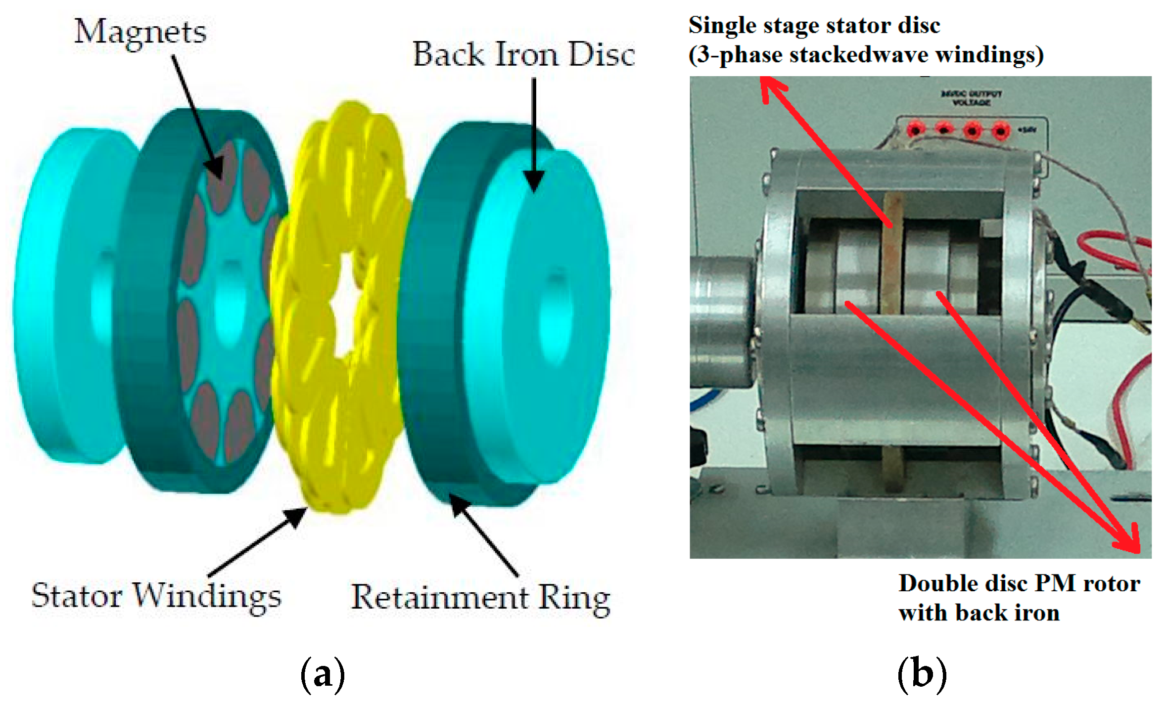
Figure 2.
AFPMA rotor and stator main parameters.

Figure 3.
Normalized energy product vs. different grades of NdFeB at their corresponding maximum operating temperatures: (a) calculated at 20 °C; (b) calculated at 80 °C. Based on available information from China YY Magnetics (Zhejiang, China) [24].
Figure 3.
Normalized energy product vs. different grades of NdFeB at their corresponding maximum operating temperatures: (a) calculated at 20 °C; (b) calculated at 80 °C. Based on available information from China YY Magnetics (Zhejiang, China) [24].
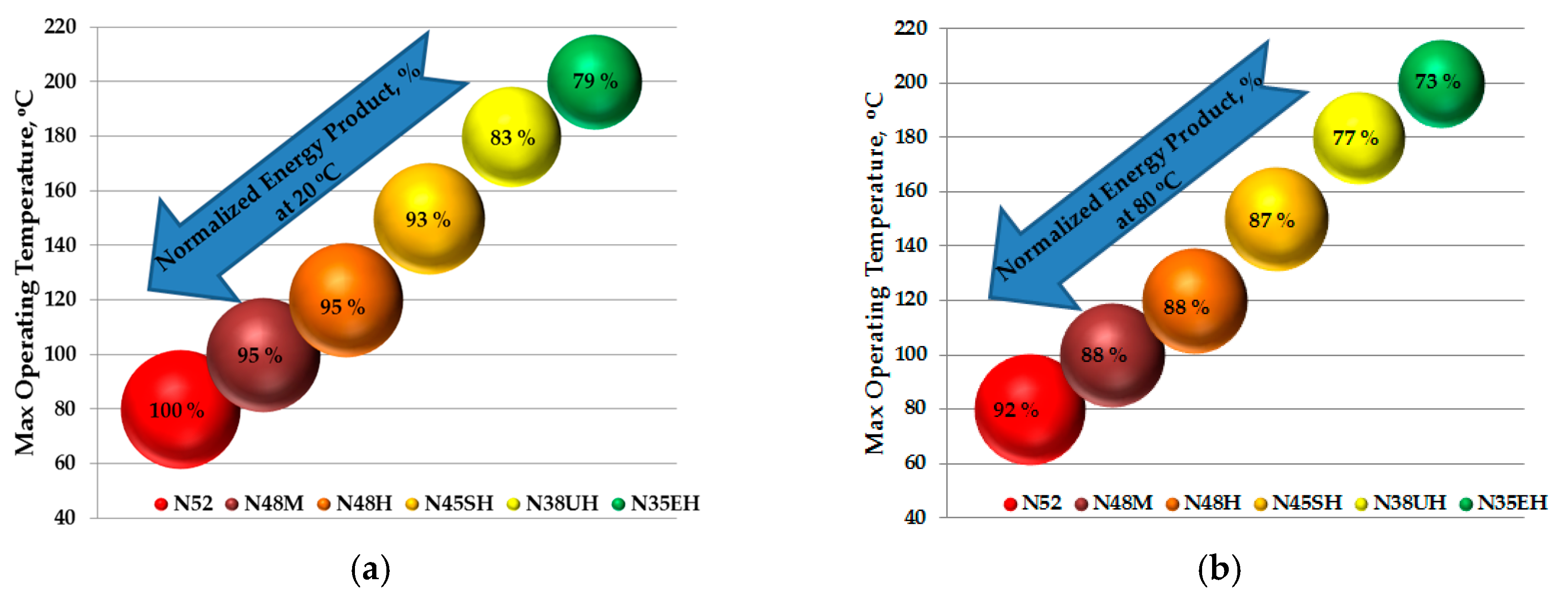
Figure 4.
Degrading of the normalized energy product as a function of the temperature increase for several grades of NdFeB. Based on available information from e-magnets UK (Hertfordshire, UK) [26].
Figure 4.
Degrading of the normalized energy product as a function of the temperature increase for several grades of NdFeB. Based on available information from e-magnets UK (Hertfordshire, UK) [26].

Figure 5.
Optimization results for the AFPMA: (a) Machine efficiency and the internal power factor vs. number of turns; (b) Saving in windage losses, voltage regulation, and rotational speed vs. number of turns.
Figure 5.
Optimization results for the AFPMA: (a) Machine efficiency and the internal power factor vs. number of turns; (b) Saving in windage losses, voltage regulation, and rotational speed vs. number of turns.

Figure 6.
AFPMA MATLAB/Simulink model and parameter configuration.
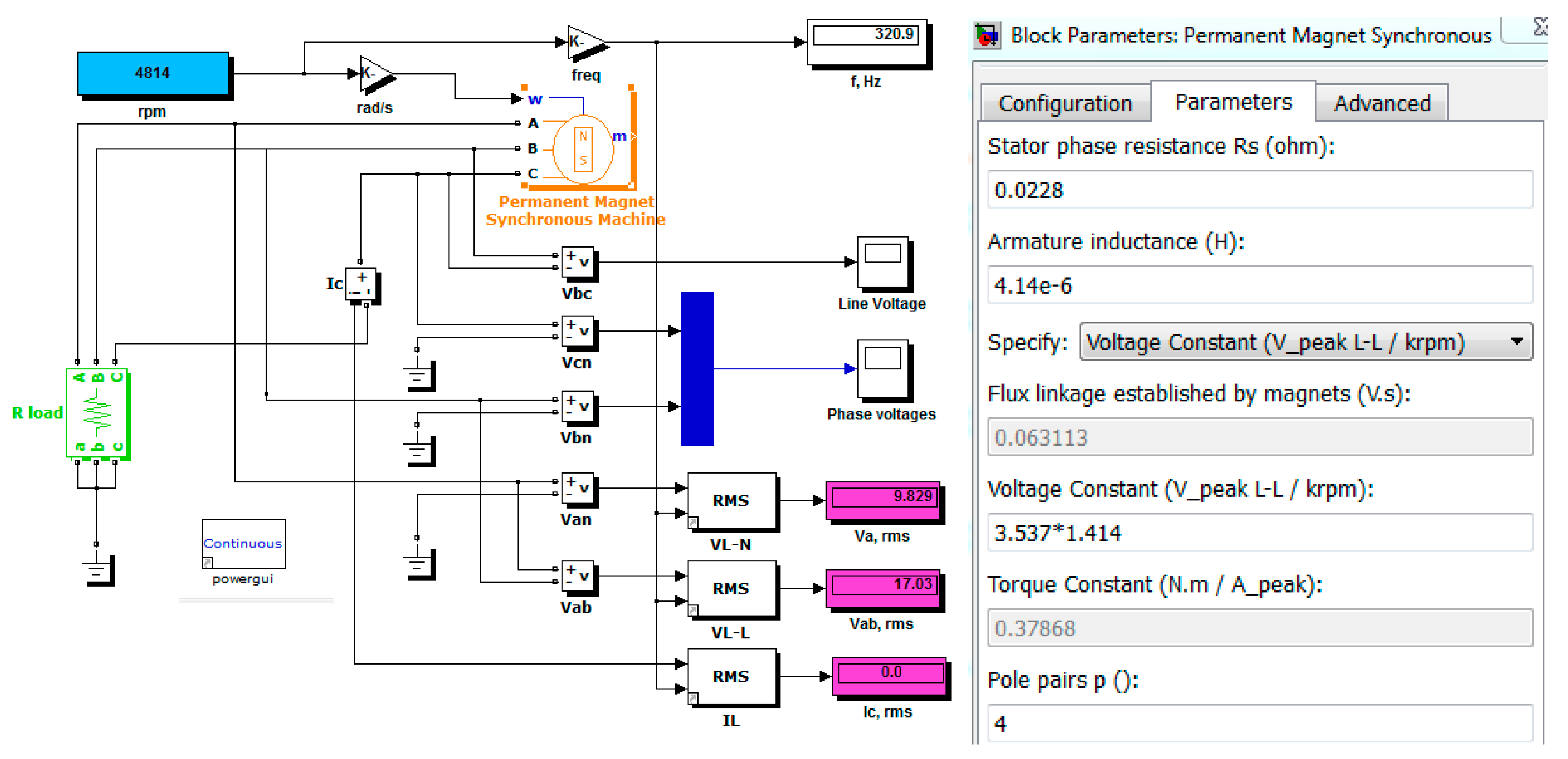
Figure 7.
AFPMA equivalent circuit: (a) d-axis model; (b) q-axis model.

Figure 8.
Expected AFPMA line–line rms voltages at no load for several operating speeds.
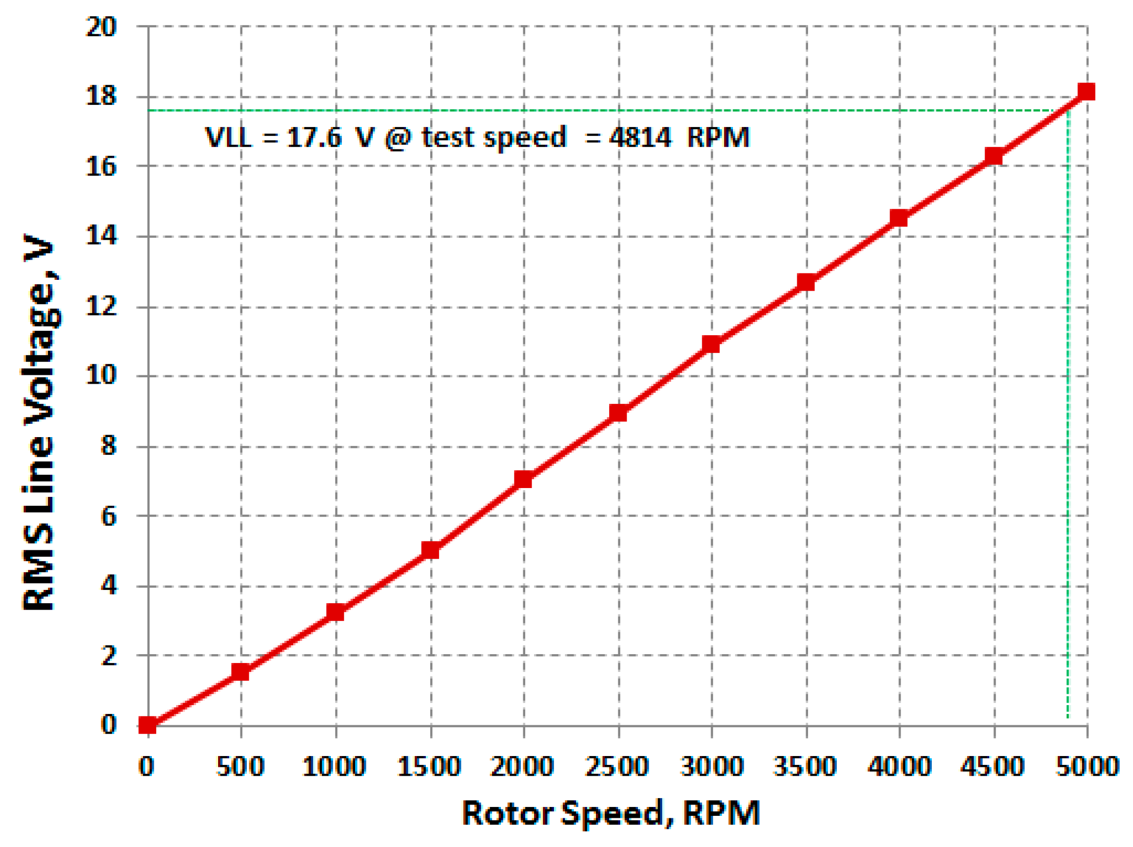
Figure 9.
Proposed automotive electrical powering system using AFPMA harnessed with fully controlled AC/DC rectifier.
Figure 9.
Proposed automotive electrical powering system using AFPMA harnessed with fully controlled AC/DC rectifier.

Figure 10.
Voltage measurement and comparator circuit.
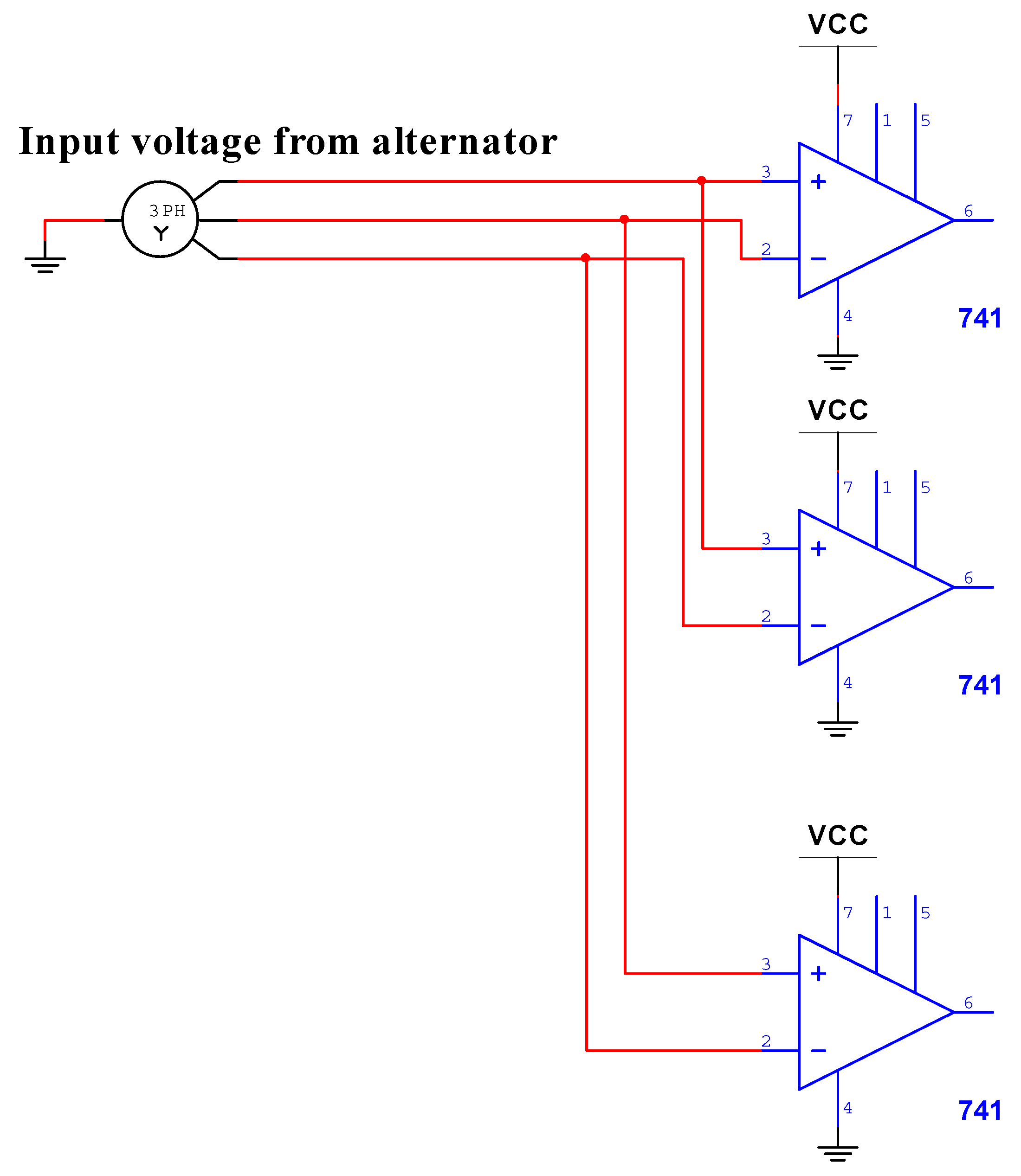
Figure 11.
IGBT switching sequence for controlled rectifier operation.
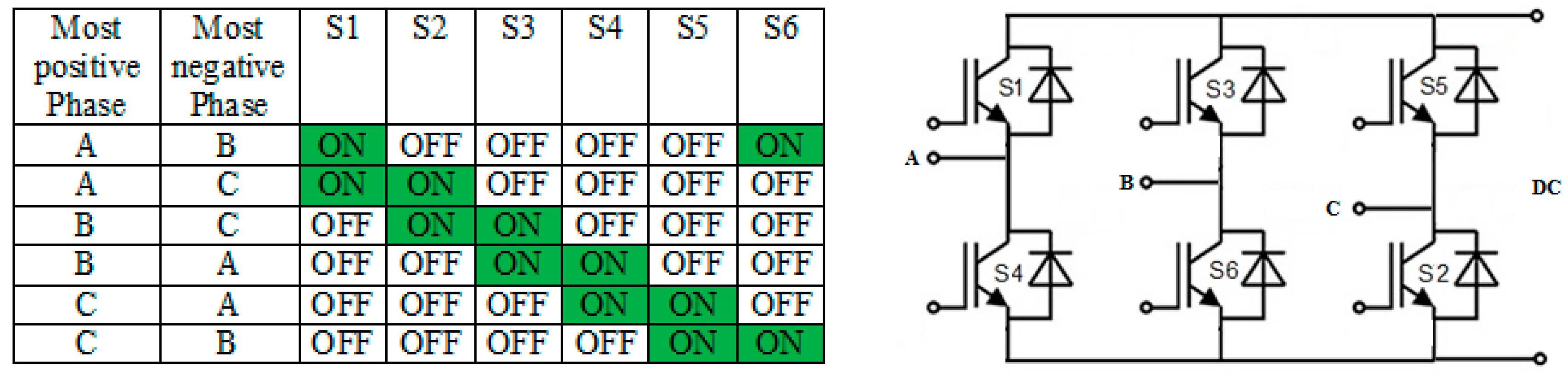
Figure 12.
Complete system simulation using MATLAB/Simulink model.
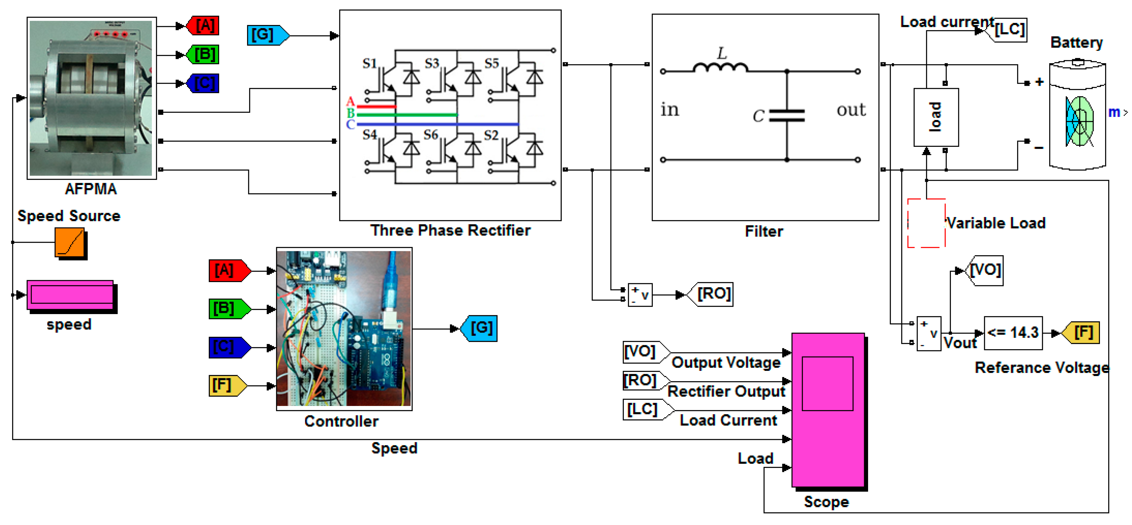
Figure 13.
Algorithm used to enable the controller for simulation purposes.
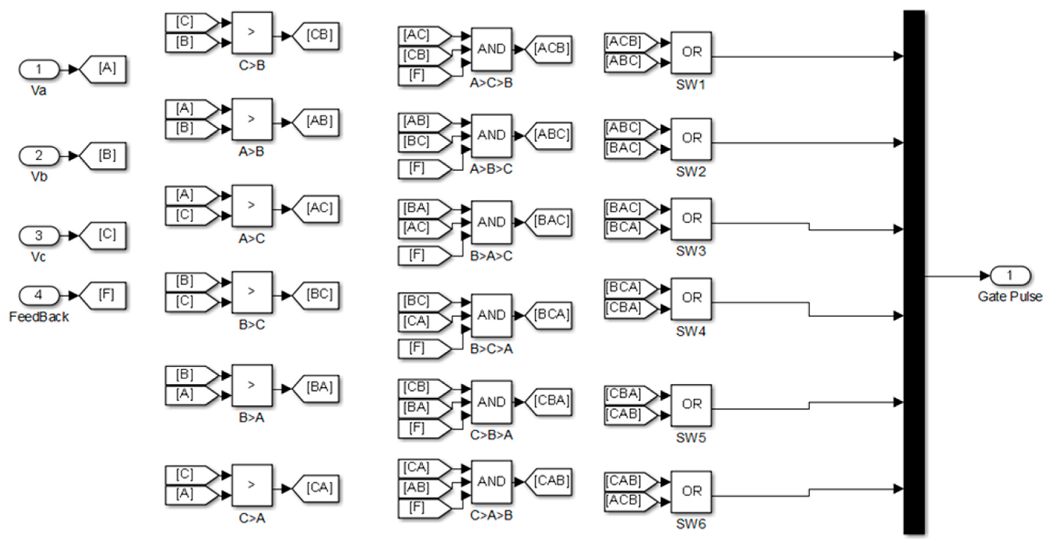
Figure 14.
Controller output pulses (zero–one).

Figure 15.
Simulation results for open circuit rectifier output voltage at 5000 rpm at firing angle α = 0.
Figure 15.
Simulation results for open circuit rectifier output voltage at 5000 rpm at firing angle α = 0.

Figure 16.
Simulation results for constant electrical load and variable AFPMA speed.

Figure 17.
Simulation results for constant speed and variable electrical load.

Figure 18.
Simulation results for variable speed and variable electrical load.

Figure 19.
Experimental test rig; (1) Three-phase driving motor, (2) AFPMA, (3) controller circuit, (4) IGBT six-pack module CM100TF-12H, (5) three-phase power supply, (6) dummy resistive load, (3a) comparator circuit, (3b) Arduino Uno, (3c) IGBT gate driver circuit.
Figure 19.
Experimental test rig; (1) Three-phase driving motor, (2) AFPMA, (3) controller circuit, (4) IGBT six-pack module CM100TF-12H, (5) three-phase power supply, (6) dummy resistive load, (3a) comparator circuit, (3b) Arduino Uno, (3c) IGBT gate driver circuit.

Figure 20.
AFPMA no load voltage (line-neutral) experimental results vs. simulation results at .
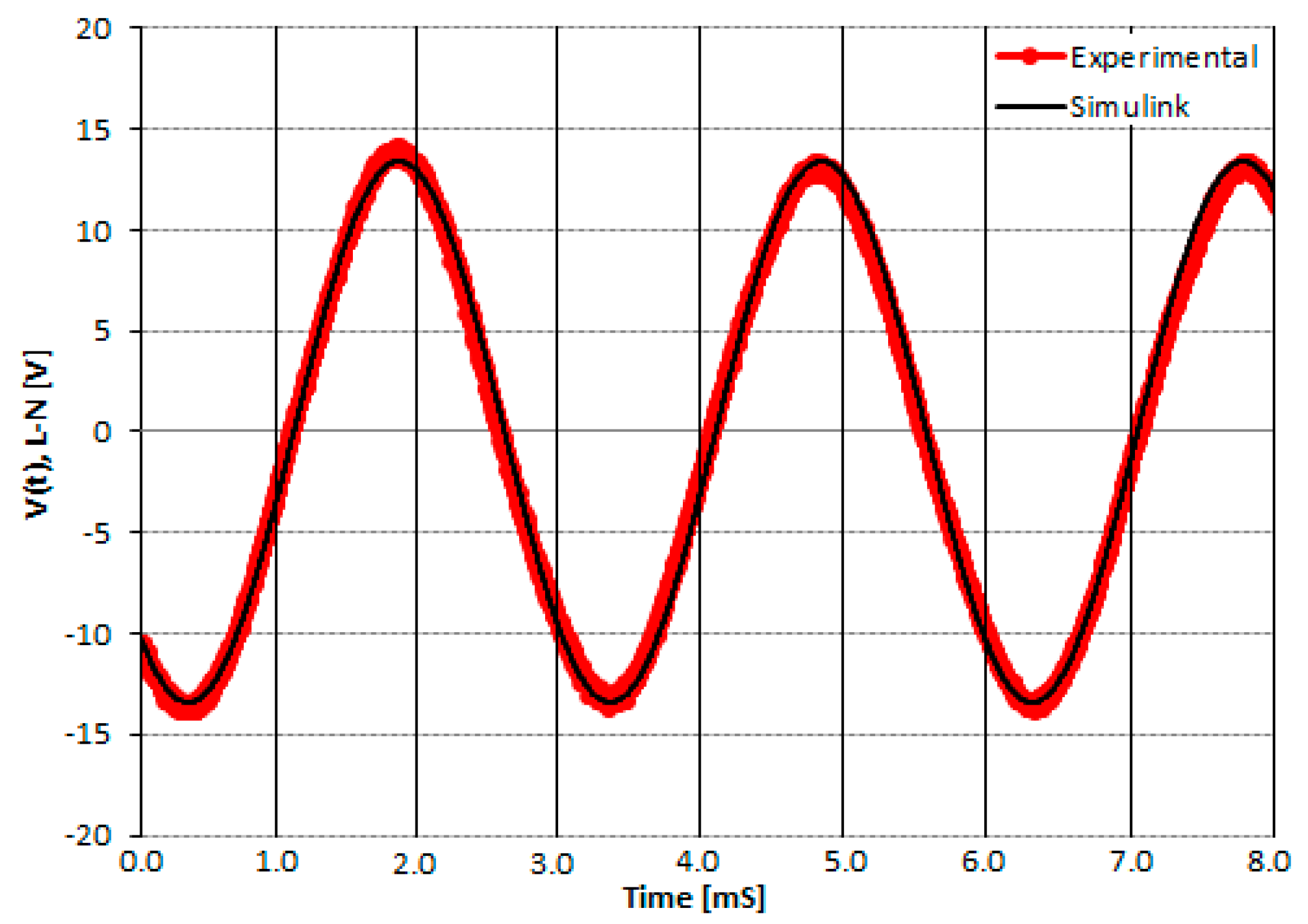
Figure 21.
AFPMA no load three-phase line-neutral voltages tested at .
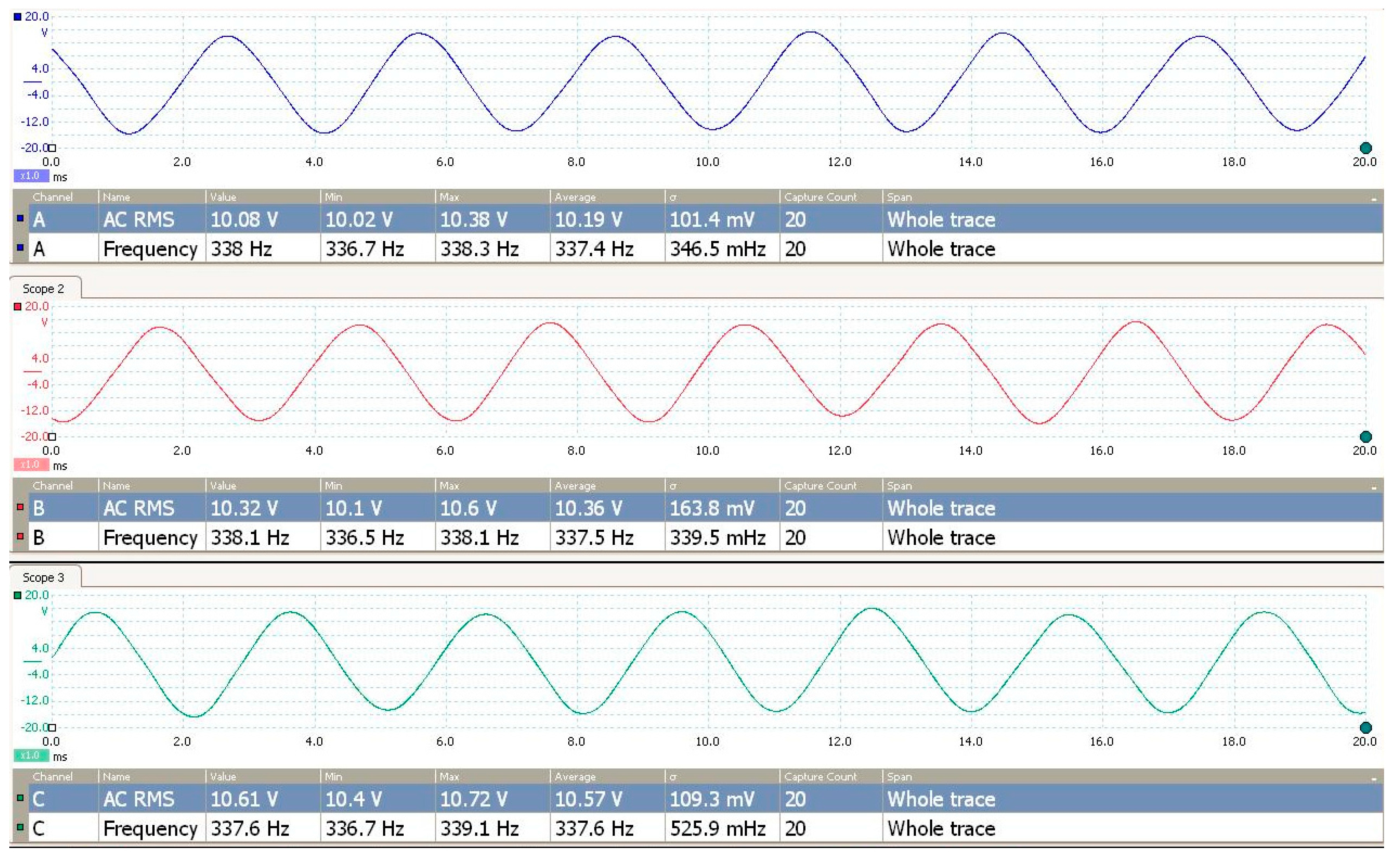
Figure 22.
AFPMA phase voltage THD % experimental result at .
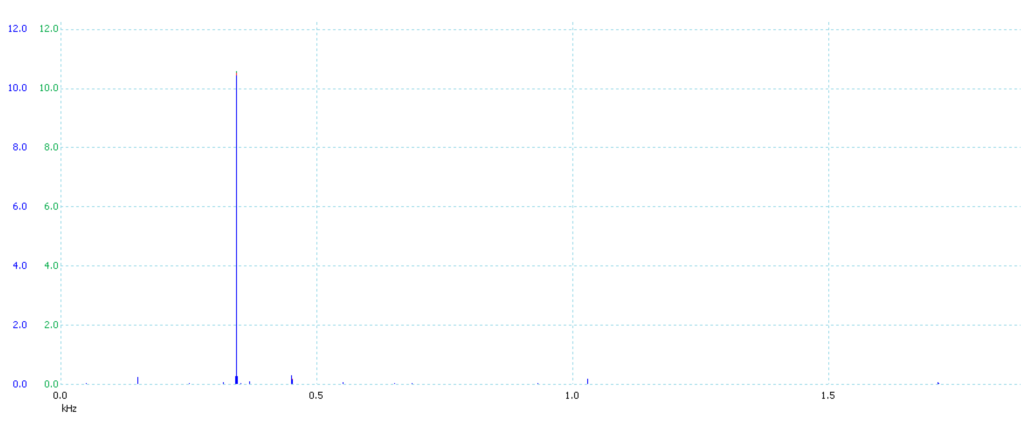
Figure 23.
Rectifier output voltage at zero firing angle at .
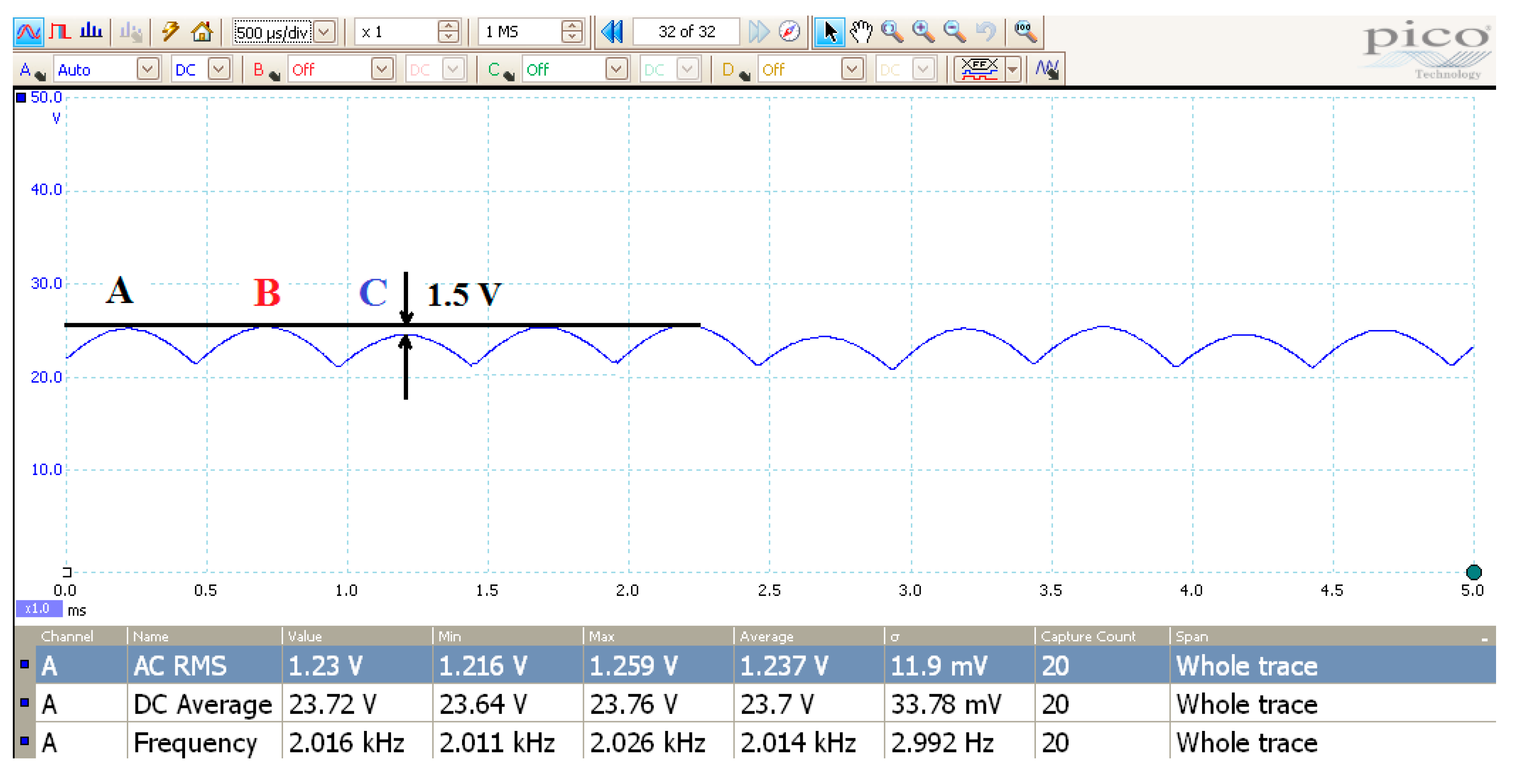
Figure 24.
Phase C and A with adaptive pulse generated from the comparator at .
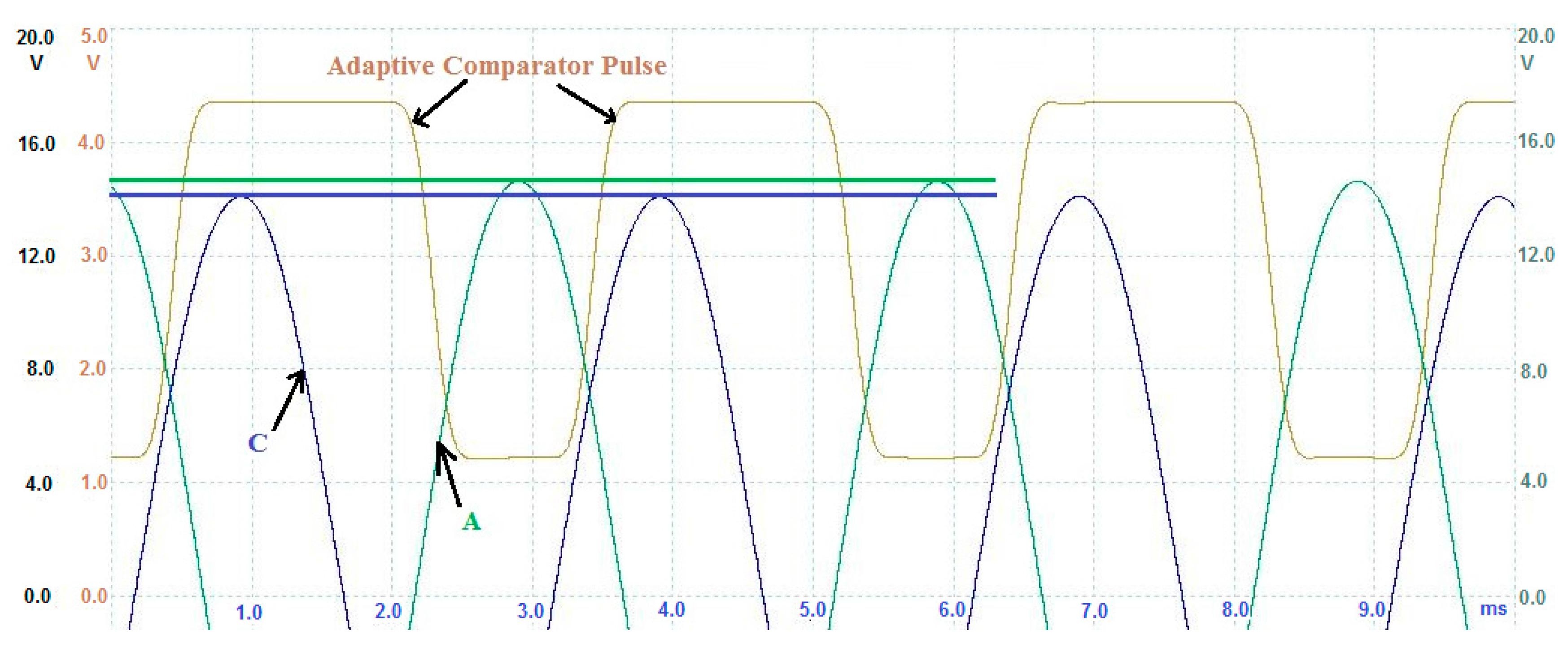
Figure 25.
Arduino pulses with appropriate pulse widths to allow for adaptive control of AC/DC converter.
Figure 25.
Arduino pulses with appropriate pulse widths to allow for adaptive control of AC/DC converter.
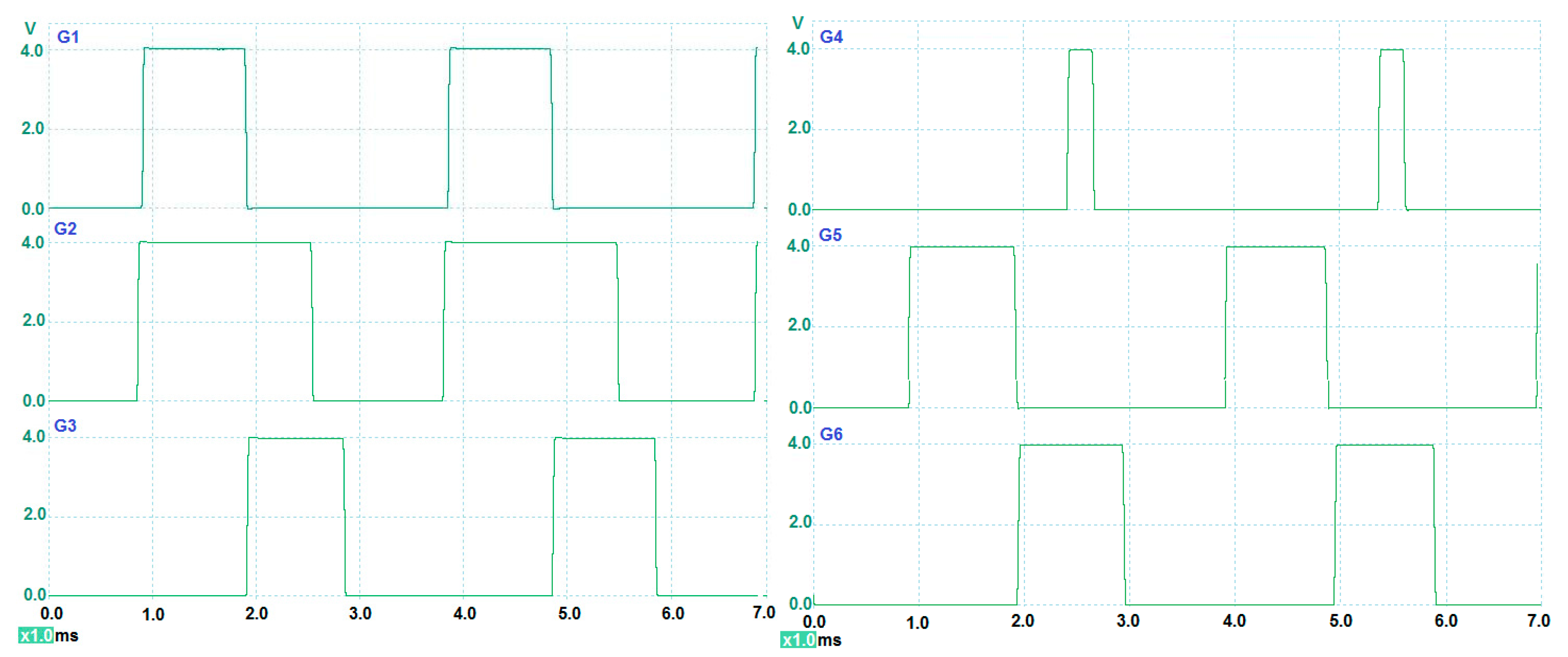
Figure 26.
Testing of AFPMA and AC/DC converter under charging process (battery and load connected).
Figure 26.
Testing of AFPMA and AC/DC converter under charging process (battery and load connected).

Figure 27.
Distorted line–line output voltages due to increased load current; (a) without rectifier and no load at 5085 rpm; (b) with rectifier and no load at 5032 rpm; (c) with rectifier and charging current of 11 A at 4740 rpm.
Figure 27.
Distorted line–line output voltages due to increased load current; (a) without rectifier and no load at 5085 rpm; (b) with rectifier and no load at 5032 rpm; (c) with rectifier and charging current of 11 A at 4740 rpm.


Table 1.
AFPMA Requirements.
| AFPMA Set Parameters | Value | Unit |
|---|---|---|
| RMS line–line voltage | 17 | V |
| Rated current | 40 | A |
| Rated speed | 5000 | RPM |
| Rated power @ rated speed | 1.2 | kVA |
Table 2.
AFPMA Set Parameters.
| AFPMA Set Parameters | Value | Unit |
|---|---|---|
| Desired line–line RMS output voltage | 17.6 | V |
| Number of phases (star connected) | 3 | - |
| Air gap half-distance, | 10 | mm |
| Number of poles, | 8 | - |
| Axial thickness of PM, | 17 | mm |
| Inner radius of PM, | 27 | mm |
| Outer radius of PM, | 48 | mm |
| Remanence for NdFeB Grade 52, | 1.45 | T |
| Wire diameter, | 2.2 | mm |
Table 3.
AFPMA Calculated Parameters.
| AFPMA Calculated Parameters | Value | Unit |
|---|---|---|
| Number of winding turns per pole per phase, | 4 | - |
| Winding resistance per phase, | 22.8 | mΩ |
| Winding inductance per phase, | 4.14 | µH |
| Design speed, | 4814 | RPM |
| No load machine voltage/speed constant, | 3.537 × 10⁻³ | V/RPM |
| Generated frequency, | 320 | Hz |
| Air gap flux density, | 0.546 | T |
| Voltage regulation, % | 10.3 | - |
| Machine internal power factor (cos φ), | 0.94 | - |
| Machine power angle, δ | 2 | Deg |
| Efficiency, (%) | 94 | - |
Table 4.
AFPMA and rectifier output voltages at no load vs. speed at .
| AFPMA Speed, (RPM) | (V) | (V) | (V) |
|---|---|---|---|
| Design speed = 4814 | 17.6 | 24.89 | 23.7 |
| Minimum speed = 2997 | 10.6 | 14.9 | 14.3 |
| Maximum speed 5000 | 18.29 | 25.8 | 24.7 |
Table 5.
AFPMA and AC/DC converter under loading conditions vs. no load condition.
| Test Condition | Speed | |||
|---|---|---|---|---|
| (RPM) | (V) | (V) | (A) | |
| No load (rectifier only) | 5032 | 18.41 | 24.15 | 0 |
| Battery only | 5020 | 18.01 | 14.53 | 2.85 |
| Battery and one head lamp | 4876 | 16.89 | 13.57 | 7.62 |
| Battery and two head lamps | 4740 | 16.05 | 13.21 | 11.04 |
© 2018 by the author. Licensee MDPI, Basel, Switzerland. This article is an open access article distributed under the terms and conditions of the Creative Commons Attribution (CC BY) license (http://creativecommons.org/licenses/by/4.0/).
Share and Cite
MDPI and ACS Style
El-Hasan, T.S. Development of Automotive Permanent Magnet Alternator with Fully Controlled AC/DC Converter. Energies 2018, 11, 274. https://doi.org/10.3390/en11020274
AMA Style
El-Hasan TS. Development of Automotive Permanent Magnet Alternator with Fully Controlled AC/DC Converter. Energies. 2018; 11(2):274. https://doi.org/10.3390/en11020274
Chicago/Turabian StyleEl-Hasan, Tareq S. 2018. "Development of Automotive Permanent Magnet Alternator with Fully Controlled AC/DC Converter" Energies 11, no. 2: 274. https://doi.org/10.3390/en11020274
Note that from the first issue of 2016, this journal uses article numbers instead of page numbers. See further details here.